US7477736B2 - Simple hinge unit capable of providing electrical connection in an electronic apparatus - Google Patents

Simple hinge unit capable of providing electrical connection in an electronic apparatus Download PDF

Info

Publication number
US7477736B2
US7477736B2 US10/944,599 US94459904A US7477736B2 US 7477736 B2 US7477736 B2 US 7477736B2 US 94459904 A US94459904 A US 94459904A US 7477736 B2 US7477736 B2 US 7477736B2
Authority
US
United States
Prior art keywords
shaft
hinge unit
intermediate member
unit according
rotation stopper
Prior art date
Legal status (The legal status is an assumption and is not a legal conclusion. Google has not performed a legal analysis and makes no representation as to the accuracy of the status listed.)
Expired - Fee Related, expires
Application number
US10/944,599
Other versions
US20050060842A1 (en
Inventor
Kazuaki Ibaraki
Masao Higuchi
Haruyuki Harada
Current Assignee (The listed assignees may be inaccurate. Google has not performed a legal analysis and makes no representation or warranty as to the accuracy of the list.)
Japan Aviation Electronics Industry Ltd
Original Assignee
Japan Aviation Electronics Industry Ltd
Priority date (The priority date is an assumption and is not a legal conclusion. Google has not performed a legal analysis and makes no representation as to the accuracy of the date listed.)
Filing date
Publication date
Application filed by Japan Aviation Electronics Industry Ltd filed Critical Japan Aviation Electronics Industry Ltd
Assigned to JAPAN AVIATION ELECTRONICS INDUSTRY, LIMITED reassignment JAPAN AVIATION ELECTRONICS INDUSTRY, LIMITED ASSIGNMENT OF ASSIGNORS INTEREST (SEE DOCUMENT FOR DETAILS). Assignors: HARADA, HARUYUKI, HIGUCHI, MASAO, IBARAKI, KAZUAKI
Publication of US20050060842A1 publication Critical patent/US20050060842A1/en
Application granted granted Critical
Publication of US7477736B2 publication Critical patent/US7477736B2/en
Expired - Fee Related legal-status Critical Current
Adjusted expiration legal-status Critical

Links

Images

Classifications

    • HELECTRICITY
    • H04ELECTRIC COMMUNICATION TECHNIQUE
    • H04BTRANSMISSION
    • H04B1/00Details of transmission systems, not covered by a single one of groups H04B3/00 - H04B13/00; Details of transmission systems not characterised by the medium used for transmission
    • H04B1/38Transceivers, i.e. devices in which transmitter and receiver form a structural unit and in which at least one part is used for functions of transmitting and receiving
    • HELECTRICITY
    • H04ELECTRIC COMMUNICATION TECHNIQUE
    • H04MTELEPHONIC COMMUNICATION
    • H04M1/00Substation equipment, e.g. for use by subscribers
    • H04M1/02Constructional features of telephone sets
    • H04M1/0202Portable telephone sets, e.g. cordless phones, mobile phones or bar type handsets
    • H04M1/0206Portable telephones comprising a plurality of mechanically joined movable body parts, e.g. hinged housings
    • H04M1/0208Portable telephones comprising a plurality of mechanically joined movable body parts, e.g. hinged housings characterized by the relative motions of the body parts
    • H04M1/0214Foldable telephones, i.e. with body parts pivoting to an open position around an axis parallel to the plane they define in closed position
    • H04M1/0216Foldable in one direction, i.e. using a one degree of freedom hinge
    • H04M1/0218The hinge comprising input and/or output user interface means
    • HELECTRICITY
    • H01ELECTRIC ELEMENTS
    • H01RELECTRICALLY-CONDUCTIVE CONNECTIONS; STRUCTURAL ASSOCIATIONS OF A PLURALITY OF MUTUALLY-INSULATED ELECTRICAL CONNECTING ELEMENTS; COUPLING DEVICES; CURRENT COLLECTORS
    • H01R35/00Flexible or turnable line connectors, i.e. the rotation angle being limited
    • H01R35/02Flexible line connectors without frictional contact members
    • H01R35/025Flexible line connectors without frictional contact members having a flexible conductor wound around a rotation axis
    • HELECTRICITY
    • H04ELECTRIC COMMUNICATION TECHNIQUE
    • H04MTELEPHONIC COMMUNICATION
    • H04M1/00Substation equipment, e.g. for use by subscribers
    • H04M1/02Constructional features of telephone sets
    • H04M1/0202Portable telephone sets, e.g. cordless phones, mobile phones or bar type handsets
    • H04M1/026Details of the structure or mounting of specific components
    • H04M1/0264Details of the structure or mounting of specific components for a camera module assembly
    • HELECTRICITY
    • H04ELECTRIC COMMUNICATION TECHNIQUE
    • H04NPICTORIAL COMMUNICATION, e.g. TELEVISION
    • H04N23/00Cameras or camera modules comprising electronic image sensors; Control thereof
    • H04N23/50Constructional details
    • HELECTRICITY
    • H04ELECTRIC COMMUNICATION TECHNIQUE
    • H04NPICTORIAL COMMUNICATION, e.g. TELEVISION
    • H04N23/00Cameras or camera modules comprising electronic image sensors; Control thereof
    • H04N23/50Constructional details
    • H04N23/51Housings
    • HELECTRICITY
    • H01ELECTRIC ELEMENTS
    • H01RELECTRICALLY-CONDUCTIVE CONNECTIONS; STRUCTURAL ASSOCIATIONS OF A PLURALITY OF MUTUALLY-INSULATED ELECTRICAL CONNECTING ELEMENTS; COUPLING DEVICES; CURRENT COLLECTORS
    • H01R13/00Details of coupling devices of the kinds covered by groups H01R12/70 or H01R24/00 - H01R33/00
    • H01R13/02Contact members
    • H01R13/22Contacts for co-operating by abutting
    • H01R13/24Contacts for co-operating by abutting resilient; resiliently-mounted
    • HELECTRICITY
    • H01ELECTRIC ELEMENTS
    • H01RELECTRICALLY-CONDUCTIVE CONNECTIONS; STRUCTURAL ASSOCIATIONS OF A PLURALITY OF MUTUALLY-INSULATED ELECTRICAL CONNECTING ELEMENTS; COUPLING DEVICES; CURRENT COLLECTORS
    • H01R2201/00Connectors or connections adapted for particular applications
    • H01R2201/16Connectors or connections adapted for particular applications for telephony
    • HELECTRICITY
    • H04ELECTRIC COMMUNICATION TECHNIQUE
    • H04NPICTORIAL COMMUNICATION, e.g. TELEVISION
    • H04N7/00Television systems
    • H04N7/14Systems for two-way working
    • H04N7/141Systems for two-way working between two video terminals, e.g. videophone
    • H04N7/142Constructional details of the terminal equipment, e.g. arrangements of the camera and the display
    • H04N2007/145Handheld terminals
    • HELECTRICITY
    • H05ELECTRIC TECHNIQUES NOT OTHERWISE PROVIDED FOR
    • H05KPRINTED CIRCUITS; CASINGS OR CONSTRUCTIONAL DETAILS OF ELECTRIC APPARATUS; MANUFACTURE OF ASSEMBLAGES OF ELECTRICAL COMPONENTS
    • H05K1/00Printed circuits
    • H05K1/02Details
    • H05K1/03Use of materials for the substrate
    • H05K1/0393Flexible materials

Definitions

  • FIG. 6 is a perspective view for describing a second assembling step of the hinge unit
  • FIG. 12 is a perspective view of the hinge unit after completion of the assembling steps
  • FIG. 13A is an enlarged perspective view of a part of the shaft illustrated in FIG. 4A ;
  • FIG. 14B is an enlarged perspective view of a second shell element included in the hinge unit
  • FIG. 15A is an enlarged perspective view showing a relaxed state of a flexible part of the FPC when the camera module is in an initial state
  • the coil spring 6 is not unloaded but compressed.
  • the camera module 12 is kept in the initial state or the 180°-rotated state by a force which is required for the depressed portion 7 - 3 of the cap 7 to move across the protruding portion 8 - 3 of the third shell 8 .

Abstract

In a hinge unit for use in an electronic apparatus, a shaft has a part held by a first member unrotatable and axially unmovable. Around the other part of the shaft, a flexible portion of a circuit board is wound. A second member is rotatable and axially unmovable with respect to the shaft. An intermediate member is faced to the second member in an axial direction and is unrotatable and axially movable with respect to the shaft. By an elastic member interposed between the shaft and the intermediate member, the intermediate member is urged towards the second member in the axial direction. The second member and the intermediate member are engaged with each other in a rotating direction by an engaging structure. The engaging structure releases the engagement with energization of the elastic member in response to a rotating force applied between the second member and the intermediate member.

Description

This application claims priority to prior Japanese patent application JP 2003-328298, the disclosure of which is incorporated herein by reference.
BACKGROUND OF THE INVENTION
This invention relates to a hinge unit widely used in various fields.
For example, a hinge unit incorporated into a mobile telephone set is disclosed in Japanese patent publications (JP-B) Nos. 3145652 and 3220412. The hinge unit mechanically and rotatably connects an operating part and a display part of the mobile telephone set so that the display part can be opened, for example, to an angle of 180° with respect to the operating part. The display part and the operating part are electrically connected by a cable independently from the mechanical connection by the hinge unit.
However, the above-mentioned hinge unit is disadvantageous in that a large number of parts are required and assembling is complicated because the electrical connection and the mechanical connection between the operating part and the display part are separately provided.
SUMMARY OF THE INVENTION
It is therefore an object of this invention to provide a hinge unit requiring a reduced number of parts and simple in assembling.
Other object of the present invention will become clear as the description proceeds.
According to an aspect of the present invention, there is provided a hinge unit for use in an electronic apparatus, said hinge unit comprising a shaft, a first member holding a part of said shaft, said first member unrotatable and axially unmovable with respect to said shaft, a circuit board having a flexible portion wound around the other part of said shaft, a second member rotatable and axially unmovable with respect to said shaft, an intermediate member faced to said second member in an axial direction, said intermediate member being unrotatable and axially movable with respect to said shaft, an elastic member interposed between said shaft and said intermediate member and urging said intermediate member towards said second member in the axial direction, and an engaging structure engaging said second member and said intermediate member with each other in a rotating direction, said engaging structure releasing the engagement between said second member and said intermediate member with energization of said elastic member in response to a rotating force applied between said second member and said intermediate member.
BRIEF DESCRIPTION OF THE DRAWINGS
FIG. 1A is a perspective view for describing a first step of fitting, to an electronic apparatus, a hinge unit according to an embodiment of this invention;
FIG. 1B is a perspective view of a second step of fitting the hinge unit to the electronic apparatus;
FIG. 2A is a front perspective view of the electronic apparatus with the hinge unit fitted thereto, wherein the electronic apparatus is in an initial state;
FIG. 2B is a rear perspective view corresponding to FIG. 2A;
FIG. 2C is a front perspective view of the electronic apparatus with the hinge unit fitted thereto, wherein the electronic apparatus is in an operated state;
FIG. 2D is a rear perspective view corresponding to FIG. 2C;
FIG. 3 is an exploded perspective view of the hinge unit and a camera module to be connected thereto;
FIG. 4A is a perspective view of a shaft included in the hinge unit;
FIG. 4B is a perspective view of a circuit board (FPC) included in the hinge unit;
FIG. 5 is a perspective view for describing a first assembling step of the hinge unit;
FIG. 6 is a perspective view for describing a second assembling step of the hinge unit;
FIG. 7 is a perspective view for describing a third assembling step of the hinge unit;
FIG. 8 is a perspective view for describing a fourth assembling step of the hinge unit;
FIG. 9 is a perspective view for describing a fifth assembling step of the hinge unit;
FIG. 10 is a perspective view for describing a sixth assembling step of the hinge unit;
FIG. 11 is a perspective view for describing a seventh assembling step of the hinge unit;
FIG. 12 is a perspective view of the hinge unit after completion of the assembling steps;
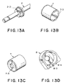
FIG. 13A is an enlarged perspective view of a part of the shaft illustrated in FIG. 4A;
FIG. 13B is an enlarged perspective view of a cap included in the hinge unit, as seen from one side;
FIG. 13C is an enlarged perspective view of the cap as seen from the other side;
FIG. 13D is an enlarged perspective view of a third shell element included in the hinge unit;
FIG. 14A is an enlarged perspective view of a first shell element included in the hinge unit;
FIG. 14B is an enlarged perspective view of a second shell element included in the hinge unit;
FIG. 15A is an enlarged perspective view showing a relaxed state of a flexible part of the FPC when the camera module is in an initial state;
FIG. 15B is an enlarged perspective view showing a stretched state of the flexible part of the FPC when the camera module is in a 180°-rotated state;
FIG. 16A is an enlarged perspective sectional view of the hinge unit when the camera module is in the initial state or in the 180°-rotated state;
FIG. 16B is an enlarged perspective sectional view similar to FIG. 16A except that the shaft is removed;
FIG. 16C is an enlarged perspective sectional view of the hinge unit when the camera module is rotated by about 20° from the initial state or the 180°-rotated state; and
FIG. 16D is an enlarged perspective sectional view similar to FIG. 16C except that the shaft is removed.
DESCRIPTION OF THE PREFERRED EMBODIMENTS
Now, description will be made as regards a hinge unit according to an embodiment of this invention. The hinge unit can be used in a camera-equipped electronic apparatus.
At first referring to FIGS. 1A, 1B, and 2A to 2D, the description will be made as regards a whole of the camera-equipped electronic apparatus in order to facilitate an understanding of this invention. Referring to FIGS. 1A and 1B, a camera module 12 as a first apparatus element is incorporated into an electronic apparatus 19 as a second apparatus element by the use of a hinge unit 14. As shown in FIG. 1A, the hinge unit 14 with the camera module 12 preliminarily attached thereto is clamped by an upper protector 15 and a lower protector 16 from upper and lower sides thereof, respectively. Next, as illustrated in FIG. 1B, the hinge unit 14 is clamped by upper and lower support portions 17-1 and 18-1 of upper and lower main bodies 17 and 18 of the electronic apparatus 19 from the upper and the lower sides thereof, respectively.
In the above-mentioned manner, the camera module 12 is rotatably attached to the electronic apparatus 19 via the hinge unit 14 as illustrated in FIGS. 2A and 2B. In FIGS. 2C and 2D, the camera module 12 is rotated by 180°.
The lower main body 18 has a surface provided with a display portion, such as a LCD, and an operating portion 18-2. By manipulating the operating portion 18-2, a front view and a user himself can be photographed as an object in the state illustrated in FIGS. 2A and 2B and in the state illustrated in FIGS. 2C and 2D, respectively, while confirming the object at the display portion.
Next referring to FIG. 3, various components of the hinge unit 14 will be described.
The hinge unit 14 comprises a flexible board (FPC) 1 as a circuit board, a shaft 2, a first shell element 3, a second shell element 4, a stopper 5, a coil spring 6, a cap 7, a third shell element 8, and a E-shaped snap ring 9. Assembling of the hinge unit 14 will later be described in detail.
To the hinge unit 14, press-connecting-type connectors 10 and 11, the camera module 12, a fitting metal 13, and a board-to-board connector 15 are combined. Thus, the hinge unit 14 with the camera module 12 preliminarily attached thereto is produced.
Referring to FIG. 4A, the shaft 2 has a first rotation stopper 2-1 having a rectangular flange-like shape and formed in the vicinity of one end of the shaft 2. The shaft 2 has a second rotation stopper 2-2 (which will later be described) formed at a distance from the other end of the shaft 2.
Referring to FIG. 4B, the flexible board 1 has a double-sided tape 1-1 preliminarily adhered to its one end. By the double-sided tape 1-1, the flexible board 1 is fixed to the shaft 2 between the first and the second rotation stoppers 2-1 and 2-2. The flexible board 1 further has a bendable portion 1-2 as a flexible portion, a fixed portion 1-3, a connector fitting portion 1-4, and a shield layer 1-5. The bendable portion 1-2 is wound around the shaft 2 in a plurality of turns.
Referring to FIGS. 5 to 12, description will be made of a series of assembling steps of an assembly of the camera module 12 and the hinge unit 14.
At first, the shaft 2 with the FPC 1 wound around and fixed thereto is clamped and fixed by the first and the second shell elements 3 and 4 as depicted by arrows in FIG. 5. A combination of the first and the second shell elements 3 and 4 will be called a first member. The first member is provided with a rotation stopper 3-1. The rotation stopper 3-1 is engaged with the first rotation stopper 2-1 of the shaft 2 so that the first member is unrotatable with respect to the shaft 2. The first rotation stopper 2-1 of the shaft 2 is engaged with the first and the second shell elements 3 and 4 also in an axial direction so that the first member is axially unmovable with respect to the shaft 2.
The stopper 5 is attached to the fixing portion 1-3 of the FPC 1 as depicted by an arrow in FIG. 6. The board-to-board connector 15 is attached to the connector fitting portion 1-4 of the FPC 1. In most cases, the board-to-board connector 15 is preliminarily soldered and connected to the connector fitting portion 1-4 of the FPC 1 prior to the assembling steps.
To the shaft 2, the coil spring 6 as an elastic member, the cylindrical cap 7 as an intermediate member covering the coil spring 6, and the third shell element 8 of a tubular shape are successively attached as depicted by arrows in FIG. 7. Further, the E-shaped snap ring 9 is attached to the shaft 2 as depicted by an arrow in FIG. 8 so as to prevent the third shell element 8 from being released form the shaft 2. Thus, the third shell element 8 is rotatable and axially unmovable with respect to the shaft 2. Therefore, the third shell element 8 is rotatable with respect to the first member comprising the first and the second shell elements 3 and 4. The third shell element 8 may be called a second member.
Referring to FIGS. 7 and 8 in combination, the cap 7 is inserted into the interior of the third shell element 8. The coil spring 6 is disposed inside the cap 7. The cap 7 is provided with an inward flange 7-1 formed at a first axial end thereof. The coil spring 6 is interposed between the inward flange 7-1 and the second rotation stopper 2-2 in a compressed state. In this state, the cap 7 is urged by a restoring force of the coil spring 6 towards an axial end plate 8-1 which is provided at a first axial end of the third shell element 8. The third shell element 8 has a cover portion 8-2 extending in the axial direction so as to cover not only the cap 7 and the coil spring 6 but also the bendable portion 1-2 of the flexible board 1.
As depicted by an arrow in FIG. 9, the press-connecting-type connector 10 is inserted into the first shell element 3. At this time, the press-connecting-type connector 11 of a different type illustrated in FIG. 3 may be used. Thereafter, the camera module 12 is inserted into the first shell element 3 as depicted by an arrow in FIG. 10.
Finally, as depicted by an arrow in FIG. 11, the fixing metal 13 is attached to the first shell element 3. Thus, the hinge unit 14 with the camera module 12 is completed as illustrated in FIG. 12.
Further referring to FIGS. 13A to 13D, 14A, and 14B, description will be made of a detailed structure of the hinge unit 14.
The second rotation stopper 2-2 of the shaft 2 is formed into a non-circular flange-like shape as illustrated in FIG. 13A. The cap 7 is provided with a mating rotation stopper 7-2 formed on an inner surface of an opening which is opened at a second axial end of the cap 7. The mating rotation stopper 7-2 has a non-cylindrical surface substantially equivalent to an outer peripheral surface of the second rotation stopper 2-2 of the shaft 2. The mating rotation stopper 7-2 of the cap 7 is snuggly fitted over the second rotation stopper 2-2 of the shaft 2 so that the cap 7 is unrotatable and axially movable with respect to the shaft 2.
As illustrated in FIG. 13C, the cap 7 is provided with the inward flange 7-1 formed at the first axial end as described above. The inward flange 7-1 has an outer surface provided with a depressed portion 7-3 extending in a radial direction. The depressed portion 7-3 is defined by a pair of side walls inclined so that an opening of the depressed portion 7-3 is wider than a bottom thereof in section.
On the other hand, as illustrated in FIG. 13D, the axial end plate 8-1 of the third shell element 8 is provided with a protruding portion 8-3 formed on its inner surface and extending in the radial direction. The protruding portion 8-3 has a shape adapted to be substantially tightly fitted to the depressed portion 7-3 in the axial direction. When fitted to each other, the protruding portion 8-3 and the depressed portion 7-3 form an engaging structure for engaging the third shell element 8 and the cap 7 with each other in a rotating direction. When a rotating force not smaller than a predetermined value is applied between the third shell element 8 and the cap 7, the engaging structure releases the engagement between the third shell element 8 and the cap 7 with energization of the coil spring 6, as will later be described in detail. In order to provide the rotating force, the third shell element 8 has an outer peripheral surface of a non-circular shape and is prevented from rotation with respect to the electronic apparatus.
The third shell element 8 is provided with a stopper 8-4 at a second axial end thereof as shown in FIG. 13D. As shown in FIGS. 14A and 14B, the first and the second shell elements 3 and 4 are provided with stoppers 3-2 and 4-2 which limit a rotation angle of the third shell element 8 in cooperation with the stopper 8-4, By selecting locations of the stoppers 3-2, 4-2, and 8-4, the rotation angle can be changed. Herein, the rotation angle is set at 180°.
Referring to FIG. 15A, the camera module 12 is in an initial state (i.e., the camera module 12 is received in an inner space, in other words, the camera module 12 is held at a front view photographing position). Referring to FIG. 15B, the camera module 12 is rotated by 180° (i.e., the camera module 12 is protruded, in other words, the camera module 12 is held at a self image photographing position). In FIG. 15A, the bendable portion 1-2 of the FPC 1 is relaxed. In FIG. 15B, the bendable portion 1-2 is stretched.
Referring to FIG. 16A, a rotation brake portion and a click portion are shown in the state where the camera module 12 is in the initial state or the 180°-rotated state. In FIG. 16B, the shaft 2 is removed from the state in FIG. 16A. In FIG. 16C, the rotation brake portion and the click portion are shown in the state where the camera module 12 is rotated by about 20° from the initial state or the 180°-rotated state. In FIG. 16D, the shaft 2 is removed from the state in FIG. 16C.
In the states illustrated in FIGS. 16A and 16B, the protruding portion 8-3 formed inside the third shell element 8 and the depressed portion 7-3 of the cap 7 are fitted to each other. Since the first shell element 3 is fixed to the shaft 2, the shaft 2 is rotated when the camera module 12 is rotated. Since the cap 7 is inhibited from rotation with respect to the shaft 2, the cap 7 is rotated together with the shaft 2. However, the cap 7 is slidable in the axial direction. Therefore, as illustrated in FIGS. 16C and 16D, when the cap 7 starts rotation following the rotation of the shaft 2, the depressed portion 7-3 of the cap 7 is disengaged from the protruding portion 8-3 of the third shell element 8. Further, the cap 7 is moved in the axial direction away from the axial end plate 8-1 of the third shell element 8 to press the coil spring 6 against the second rotation stopper 2-2 of the shaft 2. Therefore, a frictional resistance produced between the coil spring 6 and the second rotation stopper 2-2 serves as a rotation brake so that the camera module 12 is prevented from being rotated due to its weight. In this event, a combination of the coil spring 6 and the second rotation stopper 2-2 will be referred to as the rotation brake portion.
Returning from the state illustrated in FIGS. 16C and 16D to the state illustrated in FIGS. 16A and 16B, the depressed portion 7-3 of the cap 7 is faced to the protruding portion 8-3 of the third shell element 8 and the cap 7 is pushed back by the coil spring 6. As a consequence, the depressed portion 7-3 of the cap 7 is fitted again over the protruding portion 8-3 of the third shell element 8. At this time, appropriate click feeling is obtained. In this event, a combination of the coil spring 6, the depressed portion 7-3, and the protruding portion 8-3 will be referred to as the click portion.
In this state also, the coil spring 6 is not unloaded but compressed. The camera module 12 is kept in the initial state or the 180°-rotated state by a force which is required for the depressed portion 7-3 of the cap 7 to move across the protruding portion 8-3 of the third shell 8.
As will presently be described, the above-mentioned hinge unit 14 may easily be provided with EMC protection. Specifically, a shell forming member, such as the first, the second, and the third shell elements 3, 4, 8, is made of a metal or a resin with a metal film formed on its surface. On the other hand, as shown in FIG. 4B, the FPC 1 is provided with a shield layer 1-5 of conductive material at a portion exposed outward from the shell forming member. The shield layer 1-5 continuously extends to the fixing portion 1-3 and electrically connected to the shell forming member. With this structure, the bendable portion 1-2 of the FPC 1 requires no shield layer. Therefore, the FPC 1 can be reduced in thickness so that an appropriate flexibility or bendability is maintained.
While this invention has thus far been described in connection with the preferred embodiment thereof, it will be readily possible for those skilled in the art to put this invention into practice in various other manners without departing from the scope set forth in the appended claims. In the foregoing, the hinge unit with the camera module has been described. Alternatively, board-to-board connectors may be mounted on opposite ends of the FPC without mounting the camera module. In this case, the other end of the FPC has a similar structure. The hinge unit is applicable not only to the camera-equipped electronic apparatus but also to various other electronic apparatuses such as a mobile telephone, a personal digital assistant (PDA), and a notebook-type personal computer.

Claims (13)

1. A hinge unit for use in an electronic apparatus, said hinge unit comprising:
a shaft which comprises a first part, a first rotation stopper, and a second part that is positioned between the first part and the first rotation stopper in an axial direction of said shaft;
a first member which holds the first part of said shaft, wherein said first member is not rotatable and is not axially movable with respect to said shaft, and said first member cooperates with the first rotation stopper to define a space between said first member and the first rotation stopper of said shaft along the axial direction of said shaft;
a circuit board which comprises a flexible portion which is wound around the second part of said shaft in the space, wherein the flexible portion has an end which is fixed to the second part of said shaft;
a second member which is rotatable in a rotating direction with respect to said shaft, and which is not axially movable with respect to said shaft;
an intermediate member which is faced to said second member in the axial direction, wherein said intermediate member is not rotatable with respect to the first rotation stopper of said shaft and is axially movable with respect to said shaft;
an elastic member which is interposed between said shaft and said intermediate member, and which urges said intermediate member towards said second member in the axial direction; and
an engaging structure which engages said second member and said intermediate member with each other in the rotating direction,
wherein said engaging structure releases the engagement between said second member and said intermediate member, and said elastic member is energized, in response to a rotating force applied between said second member and said intermediate member.
2. The hinge unit according to claim 1, wherein said engaging structure comprises a depressed portion in said intermediate member and a protruding portion formed on said second member to be fitted to said depressed portion in the axial direction.
3. The hinge unit according to claim 1, wherein said first member comprises a first shell element and a second shell element connected to said first shell element, and said shaft is held between said first and said second shell elements.
4. The hinge unit according to claim 3, further comprising a second rotation stopper which engages said shaft and said first and said second shell elements with each other in the rotating direction.
5. The hinge unit according to claim 1, wherein said second member comprises a cover portion which extends in the axial direction to cover said flexible portion.
6. The hinge unit according to claim 1, wherein said intermediate member has a cylindrical shape and is fitted around said shaft to be axially movable with respect to said shaft, and
wherein said first rotation stopper engages said shaft and said intermediate member with each other in the rotating direction.
7. The hinge unit according to claim 6, wherein said first rotation stopper protrudes around said shaft, and said elastic member is interposed between said first rotation stopper and said intermediate member in the axial direction.
8. The hinge unit according to claim 7, wherein said elastic member comprises a compression coil spring.
9. The hinge unit according to claim 8, wherein said intermediate member comprises an inward flange, and said compression coil spring is interposed between said first rotation stopper and said inward flange in a compressed state.
10. The hinge unit according to claim 9, wherein said second member comprises a cover portion which covers said intermediate member, said compression coil spring, and said flexible portion.
11. The hinge unit according to claim 10, wherein said first and said second members have a conductive structure.
12. An electronic apparatus comprising:
the hinge unit according to claim 1;
a first apparatus element connected to said first member; and
a second apparatus element connected to said second member.
13. The electronic apparatus according to claim 12, wherein said first apparatus element comprises a camera module.
US10/944,599 2003-09-19 2004-09-17 Simple hinge unit capable of providing electrical connection in an electronic apparatus Expired - Fee Related US7477736B2 (en)

Applications Claiming Priority (2)

Application Number Priority Date Filing Date Title
JP2003328298A JP3982760B2 (en) 2003-09-19 2003-09-19 Hinge device for electronic equipment
JP328298/2003 2003-09-19

Publications (2)

Publication Number Publication Date
US20050060842A1 US20050060842A1 (en) 2005-03-24
US7477736B2 true US7477736B2 (en) 2009-01-13

Family

ID=34191392

Family Applications (1)

Application Number Title Priority Date Filing Date
US10/944,599 Expired - Fee Related US7477736B2 (en) 2003-09-19 2004-09-17 Simple hinge unit capable of providing electrical connection in an electronic apparatus

Country Status (6)

Country Link
US (1) US7477736B2 (en)
EP (1) EP1517521A1 (en)
JP (1) JP3982760B2 (en)
KR (1) KR100662317B1 (en)
CN (1) CN1599380A (en)
TW (1) TWI259048B (en)

Cited By (3)

* Cited by examiner, † Cited by third party
Publication number Priority date Publication date Assignee Title
US20040218092A1 (en) * 2003-04-30 2004-11-04 Lg Electronics Inc. Camera assembly for a mobile communication device
US20060268142A1 (en) * 2005-05-30 2006-11-30 Samsung Electronics Co., Ltd. Portable terminal having camera lens assembly
US20110045877A1 (en) * 2009-08-19 2011-02-24 Samsung Electronics Co., Ltd. Pop-up apparatus for portable communication device

Families Citing this family (11)

* Cited by examiner, † Cited by third party
Publication number Priority date Publication date Assignee Title
TW200509480A (en) * 2003-08-27 2005-03-01 Mitsumi Electric Co Ltd Connector for camera module
CN100399637C (en) * 2005-05-16 2008-07-02 富士康(昆山)电脑接插件有限公司 Electric connector
TWM304793U (en) * 2006-04-03 2007-01-11 Hon Hai Prec Ind Co Ltd Electrical connector assembly
CN200941518Y (en) * 2006-08-01 2007-08-29 富士康(昆山)电脑接插件有限公司 Electrical connector
US7617571B2 (en) * 2006-10-30 2009-11-17 Illinois Tool Works Inc. Pin-less assist grip handle assembly
JP4874174B2 (en) * 2007-06-25 2012-02-15 富士通東芝モバイルコミュニケーションズ株式会社 Electronics
CN101598174B (en) * 2008-06-05 2011-06-29 英业达股份有限公司 Connection structure between display panel and host machine
TWI513914B (en) * 2012-08-14 2015-12-21 Au Optronics Corp Electronic device and display module used therein with hinge signal passage design
JP6415193B2 (en) 2014-09-05 2018-10-31 キヤノン株式会社 Electronics
CN109769366B (en) * 2017-11-09 2021-05-04 华为技术有限公司 Interconnection mechanism, cabinet and electronic equipment
CN109981827B (en) * 2017-12-28 2021-02-26 Oppo广东移动通信有限公司 Terminal equipment and camera assembly thereof

Citations (14)

* Cited by examiner, † Cited by third party
Publication number Priority date Publication date Assignee Title
JPH09148030A (en) 1995-11-24 1997-06-06 Matsushita Electric Ind Co Ltd Rotative connecting device
JPH10290084A (en) 1997-04-15 1998-10-27 Sony Corp Electronic equipment
JPH11168289A (en) 1997-12-04 1999-06-22 Japan Aviation Electron Ind Ltd Fpc fixing structure in hinge part of two opening/closing housings
JP2000216567A (en) 1999-01-25 2000-08-04 Seiko Instruments Inc Holding structure for flexible board and electronic apparatus employing it
US6115886A (en) * 1997-06-16 2000-09-12 Katoh Electrical Machinery Co., Ltd. Hinge apparatus
JP3145652B2 (en) 1997-05-07 2001-03-12 株式会社ストロベリーコーポレーション Hinge device
JP3220412B2 (en) 1997-05-12 2001-10-22 株式会社ニフコ Hinge mechanism and hinge unit
JP2002232535A (en) 2001-01-31 2002-08-16 Sanyo Electric Co Ltd Telephone system
JP2002333012A (en) 2002-02-25 2002-11-22 Kato Electrical Mach Co Ltd Hinge device
JP2003100410A (en) 2001-09-25 2003-04-04 Japan Aviation Electronics Industry Ltd Hinge connector, and electronic equipment
JP2003120654A (en) 2001-10-11 2003-04-23 Nec Saitama Ltd Collapsible portable communication apparatus
US6754507B2 (en) * 2000-04-19 2004-06-22 Fujitsu Limited Folding-type mobile terminal having a metal hinge, metal chassis and synthetic-resin cases
US6879337B2 (en) * 2001-05-31 2005-04-12 Matsushita Electric Industrial Co., Ltd. Portable terminal device with camera
US7245948B2 (en) * 2003-04-01 2007-07-17 Samsung Electro-Mechanics Co., Ltd. Cellular phone and automatic revolution method thereof

Family Cites Families (6)

* Cited by examiner, † Cited by third party
Publication number Priority date Publication date Assignee Title
TW519785B (en) * 2000-12-20 2003-02-01 Japan Aviation Electron Folding-type electronic apparatus comprising two base members hinge-connected by a hinge connector with an FPC
JP2002279856A (en) 2001-03-15 2002-09-27 Alps Electric Co Ltd Opening and closing detection device
KR100442598B1 (en) * 2001-09-06 2004-08-02 삼성전자주식회사 Rotational lens housing mounting device and folder-type telephone therewith
KR100431558B1 (en) * 2001-12-12 2004-05-22 (주)이엘에스 The apparatus of opening and shutting for cellular phone
KR100492554B1 (en) * 2002-11-29 2005-06-02 엘지전자 주식회사 Hinge apparatus for mobile phone
KR100511309B1 (en) * 2003-05-12 2005-08-31 엘지전자 주식회사 Plexible pcb arrangement structure for mobile phone

Patent Citations (14)

* Cited by examiner, † Cited by third party
Publication number Priority date Publication date Assignee Title
JPH09148030A (en) 1995-11-24 1997-06-06 Matsushita Electric Ind Co Ltd Rotative connecting device
JPH10290084A (en) 1997-04-15 1998-10-27 Sony Corp Electronic equipment
JP3145652B2 (en) 1997-05-07 2001-03-12 株式会社ストロベリーコーポレーション Hinge device
JP3220412B2 (en) 1997-05-12 2001-10-22 株式会社ニフコ Hinge mechanism and hinge unit
US6115886A (en) * 1997-06-16 2000-09-12 Katoh Electrical Machinery Co., Ltd. Hinge apparatus
JPH11168289A (en) 1997-12-04 1999-06-22 Japan Aviation Electron Ind Ltd Fpc fixing structure in hinge part of two opening/closing housings
JP2000216567A (en) 1999-01-25 2000-08-04 Seiko Instruments Inc Holding structure for flexible board and electronic apparatus employing it
US6754507B2 (en) * 2000-04-19 2004-06-22 Fujitsu Limited Folding-type mobile terminal having a metal hinge, metal chassis and synthetic-resin cases
JP2002232535A (en) 2001-01-31 2002-08-16 Sanyo Electric Co Ltd Telephone system
US6879337B2 (en) * 2001-05-31 2005-04-12 Matsushita Electric Industrial Co., Ltd. Portable terminal device with camera
JP2003100410A (en) 2001-09-25 2003-04-04 Japan Aviation Electronics Industry Ltd Hinge connector, and electronic equipment
JP2003120654A (en) 2001-10-11 2003-04-23 Nec Saitama Ltd Collapsible portable communication apparatus
JP2002333012A (en) 2002-02-25 2002-11-22 Kato Electrical Mach Co Ltd Hinge device
US7245948B2 (en) * 2003-04-01 2007-07-17 Samsung Electro-Mechanics Co., Ltd. Cellular phone and automatic revolution method thereof

Cited By (6)

* Cited by examiner, † Cited by third party
Publication number Priority date Publication date Assignee Title
US20040218092A1 (en) * 2003-04-30 2004-11-04 Lg Electronics Inc. Camera assembly for a mobile communication device
US7847860B2 (en) * 2003-04-30 2010-12-07 Lg Electronics, Inc. Camera assembly for a mobile communication device
US20060268142A1 (en) * 2005-05-30 2006-11-30 Samsung Electronics Co., Ltd. Portable terminal having camera lens assembly
US7859585B2 (en) * 2005-05-30 2010-12-28 Samsung Electronics Co., Ltd Portable terminal having camera lens assembly
US20110045877A1 (en) * 2009-08-19 2011-02-24 Samsung Electronics Co., Ltd. Pop-up apparatus for portable communication device
US8634882B2 (en) * 2009-08-19 2014-01-21 Samsung Electronics Co., Ltd. Pop-up apparatus for portable communication device

Also Published As

Publication number Publication date
TWI259048B (en) 2006-07-21
JP3982760B2 (en) 2007-09-26
KR20050028882A (en) 2005-03-23
KR100662317B1 (en) 2006-12-28
CN1599380A (en) 2005-03-23
EP1517521A1 (en) 2005-03-23
JP2005090707A (en) 2005-04-07
TW200524511A (en) 2005-07-16
US20050060842A1 (en) 2005-03-24

Similar Documents

Publication Publication Date Title
US7477736B2 (en) Simple hinge unit capable of providing electrical connection in an electronic apparatus
KR100584397B1 (en) Camera lens assembly for portable terminal
US7392071B2 (en) Rotary module with digital camera module
US7392072B2 (en) Camera lens module and portable wireless terminal having the same
US7672118B2 (en) Electronic apparatus
WO2002076067A1 (en) Mobile terminal device having camera function
US20060078326A1 (en) Image-taking apparatus
US7191491B2 (en) Hinge connector having a shaft member of a simple structure and electronic apparatus including the hinge connector
JP5489699B2 (en) Electronics
US7264171B2 (en) Electronic device with embedded image capture module
US10951795B2 (en) Image pickup apparatus having movable part that is movable between retracted position and projecting position
US6975273B1 (en) Antenna with camera lens assembly for portable radiotelephone
JP6265762B2 (en) Electronics
JP2003262913A (en) Portable terminal unit with camera
JP5455224B2 (en) Electronics
CN110892703A (en) Image capturing apparatus
US9462714B2 (en) Hinge unit capable of preventing rotation from exceeding fully-open position and electronic apparatus equipped with hinge unit
JP2003037375A (en) Foldable electronic equipment
JP2012038465A (en) Electronic apparatus
JP2018056607A (en) Electronic apparatus
JP6265763B2 (en) Electronics
KR20060023623A (en) Method for improving lcd module esd in portable wireless terminal
JP2014052448A (en) Imaging device
JP2009025660A (en) Electronic device
CN117499765A (en) Camera assembly and electronic equipment

Legal Events

Date Code Title Description
AS Assignment

Owner name: JAPAN AVIATION ELECTRONICS INDUSTRY, LIMITED, JAPA

Free format text: ASSIGNMENT OF ASSIGNORS INTEREST;ASSIGNORS:IBARAKI, KAZUAKI;HIGUCHI, MASAO;HARADA, HARUYUKI;REEL/FRAME:015811/0760

Effective date: 20040914

FEPP Fee payment procedure

Free format text: PAYOR NUMBER ASSIGNED (ORIGINAL EVENT CODE: ASPN); ENTITY STATUS OF PATENT OWNER: LARGE ENTITY

FPAY Fee payment

Year of fee payment: 4

REMI Maintenance fee reminder mailed
LAPS Lapse for failure to pay maintenance fees
STCH Information on status: patent discontinuation

Free format text: PATENT EXPIRED DUE TO NONPAYMENT OF MAINTENANCE FEES UNDER 37 CFR 1.362

FP Lapsed due to failure to pay maintenance fee

Effective date: 20170113