US7475672B2 - Inductive ignition control system - Google Patents
Inductive ignition control system Download PDFInfo
- Publication number
- US7475672B2 US7475672B2 US11/384,197 US38419706A US7475672B2 US 7475672 B2 US7475672 B2 US 7475672B2 US 38419706 A US38419706 A US 38419706A US 7475672 B2 US7475672 B2 US 7475672B2
- Authority
- US
- United States
- Prior art keywords
- engine
- ignition
- set forth
- controller
- rotatable body
- Prior art date
- Legal status (The legal status is an assumption and is not a legal conclusion. Google has not performed a legal analysis and makes no representation as to the accuracy of the status listed.)
- Expired - Fee Related, expires
Links
Images


Classifications
-
- F—MECHANICAL ENGINEERING; LIGHTING; HEATING; WEAPONS; BLASTING
- F02—COMBUSTION ENGINES; HOT-GAS OR COMBUSTION-PRODUCT ENGINE PLANTS
- F02P—IGNITION, OTHER THAN COMPRESSION IGNITION, FOR INTERNAL-COMBUSTION ENGINES; TESTING OF IGNITION TIMING IN COMPRESSION-IGNITION ENGINES
- F02P3/00—Other installations
- F02P3/02—Other installations having inductive energy storage, e.g. arrangements of induction coils
- F02P3/04—Layout of circuits
- F02P3/045—Layout of circuits for control of the dwell or anti dwell time
- F02P3/0453—Opening or closing the primary coil circuit with semiconductor devices
- F02P3/0456—Opening or closing the primary coil circuit with semiconductor devices using digital techniques
-
- F—MECHANICAL ENGINEERING; LIGHTING; HEATING; WEAPONS; BLASTING
- F02—COMBUSTION ENGINES; HOT-GAS OR COMBUSTION-PRODUCT ENGINE PLANTS
- F02P—IGNITION, OTHER THAN COMPRESSION IGNITION, FOR INTERNAL-COMBUSTION ENGINES; TESTING OF IGNITION TIMING IN COMPRESSION-IGNITION ENGINES
- F02P5/00—Advancing or retarding ignition; Control therefor
- F02P5/04—Advancing or retarding ignition; Control therefor automatically, as a function of the working conditions of the engine or vehicle or of the atmospheric conditions
- F02P5/145—Advancing or retarding ignition; Control therefor automatically, as a function of the working conditions of the engine or vehicle or of the atmospheric conditions using electrical means
- F02P5/15—Digital data processing
- F02P5/1502—Digital data processing using one central computing unit
-
- F—MECHANICAL ENGINEERING; LIGHTING; HEATING; WEAPONS; BLASTING
- F02—COMBUSTION ENGINES; HOT-GAS OR COMBUSTION-PRODUCT ENGINE PLANTS
- F02P—IGNITION, OTHER THAN COMPRESSION IGNITION, FOR INTERNAL-COMBUSTION ENGINES; TESTING OF IGNITION TIMING IN COMPRESSION-IGNITION ENGINES
- F02P7/00—Arrangements of distributors, circuit-makers or -breakers, e.g. of distributor and circuit-breaker combinations or pick-up devices
- F02P7/06—Arrangements of distributors, circuit-makers or -breakers, e.g. of distributor and circuit-breaker combinations or pick-up devices of circuit-makers or -breakers, or pick-up devices adapted to sense particular points of the timing cycle
- F02P7/067—Electromagnetic pick-up devices, e.g. providing induced current in a coil
-
- F—MECHANICAL ENGINEERING; LIGHTING; HEATING; WEAPONS; BLASTING
- F02—COMBUSTION ENGINES; HOT-GAS OR COMBUSTION-PRODUCT ENGINE PLANTS
- F02P—IGNITION, OTHER THAN COMPRESSION IGNITION, FOR INTERNAL-COMBUSTION ENGINES; TESTING OF IGNITION TIMING IN COMPRESSION-IGNITION ENGINES
- F02P7/00—Arrangements of distributors, circuit-makers or -breakers, e.g. of distributor and circuit-breaker combinations or pick-up devices
- F02P7/06—Arrangements of distributors, circuit-makers or -breakers, e.g. of distributor and circuit-breaker combinations or pick-up devices of circuit-makers or -breakers, or pick-up devices adapted to sense particular points of the timing cycle
- F02P7/077—Circuits therefor, e.g. pulse generators
-
- F—MECHANICAL ENGINEERING; LIGHTING; HEATING; WEAPONS; BLASTING
- F02—COMBUSTION ENGINES; HOT-GAS OR COMBUSTION-PRODUCT ENGINE PLANTS
- F02D—CONTROLLING COMBUSTION ENGINES
- F02D41/00—Electrical control of supply of combustible mixture or its constituents
- F02D41/009—Electrical control of supply of combustible mixture or its constituents using means for generating position or synchronisation signals
- F02D2041/0092—Synchronisation of the cylinders at engine start
-
- F—MECHANICAL ENGINEERING; LIGHTING; HEATING; WEAPONS; BLASTING
- F02—COMBUSTION ENGINES; HOT-GAS OR COMBUSTION-PRODUCT ENGINE PLANTS
- F02D—CONTROLLING COMBUSTION ENGINES
- F02D2200/00—Input parameters for engine control
- F02D2200/02—Input parameters for engine control the parameters being related to the engine
- F02D2200/04—Engine intake system parameters
- F02D2200/0404—Throttle position
-
- F—MECHANICAL ENGINEERING; LIGHTING; HEATING; WEAPONS; BLASTING
- F02—COMBUSTION ENGINES; HOT-GAS OR COMBUSTION-PRODUCT ENGINE PLANTS
- F02D—CONTROLLING COMBUSTION ENGINES
- F02D2200/00—Input parameters for engine control
- F02D2200/50—Input parameters for engine control said parameters being related to the vehicle or its components
- F02D2200/503—Battery correction, i.e. corrections as a function of the state of the battery, its output or its type
-
- F—MECHANICAL ENGINEERING; LIGHTING; HEATING; WEAPONS; BLASTING
- F02—COMBUSTION ENGINES; HOT-GAS OR COMBUSTION-PRODUCT ENGINE PLANTS
- F02D—CONTROLLING COMBUSTION ENGINES
- F02D41/00—Electrical control of supply of combustible mixture or its constituents
- F02D41/009—Electrical control of supply of combustible mixture or its constituents using means for generating position or synchronisation signals
-
- F—MECHANICAL ENGINEERING; LIGHTING; HEATING; WEAPONS; BLASTING
- F02—COMBUSTION ENGINES; HOT-GAS OR COMBUSTION-PRODUCT ENGINE PLANTS
- F02P—IGNITION, OTHER THAN COMPRESSION IGNITION, FOR INTERNAL-COMBUSTION ENGINES; TESTING OF IGNITION TIMING IN COMPRESSION-IGNITION ENGINES
- F02P5/00—Advancing or retarding ignition; Control therefor
- F02P5/04—Advancing or retarding ignition; Control therefor automatically, as a function of the working conditions of the engine or vehicle or of the atmospheric conditions
- F02P5/145—Advancing or retarding ignition; Control therefor automatically, as a function of the working conditions of the engine or vehicle or of the atmospheric conditions using electrical means
- F02P5/15—Digital data processing
- F02P5/1502—Digital data processing using one central computing unit
- F02P5/1514—Digital data processing using one central computing unit with means for optimising the use of registers or of memories, e.g. interpolation
-
- F—MECHANICAL ENGINEERING; LIGHTING; HEATING; WEAPONS; BLASTING
- F02—COMBUSTION ENGINES; HOT-GAS OR COMBUSTION-PRODUCT ENGINE PLANTS
- F02P—IGNITION, OTHER THAN COMPRESSION IGNITION, FOR INTERNAL-COMBUSTION ENGINES; TESTING OF IGNITION TIMING IN COMPRESSION-IGNITION ENGINES
- F02P5/00—Advancing or retarding ignition; Control therefor
- F02P5/04—Advancing or retarding ignition; Control therefor automatically, as a function of the working conditions of the engine or vehicle or of the atmospheric conditions
- F02P5/145—Advancing or retarding ignition; Control therefor automatically, as a function of the working conditions of the engine or vehicle or of the atmospheric conditions using electrical means
- F02P5/155—Analogue data processing
-
- Y—GENERAL TAGGING OF NEW TECHNOLOGICAL DEVELOPMENTS; GENERAL TAGGING OF CROSS-SECTIONAL TECHNOLOGIES SPANNING OVER SEVERAL SECTIONS OF THE IPC; TECHNICAL SUBJECTS COVERED BY FORMER USPC CROSS-REFERENCE ART COLLECTIONS [XRACs] AND DIGESTS
- Y02—TECHNOLOGIES OR APPLICATIONS FOR MITIGATION OR ADAPTATION AGAINST CLIMATE CHANGE
- Y02T—CLIMATE CHANGE MITIGATION TECHNOLOGIES RELATED TO TRANSPORTATION
- Y02T10/00—Road transport of goods or passengers
- Y02T10/10—Internal combustion engine [ICE] based vehicles
- Y02T10/40—Engine management systems
Definitions
- the present invention relates to ignition systems for internal combustion engines. More specifically, the invention relates to an ignition system of the inductive type having certain novel features.
- Inductive ignition systems are well-known in the art. Conventionally, such systems use a primary coil and a secondary or ignition coil. The primary coil is connected such that a current can flow through it. At a predetermined point in the piston's stroke, a transistor in series with the primary coil circuit opens. As a result, the current through the primary coil quickly goes to zero.
- This rapid change in current through the primary coil induces a voltage across the secondary coil sufficient to arc across a spark plug gap on a spark plug attached to the secondary coil circuit.
- the number of windings in the primary and secondary coils is such that the voltage induced in the secondary coil is high enough to arc across the spark plug gap.
- the present invention recognizes the foregoing and other disadvantages of prior art systems and methods.
- the present invention provides an apparatus for producing an ignition spark in an internal combustion engine.
- the apparatus comprises an inductive ignition device having a primary coil and a secondary coil, flow of current through the primary coil being controlled by an electronic switching element (e.g., a transistor) responsive to a triggering signal.
- a rotatable body e.g., the engine flywheel
- a sensor device is located adjacent to the rotatable body at a fixed position and is operative to produce an output in response to the detectable features.
- the apparatus also includes a controller operative to receive an output from the sensor device and responsively produce the triggering signal so as to have a selected dwell time and ignition position.
- the detectable features comprise a plurality of projections located on the periphery of the rotatable body.
- the projections are preferably located at a plurality of index positions evenly spaced such that one of the index positions is without a corresponding projection.
- the projections may be teeth situated on the periphery of the rotatable body.
- the controller may be further operative to ascertain engine speed and mechanical position by sensing the detectable features and then determine the dwell time and ignition position based thereon.
- the controller may chronologically locate the ignition position by predicting engine position between two of the detectable features.
- the dwell time is determined at least in part based on average engine speed.
- the controller may also sample battery voltage as a factor in determination of the dwell time. If the internal combustion engine is a four stroke engine, the controller may be operative not to produce a triggering signal during the power/exhaust stroke thereof.
- a method for determining time at which an ignition spark will be produced in an internal combustion engine involves providing a rotatable body that turns in synchronism with operation of the engine, the rotatable body having detectable features on a periphery thereof. According to a further step, the detectable features on the rotatable body are sensed so as to ascertain a mechanical position of the engine. A triggering signal is produced so as to yield the ignition spark at a selected ignition position. For example, the ignition spark may be produced on a trailing edge of the triggering signal. In addition, a dwell time of the triggering signal may be varied.
- an apparatus for producing an ignition spark in an internal combustion engine comprises an inductive ignition device having a primary coil and a secondary coil, flow of current through the primary coil being controlled by an electronic switching element responsive to a triggering signal.
- a sensor device is operative to produce an output indicative of engine speed and mechanical position.
- the apparatus further includes a controller operative to receive an output from the sensor device. The controller produces the triggering signal so as to have variable dwell time and ignition position based on the engine speed and mechanical position.
- FIG. 1 is a block diagram of an inductive ignition system constructed in accordance with the present invention
- FIG. 2 is a block diagram of a controller for use with the ignition system of FIG. 1 ;
- FIG. 3 diagrammatically shows a sensor adjacent to the engine flywheel so as to detect the mechanical position thereof
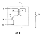
- FIG. 4 is a schematic representation of a typical ignition coil circuit that may be used with the present invention.
- FIG. 5 illustrates a firing signal that may be generated in accordance with the present invention.
- FIGS. 6 through 15 are flowcharts describing various processes executed by a microprocessor for use with an ignition system of the present invention.
- an ignition system of the present invention may be used on a single cylinder engine such as are often utilized for small motorcycles. It should be appreciated, however, that principles of the present invention could be used with other types of internal combustion engines.
- FIG. 1 illustrates a schematic diagram of an ignition system 10 in accordance with the present invention.
- Ignition system 10 includes controller 12 , ignition coil 14 , and spark plug 16 .
- a 12VDC power source 18 is connected to both controller 12 and ignition coil 14 by wires 20 and 22 , respectively.
- Ignition system 10 includes a conventional ignition switch 24 .
- a second switch 26 optionally is provided in the illustrated embodiment.
- switch 26 could be a side stand switch or seat pressure switch in a motorcycle application of the present invention.
- a temperature sensor 28 is provided for sensing the temperature of the engine block.
- the temperature sensor is a thermistor that outputs a linearly changing voltage as temperature changes.
- the temperature of the engine block is used as an input to the control logic of the system; different timing curves may be used for warm-up and steady state operation of the engine.
- transducer 30 (which is a variable reluctance transducer in this embodiment) is positioned adjacent the outer diameter of engine flywheel 29 .
- Flywheel 29 has a series of teeth positions (e.g., twenty-four) (such as those indicated at 31 ) around its circumference.
- One of the positions (indicated at G) is missing a tooth, while the remaining positions have a metal tooth.
- Transducer 30 detects the presence or absence of the teeth as the flywheel turns. This position information is sent from transducer 30 to controller 12 .
- the teeth are positioned around the flywheel, but one skilled in the art will appreciate they could also be on the crankshaft or another location that provides a mechanical indication of engine position.
- a throttle position sensor 32 also communicates with controller 12 .
- the throttle position sensor could be a linear variable displacement transducer, a potentiometer (as in the preferred embodiment), or any other suitable sensor.
- the throttle position determines the load request from the operator.
- the timing curve utilized by controller 12 may be changed depending on the load request.
- Ground lugs 34 and 36 are provided to connect the controller and ignition coil to vehicle ground.
- An ignition coil input wire 38 runs from controller 12 to ignition coil 14 .
- wire 38 carries a signal to an insulated gate bipolar transistor (IGBT) 35 within the ignition coil 14 and acts as a trigger input to that transistor.
- IGBT insulated gate bipolar transistor
- the operation of the primary and secondary coils (indicated at 37 and 39 , respectively) within the ignition coil 14 is essentially the same as for traditional inductive ignition systems and should be understood by those of skill in the art.
- controller 12 includes ground fault and transient protector 40 , voltage regulator 42 , input signal conditioner 44 , and main processor 46 .
- a signal from transducer 30 is provided to signal conditioner 44 at line 48 .
- signal conditioner 44 conditions the signal from a variable sine curve into a block-shaped wave form for input into main processor 46 .
- Ground fault and transient protector 40 and voltage regulator 42 protect the controller's electronics from voltage spikes in the system.
- Regulator 42 further provides a stable 5-volt signal to main processor 46 and signal conditioner 44 .
- resistors 50 and 52 are configured and valued such that the voltage entering main processor 46 through wire 54 is one-third of the voltage at line 20 . In this manner, processor 46 samples the battery voltage as one factor used in the timing calculations.
- Other inputs to the main processor include throttle position sensor 32 , temperature sensor 28 , and switch 26 .
- the controller uses a processor to provide a signal to ignition coil 14 to fire spark plug 16 .
- this signal (indicated at 55 ) consists of a single digital pulse with prescribed starting and ending positions (relative to the engine crank position) and a duration (referred to as dwell time).
- the signal timing and position is determined by a number of factors, including engine speed, throttle position, engine temperature, and battery voltage.
- the instantaneous engine speed of a single-cylinder four cycle motorcycle engine varies considerably within a firing cycle (due to the use of a light flywheel), perhaps up to a 1000-RPM variation. This variation in engine speed makes it very difficult to predict the position of an appropriate ignition pulse.
- a series of gear teeth 31 are used around flywheel 29 to help closer specify the engine position for controller 12 ( FIG. 3 ).
- Controller 12 through the transducer 30 , detects gear teeth 31 , which in a preferred embodiment are spaced 15 degrees apart on the flywheel's periphery. (although the preferred embodiment uses 15 degrees, that can be modified, based on accuracy requirements by adding more or less gear teeth) For a 15 degree spacing, there should be 24 teeth around the wheel, but there is one tooth missing (as indicated at G in FIG. 3 ) for position synchronization. Typically, the first tooth after the missing tooth gap may be located at 120 degrees Before Top Dead Center (BTDC) in the flywheel's rotation.
- BTDC Top Dead Center
- Each gear tooth 31 is sensed as it passes by transducer 30 , which ultimately produces a digital signal that is input to processor 46 .
- the appropriate edge (either rising or falling) of the digital pulse is used as a timing and position reference for engine speed and rotation, based on the polarity of the sensor.
- processor 46 uses both engine position and the time between pulses to correctly position the spark pulse.
- the controller accomplishes this by counting a prescribed number of tooth pulses (i.e. engine position) to get close to a firing position. Then, the controller switches to a time-based routine that interpolates the correct amount of time delay until firing.
- the background routines are a set of subroutines which are executed once per engine revolution. They are run after the Top Dead Center engine position is detected, since the spark plug has been fired before this occurs. This is also in a region before the next ignition pulse will be generated.
- These subroutines read the throttle position, battery voltage, and engine temperature, computing the present engine speed in RPM, based on the most current period measurement (the time for one engine revolution). The average engine speed is also calculated, based on the current and the previous revolution's engine speed, since there can be variations between the intake/compression and the power/exhaust strokes of the engine cycles.
- the desired dwell time is selected from an internal table, based on battery voltage and average engine speed.
- the desired ignition advance is selected from an internal table, based on throttle position, engine temperature, and average engine speed. Ignition advance is the time between top dead center and the desired firing point. These values are used to compute the correct timing for the next engine cycle.
- an adaptive dwell routine is run to maintain the desired dwell time, and the power and intake/compression cycles of the engine are detected. Separate advance values are maintained for each type of engine cycle because of the wide variation in engine speed between the power and intake/compression strokes.
- the tooth interrupt routine is invoked whenever a pulse is presented at the External Input pin of processor 46 .
- this pin is driven to a logic high, the program that is running at that time is suspended, and the tooth interrupt routine is started.
- this routine is finished, the interrupted program resumes from where it was stopped.
- the interrupt routine records a time stamp (EDGETIME) at each tooth pulse event. It uses this information to compute the time for the most recent pulsewidth, the previous pulsewidth, and the time difference between these two pulsewidths. It also detects synchronization at startup and continues to check this on each revolution of the engine. If the controller loses synchronization for any reason, it resets and starts over.
- EDGETIME time stamp
- the routine also maintains a counter which is used to track engine position at each tooth. Since each tooth represents 15 degrees of engine rotation, each count in the counter equals 15 degrees. Spark and dwell advance values are stored as 2-bytes, one representing an integer value in 15-degree “tooth” counts and the other representing a fractional value of a tooth. These integer and fractional values of dwell and spark advance are computed based on the desired advance relative to the actual tooth position on the flywheel. At each interrupt, a tooth counter is incremented and compared to the integer values of each type of advance. When the counter and the integer values are equal, a subroutine is run to either create the leading or trailing edge of the ignition pulse.
- This subroutine uses the present EDGETIME as a reference time. It also uses the present pulsewidth time and the difference between that pulsewidth and the previous pulsewidth to predict a time in the future at which to create an edge. During the background loop, this computed time is compared to an internal real-time clock. When the times are equal, the appropriate edge is output to create the ignition pulse.
- the dwell time is based on engine speed and battery voltage and defines the actual width of the ignition pulse. As the leading and trailing edges of the ignition pulse are generated, the actual dwell time is computed and is compared to the desired dwell time. If the actual and desired dwell times differ by greater than a small dead-band value, the dwell advance is adjusted by a small amount in the appropriate direction to bring the two dwell times to a value within the dead-band.
- a complete engine sequence consists of two engine revolutions. The first one consists of the intake and compression strokes; the second consists of the power and exhaust strokes.
- the engine will tend to slow down incrementally during the compression stroke, then speed up as the spark is generated and ignites the fuel/air mixture during the power stroke.
- the processor is continually monitoring engine speed at each revolution, it can decide whether the engine is running in the compression or the power cycles and adjust the dwell and spark advance values accordingly. This is done because there can be a wide variation in the engine speed and hence instantaneous engine position between the two cycles. Differentiating between the compression and power cycles and adjusting spark and dwell advances independently increases the accuracy.
- spark plug only needs to be fired during the intake/compression stroke, it is possible to eliminate the firing of the plug on the power/exhaust stroke (commonly called “waste spark”) by detecting these engine cycles. Also, speed differences between adjacent engine cycles can be used to determine an engine “loading” value. This value can be used to adjust spark advance in relation to throttle position, engine speed, and other factors.
- the present invention provides a novel timing control system for an inductive ignition. While one or more preferred embodiments of the invention have been described above, it should be understood that any and all equivalent realizations of the present invention are included within the scope and spirit thereof.
- the embodiments depicted are presented by way of example and are not intended as limitations upon the present invention. Thus, those of ordinary skill in this art should understand that the present invention is not limited to these embodiments since modifications can be made. Therefore, it is contemplated that any and all such embodiments are included in the present invention as may fall within the scope and spirit of the following appended claims.
Landscapes
- Engineering & Computer Science (AREA)
- Chemical & Material Sciences (AREA)
- Combustion & Propulsion (AREA)
- Mechanical Engineering (AREA)
- General Engineering & Computer Science (AREA)
- Theoretical Computer Science (AREA)
- Signal Processing (AREA)
- Physics & Mathematics (AREA)
- Electromagnetism (AREA)
- Ignition Installations For Internal Combustion Engines (AREA)
Abstract
An apparatus for producing an ignition spark in an internal combustion engine. The apparatus comprises an inductive ignition device having a primary coil and a secondary coil, flow of current through the primary coil being controlled by an electronic switching element (e.g., a transistor) responsive to a triggering signal. A rotatable body (e.g., the engine flywheel) having detectable features on a periphery thereof is also provided. A sensor device is located adjacent to the rotatable body at a fixed position and is operative to produce an output in response to the detectable features. The apparatus also includes a controller operative to receive an output from the sensor device and responsively produce the triggering signal so as to have a selected dwell time and ignition position.
Description
This application is based upon and claims the benefit of provisional application Ser. No. 60/663,004, filed Mar. 18, 2005, which is relied upon and incorporated herein by reference.
The present invention relates to ignition systems for internal combustion engines. More specifically, the invention relates to an ignition system of the inductive type having certain novel features.
Inductive ignition systems are well-known in the art. Conventionally, such systems use a primary coil and a secondary or ignition coil. The primary coil is connected such that a current can flow through it. At a predetermined point in the piston's stroke, a transistor in series with the primary coil circuit opens. As a result, the current through the primary coil quickly goes to zero.
This rapid change in current through the primary coil induces a voltage across the secondary coil sufficient to arc across a spark plug gap on a spark plug attached to the secondary coil circuit. The number of windings in the primary and secondary coils is such that the voltage induced in the secondary coil is high enough to arc across the spark plug gap.
An example of a conventional inductive ignition system is disclosed in U.S. Pat. No. 4,487,191, the disclosure of which is incorporated herein by reference.
While conventional inductive ignition systems have been successful at firing a spark plug at approximately the same time during successive rotations of a piston-cylinder engine, there is a need for more precise control over the exact time of firing and the duration/intensity of the spark. Such a new ignition system would have the further benefit of reducing emissions and reducing wear on the engine due to combustion at a non-ideal time in the engine cycle.
The present invention recognizes the foregoing and other disadvantages of prior art systems and methods.
In accordance with one aspect, the present invention provides an apparatus for producing an ignition spark in an internal combustion engine. The apparatus comprises an inductive ignition device having a primary coil and a secondary coil, flow of current through the primary coil being controlled by an electronic switching element (e.g., a transistor) responsive to a triggering signal. A rotatable body (e.g., the engine flywheel) having detectable features on a periphery thereof is also provided. A sensor device is located adjacent to the rotatable body at a fixed position and is operative to produce an output in response to the detectable features. The apparatus also includes a controller operative to receive an output from the sensor device and responsively produce the triggering signal so as to have a selected dwell time and ignition position.
In some exemplary embodiments, the detectable features comprise a plurality of projections located on the periphery of the rotatable body. In this regard, the projections are preferably located at a plurality of index positions evenly spaced such that one of the index positions is without a corresponding projection. For example, the projections may be teeth situated on the periphery of the rotatable body.
It will often be desirable for the controller to synchronize against the detectable features in order to chronologically locate the ignition position. Preferably, the controller may be further operative to ascertain engine speed and mechanical position by sensing the detectable features and then determine the dwell time and ignition position based thereon. The controller may chronologically locate the ignition position by predicting engine position between two of the detectable features.
In many preferred embodiments, the dwell time is determined at least in part based on average engine speed. The controller may also sample battery voltage as a factor in determination of the dwell time. If the internal combustion engine is a four stroke engine, the controller may be operative not to produce a triggering signal during the power/exhaust stroke thereof.
Other aspects of the present invention are provided by a method for determining time at which an ignition spark will be produced in an internal combustion engine. One step of the method involves providing a rotatable body that turns in synchronism with operation of the engine, the rotatable body having detectable features on a periphery thereof. According to a further step, the detectable features on the rotatable body are sensed so as to ascertain a mechanical position of the engine. A triggering signal is produced so as to yield the ignition spark at a selected ignition position. For example, the ignition spark may be produced on a trailing edge of the triggering signal. In addition, a dwell time of the triggering signal may be varied.
Additional aspects of the present invention are provided by an apparatus for producing an ignition spark in an internal combustion engine. The apparatus comprises an inductive ignition device having a primary coil and a secondary coil, flow of current through the primary coil being controlled by an electronic switching element responsive to a triggering signal. A sensor device is operative to produce an output indicative of engine speed and mechanical position. The apparatus further includes a controller operative to receive an output from the sensor device. The controller produces the triggering signal so as to have variable dwell time and ignition position based on the engine speed and mechanical position.
A full and enabling disclosure of the present invention, including the best mode thereof, directed to one of ordinary skill in the art, is set forth in the specification, which makes reference to the appended drawings, in which:
Repeat use of reference characters in the present specification and drawings is intended to represent same or analogous features or elements of the invention.
Reference will now be made in detail to presently preferred embodiments of the invention, one or more examples of which are illustrated in the accompanying drawings. Each example is provided by way of explanation of the invention, not limitation of the invention. In fact, it will be apparent to those skilled in the art that modifications and variations can be made in the present invention without departing from the scope and spirit thereof. For instance, features illustrated or described as part of one embodiment may be used on another embodiment to yield a still further embodiment. Thus, it is intended that the present invention covers such modifications and variations as come within the scope of the appended claims and their equivalents.
In accordance with one preferred embodiment, an ignition system of the present invention may be used on a single cylinder engine such as are often utilized for small motorcycles. It should be appreciated, however, that principles of the present invention could be used with other types of internal combustion engines.
A temperature sensor 28 is provided for sensing the temperature of the engine block. Preferably, the temperature sensor is a thermistor that outputs a linearly changing voltage as temperature changes. One skilled in the art will appreciate, however, that any other device for sensing temperature could also be used. The temperature of the engine block is used as an input to the control logic of the system; different timing curves may be used for warm-up and steady state operation of the engine.
An appropriate transducer 30 is provided to sense the mechanical position of the flywheel, and thus the piston, during operation. Referring now also to FIG. 3 , transducer 30 (which is a variable reluctance transducer in this embodiment) is positioned adjacent the outer diameter of engine flywheel 29. Flywheel 29 has a series of teeth positions (e.g., twenty-four) (such as those indicated at 31) around its circumference. One of the positions (indicated at G) is missing a tooth, while the remaining positions have a metal tooth. Transducer 30 detects the presence or absence of the teeth as the flywheel turns. This position information is sent from transducer 30 to controller 12. In this embodiment, the teeth are positioned around the flywheel, but one skilled in the art will appreciate they could also be on the crankshaft or another location that provides a mechanical indication of engine position.
Referring again to FIG. 1 , a throttle position sensor 32 also communicates with controller 12. The throttle position sensor could be a linear variable displacement transducer, a potentiometer (as in the preferred embodiment), or any other suitable sensor. The throttle position determines the load request from the operator. The timing curve utilized by controller 12 may be changed depending on the load request.
Ground lugs 34 and 36 are provided to connect the controller and ignition coil to vehicle ground. An ignition coil input wire 38 runs from controller 12 to ignition coil 14. As shown in FIG. 4 , wire 38 carries a signal to an insulated gate bipolar transistor (IGBT) 35 within the ignition coil 14 and acts as a trigger input to that transistor. The operation of the primary and secondary coils (indicated at 37 and 39, respectively) within the ignition coil 14 is essentially the same as for traditional inductive ignition systems and should be understood by those of skill in the art.
Referring now to FIG. 2 , a preferred embodiment of controller 12 includes ground fault and transient protector 40, voltage regulator 42, input signal conditioner 44, and main processor 46. A signal from transducer 30 is provided to signal conditioner 44 at line 48. In this case, signal conditioner 44 conditions the signal from a variable sine curve into a block-shaped wave form for input into main processor 46. Ground fault and transient protector 40 and voltage regulator 42 protect the controller's electronics from voltage spikes in the system. Regulator 42 further provides a stable 5-volt signal to main processor 46 and signal conditioner 44.
In this embodiment, resistors 50 and 52 are configured and valued such that the voltage entering main processor 46 through wire 54 is one-third of the voltage at line 20. In this manner, processor 46 samples the battery voltage as one factor used in the timing calculations. Other inputs to the main processor include throttle position sensor 32, temperature sensor 28, and switch 26.
General Considerations
The controller uses a processor to provide a signal to ignition coil 14 to fire spark plug 16. Referring now to FIG. 5 , this signal (indicated at 55) consists of a single digital pulse with prescribed starting and ending positions (relative to the engine crank position) and a duration (referred to as dwell time). The signal timing and position is determined by a number of factors, including engine speed, throttle position, engine temperature, and battery voltage.
In a preferred embodiment, the instantaneous engine speed of a single-cylinder four cycle motorcycle engine varies considerably within a firing cycle (due to the use of a light flywheel), perhaps up to a 1000-RPM variation. This variation in engine speed makes it very difficult to predict the position of an appropriate ignition pulse. As noted above, a series of gear teeth 31 are used around flywheel 29 to help closer specify the engine position for controller 12 (FIG. 3 ).
Each gear tooth 31 is sensed as it passes by transducer 30, which ultimately produces a digital signal that is input to processor 46. The appropriate edge (either rising or falling) of the digital pulse is used as a timing and position reference for engine speed and rotation, based on the polarity of the sensor.
Since each tooth represents only 15 degrees of engine rotation and better accuracy is needed for the trigger signal (less than 1 degree), processor 46 uses both engine position and the time between pulses to correctly position the spark pulse. The controller accomplishes this by counting a prescribed number of tooth pulses (i.e. engine position) to get close to a firing position. Then, the controller switches to a time-based routine that interpolates the correct amount of time delay until firing.
Referring now also to the flowcharts of FIGS. 6-15 , one methodology of achieving the desired ignition timing and duration will be described.
Background Routines
The background routines are a set of subroutines which are executed once per engine revolution. They are run after the Top Dead Center engine position is detected, since the spark plug has been fired before this occurs. This is also in a region before the next ignition pulse will be generated.
These subroutines read the throttle position, battery voltage, and engine temperature, computing the present engine speed in RPM, based on the most current period measurement (the time for one engine revolution). The average engine speed is also calculated, based on the current and the previous revolution's engine speed, since there can be variations between the intake/compression and the power/exhaust strokes of the engine cycles.
The desired dwell time is selected from an internal table, based on battery voltage and average engine speed. Also, the desired ignition advance is selected from an internal table, based on throttle position, engine temperature, and average engine speed. Ignition advance is the time between top dead center and the desired firing point. These values are used to compute the correct timing for the next engine cycle.
Also along with the background routines, an adaptive dwell routine is run to maintain the desired dwell time, and the power and intake/compression cycles of the engine are detected. Separate advance values are maintained for each type of engine cycle because of the wide variation in engine speed between the power and intake/compression strokes.
Tooth Interrupt Routine
The tooth interrupt routine is invoked whenever a pulse is presented at the External Input pin of processor 46. When this pin is driven to a logic high, the program that is running at that time is suspended, and the tooth interrupt routine is started. When this routine is finished, the interrupted program resumes from where it was stopped.
The interrupt routine records a time stamp (EDGETIME) at each tooth pulse event. It uses this information to compute the time for the most recent pulsewidth, the previous pulsewidth, and the time difference between these two pulsewidths. It also detects synchronization at startup and continues to check this on each revolution of the engine. If the controller loses synchronization for any reason, it resets and starts over.
In addition, the routine also maintains a counter which is used to track engine position at each tooth. Since each tooth represents 15 degrees of engine rotation, each count in the counter equals 15 degrees. Spark and dwell advance values are stored as 2-bytes, one representing an integer value in 15-degree “tooth” counts and the other representing a fractional value of a tooth. These integer and fractional values of dwell and spark advance are computed based on the desired advance relative to the actual tooth position on the flywheel. At each interrupt, a tooth counter is incremented and compared to the integer values of each type of advance. When the counter and the integer values are equal, a subroutine is run to either create the leading or trailing edge of the ignition pulse.
This subroutine (similar for the leading and trailing edges of the ignition pulse) uses the present EDGETIME as a reference time. It also uses the present pulsewidth time and the difference between that pulsewidth and the previous pulsewidth to predict a time in the future at which to create an edge. During the background loop, this computed time is compared to an internal real-time clock. When the times are equal, the appropriate edge is output to create the ignition pulse.
Adaptive Dwell Routine
It is desired to maintain a specified dwell time for each ignition pulse. During this dwell time, the current through the primary coil continues to rise. The dwell time is based on engine speed and battery voltage and defines the actual width of the ignition pulse. As the leading and trailing edges of the ignition pulse are generated, the actual dwell time is computed and is compared to the desired dwell time. If the actual and desired dwell times differ by greater than a small dead-band value, the dwell advance is adjusted by a small amount in the appropriate direction to bring the two dwell times to a value within the dead-band.
Power and Compression Cycles
In a four-cycle engine, a complete engine sequence consists of two engine revolutions. The first one consists of the intake and compression strokes; the second consists of the power and exhaust strokes. In normal operation, the engine will tend to slow down incrementally during the compression stroke, then speed up as the spark is generated and ignites the fuel/air mixture during the power stroke. As the processor is continually monitoring engine speed at each revolution, it can decide whether the engine is running in the compression or the power cycles and adjust the dwell and spark advance values accordingly. This is done because there can be a wide variation in the engine speed and hence instantaneous engine position between the two cycles. Differentiating between the compression and power cycles and adjusting spark and dwell advances independently increases the accuracy.
As the spark plug only needs to be fired during the intake/compression stroke, it is possible to eliminate the firing of the plug on the power/exhaust stroke (commonly called “waste spark”) by detecting these engine cycles. Also, speed differences between adjacent engine cycles can be used to determine an engine “loading” value. This value can be used to adjust spark advance in relation to throttle position, engine speed, and other factors.
It can thus be seen that the present invention provides a novel timing control system for an inductive ignition. While one or more preferred embodiments of the invention have been described above, it should be understood that any and all equivalent realizations of the present invention are included within the scope and spirit thereof. The embodiments depicted are presented by way of example and are not intended as limitations upon the present invention. Thus, those of ordinary skill in this art should understand that the present invention is not limited to these embodiments since modifications can be made. Therefore, it is contemplated that any and all such embodiments are included in the present invention as may fall within the scope and spirit of the following appended claims.
Claims (9)
1. Apparatus for producing an ignition spark in an internal combustion engine, said apparatus comprising:
an inductive ignition device having a primary coil and a secondary coil, flow of current through said primary coil being controlled by an electronic switching element responsive to a triggering signal;
a rotatable body having detectable features on a periphery thereof;
a sensor device located adjacent to said rotatable body at a fixed position, said sensor device being operative to produce an output in response to said detectable features; and
a controller operative to receive an output from said sensor device and responsively produce said triggering signal, said triggering signal having a variable dwell time and ignition position, said controller being further operative to:
ascertain average engine speed and mechanical position by sensing said detectable features;
determine said dwell time and said ignition position based thereon; and
wherein said controller chronologically locates said ignition position by predicting engine position between two of said detectable features.
2. Apparatus as set forth in claim 1 , wherein said detectable features comprise a plurality of projections located on said periphery of said rotatable body.
3. Apparatus as set forth in claim 2 , wherein said projections are located at a plurality of index positions evenly spaced such that one of said index positions is without a corresponding projection.
4. Apparatus as set forth in claim 3 , wherein said projections are teeth situated on said periphery of said rotatable body.
5. Apparatus as set forth in claim 2 , wherein said rotatable body is an engine flywheel.
6. Apparatus as set forth in claim 1 , wherein said electronic switching element is a transistor.
7. Apparatus as set forth in claim 1 , wherein said dwell time is determined at least in part based on average engine speed.
8. Apparatus as set forth in claim 7 , wherein said controller samples battery voltage as a factor in determination of said dwell time.
9. Apparatus as set forth in claim 1 , wherein said internal combustion engine is a four stroke engine, said controller being operative not to produce a triggering signal during the power/exhaust stroke thereof.
Priority Applications (1)
| Application Number | Priority Date | Filing Date | Title |
|---|---|---|---|
| US11/384,197 US7475672B2 (en) | 2005-03-18 | 2006-03-17 | Inductive ignition control system |
Applications Claiming Priority (2)
| Application Number | Priority Date | Filing Date | Title |
|---|---|---|---|
| US66300405P | 2005-03-18 | 2005-03-18 | |
| US11/384,197 US7475672B2 (en) | 2005-03-18 | 2006-03-17 | Inductive ignition control system |
Publications (2)
| Publication Number | Publication Date |
|---|---|
| US20060225702A1 US20060225702A1 (en) | 2006-10-12 |
| US7475672B2 true US7475672B2 (en) | 2009-01-13 |
Family
ID=36517486
Family Applications (1)
| Application Number | Title | Priority Date | Filing Date |
|---|---|---|---|
| US11/384,197 Expired - Fee Related US7475672B2 (en) | 2005-03-18 | 2006-03-17 | Inductive ignition control system |
Country Status (3)
| Country | Link |
|---|---|
| US (1) | US7475672B2 (en) |
| EP (1) | EP1705370A3 (en) |
| MX (1) | MXPA06003148A (en) |
Families Citing this family (6)
| Publication number | Priority date | Publication date | Assignee | Title |
|---|---|---|---|---|
| DE102005047088B4 (en) * | 2005-09-30 | 2014-10-09 | Robert Bosch Gmbh | A method for generating a simulated encoder waveform for a mark gap of a donor disk |
| KR101171905B1 (en) * | 2009-06-09 | 2012-08-07 | 기아자동차주식회사 | Ignition system of engine and control method thereof |
| FR2972227B1 (en) * | 2011-03-04 | 2014-12-26 | Continental Automotive France | METHOD FOR CONTROLLING CONTROLLED IGNITION IN AN INTERNAL COMBUSTION ENGINE |
| WO2014010164A1 (en) * | 2012-07-09 | 2014-01-16 | Yamaha Hatsudoki Kabushiki Kaisha | Synchronisation system for an internal combustion engine with a toothed wheel with more than two reference positions |
| CN102748151B (en) * | 2012-07-23 | 2014-10-29 | 李良德 | High-efficiency energy-saving device for zero-emission motor vehicle |
| EP2990640A4 (en) * | 2013-04-26 | 2017-01-18 | Yamaha Hatsudoki Kabushiki Kaisha | Engine system and vehicle equipped with same |
Citations (15)
| Publication number | Priority date | Publication date | Assignee | Title |
|---|---|---|---|---|
| US4487191A (en) | 1983-11-14 | 1984-12-11 | R. E. Phelon Company, Inc. | Solid state ignition system having drift-free timing |
| US4570594A (en) | 1983-12-01 | 1986-02-18 | Nippon Soken, Inc. | Method for controlling internal combustion engine |
| US4627399A (en) | 1984-03-07 | 1986-12-09 | Hitachi, Ltd. | Load detecting apparatus and ignition control apparatus for internal combustion engines |
| US4791569A (en) | 1985-03-18 | 1988-12-13 | Honda Giken Kogyo Kabushiki Kaisha | Electronic control system for internal combustion engines |
| US4870587A (en) * | 1986-11-28 | 1989-09-26 | Honda Giken Kogyo Kabushiki Kaisha | Method of discriminating a stroke of a 4-cycle internal combustion engine |
| EP0385793A2 (en) | 1989-03-01 | 1990-09-05 | Hitachi, Ltd. | Multiple-cylinder engine combustion control apparatus and method of controlling said engine |
| US5184590A (en) | 1991-02-12 | 1993-02-09 | Mitsubishi Denki Kabushiki Kaisha | Engine timing control apparatus |
| US5823166A (en) * | 1995-06-10 | 1998-10-20 | Robert Bosch Gmbh | Apparatus for monitoring the cylinders of a multi-cylinder internal combustion engine |
| EP0881383A2 (en) | 1997-05-30 | 1998-12-02 | Ford Motor Company Limited | Internal combustion engine spark scheduling |
| EP0893591A2 (en) | 1997-07-23 | 1999-01-27 | Honda Giken Kogyo Kabushiki Kaisha | Engine control apparatus and control method |
| US6032649A (en) * | 1997-10-27 | 2000-03-07 | Keihin Corporation | Engine control system |
| US6237555B1 (en) | 1999-07-21 | 2001-05-29 | Briggs & Stratton Corporation | Spark blanking apparatus for an internal combustion engine |
| US6752134B1 (en) * | 2001-02-15 | 2004-06-22 | Pertronix, Inc. | Ignition arrangement |
| US6805110B2 (en) * | 2002-04-12 | 2004-10-19 | Hyundai Motor Company | Ignition control method and apparatus of an engine |
| US7063079B2 (en) * | 2002-11-01 | 2006-06-20 | Visteon Global Technologies, Inc. | Device for reducing the part count and package size of an in-cylinder ionization detection system by integrating the ionization detection circuit and ignition coil driver into a single package |
Family Cites Families (2)
| Publication number | Priority date | Publication date | Assignee | Title |
|---|---|---|---|---|
| JPH06100176B2 (en) * | 1985-07-25 | 1994-12-12 | ヤマハ発動機株式会社 | Ignition device for 4-cycle internal combustion engine |
| AU1208300A (en) * | 1998-10-26 | 2000-05-15 | Hy-Lite Products, Inc. | Block window system with border frame |
-
2006
- 2006-03-17 US US11/384,197 patent/US7475672B2/en not_active Expired - Fee Related
- 2006-03-20 EP EP06251463A patent/EP1705370A3/en not_active Withdrawn
- 2006-03-20 MX MXPA06003148A patent/MXPA06003148A/en not_active Application Discontinuation
Patent Citations (16)
| Publication number | Priority date | Publication date | Assignee | Title |
|---|---|---|---|---|
| US4487191A (en) | 1983-11-14 | 1984-12-11 | R. E. Phelon Company, Inc. | Solid state ignition system having drift-free timing |
| US4570594A (en) | 1983-12-01 | 1986-02-18 | Nippon Soken, Inc. | Method for controlling internal combustion engine |
| US4627399A (en) | 1984-03-07 | 1986-12-09 | Hitachi, Ltd. | Load detecting apparatus and ignition control apparatus for internal combustion engines |
| US4791569A (en) | 1985-03-18 | 1988-12-13 | Honda Giken Kogyo Kabushiki Kaisha | Electronic control system for internal combustion engines |
| US4870587A (en) * | 1986-11-28 | 1989-09-26 | Honda Giken Kogyo Kabushiki Kaisha | Method of discriminating a stroke of a 4-cycle internal combustion engine |
| EP0385793A2 (en) | 1989-03-01 | 1990-09-05 | Hitachi, Ltd. | Multiple-cylinder engine combustion control apparatus and method of controlling said engine |
| US5184590A (en) | 1991-02-12 | 1993-02-09 | Mitsubishi Denki Kabushiki Kaisha | Engine timing control apparatus |
| US5823166A (en) * | 1995-06-10 | 1998-10-20 | Robert Bosch Gmbh | Apparatus for monitoring the cylinders of a multi-cylinder internal combustion engine |
| EP0881383A2 (en) | 1997-05-30 | 1998-12-02 | Ford Motor Company Limited | Internal combustion engine spark scheduling |
| US6012427A (en) * | 1997-05-30 | 2000-01-11 | Ford Global Technologies, Inc. | Internal combustion engine spark scheduling |
| EP0893591A2 (en) | 1997-07-23 | 1999-01-27 | Honda Giken Kogyo Kabushiki Kaisha | Engine control apparatus and control method |
| US6032649A (en) * | 1997-10-27 | 2000-03-07 | Keihin Corporation | Engine control system |
| US6237555B1 (en) | 1999-07-21 | 2001-05-29 | Briggs & Stratton Corporation | Spark blanking apparatus for an internal combustion engine |
| US6752134B1 (en) * | 2001-02-15 | 2004-06-22 | Pertronix, Inc. | Ignition arrangement |
| US6805110B2 (en) * | 2002-04-12 | 2004-10-19 | Hyundai Motor Company | Ignition control method and apparatus of an engine |
| US7063079B2 (en) * | 2002-11-01 | 2006-06-20 | Visteon Global Technologies, Inc. | Device for reducing the part count and package size of an in-cylinder ionization detection system by integrating the ionization detection circuit and ignition coil driver into a single package |
Non-Patent Citations (4)
| Title |
|---|
| Extended European Search Report dated Oct. 20, 2006, issued by European Patent Office for corresponding EPO application filed Mar. 20, 2006. |
| H. Decker, A. Niegel: "Automotive Electric/Electronic System," Robert Bosch GMBH, Stuttgard, Germany, XP002384510, 1995, pp. 162-171. |
| Partial European Search Report dated Jun. 28, 2006, issued by European Patent Office for corresponding EPO application filed Mar. 20, 2006. |
| Patent Abstracts of Japan, vol. 011, No. 210 (M-604), Jul. 8, 1987, Abstract of JP 62026375. |
Also Published As
| Publication number | Publication date |
|---|---|
| EP1705370A3 (en) | 2006-11-22 |
| MXPA06003148A (en) | 2007-05-23 |
| EP1705370A2 (en) | 2006-09-27 |
| US20060225702A1 (en) | 2006-10-12 |
Similar Documents
| Publication | Publication Date | Title |
|---|---|---|
| JP4163114B2 (en) | Engine control device | |
| US4413508A (en) | Adjusting system for crank angle sensor | |
| US4924830A (en) | Cylinder discriminating system for an automotive engine | |
| JPS639679A (en) | Control of ignition timing of internal combustion engine | |
| EP0990784B1 (en) | Method for the synchronisation of an internal combustion engine | |
| US7475672B2 (en) | Inductive ignition control system | |
| KR930009910B1 (en) | Ignition timing controller of internal combustion engine | |
| JPH0579396A (en) | Misfire detection device of internal combustion engine | |
| US6907342B1 (en) | Method and apparatus for detecting a crank angle in an engine | |
| JPH05163997A (en) | Device and mehtod for controlling internal combustion engine | |
| US9500175B2 (en) | Motorcycle engine control system and method for enabling the use of traditional crankshaft | |
| US9617935B2 (en) | Small engine control system and method for enabling the use of traditional crankshaft | |
| CN100357583C (en) | Engine control device | |
| US4690122A (en) | Ignition control system for internal combustion engines | |
| EP0990787B1 (en) | Method for identifying the engine cycle of an injection IC engine | |
| JP4243959B2 (en) | Internal combustion engine control device and crank angle signal processing method for internal combustion engine | |
| EP0967379B1 (en) | Engine speed calculating apparatus | |
| US6058766A (en) | Crank angle detector | |
| JPH0517394B2 (en) | ||
| JPS6027783A (en) | Apparatus for controlling ignition timing of internal- combustion engine | |
| JPH0320597B2 (en) | ||
| JPH07109948A (en) | Crank angle judging device for internal combustion engine | |
| JPH08121299A (en) | Individual ignition method | |
| JP2508725B2 (en) | Rotational reference angular position detector for internal combustion engine | |
| US6832598B2 (en) | Anti-knocking device an method |
Legal Events
| Date | Code | Title | Description |
|---|---|---|---|
| AS | Assignment |
Owner name: R.E. PHELON COMPANY, INC., SOUTH CAROLINA Free format text: ASSIGNMENT OF ASSIGNORS INTEREST;ASSIGNORS:GRAY, LARRY O.;CANESTRARI, DAVID W.;MCLAUGHLIN, BRYANT K.;REEL/FRAME:017970/0855 Effective date: 20060608 |
|
| REMI | Maintenance fee reminder mailed | ||
| LAPS | Lapse for failure to pay maintenance fees | ||
| STCH | Information on status: patent discontinuation |
Free format text: PATENT EXPIRED DUE TO NONPAYMENT OF MAINTENANCE FEES UNDER 37 CFR 1.362 |
|
| FP | Expired due to failure to pay maintenance fee |
Effective date: 20130113 |