US7469446B1 - Integrated hinge and temporary door checker - Google Patents
Integrated hinge and temporary door checker Download PDFInfo
- Publication number
- US7469446B1 US7469446B1 US10/878,897 US87889704A US7469446B1 US 7469446 B1 US7469446 B1 US 7469446B1 US 87889704 A US87889704 A US 87889704A US 7469446 B1 US7469446 B1 US 7469446B1
- Authority
- US
- United States
- Prior art keywords
- door
- hinge bracket
- latching device
- bracket
- hinge
- Prior art date
- Legal status (The legal status is an assumption and is not a legal conclusion. Google has not performed a legal analysis and makes no representation as to the accuracy of the status listed.)
- Expired - Fee Related, expires
Links
- 238000000034 method Methods 0.000 claims description 11
- 210000005069 ears Anatomy 0.000 claims description 9
- 230000002093 peripheral effect Effects 0.000 description 21
- 230000000717 retained effect Effects 0.000 description 13
- 229910000831 Steel Inorganic materials 0.000 description 8
- 239000007769 metal material Substances 0.000 description 8
- 239000010959 steel Substances 0.000 description 8
- 229910000639 Spring steel Inorganic materials 0.000 description 7
- 238000005452 bending Methods 0.000 description 6
- 238000010422 painting Methods 0.000 description 6
- 238000004519 manufacturing process Methods 0.000 description 3
- 230000000694 effects Effects 0.000 description 2
- 230000003993 interaction Effects 0.000 description 2
- 239000000463 material Substances 0.000 description 2
- 239000003973 paint Substances 0.000 description 2
- 238000002788 crimping Methods 0.000 description 1
- 238000007789 sealing Methods 0.000 description 1
- 239000002904 solvent Substances 0.000 description 1
Images


Classifications
-
- E—FIXED CONSTRUCTIONS
- E05—LOCKS; KEYS; WINDOW OR DOOR FITTINGS; SAFES
- E05D—HINGES OR SUSPENSION DEVICES FOR DOORS, WINDOWS OR WINGS
- E05D11/00—Additional features or accessories of hinges
- E05D11/10—Devices for preventing movement between relatively-movable hinge parts
- E05D11/1028—Devices for preventing movement between relatively-movable hinge parts for maintaining the hinge in two or more positions, e.g. intermediate or fully open
- E05D11/105—Devices for preventing movement between relatively-movable hinge parts for maintaining the hinge in two or more positions, e.g. intermediate or fully open the maintaining means acting perpendicularly to the pivot axis
- E05D11/1057—Devices for preventing movement between relatively-movable hinge parts for maintaining the hinge in two or more positions, e.g. intermediate or fully open the maintaining means acting perpendicularly to the pivot axis specially adapted for vehicles
-
- E—FIXED CONSTRUCTIONS
- E05—LOCKS; KEYS; WINDOW OR DOOR FITTINGS; SAFES
- E05D—HINGES OR SUSPENSION DEVICES FOR DOORS, WINDOWS OR WINGS
- E05D11/00—Additional features or accessories of hinges
-
- E—FIXED CONSTRUCTIONS
- E05—LOCKS; KEYS; WINDOW OR DOOR FITTINGS; SAFES
- E05D—HINGES OR SUSPENSION DEVICES FOR DOORS, WINDOWS OR WINGS
- E05D5/00—Construction of single parts, e.g. the parts for attachment
- E05D5/02—Parts for attachment, e.g. flaps
- E05D5/06—Bent flaps
- E05D5/062—Bent flaps specially adapted for vehicles
-
- E—FIXED CONSTRUCTIONS
- E05—LOCKS; KEYS; WINDOW OR DOOR FITTINGS; SAFES
- E05Y—INDEXING SCHEME ASSOCIATED WITH SUBCLASSES E05D AND E05F, RELATING TO CONSTRUCTION ELEMENTS, ELECTRIC CONTROL, POWER SUPPLY, POWER SIGNAL OR TRANSMISSION, USER INTERFACES, MOUNTING OR COUPLING, DETAILS, ACCESSORIES, AUXILIARY OPERATIONS NOT OTHERWISE PROVIDED FOR, APPLICATION THEREOF
- E05Y2201/00—Constructional elements; Accessories therefor
- E05Y2201/20—Brakes; Disengaging means; Holders; Stops; Valves; Accessories therefor
- E05Y2201/218—Holders
-
- E—FIXED CONSTRUCTIONS
- E05—LOCKS; KEYS; WINDOW OR DOOR FITTINGS; SAFES
- E05Y—INDEXING SCHEME ASSOCIATED WITH SUBCLASSES E05D AND E05F, RELATING TO CONSTRUCTION ELEMENTS, ELECTRIC CONTROL, POWER SUPPLY, POWER SIGNAL OR TRANSMISSION, USER INTERFACES, MOUNTING OR COUPLING, DETAILS, ACCESSORIES, AUXILIARY OPERATIONS NOT OTHERWISE PROVIDED FOR, APPLICATION THEREOF
- E05Y2800/00—Details, accessories and auxiliary operations not otherwise provided for
- E05Y2800/69—Permanence of use
- E05Y2800/692—Temporary use, e.g. removable tools
-
- E—FIXED CONSTRUCTIONS
- E05—LOCKS; KEYS; WINDOW OR DOOR FITTINGS; SAFES
- E05Y—INDEXING SCHEME ASSOCIATED WITH SUBCLASSES E05D AND E05F, RELATING TO CONSTRUCTION ELEMENTS, ELECTRIC CONTROL, POWER SUPPLY, POWER SIGNAL OR TRANSMISSION, USER INTERFACES, MOUNTING OR COUPLING, DETAILS, ACCESSORIES, AUXILIARY OPERATIONS NOT OTHERWISE PROVIDED FOR, APPLICATION THEREOF
- E05Y2900/00—Application of doors, windows, wings or fittings thereof
- E05Y2900/50—Application of doors, windows, wings or fittings thereof for vehicles
- E05Y2900/53—Type of wing
- E05Y2900/531—Doors
Definitions
- Door hinges used on the finished vehicle may also be used during these intermediate assembly steps such as painting.
- the permanent door checking devices used on the finished vehicle typically are not in place during these intermediate steps because they can be damaged by the harsh environment in paint operations (ovens, paint, use of electrostatic equipment, solvents, and/or preparatory cleaners).
- temporary door checking devices are used to hold doors in desired positions during these intermediate steps.
- a temporary checking device is affixed to the door and vehicle body before the operation begins and removed after the operation is complete and often reused. The temporary checking device may be positioned at the same location in which the permanent door checking device used on the finished vehicle will be placed.
- the present invention provides an improvement over the prior art by providing a temporary checking device that works in conjunction with elements of a vehicle hinge that will remain in the vehicle's final configuration. Moreover, the checking device is simpler and more easily installed and removed than the door checkers known in the art.
- a hinge system in accordance with the present invention, includes a hinge pin, a door hinge bracket receiving the hinge pin, a pillar hinge bracket also receiving the hinge pin, and a latching device secured to one of the door hinge bracket and operable to selectively engage any one of a plurality of engagement points.
- the door hinge bracket is rotatably movable with respect to the pillar hinge bracket.
- the latching device which is releasably affixed to the door hinge bracket and moves therewith, includes a head selectively engageable with the engagement points during movement of the door hinge bracket relative to the pillar hinge bracket and the hinge pin.
- FIG. 1A is a perspective view of a hinge system according to a first embodiment of the present invention
- FIG. 1F is an elevational view of the latching device according to the first embodiment
- FIG. 2A is a perspective view of a hinge system according to a second embodiment of the present invention.
- FIG. 2C is a right side elevational view of the hinge system according to the second embodiment
- FIG. 2E is an enlarged plan view of engagement between a latching device and engagement point according to the second embodiment
- FIG. 2F is an elevational view of the latching device according to the second embodiment
- FIG. 3A is a perspective view of a hinge system according to a third embodiment of the present invention.
- FIG. 3B is a front side elevational view of the hinge system according to the third embodiment.
- FIG. 3D is a top plan view of the hinge system according to the third embodiment.
- FIG. 3E is an enlarged plan view of engagement between a latching device and engagement point according to the third embodiment
- FIG. 4D is a top plan view of the hinge system according to the fourth embodiment.
- FIG. 4F is an elevational view of the latching device according to the fourth embodiment.
- FIG. 5C is a right side elevational view of the hinge system according to the fifth embodiment.
- FIG. 5F is an elevational view of the latching device according to the fifth embodiment.
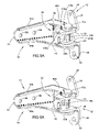
- FIG. 6A is a perspective view of a hinge system according to a sixth embodiment of the present invention.
- the hinge system 10 of the present invention includes a door hinge bracket 12 , pillar hinge bracket 14 , a hinge pin 16 , and a latching device 18 .
- the pillar hinge bracket 14 is adapted to be affixed to a vehicle pillar 20
- the door hinge bracket 12 is adapted to be affixed to a vehicle door 22 .
- the door hinge bracket 12 is rotatably secured to the pillar hinge bracket 14 via the hinge pin 16 and the angular orientation of the door hinge bracket and the door secured thereto may be checked or releasably maintained in any one of two or more positions via interaction of the latching device 18 and one of a plurality of engagement points, as described hereinafter.
- the door hinge bracket 12 is affixable to the vehicle door 22 and includes a first or upper ear 24 extending vertically upward and a second or lower ear 26 extending vertically downward. Each ear 24 , 26 defines a hole 28 and 30 for the passage of a fastener to affix the door hinge bracket 12 to the vehicle door 22 . Integrally formed with the first and second ears 24 , 26 and extending therebetween is a U-shaped intermediate member 32 .
- the pillar hinge bracket 14 is generally L-shaped and includes a pillar flange 50 and a pin bracket 52 .
- the pillar flange 50 has a generally planar base wall 51 from which upper and lower raised peripheral walls 54 a , 54 b extend.
- the pillar flange 50 defines two holes 56 and 58 for the passage of fasteners that affix the pillar hinge bracket 14 to the vehicle pillar 20 .
- the pin bracket 52 is oriented generally perpendicular to the pillar flange 50 and includes a base wall 59 and upper and lower raised peripheral walls 60 a , 60 b .
- the base wall 59 of the pin bracket 52 integrally extends from the base wall 51 of the pillar flange 50 .
- the upper and lower raised peripheral walls 60 a , 60 b of the pin bracket 52 integrally merge with the upper and lower raised peripheral walls 54 a , 54 b , respectively, of the pillar flange 50 , as illustrated.
- the pin bracket base wall 59 is shorter in length than the pin bracket peripheral walls 60 a , 60 b such that the pin bracket peripheral walls 60 a , 60 b extend past the end of the pin bracket base wall 59 , as illustrated.
- the hinge pin 16 includes an enlarged upper head 16 a , a cylindrical body 16 b , and a swaged lower head 16 c .
- the hinge pin 16 has a length, and the cylindrical body 16 b has a diameter, so as to permit the hinge pin 16 to extend through the aligned holes in the pillar bracket 14 and the door bracket 12 , respectively.
- the enlarged upper head 16 a rests upon the upper pin bracket peripheral wall 60 a
- the body 16 b passes through the holes
- the swaged lower head 16 c (which is formed by known riveting or heading techniques on the lower end of the pin body 16 b ), is downwardly adjacent the lower pin bracket peripheral wall 60 b .
- the hinge pin 16 is held in place and cannot be removed without destroying the hinge pin 16 and/or one of the hinge brackets 12 , 14 .
- the hinge pin 16 is held in place so as to be non-rotatably affixed to the pillar hinge bracket 14 , while the door hinge bracket 12 is rotatable about the hinge pin 16 .
- bushings be received in the holes formed in the upper and lower legs 34 , of the U-shaped member 32 of the door hinge bracket 12 . The bushings facilitate rotation of the door hinge bracket 12 about the stationary hinge pin 16 . It is believed that such bushings are well known to those skilled in the art.
- door hinge bracket 12 , pillar hinge bracket 14 , and hinge pin 16 described to this point are generally conventional and well known in the art.
- the various embodiments of the present invention will be described hereinafter as they are used in conjunction with the door hinge bracket 12 , pillar hinge bracket 14 , and hinge pin 16 , modified as described hereinafter.
- FIGS. 1A-1F The first embodiment of the present invention is illustrated in FIGS. 1A-1F , and is described hereinafter.
- the head 16 a of the hinge pin 16 is shown to include first and second raised tabs or protrusions 68 a , 68 b and associated first and second recesses or notches 69 a , 69 b .
- the first and second notches and recesses will hereafter be referred to as the first and second engagement points 70 a , 70 b.
- the latching device 18 includes a lower leg 18 a , an upper bend 18 b curling around a loop of more than 180 degrees, and an upper arm 18 c .
- the lower leg extends through aligned holes formed in the upper and lower legs 34 , 36 of the U-shaped member 32 of the door hinge bracket 12 .
- the upper bend 18 b and the upper arm 18 c are disposed above the upper leg 34 of the door hinge bracket U-shaped member 32 , and adjacent the first or upper ear 24 of the door hinge bracket.
- the latching device 18 is preferably formed from a resilient metal material, such as steel or spring steel, and therefore will inherently exhibit a certain amount of bending or temporary deformation, when appropriate force is applied.
- the present invention takes advantage of that fact in using the latching device 18 to selectively engage the engagement points 70 a , 70 b , which serve as catches to releasably retain the door hinge bracket 12 , and the door affixed thereto, releasably retain the door in any one of two angular orientations.
- the latching device 18 is installed in the door hinge bracket 12 by simply inserting the latching device leg 18 a through the aligned holes formed in the upper and lower legs 34 , 36 of the door hinge bracket U-shaped member 32 . Further, the latching device 18 may be removed after use by simply pulling the latching device 18 out of the door hinge bracket 12 .
- the door hinge bracket 12 and the associated door 20 With the latching device 18 installed in the door hinge bracket 12 , and the leg 18 a in engagement with the first engagement point or catch 70 a (i.e., received in the first recess 69 a ), the door hinge bracket 12 and the associated door 20 is retained or held in the closed position or first orientation.
- the upper end of the latching device leg 18 a which is in engagement with the first tab or protrusion 68 a , deforms so as to permit the latching device 18 to clear the first engagement point 70 a.
- the door hinge bracket 12 continues to rotate (clockwise in FIG. 1D ) until the latching device leg 18 a engages the second tab or protrusion 68 b provided by the second engagement point or catch 70 b .
- the latching device leg 18 a again deforms so as to snap over the second tab 68 b and is received in the second recess 69 b (second engagement point 70 b ), defining the second orientation (open position) of the door hinge bracket 12 and associated door 20 .
- the door 20 and door hinge bracket 12 will be retained in the second orientation or open position until an appropriate closing force is applied to move the door hinge bracket 12 and latching device 18 toward the closed position, at which the latching device leg 18 a will again snap over the first engagement point 70 a.
- FIGS. 2A-2F The second embodiment of the present invention is illustrated in FIGS. 2A-2F , and is described hereinafter.
- the head 16 a of the hinge pin 16 is shown to include first and second recesses or notches 78 a , 78 b and associated first and second radially extending raised tabs or protrusions 79 a , 79 b .
- the first and second notches and recesses will hereafter be referred to as the first and second engagement points 168 a , 168 b.
- the latching device 118 is somewhat J-shaped, and includes a lower leg 118 a , an interconnecting portion 118 b , and an upper arm 118 c .
- the lower leg 118 a extends through aligned holes formed in the upper and lower legs 34 , 36 of the U-shaped member 32 of the door hinge bracket 12 . It is noted that the aligned holes are formed in the upper and lower legs 34 , 36 relatively close to the base 42 , as illustrated best in FIG. 2A .
- the interconnecting portion 118 b extends diagonally across the upper surface of the hinge pin head 16 a such that the upper arm 118 c extends downwardly on the opposite side of the hinge pin head 16 a , and adjacent to the first or upper ear 24 , as shown.
- the latching device 118 is preferably formed from a resilient metal material, such as steel or spring steel, and therefore will inherently exhibit a certain amount of bending or temporary deformation, when appropriate force is applied.
- the present invention takes advantage of that fact in using the latching device 118 to selectively engage the engagement points 168 a , 168 b , which serve as catches to engage the door hinge bracket 12 , and the door affixed thereto, so as to releasably retain the door in any one of two angular orientations.
- the latching device 118 is installed in the door hinge bracket 12 by simply inserting the latching device leg 118 a through the aligned holes formed in the upper and lower legs 34 , 36 of the door hinge bracket U-shaped member 32 . Further, the latching device 118 may be removed after use by simply pulling the latching device 118 out of the door hinge bracket 12 .
- the door hinge bracket 12 and the associated door 20 is retained or held in the closed position or first orientation.
- the upper end of the latching device leg 118 a which is adjacent the interconnecting portion 118 b and in engagement with the first tab or protrusion 79 a , deforms so as to permit the latching device 118 to clear the first engagement point 168 a.
- the door hinge bracket 12 continues to rotate (clockwise in FIG. 2D ) until the latching device leg 118 a engages the second tab or protrusion 79 b provided by the second engagement point or catch 168 b . With continued application of force, the latching device leg 118 a again deforms so as to snap over the second tab 79 b and is received in the second recess 79 b , defining the second orientation (open position) of the door hinge bracket 12 and associated door 20 .
- the door 20 and door hinge bracket 12 will be retained in the second orientation or open position until an appropriate closing force is applied to move the door hinge bracket 12 and latching device 118 toward the closed position, at which the latching device leg 118 a will again snap over the first engagement point 168 a.
- FIGS. 3A-3F The third embodiment of the present invention is illustrated in FIGS. 3A-3F , and is described hereinafter.
- the upper raised peripheral wall 60 a of the pillar hinge bracket 14 is shown to include first and second recesses or notches 178 a , 178 b .
- the first and second notches and recesses may hereafter be referred to as the first and second engagement points 268 a , 268 b.
- the latching device 218 includes a lower leg 218 a , an interconnecting securement portion 218 b , and an upper leg arm 218 c .
- the upper leg 218 c extends through a hole in the upper leg 34 of the U-shaped member 32 of the door hinge bracket 12 .
- the lower leg 218 a extends through a hole formed in the lower leg 36 of the U-shaped member of the door hinge bracket 12 .
- the interconnecting securement portion 218 b which serves as a spring to force or bias the upper and lower legs 218 c , 218 a away from one another, extends across the door hinge bracket 12 and rests against the base 42 , as illustrated.
- the holes formed in the upper and lower legs 34 , 36 are relatively close to the upper and lower ears 24 , 26 , as illustrated best in FIG. 3C .
- the latching device 218 is preferably formed from a resilient metal material, such as steel or spring steel, and therefore will inherently exhibit a certain amount of bending or temporary deformation, when appropriate force is applied.
- the present invention takes advantage of this fact in using the latching device 218 to selectively engage the engagement points 268 a , 268 b , which serve as catches to engage the door hinge bracket 12 , and the door affixed thereto, so as to releasably retain the door in any one of two angular orientations.
- the latching device 218 is installed in the door hinge bracket 12 by simply pinching the interconnecting securement portion 218 b so as to move the lower and upper legs 218 a , 218 c toward one another, inserting the latching device between the upper and lower legs 34 , 36 of the door hinge bracket U-shaped member 32 , aligning the legs 218 a , 218 c with the holes, and releasing the interconnecting securement portion 218 b . Further, the latching device 218 may be removed after use by simply pinching the interconnecting securement portion 218 b , and pulling the latching device 218 out of the door hinge bracket 12 .
- the door hinge bracket 12 and the associated door 20 With the latching device 218 installed in the door hinge bracket 12 , and the upper leg 218 c in engagement with the first engagement point or catch 268 a (i.e., received in the first recess 178 a ), the door hinge bracket 12 and the associated door 20 is retained or held in the closed position or first orientation.
- the upper latching device leg 218 c is forced outwardly away from the centerline of the hinge pin and thereby temporarily deforms to allow the latching device 218 to clear the first engagement point 268 a.
- the door hinge bracket 12 continues to rotate (clockwise in FIG. 3D ) until the latching device upper leg 218 c aligns with the second recess 178 b defining the second engagement point, at which point the upper leg 218 c resiliently snaps inwardly into the second recess 178 b , thereby defining the second orientation (open position) of the door hinge bracket 12 and associated door 20 .
- the door 20 and door hinge bracket 12 will be retained in the second orientation or open position until an appropriate closing force is applied to move the door hinge bracket 12 and latching device 218 toward the closed position, at which the latching device leg 218 c will again snap into the first engagement point 168 a.
- FIGS. 4A-4F The fourth embodiment of the present invention is illustrated in FIGS. 4A-4F , and is described hereinafter.
- the upper raised peripheral wall 60 a of the pillar hinge bracket 14 is shown to include first and second recesses or notches 278 a , 278 b .
- the first and second notches and recesses may hereafter be referred to as the first and second engagement points 368 a , 368 b.
- the latching device 318 includes a body portion 318 a , a depending flange 318 b , and an extending tab 318 c .
- the body portion is secured to the upper ear 24 of the door hinge bracket 12 , preferably with the fastener that secures the door hinge bracket 12 to the door 20 .
- the depending flange 318 b extends from the body portion 318 a and serves as a spring to bias the extending tab 318 c into engagement with the engagement points 368 a , 368 b .
- the latching device 318 is preferably formed from a resilient metal material, such as steel or spring steel, and therefore will inherently exhibit a certain amount of bending or temporary deformation, when appropriate force is applied.
- the present invention takes advantage of this fact in using the latching device 318 to selectively engage the engagement points 368 a , 368 b , which serve as catches to engage the door hinge bracket 12 , and the door affixed thereto, so as to releasably retain the door in any one of two angular orientations.
- the latching device 318 is affixed to the door hinge bracket 12 by using the fastener that secures the door hinge bracket 12 to the door 20 , and is removed by removing the fastener.
- the door hinge bracket 12 and the associated door 20 With the latching device 318 installed on the door hinge bracket 12 , and the tab 318 c in engagement with the first engagement point or catch 368 a (i.e., received in the first recess 278 a ), the door hinge bracket 12 and the associated door 20 is retained or held in the closed position or first orientation. When a sufficient opening force is applied to the door 20 , the tab 318 c is forced against the bias of the flange 318 b , allowing the latching device 318 to clear the first engagement point 368 a.
- the door hinge bracket 12 continues to rotate (clockwise in FIG. 4D ) until the latching device tab 318 c aligns with the second recess 278 b defining the second engagement point 368 b , at which point the tab 318 c resiliently snaps inwardly (i.e., toward the hinge pin centerline) into the second recess 278 b , thereby defining the second orientation (open position) of the door hinge bracket 12 and associated door 20 .
- the door 20 and door hinge bracket 12 will be retained in the second orientation or open position until an appropriate closing force is applied to move the door hinge bracket 12 and latching device 318 toward the closed position, at which the latching device tab 318 c will again snap into the first engagement point 268 a.
- FIGS. 5A-5F The fifth embodiment of the present invention is illustrated in FIGS. 5A-5F , and is described hereinafter.
- the upper raised peripheral wall 60 a of the pillar hinge bracket 14 is shown to include a first notched recess 378 a and a second recess or hole 378 b .
- the first recess is in an edge of the upper peripheral wall 60 a while the second recess is a hole through the upper peripheral wall 60 a , as illustrated.
- the first and second recesses 378 a , 378 b may hereafter be referred to as the first and second engagement points 468 a , 468 b.
- the latching device 418 includes a lower leg 418 a , an interconnecting spring portion 418 b , and an upper leg 418 c .
- the upper leg 418 c extends through a hole in the upper leg 34 of the U-shaped member 32 of the door hinge bracket 12 .
- the lower leg 418 a extends through a hole formed in the lower leg 36 of the U-shaped member 32 of the door hinge bracket 12 .
- the interconnecting spring portion 418 b which serves to force or bias the upper and lower legs 418 c , 418 a away from one another, extends around the hinge pin 16 , as illustrated.
- the holes formed in the upper and lower legs 34 , 36 are relatively close to the base 42 of the U-shaped portion 32 , as illustrated best in FIG. 5C .
- the latching device 418 is preferably formed from a resilient metal material, such as steel or spring steel, and therefore will inherently exhibit a certain amount of bending or temporary deformation, when appropriate force is applied.
- the present invention takes advantage of this fact in using the latching device 418 to selectively engage the engagement points 468 a , 468 b , which serve as catches to engage the door hinge bracket 12 , and the door affixed thereto, so as to releasably retain the door in any one of two angular orientations.
- the latching device 418 is installed in the door hinge bracket 12 by simply pinching the interconnecting spring portion 418 b so as to move the lower and upper legs 418 a , 418 c toward one another, inserting the latching device between the upper and lower legs 34 , 36 of the door hinge bracket U-shaped member 32 , aligning the legs 418 a , 418 c with the holes, and releasing the interconnecting spring portion 418 b .
- the upper leg 418 c will project upwardly from the door hinge upper leg 34 , as shown in FIG. 5E .
- the latching device 418 may be removed after use by simply pinching the spring portion 418 b , and pulling the latching device 418 out of the door hinge bracket 12 .
- the door hinge bracket 12 and the associated door 20 With the latching device 418 installed in the door hinge bracket 12 , and the upper leg 418 c in engagement with the first engagement point or catch 468 a (i.e., received in the first recess 378 a ), the door hinge bracket 12 and the associated door 20 is retained or held in the closed position or first orientation. When a sufficient opening force is applied to the door 20 , the latching device upper leg 418 c is forced downwardly against the bias of the spring portion 418 b , allowing the latching device 418 to clear the first engagement point 468 a.
- the door hinge bracket 12 continues to rotate (clockwise in FIG. 5D ) and the upper leg 418 c slides along the lower surface of the upper peripheral wall 60 a until the latching device upper leg 418 c aligns with the second recess 378 b defining the second engagement point 468 b , at which point the upper leg 418 c resiliently snaps upwardly into the second recess 378 b , thereby defining the second orientation (open position) of the door hinge bracket 12 and associated door 20 .
- the door 20 and door hinge bracket 12 will be retained in the second orientation or open position until an appropriate closing force is applied to move the door hinge bracket 12 and latching device 418 toward the closed position, at which the latching device leg 418 c will again snap into the first engagement point 468 a.
- FIGS. 6A-6F The sixth embodiment of the present invention is illustrated in FIGS. 6A-6F , and is described hereinafter.
- the upper raised peripheral wall 60 a of the pillar hinge bracket 14 is shown to include a first notched recess 378 a and a second recess or hole 378 b .
- the first recess is in an edge of the upper peripheral wall 60 a while the second recess is a hole through the upper peripheral wall 60 a , as illustrated.
- the first and second recesses 378 a , 378 b may hereafter be referred to as the first and second engagement points 468 a , 468 b.
- the latching device 518 includes a lower leg 518 a , an interconnecting coil spring portion 518 b , and an upper leg 518 c .
- the upper leg 518 c extends through a hole in the upper leg 34 of the U-shaped member 32 of the door hinge bracket 12 .
- the lower leg 518 a extends through a hole formed in the lower leg 36 of the U-shaped member 32 of the door hinge bracket 12 .
- the interconnecting coil spring portion 518 b which serves to force or bias the upper and lower legs 518 c , 518 a away from one another, extends adjacent to the hinge pin 16 , as illustrated.
- the holes formed in the upper and lower legs 34 , 36 are relatively close to the base 42 of the U-shaped portion 32 , as illustrated best in FIG. 6C .
- the latching device 518 is preferably formed from a resilient metal material, such as steel or spring steel, and therefore will inherently exhibit a certain amount of bending or temporary deformation, when appropriate force is applied.
- the present invention takes advantage of this fact in using the latching device 518 to selectively engage the engagement points 468 a , 468 b , which serve as catches to engage the door hinge bracket 12 , and the door affixed thereto, so as to releasably retain the door in any one of two angular orientations.
- the latching device 518 is installed in the door hinge bracket 12 by simply pinching the interconnecting coil spring portion 518 b so as to move the lower and upper legs 518 a , 518 c toward one another, inserting the latching device between the upper and lower legs 34 , 36 of the door hinge bracket U-shaped member 32 , aligning the legs 518 a , 518 c with the holes, and releasing the interconnecting coil spring portion 518 b .
- the upper leg 518 c will project upwardly from the door hinge upper leg 34 , as shown in FIG. 6E .
- the latching device 518 may be removed after use by simply pinching the coil spring portion 518 b , and pulling the latching device 518 out of the door hinge bracket 12 .
- the door hinge bracket 12 and the associated door 20 With the latching device 518 installed in the door hinge bracket 12 , and the upper leg 518 c in engagement with the first engagement point or catch 468 a (i.e., received in the first recess 378 a ), the door hinge bracket 12 and the associated door 20 is retained or held in the closed position or first orientation. When a sufficient opening force is applied to the door 20 , the latching device upper leg 518 c is forced downwardly against the bias of the coil spring portion 518 b , allowing the latching device 518 to clear the first engagement point 468 a.
- the door hinge bracket 12 continues to rotate (clockwise in FIG. 6D ) and the upper leg 518 c slides along the lower surface of the upper peripheral wall 60 a until the latching device upper leg 518 c aligns with the second recess 378 b defining the second engagement point 468 b , at which point the upper leg 518 c resiliently snaps upwardly into the second recess 378 b , thereby defining the second orientation (open position) of the door hinge bracket 12 and associated door 20 .
- the door 20 and door hinge bracket 12 will be retained in the second orientation or open position until an appropriate closing force is applied to move the door hinge bracket 12 and latching device 518 toward the closed position, at which the latching device leg 518 c will again snap into the first engagement point 468 a.
- the latching devices described herein may be formed from any number of materials.
- the latching device 18 is formed from a metal material (i.e., steel, spring steel) that will provide the desired spring-like effect. Similar effects can be achieved should the latching device 18 be formed from plastic, or a combination of steel and plastic. It is currently believed that a metal material will be preferred for reasons of cost, durability, and ease of manufacture.
- the latching devices described herein work efficiently as part of a hinge system 10 upon a vehicle.
- the hinge system is manufactured with both the door hinge bracket 12 and pillar hinge bracket 14 receiving the hinge pin 16 .
- This hinge system 10 is adapted for use during intermediate vehicle assembly and especially during a painting operation wherein the doors 48 or door hinge brackets 12 must be moved between a first position or angular orientation relative to the vehicle body and a second position or angular orientation relative to the vehicle body, as described hereinbefore.
- first and second orientations may be different than the open and closed positions illustrated, and that intermediate angular positions in which the door may be retained may easily be added by introducing further engagement points between the two engagement points illustrated in the drawings.
- open position and closed positions are relative terms, and while the closed position will ordinarily be a fully closed position, the open position may be an angular orientation short of the ‘full open’ position.
Landscapes
- Engineering & Computer Science (AREA)
- Mechanical Engineering (AREA)
- Hinge Accessories (AREA)
Abstract
An integrated hinge system that provides for temporary checking of a vehicle door is provided, the system including a hinge pin, a door hinge bracket, a pillar hinge bracket, and a latching device. The latching device is releasably affixed to the door hinge bracket and rotates with the door hinge bracket relative to the hinge pin and the pillar bracket. One of the hinge pin and the pillar bracket define engagement points that the latching device engages to releasably retain the door hinge bracket in any one of at least two angular orientations relative to the pillar hinge bracket.
Description
The disclosure of U.S. patent application Ser. No. 10/878,761, filed Jun. 28, 2004, is expressly incorporated herein by reference in its entirety.
During the manufacture and assembly of vehicles, it is often necessary to perform certain operations with the vehicle body and doors assembled. Automated application of sealer to body joints and door joints and painting of the vehicle are examples of such operations. Concurrent door and body painting provides uniform color and quality between the body and doors. During the sealing and painting operations, the vehicle door must be opened and closed numerous times. Because the painting, etc. is often performed by automated systems, position and repeatability of locating the doors is of primary importance.
Door hinges used on the finished vehicle may also be used during these intermediate assembly steps such as painting. However, the permanent door checking devices used on the finished vehicle typically are not in place during these intermediate steps because they can be damaged by the harsh environment in paint operations (ovens, paint, use of electrostatic equipment, solvents, and/or preparatory cleaners). As a substitute, temporary door checking devices are used to hold doors in desired positions during these intermediate steps. Typically, a temporary checking device is affixed to the door and vehicle body before the operation begins and removed after the operation is complete and often reused. The temporary checking device may be positioned at the same location in which the permanent door checking device used on the finished vehicle will be placed.
Because most temporary checking devices are self contained, requiring nothing except a place to be mounted, they tend to be relatively complex and time consuming to install and remove. This increases overall vehicle manufacturing costs. What is desired is a temporary checking device that works in conjunction with elements already in place on the vehicle, the temporary checking device being simple and easily installed and removed.
The present invention provides an improvement over the prior art by providing a temporary checking device that works in conjunction with elements of a vehicle hinge that will remain in the vehicle's final configuration. Moreover, the checking device is simpler and more easily installed and removed than the door checkers known in the art.
In accordance with the present invention, a hinge system is provided that includes a hinge pin, a door hinge bracket receiving the hinge pin, a pillar hinge bracket also receiving the hinge pin, and a latching device secured to one of the door hinge bracket and operable to selectively engage any one of a plurality of engagement points. The door hinge bracket is rotatably movable with respect to the pillar hinge bracket. The latching device, which is releasably affixed to the door hinge bracket and moves therewith, includes a head selectively engageable with the engagement points during movement of the door hinge bracket relative to the pillar hinge bracket and the hinge pin. Interaction between the latching device and the engagement points provides locations in which the door hinge bracket, and thus the door secured thereto, may be temporarily checked or stopped with respect to the pillar hinge bracket (i.e., the vehicle body) so that the door may be releasably maintained in a desired angular orientation (degree of opening).
In accordance with one aspect of the invention, the engagement points are provided on a head of the hinge pin. In accordance with another aspect of the invention, the engagement points are provided on the pillar hinge bracket.
These and further features of the invention will be apparent with reference to the following description and drawings, wherein:
With reference to FIG. 1A , the hinge system 10 of the present invention includes a door hinge bracket 12, pillar hinge bracket 14, a hinge pin 16, and a latching device 18. Although only illustrated in a cursory fashion in FIG. 1A , it is considered apparent that the pillar hinge bracket 14 is adapted to be affixed to a vehicle pillar 20, and the door hinge bracket 12 is adapted to be affixed to a vehicle door 22.
The door hinge bracket 12 is rotatably secured to the pillar hinge bracket 14 via the hinge pin 16 and the angular orientation of the door hinge bracket and the door secured thereto may be checked or releasably maintained in any one of two or more positions via interaction of the latching device 18 and one of a plurality of engagement points, as described hereinafter.
The door hinge bracket 12 is affixable to the vehicle door 22 and includes a first or upper ear 24 extending vertically upward and a second or lower ear 26 extending vertically downward. Each ear 24, 26 defines a hole 28 and 30 for the passage of a fastener to affix the door hinge bracket 12 to the vehicle door 22. Integrally formed with the first and second ears 24, 26 and extending therebetween is a U-shaped intermediate member 32.
The U-shaped intermediate member 32 has an upper leg 34, a lower leg 36, and a base 42 interconnecting the upper and lower legs 34, 36. The upper leg 34 extends between and interconnects the upper ear 24 and the base 42. The lower leg 36 extends between and interconnects the lower ear 26 and the base 42. Each leg 34 and 36 of the U-shaped member defines a hole through which the hinge pin 16 extends.
The pillar hinge bracket 14 is generally L-shaped and includes a pillar flange 50 and a pin bracket 52. The pillar flange 50 has a generally planar base wall 51 from which upper and lower raised peripheral walls 54 a, 54 b extend. The pillar flange 50 defines two holes 56 and 58 for the passage of fasteners that affix the pillar hinge bracket 14 to the vehicle pillar 20.
The pin bracket 52 is oriented generally perpendicular to the pillar flange 50 and includes a base wall 59 and upper and lower raised peripheral walls 60 a, 60 b. The base wall 59 of the pin bracket 52 integrally extends from the base wall 51 of the pillar flange 50. The upper and lower raised peripheral walls 60 a, 60 b of the pin bracket 52 integrally merge with the upper and lower raised peripheral walls 54 a, 54 b, respectively, of the pillar flange 50, as illustrated. Preferably, the pin bracket base wall 59 is shorter in length than the pin bracket peripheral walls 60 a, 60 b such that the pin bracket peripheral walls 60 a, 60 b extend past the end of the pin bracket base wall 59, as illustrated.
Each of the upper and lower pin bracket peripheral walls 60 a, 60 b define a hole near their distal ends. When the hinge system 10 is assembled, the holes defined by the pin bracket peripheral walls 60 a, 60 b align with the holes formed in the upper and lower legs 34, 36 of the U-shaped member 32 of the door hinge bracket 12 and cooperate to receive the hinge pin 16.
The hinge pin 16 includes an enlarged upper head 16 a, a cylindrical body 16 b, and a swaged lower head 16 c. The hinge pin 16 has a length, and the cylindrical body 16 b has a diameter, so as to permit the hinge pin 16 to extend through the aligned holes in the pillar bracket 14 and the door bracket 12, respectively. As such, the enlarged upper head 16 a rests upon the upper pin bracket peripheral wall 60 a, the body 16 b passes through the holes and the swaged lower head 16 c (which is formed by known riveting or heading techniques on the lower end of the pin body 16 b), is downwardly adjacent the lower pin bracket peripheral wall 60 b. As such, the hinge pin 16 is held in place and cannot be removed without destroying the hinge pin 16 and/or one of the hinge brackets 12, 14.
Preferably, and as will be described more fully hereinafter, the hinge pin 16 is held in place so as to be non-rotatably affixed to the pillar hinge bracket 14, while the door hinge bracket 12 is rotatable about the hinge pin 16. Although not illustrated, it is preferred that bushings be received in the holes formed in the upper and lower legs 34, of the U-shaped member 32 of the door hinge bracket 12. The bushings facilitate rotation of the door hinge bracket 12 about the stationary hinge pin 16. It is believed that such bushings are well known to those skilled in the art.
Numerous means for fixing the hinge pin 16 to the pillar hinge bracket 14 are known in the art and can be used interchangeably with the present structure. Such known means include splines, non-circular cross-sectional profiles (i.e., D-shaped cross sections at upper end of the hinge pin body 16 b and the hole in the upper pin bracket peripheral wall 60 a), and crimping the hinge pin 16 to the pillar hinge bracket 14.
It is noted that the door hinge bracket 12, pillar hinge bracket 14, and hinge pin 16 described to this point are generally conventional and well known in the art. The various embodiments of the present invention will be described hereinafter as they are used in conjunction with the door hinge bracket 12, pillar hinge bracket 14, and hinge pin 16, modified as described hereinafter.
The first embodiment of the present invention is illustrated in FIGS. 1A-1F , and is described hereinafter.
With reference to FIGS. 1B-1E , the head 16 a of the hinge pin 16 is shown to include first and second raised tabs or protrusions 68 a, 68 b and associated first and second recesses or notches 69 a, 69 b. The first and second notches and recesses will hereafter be referred to as the first and second engagement points 70 a, 70 b.
With reference to FIG. 1F , the latching device 18 includes a lower leg 18 a, an upper bend 18 b curling around a loop of more than 180 degrees, and an upper arm 18 c. The lower leg extends through aligned holes formed in the upper and lower legs 34, 36 of the U-shaped member 32 of the door hinge bracket 12. The upper bend 18 b and the upper arm 18 c are disposed above the upper leg 34 of the door hinge bracket U-shaped member 32, and adjacent the first or upper ear 24 of the door hinge bracket. It will be appreciated that the latching device 18 is preferably formed from a resilient metal material, such as steel or spring steel, and therefore will inherently exhibit a certain amount of bending or temporary deformation, when appropriate force is applied. The present invention takes advantage of that fact in using the latching device 18 to selectively engage the engagement points 70 a, 70 b, which serve as catches to releasably retain the door hinge bracket 12, and the door affixed thereto, releasably retain the door in any one of two angular orientations.
The latching device 18 is installed in the door hinge bracket 12 by simply inserting the latching device leg 18 a through the aligned holes formed in the upper and lower legs 34, 36 of the door hinge bracket U-shaped member 32. Further, the latching device 18 may be removed after use by simply pulling the latching device 18 out of the door hinge bracket 12.
With the latching device 18 installed in the door hinge bracket 12, and the leg 18 a in engagement with the first engagement point or catch 70 a (i.e., received in the first recess 69 a), the door hinge bracket 12 and the associated door 20 is retained or held in the closed position or first orientation. When a sufficient opening force is applied to the door 20, the upper end of the latching device leg 18 a, which is in engagement with the first tab or protrusion 68 a, deforms so as to permit the latching device 18 to clear the first engagement point 70 a.
Once the latching device 18 is clear of the first engagement point 70 a, the door hinge bracket 12 continues to rotate (clockwise in FIG. 1D ) until the latching device leg 18 a engages the second tab or protrusion 68 b provided by the second engagement point or catch 70 b. With continued application of force, the latching device leg 18 a again deforms so as to snap over the second tab 68 b and is received in the second recess 69 b (second engagement point 70 b), defining the second orientation (open position) of the door hinge bracket 12 and associated door 20. The door 20 and door hinge bracket 12 will be retained in the second orientation or open position until an appropriate closing force is applied to move the door hinge bracket 12 and latching device 18 toward the closed position, at which the latching device leg 18 a will again snap over the first engagement point 70 a.
The second embodiment of the present invention is illustrated in FIGS. 2A-2F , and is described hereinafter.
With reference to FIGS. 2B-2E , the head 16 a of the hinge pin 16 is shown to include first and second recesses or notches 78 a, 78 b and associated first and second radially extending raised tabs or protrusions 79 a, 79 b. The first and second notches and recesses will hereafter be referred to as the first and second engagement points 168 a, 168 b.
With reference to FIG. 2F , the latching device 118 is somewhat J-shaped, and includes a lower leg 118 a, an interconnecting portion 118 b, and an upper arm 118 c. The lower leg 118 a extends through aligned holes formed in the upper and lower legs 34, 36 of the U-shaped member 32 of the door hinge bracket 12. It is noted that the aligned holes are formed in the upper and lower legs 34, 36 relatively close to the base 42, as illustrated best in FIG. 2A . The interconnecting portion 118 b extends diagonally across the upper surface of the hinge pin head 16 a such that the upper arm 118 c extends downwardly on the opposite side of the hinge pin head 16 a, and adjacent to the first or upper ear 24, as shown. It will be appreciated that the latching device 118 is preferably formed from a resilient metal material, such as steel or spring steel, and therefore will inherently exhibit a certain amount of bending or temporary deformation, when appropriate force is applied. The present invention takes advantage of that fact in using the latching device 118 to selectively engage the engagement points 168 a, 168 b, which serve as catches to engage the door hinge bracket 12, and the door affixed thereto, so as to releasably retain the door in any one of two angular orientations.
The latching device 118 is installed in the door hinge bracket 12 by simply inserting the latching device leg 118 a through the aligned holes formed in the upper and lower legs 34, 36 of the door hinge bracket U-shaped member 32. Further, the latching device 118 may be removed after use by simply pulling the latching device 118 out of the door hinge bracket 12.
With the latching device 118 installed in the door hinge bracket 12, and the leg 118 a in engagement with the first engagement point or catch 168 a (i.e., received in the first recess 78 a), the door hinge bracket 12 and the associated door 20 is retained or held in the closed position or first orientation. When a sufficient opening force is applied to the door 20, the upper end of the latching device leg 118 a, which is adjacent the interconnecting portion 118 b and in engagement with the first tab or protrusion 79 a, deforms so as to permit the latching device 118 to clear the first engagement point 168 a.
Once the latching device 118 is clear of the first engagement point 168 a, the door hinge bracket 12 continues to rotate (clockwise in FIG. 2D ) until the latching device leg 118 a engages the second tab or protrusion 79 b provided by the second engagement point or catch 168 b. With continued application of force, the latching device leg 118 a again deforms so as to snap over the second tab 79 b and is received in the second recess 79 b, defining the second orientation (open position) of the door hinge bracket 12 and associated door 20. The door 20 and door hinge bracket 12 will be retained in the second orientation or open position until an appropriate closing force is applied to move the door hinge bracket 12 and latching device 118 toward the closed position, at which the latching device leg 118 a will again snap over the first engagement point 168 a.
The third embodiment of the present invention is illustrated in FIGS. 3A-3F , and is described hereinafter.
With reference to FIGS. 3B-3E , the upper raised peripheral wall 60 a of the pillar hinge bracket 14 is shown to include first and second recesses or notches 178 a, 178 b. The first and second notches and recesses may hereafter be referred to as the first and second engagement points 268 a, 268 b.
With reference to FIG. 3F , the latching device 218 includes a lower leg 218 a, an interconnecting securement portion 218 b, and an upper leg arm 218 c. The upper leg 218 c extends through a hole in the upper leg 34 of the U-shaped member 32 of the door hinge bracket 12. The lower leg 218 a extends through a hole formed in the lower leg 36 of the U-shaped member of the door hinge bracket 12. The interconnecting securement portion 218 b, which serves as a spring to force or bias the upper and lower legs 218 c, 218 a away from one another, extends across the door hinge bracket 12 and rests against the base 42, as illustrated. It is noted that the holes formed in the upper and lower legs 34, 36 are relatively close to the upper and lower ears 24, 26, as illustrated best in FIG. 3C . It will be appreciated that the latching device 218 is preferably formed from a resilient metal material, such as steel or spring steel, and therefore will inherently exhibit a certain amount of bending or temporary deformation, when appropriate force is applied. The present invention takes advantage of this fact in using the latching device 218 to selectively engage the engagement points 268 a, 268 b, which serve as catches to engage the door hinge bracket 12, and the door affixed thereto, so as to releasably retain the door in any one of two angular orientations.
The latching device 218 is installed in the door hinge bracket 12 by simply pinching the interconnecting securement portion 218 b so as to move the lower and upper legs 218 a, 218 c toward one another, inserting the latching device between the upper and lower legs 34, 36 of the door hinge bracket U-shaped member 32, aligning the legs 218 a, 218 c with the holes, and releasing the interconnecting securement portion 218 b. Further, the latching device 218 may be removed after use by simply pinching the interconnecting securement portion 218 b, and pulling the latching device 218 out of the door hinge bracket 12.
With the latching device 218 installed in the door hinge bracket 12, and the upper leg 218 c in engagement with the first engagement point or catch 268 a (i.e., received in the first recess 178 a), the door hinge bracket 12 and the associated door 20 is retained or held in the closed position or first orientation. When a sufficient opening force is applied to the door 20, the upper latching device leg 218 c is forced outwardly away from the centerline of the hinge pin and thereby temporarily deforms to allow the latching device 218 to clear the first engagement point 268 a.
Once the latching device 218 is clear of the first engagement point 268 a, the door hinge bracket 12 continues to rotate (clockwise in FIG. 3D ) until the latching device upper leg 218 c aligns with the second recess 178 b defining the second engagement point, at which point the upper leg 218 c resiliently snaps inwardly into the second recess 178 b, thereby defining the second orientation (open position) of the door hinge bracket 12 and associated door 20. The door 20 and door hinge bracket 12 will be retained in the second orientation or open position until an appropriate closing force is applied to move the door hinge bracket 12 and latching device 218 toward the closed position, at which the latching device leg 218 c will again snap into the first engagement point 168 a.
The fourth embodiment of the present invention is illustrated in FIGS. 4A-4F , and is described hereinafter.
With reference to FIGS. 4B-4E , the upper raised peripheral wall 60 a of the pillar hinge bracket 14 is shown to include first and second recesses or notches 278 a, 278 b. The first and second notches and recesses may hereafter be referred to as the first and second engagement points 368 a, 368 b.
With reference to FIG. 4F , the latching device 318 includes a body portion 318 a, a depending flange 318 b, and an extending tab 318 c. The body portion is secured to the upper ear 24 of the door hinge bracket 12, preferably with the fastener that secures the door hinge bracket 12 to the door 20. The depending flange 318 b extends from the body portion 318 a and serves as a spring to bias the extending tab 318 c into engagement with the engagement points 368 a, 368 b. It will be appreciated that the latching device 318 is preferably formed from a resilient metal material, such as steel or spring steel, and therefore will inherently exhibit a certain amount of bending or temporary deformation, when appropriate force is applied. The present invention takes advantage of this fact in using the latching device 318 to selectively engage the engagement points 368 a, 368 b, which serve as catches to engage the door hinge bracket 12, and the door affixed thereto, so as to releasably retain the door in any one of two angular orientations.
The latching device 318 is affixed to the door hinge bracket 12 by using the fastener that secures the door hinge bracket 12 to the door 20, and is removed by removing the fastener.
With the latching device 318 installed on the door hinge bracket 12, and the tab 318 c in engagement with the first engagement point or catch 368 a (i.e., received in the first recess 278 a), the door hinge bracket 12 and the associated door 20 is retained or held in the closed position or first orientation. When a sufficient opening force is applied to the door 20, the tab 318 c is forced against the bias of the flange 318 b, allowing the latching device 318 to clear the first engagement point 368 a.
Once the latching device 318 is clear of the first engagement point 368 a, the door hinge bracket 12 continues to rotate (clockwise in FIG. 4D ) until the latching device tab 318 c aligns with the second recess 278 b defining the second engagement point 368 b, at which point the tab 318 c resiliently snaps inwardly (i.e., toward the hinge pin centerline) into the second recess 278 b, thereby defining the second orientation (open position) of the door hinge bracket 12 and associated door 20. The door 20 and door hinge bracket 12 will be retained in the second orientation or open position until an appropriate closing force is applied to move the door hinge bracket 12 and latching device 318 toward the closed position, at which the latching device tab 318 c will again snap into the first engagement point 268 a.
The fifth embodiment of the present invention is illustrated in FIGS. 5A-5F , and is described hereinafter.
With reference to FIGS. 5B-5E , the upper raised peripheral wall 60 a of the pillar hinge bracket 14 is shown to include a first notched recess 378 a and a second recess or hole 378 b. The first recess is in an edge of the upper peripheral wall 60 a while the second recess is a hole through the upper peripheral wall 60 a, as illustrated. The first and second recesses 378 a, 378 b may hereafter be referred to as the first and second engagement points 468 a, 468 b.
With reference to FIG. 5F , the latching device 418 includes a lower leg 418 a, an interconnecting spring portion 418 b, and an upper leg 418 c. The upper leg 418 c extends through a hole in the upper leg 34 of the U-shaped member 32 of the door hinge bracket 12. The lower leg 418 a extends through a hole formed in the lower leg 36 of the U-shaped member 32 of the door hinge bracket 12. The interconnecting spring portion 418 b, which serves to force or bias the upper and lower legs 418 c, 418 a away from one another, extends around the hinge pin 16, as illustrated. It is noted that the holes formed in the upper and lower legs 34, 36 are relatively close to the base 42 of the U-shaped portion 32, as illustrated best in FIG. 5C . It will be appreciated that the latching device 418 is preferably formed from a resilient metal material, such as steel or spring steel, and therefore will inherently exhibit a certain amount of bending or temporary deformation, when appropriate force is applied. The present invention takes advantage of this fact in using the latching device 418 to selectively engage the engagement points 468 a, 468 b, which serve as catches to engage the door hinge bracket 12, and the door affixed thereto, so as to releasably retain the door in any one of two angular orientations.
The latching device 418 is installed in the door hinge bracket 12 by simply pinching the interconnecting spring portion 418 b so as to move the lower and upper legs 418 a, 418 c toward one another, inserting the latching device between the upper and lower legs 34, 36 of the door hinge bracket U-shaped member 32, aligning the legs 418 a, 418 c with the holes, and releasing the interconnecting spring portion 418 b. The upper leg 418 c will project upwardly from the door hinge upper leg 34, as shown in FIG. 5E . Further, the latching device 418 may be removed after use by simply pinching the spring portion 418 b, and pulling the latching device 418 out of the door hinge bracket 12.
With the latching device 418 installed in the door hinge bracket 12, and the upper leg 418 c in engagement with the first engagement point or catch 468 a (i.e., received in the first recess 378 a), the door hinge bracket 12 and the associated door 20 is retained or held in the closed position or first orientation. When a sufficient opening force is applied to the door 20, the latching device upper leg 418 c is forced downwardly against the bias of the spring portion 418 b, allowing the latching device 418 to clear the first engagement point 468 a.
Once the latching device 418 is clear of the first engagement point 468 a, the door hinge bracket 12 continues to rotate (clockwise in FIG. 5D ) and the upper leg 418 c slides along the lower surface of the upper peripheral wall 60 a until the latching device upper leg 418 c aligns with the second recess 378 b defining the second engagement point 468 b, at which point the upper leg 418 c resiliently snaps upwardly into the second recess 378 b, thereby defining the second orientation (open position) of the door hinge bracket 12 and associated door 20. The door 20 and door hinge bracket 12 will be retained in the second orientation or open position until an appropriate closing force is applied to move the door hinge bracket 12 and latching device 418 toward the closed position, at which the latching device leg 418 c will again snap into the first engagement point 468 a.
The sixth embodiment of the present invention is illustrated in FIGS. 6A-6F , and is described hereinafter.
With reference to FIGS. 6B-6E , the upper raised peripheral wall 60 a of the pillar hinge bracket 14 is shown to include a first notched recess 378 a and a second recess or hole 378 b. The first recess is in an edge of the upper peripheral wall 60 a while the second recess is a hole through the upper peripheral wall 60 a, as illustrated. The first and second recesses 378 a, 378 b may hereafter be referred to as the first and second engagement points 468 a, 468 b.
With reference to FIG. 6F , the latching device 518 includes a lower leg 518 a, an interconnecting coil spring portion 518 b, and an upper leg 518 c. The upper leg 518 c extends through a hole in the upper leg 34 of the U-shaped member 32 of the door hinge bracket 12. The lower leg 518 a extends through a hole formed in the lower leg 36 of the U-shaped member 32 of the door hinge bracket 12. The interconnecting coil spring portion 518 b, which serves to force or bias the upper and lower legs 518 c, 518 a away from one another, extends adjacent to the hinge pin 16, as illustrated. It is noted that the holes formed in the upper and lower legs 34, 36 are relatively close to the base 42 of the U-shaped portion 32, as illustrated best in FIG. 6C . It will be appreciated that the latching device 518 is preferably formed from a resilient metal material, such as steel or spring steel, and therefore will inherently exhibit a certain amount of bending or temporary deformation, when appropriate force is applied. The present invention takes advantage of this fact in using the latching device 518 to selectively engage the engagement points 468 a, 468 b, which serve as catches to engage the door hinge bracket 12, and the door affixed thereto, so as to releasably retain the door in any one of two angular orientations.
The latching device 518 is installed in the door hinge bracket 12 by simply pinching the interconnecting coil spring portion 518 b so as to move the lower and upper legs 518 a, 518 c toward one another, inserting the latching device between the upper and lower legs 34, 36 of the door hinge bracket U-shaped member 32, aligning the legs 518 a, 518 c with the holes, and releasing the interconnecting coil spring portion 518 b. The upper leg 518 c will project upwardly from the door hinge upper leg 34, as shown in FIG. 6E . Further, the latching device 518 may be removed after use by simply pinching the coil spring portion 518 b, and pulling the latching device 518 out of the door hinge bracket 12.
With the latching device 518 installed in the door hinge bracket 12, and the upper leg 518 c in engagement with the first engagement point or catch 468 a (i.e., received in the first recess 378 a), the door hinge bracket 12 and the associated door 20 is retained or held in the closed position or first orientation. When a sufficient opening force is applied to the door 20, the latching device upper leg 518 c is forced downwardly against the bias of the coil spring portion 518 b, allowing the latching device 518 to clear the first engagement point 468 a.
Once the latching device 518 is clear of the first engagement point 468 a, the door hinge bracket 12 continues to rotate (clockwise in FIG. 6D ) and the upper leg 518 c slides along the lower surface of the upper peripheral wall 60 a until the latching device upper leg 518 c aligns with the second recess 378 b defining the second engagement point 468 b, at which point the upper leg 518 c resiliently snaps upwardly into the second recess 378 b, thereby defining the second orientation (open position) of the door hinge bracket 12 and associated door 20. The door 20 and door hinge bracket 12 will be retained in the second orientation or open position until an appropriate closing force is applied to move the door hinge bracket 12 and latching device 518 toward the closed position, at which the latching device leg 518 c will again snap into the first engagement point 468 a.
The latching devices described herein may be formed from any number of materials. Preferably, the latching device 18 is formed from a metal material (i.e., steel, spring steel) that will provide the desired spring-like effect. Similar effects can be achieved should the latching device 18 be formed from plastic, or a combination of steel and plastic. It is currently believed that a metal material will be preferred for reasons of cost, durability, and ease of manufacture.
The latching devices described herein work efficiently as part of a hinge system 10 upon a vehicle. The hinge system is manufactured with both the door hinge bracket 12 and pillar hinge bracket 14 receiving the hinge pin 16. As noted hereinbefore, there is no relative motion between the pillar hinge bracket 14 and the hinge pin 16. Rather, the door hinge bracket 12 is free to move with respect to the hinge pin 16 and the pillar hinge bracket 14.
This hinge system 10 is adapted for use during intermediate vehicle assembly and especially during a painting operation wherein the doors 48 or door hinge brackets 12 must be moved between a first position or angular orientation relative to the vehicle body and a second position or angular orientation relative to the vehicle body, as described hereinbefore.
It is further believed that the first and second orientations may be different than the open and closed positions illustrated, and that intermediate angular positions in which the door may be retained may easily be added by introducing further engagement points between the two engagement points illustrated in the drawings. It is further noted that the open position and closed positions are relative terms, and while the closed position will ordinarily be a fully closed position, the open position may be an angular orientation short of the ‘full open’ position.
Although the invention has been shown and described with reference to certain preferred and alternate embodiments, the invention is not limited to these specific embodiments. Minor variations and insubstantial differences in the various combinations of materials and methods of application may occur to those of ordinary skill in the art while remaining within the scope of the invention as claimed and equivalents.
Claims (13)
1. A hinge system that is adapted to releasably retain a vehicle door in a desired angular orientation on a vehicle body, comprising:
a pillar hinge bracket adapted to be secured to the vehicle body;
a door hinge bracket adapted to be secured to the vehicle door, said door hinge bracket being movable between a first angular orientation relative to said pillar hinge bracket and a second angular orientation relative to said pillar hinge bracket;
a hinge pin having a generally circular head, said hinge pin extending through the pillar hinge bracket and the door hinge bracket and relative to which the door hinge bracket is rotatable;
at least first and second engagement points provided on the generally circular head of said hinge pin, wherein between the engagement points, the perimeter of the head of the hinge pin has a consistent radius that is generally equivalent to the radius of the remainder of the perimeter of the head; and,
a latching device including a first straight portion, a second straight portion transverse to the first straight portion, and an intermediate portion located therebetween that curls around a loop of more than 180 degrees, said latching device first straight portion being releasably affixed to said door hinge bracket and being releasably engageable with any of said at least first and second engagement points so as to releasably retain said door hinge bracket, and said vehicle door secured thereto, in said first and second angular orientations and said second straight portion abutting the door bracket.
2. The hinge system according to claim 1 , wherein said door hinge bracket includes an upper ear and a lower ear that are adapted to be secured to the vehicle door, and wherein said latching device is releasably secured to at least one of said upper and lower ears.
3. A hinge system that is adapted to releasably retain a vehicle door in a desired angular orientation on a vehicle body, comprising:
a pillar hinge bracket adapted to be secured to the vehicle body;
a door hinge bracket adapted to be secured to the vehicle door, said door hinge bracket being movable between a first angular orientation relative to said pillar hinge bracket and a second angular orientation relative to said pillar hinge bracket;
a hinge pin extending through the pillar hinge bracket and the door hinge bracket and relative to which the door hinge bracket is rotatable;
at least first and second engagement points provided on a head of said hinge pin; and,
a latching device comprising a straight portion that terminates one end of the latching device, said latching device being releasably affixed to said door hinge bracket and being releasably engageable with any of said at least first and second engagement points so as to releasably retain said door hinge bracket, and said vehicle door secured thereto, in said first and second angular orientations; and
wherein said door hinge bracket includes first and second mounting ears and a U-shaped intermediate member extending between and interconnecting the first and second mounting ears, wherein the U-shaped intermediate member includes an upper leg and a lower leg and a base extending between a first end of the upper leg and a first end of the lower leg and wherein the first mounting ear projects from a second end of the upper leg and the second mounting ear projects from a second end of the lower leg,
wherein the straight portion of the latching device is received within apertures in both said upper and said lower legs and projects from at least one of the upper and lower legs, and
said hinge pin extends through openings in said upper and lower legs, and wherein said latching device is releasably secured to at least one of said upper and lower legs and projects from said at least one upper and lower legs.
4. The hinge system of claim 3 , wherein the latching device further comprises a second straight portion parallel to the first straight portion and an intermediate portion between and transverse to the first and second straight portions.
5. A method of using a door hinge assembly to selectively releasably retain a door in any one of a plurality of positions relative to a vehicle body, wherein said door hinge assembly includes a pillar hinge bracket, a door hinge bracket that includes first and second mounting ears and a U-shaped intermediate member extending between and interconnecting the first and second mounting ears, a hinge pin affixed to said pillar hinge bracket and about which said door hinge bracket rotates, and a latching device including a first straight latching portion and a second straight portion transverse to the first straight portion and an intermediate portion located therebetween that curls around a loop of more than 180 degrees, wherein one of the hinge pin and the pillar hinge bracket defines at least two engagement points that are adapted to selectively receive said latching portion, comprising the steps of:
engaging said latching portion with a first of said at least two engagement points so as to releasably retain said door and said door hinge bracket in a first angular orientation relative to said vehicle body;
applying a force to said door and thereby causing said latching portion to move away from said first of said at least two engagement points and toward a second of said at least two engagement points while rotating said door hinge bracket about said hinge pin, wherein the engagement points are provided on a head of said hinge pin and said latching portion slidably rides over an exterior surface of said hinge pin head as said door is rotated from said first angular orientation toward a second angular orientation; and,
continuing to apply force to said door and thereby causing said latching portion to engage said second of said at least two engagement points and thereby releasably retain said door and said door hinge bracket in said second angular orientation relative to said vehicle.
6. The method according to claim 5 , wherein said first angular orientation is a closed position of said door and said second angular orientation is an open position of said door.
7. The method according to claim 6 , wherein said engagement points are each a recess and said latching portion is receivable in one of said recesses.
8. The method according to claim 6 , wherein said latching device includes a biasing engagement portion that urges said latching portion into engagement with said hinge pin head.
9. The method according to claim 8 , wherein said latching device is releasably affixed to said door hinge bracket.
10. The method according to claim 5 , wherein said engagement points are each a recess and said latching portion is receivable in one of said recesses.
11. The method according to claim 5 , wherein said latching device includes a biasing engagement portion that urges said latching portion into engagement with said hinge pin head.
12. The method according to claim 11 , wherein said latching device is releasably affixed to said door hinge bracket.
13. A method of assembling a hinge assembly comprising a door hinge bracket, a pillar hinge bracket, a hinge pin, and a latching device, comprising the steps of:
aligning openings in said door hinge bracket, said pillar hinge bracket;
inserting said hinge pin through said aligned openings;
securing said hinge pin to said pillar hinge bracket such that said hinge pin and pillar hinge bracket are immovably affixed to one another;
securing said hinge pin to said door hinge bracket such that said door hinge bracket is rotatable about said hinge pin;
securing said latching device to said door hinge bracket such that said latching device moves with said door hinge bracket, said latching device including a first straight portion that is received within apertures in the door hinge bracket and which terminates one end of the latching device, the latching portion also being in sliding engagement with an exterior surface of said hinge pin;
wherein said door hinge bracket includes first and second mounting ears and a U-shaped intermediate member extending between and interconnecting the first and second mounting ears, and,
wherein said hinge pin includes at least two engagement points and said latching portion is selectively received by a first of said at least two engagement points when said door hinge bracket is in a first angular orientation relative to said pillar hinge bracket and is received by a second of said at least two engagement points when said door hinge bracket is in a second angular orientation relative to said pillar hinge bracket.
Priority Applications (1)
| Application Number | Priority Date | Filing Date | Title |
|---|---|---|---|
| US10/878,897 US7469446B1 (en) | 2004-06-28 | 2004-06-28 | Integrated hinge and temporary door checker |
Applications Claiming Priority (1)
| Application Number | Priority Date | Filing Date | Title |
|---|---|---|---|
| US10/878,897 US7469446B1 (en) | 2004-06-28 | 2004-06-28 | Integrated hinge and temporary door checker |
Publications (1)
| Publication Number | Publication Date |
|---|---|
| US7469446B1 true US7469446B1 (en) | 2008-12-30 |
Family
ID=40138398
Family Applications (1)
| Application Number | Title | Priority Date | Filing Date |
|---|---|---|---|
| US10/878,897 Expired - Fee Related US7469446B1 (en) | 2004-06-28 | 2004-06-28 | Integrated hinge and temporary door checker |
Country Status (1)
| Country | Link |
|---|---|
| US (1) | US7469446B1 (en) |
Cited By (18)
| Publication number | Priority date | Publication date | Assignee | Title |
|---|---|---|---|---|
| US20090015036A1 (en) * | 2005-03-31 | 2009-01-15 | Honda Motor Co., Ltd. | Integrated hinge and temporary door checker |
| US20090293228A1 (en) * | 2005-06-20 | 2009-12-03 | Seiji Sasa | Door Hinge With Checker |
| US20100125971A1 (en) * | 2008-11-21 | 2010-05-27 | Chia-Hung Kao | Hinge device for use in office machine |
| GB2490391A (en) * | 2011-04-29 | 2012-10-31 | Gm Global Tech Operations Inc | Hinge for vehicle tailgate |
| US20140097644A1 (en) * | 2011-04-19 | 2014-04-10 | Honda Motor Co., Ltd. | Vehicle body rear structure |
| US8935875B2 (en) | 2011-10-20 | 2015-01-20 | OptiFlow, Inc. | Articulating mount for weapon accessory |
| US20150026924A1 (en) * | 2013-07-26 | 2015-01-29 | Mitsui Kinzoku Act Corporation | Vehicle door hinge |
| JP2015025295A (en) * | 2013-07-26 | 2015-02-05 | 三井金属アクト株式会社 | Vehicle door hinge |
| JP2015025296A (en) * | 2013-07-26 | 2015-02-05 | 三井金属アクト株式会社 | Vehicle door hinge |
| US20150266191A1 (en) * | 2014-03-24 | 2015-09-24 | Michael J. MAIMONE | Razor with handle having articulable joint |
| FR3031937A1 (en) * | 2015-01-27 | 2016-07-29 | Peugeot Citroen Automobiles Sa | DEVICE FOR FASTENING AND JOINING A CONNECTING ARM BETWEEN A SLIDING SIDE DOOR (IN PLC ABRUP) AND A VEHICLE. |
| CN106761081A (en) * | 2016-12-20 | 2017-05-31 | 山东国金汽车工程技术有限公司 | A kind of multifunctional steam body hinge |
| JP2017166316A (en) * | 2017-04-12 | 2017-09-21 | 株式会社ティムス | Door hinge |
| US20170306679A1 (en) * | 2016-04-21 | 2017-10-26 | Ford Global Technologies, Llc | Door system to provide check function and assist door closing and opening in a vehicle |
| US10612285B1 (en) * | 2019-03-22 | 2020-04-07 | Honda Motor Co., Ltd. | Vehicle door hinge and temporary door checker |
| US11148310B2 (en) | 2014-03-24 | 2021-10-19 | Flexhandle, L.L.C. | Razor with handle having articulable joint |
| CN114790862A (en) * | 2021-01-26 | 2022-07-26 | 埃德沙工程有限公司 | Temporary holding device and vehicle hinge |
| US12312847B2 (en) | 2019-12-03 | 2025-05-27 | Steven Alonzi | Door hinge with integrated door check |
Citations (23)
| Publication number | Priority date | Publication date | Assignee | Title |
|---|---|---|---|---|
| US3889316A (en) * | 1973-06-25 | 1975-06-17 | Nissan Motor | Hinge assembly for a vehicle door |
| US4532675A (en) * | 1982-05-17 | 1985-08-06 | Ford Motor Company | Door hinge with integral check |
| US4794669A (en) * | 1986-12-05 | 1989-01-03 | The Firestone Tire & Rubber Company | Elastomeric hinge spring |
| US4800624A (en) * | 1985-05-21 | 1989-01-31 | Ford Motor Company | Hinge with elastomerically supported check spring |
| US5018243A (en) * | 1990-10-12 | 1991-05-28 | Itt Corporation | Vehicle door hinge with compound roller structure |
| US5323512A (en) * | 1991-10-24 | 1994-06-28 | Itw Limited | Hinge |
| US5509175A (en) * | 1993-12-22 | 1996-04-23 | Itt Corporation | Vehicle door hinge with compound roller structure having one piece spool, synthetic bearing sleeve and pliable annular ring |
| US5577295A (en) * | 1994-09-27 | 1996-11-26 | Chrysler Corporation | Three diameter hinge pin |
| US5918347A (en) * | 1996-07-03 | 1999-07-06 | Ed. Scharwachter Gmbh & Co. Kg | Motor vehicle door lock for use with motor vehicle door hinge |
| US5924170A (en) | 1997-09-05 | 1999-07-20 | Chrysler Corporation | Vehicle door hinge with removable detent mechanism |
| WO1999042689A1 (en) * | 1998-02-20 | 1999-08-26 | Upf (Uk) Limited | A hinge assembly |
| JP2001220939A (en) * | 2000-02-04 | 2001-08-17 | Riken Kaki Kogyo Kk | Door hinge with checker |
| US20010022011A1 (en) * | 2000-03-07 | 2001-09-20 | Audisio Vittorio | Door hinge with an integrated doorstop for vehicles |
| US6332243B1 (en) | 1998-12-21 | 2001-12-25 | Multimatic Inc. | Vehicle door prop button |
| US6334236B1 (en) | 1998-12-21 | 2002-01-01 | Multimatic Inc. | Vehicle door prop clip for a vehicle hinge with split pins |
| US6438794B2 (en) | 2000-02-15 | 2002-08-27 | Multimatic, Inc. | Releasable automotive door stop |
| US6467126B1 (en) * | 2000-07-21 | 2002-10-22 | Daimlerchrysler Corporation | Door check mechanism providing an infinite number of stable positions |
| US6481056B1 (en) | 1999-07-02 | 2002-11-19 | Multimatic Inc. | Intergrated door check hinge for automobiles |
| US6581243B2 (en) * | 2000-06-29 | 2003-06-24 | Oxford Automotive Mecanismes Et Decoupage Fin | Hinge with built-in door stop |
| US6591451B2 (en) | 2001-05-24 | 2003-07-15 | Multimatic, Inc. | Automotive door hinge with removable component adapted for structural reassembly |
| US20030140455A1 (en) * | 2002-01-28 | 2003-07-31 | Vittorio Audisio | Provisional door-stop device for vehicle doors |
| US6739020B1 (en) * | 1999-11-04 | 2004-05-25 | Edscha Ag | Door hinge with an integrated door stop |
| US6901634B2 (en) * | 2002-11-14 | 2005-06-07 | Ventra Group Inc. | Door check device with insert molded roller |
-
2004
- 2004-06-28 US US10/878,897 patent/US7469446B1/en not_active Expired - Fee Related
Patent Citations (23)
| Publication number | Priority date | Publication date | Assignee | Title |
|---|---|---|---|---|
| US3889316A (en) * | 1973-06-25 | 1975-06-17 | Nissan Motor | Hinge assembly for a vehicle door |
| US4532675A (en) * | 1982-05-17 | 1985-08-06 | Ford Motor Company | Door hinge with integral check |
| US4800624A (en) * | 1985-05-21 | 1989-01-31 | Ford Motor Company | Hinge with elastomerically supported check spring |
| US4794669A (en) * | 1986-12-05 | 1989-01-03 | The Firestone Tire & Rubber Company | Elastomeric hinge spring |
| US5018243A (en) * | 1990-10-12 | 1991-05-28 | Itt Corporation | Vehicle door hinge with compound roller structure |
| US5323512A (en) * | 1991-10-24 | 1994-06-28 | Itw Limited | Hinge |
| US5509175A (en) * | 1993-12-22 | 1996-04-23 | Itt Corporation | Vehicle door hinge with compound roller structure having one piece spool, synthetic bearing sleeve and pliable annular ring |
| US5577295A (en) * | 1994-09-27 | 1996-11-26 | Chrysler Corporation | Three diameter hinge pin |
| US5918347A (en) * | 1996-07-03 | 1999-07-06 | Ed. Scharwachter Gmbh & Co. Kg | Motor vehicle door lock for use with motor vehicle door hinge |
| US5924170A (en) | 1997-09-05 | 1999-07-20 | Chrysler Corporation | Vehicle door hinge with removable detent mechanism |
| WO1999042689A1 (en) * | 1998-02-20 | 1999-08-26 | Upf (Uk) Limited | A hinge assembly |
| US6332243B1 (en) | 1998-12-21 | 2001-12-25 | Multimatic Inc. | Vehicle door prop button |
| US6334236B1 (en) | 1998-12-21 | 2002-01-01 | Multimatic Inc. | Vehicle door prop clip for a vehicle hinge with split pins |
| US6481056B1 (en) | 1999-07-02 | 2002-11-19 | Multimatic Inc. | Intergrated door check hinge for automobiles |
| US6739020B1 (en) * | 1999-11-04 | 2004-05-25 | Edscha Ag | Door hinge with an integrated door stop |
| JP2001220939A (en) * | 2000-02-04 | 2001-08-17 | Riken Kaki Kogyo Kk | Door hinge with checker |
| US6438794B2 (en) | 2000-02-15 | 2002-08-27 | Multimatic, Inc. | Releasable automotive door stop |
| US20010022011A1 (en) * | 2000-03-07 | 2001-09-20 | Audisio Vittorio | Door hinge with an integrated doorstop for vehicles |
| US6581243B2 (en) * | 2000-06-29 | 2003-06-24 | Oxford Automotive Mecanismes Et Decoupage Fin | Hinge with built-in door stop |
| US6467126B1 (en) * | 2000-07-21 | 2002-10-22 | Daimlerchrysler Corporation | Door check mechanism providing an infinite number of stable positions |
| US6591451B2 (en) | 2001-05-24 | 2003-07-15 | Multimatic, Inc. | Automotive door hinge with removable component adapted for structural reassembly |
| US20030140455A1 (en) * | 2002-01-28 | 2003-07-31 | Vittorio Audisio | Provisional door-stop device for vehicle doors |
| US6901634B2 (en) * | 2002-11-14 | 2005-06-07 | Ventra Group Inc. | Door check device with insert molded roller |
Cited By (30)
| Publication number | Priority date | Publication date | Assignee | Title |
|---|---|---|---|---|
| US7946017B2 (en) | 2005-03-31 | 2011-05-24 | Honda Motor Co, Ltd. | Integrated hinge and temporary door checker |
| US7585013B2 (en) * | 2005-03-31 | 2009-09-08 | Honda Motor Co., Ltd. | Integrated hinge and temporary door checker |
| US20090015036A1 (en) * | 2005-03-31 | 2009-01-15 | Honda Motor Co., Ltd. | Integrated hinge and temporary door checker |
| US20100180419A1 (en) * | 2005-03-31 | 2010-07-22 | Honda Motor Co., Ltd. | Integrated hinge and temporary door checker |
| US20100186193A1 (en) * | 2005-03-31 | 2010-07-29 | Honda Motor Co., Ltd. | Integrated hinge and temporary door checker |
| US7849561B2 (en) | 2005-03-31 | 2010-12-14 | Honda Motor Co., Ltd. | Integrated hinge and temporary door checker |
| US20090293228A1 (en) * | 2005-06-20 | 2009-12-03 | Seiji Sasa | Door Hinge With Checker |
| US20100125971A1 (en) * | 2008-11-21 | 2010-05-27 | Chia-Hung Kao | Hinge device for use in office machine |
| US8464393B2 (en) * | 2008-11-21 | 2013-06-18 | Teco Image System Co., Ltd. | Hinge device for use in office machine |
| US20140097644A1 (en) * | 2011-04-19 | 2014-04-10 | Honda Motor Co., Ltd. | Vehicle body rear structure |
| US8979170B2 (en) * | 2011-04-19 | 2015-03-17 | Honda Motor Co., Ltd. | Vehicle body rear structure |
| GB2490391A (en) * | 2011-04-29 | 2012-10-31 | Gm Global Tech Operations Inc | Hinge for vehicle tailgate |
| US8935875B2 (en) | 2011-10-20 | 2015-01-20 | OptiFlow, Inc. | Articulating mount for weapon accessory |
| JP2015025296A (en) * | 2013-07-26 | 2015-02-05 | 三井金属アクト株式会社 | Vehicle door hinge |
| JP2015025295A (en) * | 2013-07-26 | 2015-02-05 | 三井金属アクト株式会社 | Vehicle door hinge |
| US20150026924A1 (en) * | 2013-07-26 | 2015-01-29 | Mitsui Kinzoku Act Corporation | Vehicle door hinge |
| US9103146B2 (en) * | 2013-07-26 | 2015-08-11 | Mitsui Kinzoku Act Corporation | Vehicle door hinge |
| US20150266191A1 (en) * | 2014-03-24 | 2015-09-24 | Michael J. MAIMONE | Razor with handle having articulable joint |
| US12030201B2 (en) | 2014-03-24 | 2024-07-09 | Flexhandle, Llc | Razor with handle having articulable joint |
| US11148310B2 (en) | 2014-03-24 | 2021-10-19 | Flexhandle, L.L.C. | Razor with handle having articulable joint |
| FR3031937A1 (en) * | 2015-01-27 | 2016-07-29 | Peugeot Citroen Automobiles Sa | DEVICE FOR FASTENING AND JOINING A CONNECTING ARM BETWEEN A SLIDING SIDE DOOR (IN PLC ABRUP) AND A VEHICLE. |
| US10385602B2 (en) * | 2016-04-21 | 2019-08-20 | Ford Global Technologies Llc | Door system to provide check function and assist door closing and opening in a vehicle |
| US20170306679A1 (en) * | 2016-04-21 | 2017-10-26 | Ford Global Technologies, Llc | Door system to provide check function and assist door closing and opening in a vehicle |
| CN106761081A (en) * | 2016-12-20 | 2017-05-31 | 山东国金汽车工程技术有限公司 | A kind of multifunctional steam body hinge |
| JP2017166316A (en) * | 2017-04-12 | 2017-09-21 | 株式会社ティムス | Door hinge |
| US10612285B1 (en) * | 2019-03-22 | 2020-04-07 | Honda Motor Co., Ltd. | Vehicle door hinge and temporary door checker |
| US12312847B2 (en) | 2019-12-03 | 2025-05-27 | Steven Alonzi | Door hinge with integrated door check |
| CN114790862A (en) * | 2021-01-26 | 2022-07-26 | 埃德沙工程有限公司 | Temporary holding device and vehicle hinge |
| US20220235592A1 (en) * | 2021-01-26 | 2022-07-28 | Edscha Engineering Gmbh | Temporary holding device and vehicle hinge |
| US11866972B2 (en) * | 2021-01-26 | 2024-01-09 | Edscha Engineering Gmbh | Temporary holding device and vehicle hinge |
Similar Documents
| Publication | Publication Date | Title |
|---|---|---|
| US7469446B1 (en) | Integrated hinge and temporary door checker | |
| US7946017B2 (en) | Integrated hinge and temporary door checker | |
| US6656278B2 (en) | Door positioning article | |
| US7617571B2 (en) | Pin-less assist grip handle assembly | |
| US6948214B2 (en) | Removable door check device | |
| EP1076748B1 (en) | Vehicle door prop button | |
| EP1703055B1 (en) | Detachable door hinge device for vehicles | |
| EP1211136B1 (en) | Tape application apparatus | |
| US20160143401A1 (en) | Slide Fastener Slider | |
| JPH09221956A (en) | Removable automobile door hinge and fixed holding member unit | |
| EP1053379A1 (en) | Vehicle door prop clip | |
| DE102004005866B4 (en) | Removable door locking device and hinge | |
| US20140109484A1 (en) | Access panel with spring-loaded plastic support arms | |
| US20240157772A1 (en) | Liftgate reinforcement mechanical attachment arrangement | |
| US6565135B2 (en) | Pivoting-handle device | |
| GB2440340A (en) | Temporary door stop relating to painting of vehicles | |
| WO2019033115A1 (en) | Torsion activator for motion furniture | |
| KR101484717B1 (en) | Door hinge apparatus including door checker | |
| JP4441253B2 (en) | Door holding device used in automobile manufacturing process | |
| DE202009002003U1 (en) | Fitting and closet | |
| KR101976931B1 (en) | Door hinge assembly improving ease of assembly | |
| KR100462671B1 (en) | Method for manufacturing fuel filler door of automobile | |
| KR101894157B1 (en) | Position designator and guiding device for opening and closing door using the same | |
| JP5633886B2 (en) | Door opening holding device | |
| CN121446684A (en) | Magnetic door anti-collision and painting process maintaining tool |
Legal Events
| Date | Code | Title | Description |
|---|---|---|---|
| AS | Assignment |
Owner name: HONDA MOTOR CO., LTD., JAPAN Free format text: ASSIGNMENT OF ASSIGNORS INTEREST;ASSIGNORS:BROWN, MARK E.;IMAN, MARC D.;SULLIVAN, SHAWN;AND OTHERS;REEL/FRAME:015088/0234 Effective date: 20040817 |
|
| FEPP | Fee payment procedure |
Free format text: PAYOR NUMBER ASSIGNED (ORIGINAL EVENT CODE: ASPN); ENTITY STATUS OF PATENT OWNER: LARGE ENTITY |
|
| CC | Certificate of correction | ||
| REMI | Maintenance fee reminder mailed | ||
| LAPS | Lapse for failure to pay maintenance fees | ||
| STCH | Information on status: patent discontinuation |
Free format text: PATENT EXPIRED DUE TO NONPAYMENT OF MAINTENANCE FEES UNDER 37 CFR 1.362 |
|
| FP | Lapsed due to failure to pay maintenance fee |
Effective date: 20121230 |