US7468000B2 - Boot for universal joint - Google Patents
Boot for universal joint Download PDFInfo
- Publication number
- US7468000B2 US7468000B2 US11/330,762 US33076206A US7468000B2 US 7468000 B2 US7468000 B2 US 7468000B2 US 33076206 A US33076206 A US 33076206A US 7468000 B2 US7468000 B2 US 7468000B2
- Authority
- US
- United States
- Prior art keywords
- root
- joint member
- sleeve portion
- movement
- roots
- Prior art date
- Legal status (The legal status is an assumption and is not a legal conclusion. Google has not performed a legal analysis and makes no representation as to the accuracy of the status listed.)
- Expired - Fee Related, expires
Links
Images


Classifications
-
- F—MECHANICAL ENGINEERING; LIGHTING; HEATING; WEAPONS; BLASTING
- F16—ENGINEERING ELEMENTS AND UNITS; GENERAL MEASURES FOR PRODUCING AND MAINTAINING EFFECTIVE FUNCTIONING OF MACHINES OR INSTALLATIONS; THERMAL INSULATION IN GENERAL
- F16D—COUPLINGS FOR TRANSMITTING ROTATION; CLUTCHES; BRAKES
- F16D3/00—Yielding couplings, i.e. with means permitting movement between the connected parts during the drive
- F16D3/84—Shrouds, e.g. casings, covers; Sealing means specially adapted therefor
- F16D3/843—Shrouds, e.g. casings, covers; Sealing means specially adapted therefor enclosed covers
- F16D3/845—Shrouds, e.g. casings, covers; Sealing means specially adapted therefor enclosed covers allowing relative movement of joint parts due to the flexing of the cover
-
- F—MECHANICAL ENGINEERING; LIGHTING; HEATING; WEAPONS; BLASTING
- F16—ENGINEERING ELEMENTS AND UNITS; GENERAL MEASURES FOR PRODUCING AND MAINTAINING EFFECTIVE FUNCTIONING OF MACHINES OR INSTALLATIONS; THERMAL INSULATION IN GENERAL
- F16D—COUPLINGS FOR TRANSMITTING ROTATION; CLUTCHES; BRAKES
- F16D3/00—Yielding couplings, i.e. with means permitting movement between the connected parts during the drive
-
- F—MECHANICAL ENGINEERING; LIGHTING; HEATING; WEAPONS; BLASTING
- F16—ENGINEERING ELEMENTS AND UNITS; GENERAL MEASURES FOR PRODUCING AND MAINTAINING EFFECTIVE FUNCTIONING OF MACHINES OR INSTALLATIONS; THERMAL INSULATION IN GENERAL
- F16J—PISTONS; CYLINDERS; SEALINGS
- F16J15/00—Sealings
- F16J15/50—Sealings between relatively-movable members, by means of a sealing without relatively-moving surfaces, e.g. fluid-tight sealings for transmitting motion through a wall
- F16J15/52—Sealings between relatively-movable members, by means of a sealing without relatively-moving surfaces, e.g. fluid-tight sealings for transmitting motion through a wall by means of sealing bellows or diaphragms
-
- F—MECHANICAL ENGINEERING; LIGHTING; HEATING; WEAPONS; BLASTING
- F16—ENGINEERING ELEMENTS AND UNITS; GENERAL MEASURES FOR PRODUCING AND MAINTAINING EFFECTIVE FUNCTIONING OF MACHINES OR INSTALLATIONS; THERMAL INSULATION IN GENERAL
- F16J—PISTONS; CYLINDERS; SEALINGS
- F16J3/00—Diaphragms; Bellows; Bellows pistons
-
- F—MECHANICAL ENGINEERING; LIGHTING; HEATING; WEAPONS; BLASTING
- F16—ENGINEERING ELEMENTS AND UNITS; GENERAL MEASURES FOR PRODUCING AND MAINTAINING EFFECTIVE FUNCTIONING OF MACHINES OR INSTALLATIONS; THERMAL INSULATION IN GENERAL
- F16D—COUPLINGS FOR TRANSMITTING ROTATION; CLUTCHES; BRAKES
- F16D3/00—Yielding couplings, i.e. with means permitting movement between the connected parts during the drive
- F16D3/16—Universal joints in which flexibility is produced by means of pivots or sliding or rolling connecting parts
- F16D3/20—Universal joints in which flexibility is produced by means of pivots or sliding or rolling connecting parts one coupling part entering a sleeve of the other coupling part and connected thereto by sliding or rolling members
- F16D3/22—Universal joints in which flexibility is produced by means of pivots or sliding or rolling connecting parts one coupling part entering a sleeve of the other coupling part and connected thereto by sliding or rolling members the rolling members being balls, rollers, or the like, guided in grooves or sockets in both coupling parts
- F16D3/223—Universal joints in which flexibility is produced by means of pivots or sliding or rolling connecting parts one coupling part entering a sleeve of the other coupling part and connected thereto by sliding or rolling members the rolling members being balls, rollers, or the like, guided in grooves or sockets in both coupling parts the rolling members being guided in grooves in both coupling parts
-
- Y—GENERAL TAGGING OF NEW TECHNOLOGICAL DEVELOPMENTS; GENERAL TAGGING OF CROSS-SECTIONAL TECHNOLOGIES SPANNING OVER SEVERAL SECTIONS OF THE IPC; TECHNICAL SUBJECTS COVERED BY FORMER USPC CROSS-REFERENCE ART COLLECTIONS [XRACs] AND DIGESTS
- Y10—TECHNICAL SUBJECTS COVERED BY FORMER USPC
- Y10T—TECHNICAL SUBJECTS COVERED BY FORMER US CLASSIFICATION
- Y10T29/00—Metal working
- Y10T29/49—Method of mechanical manufacture
- Y10T29/49636—Process for making bearing or component thereof
- Y10T29/49643—Rotary bearing
-
- Y—GENERAL TAGGING OF NEW TECHNOLOGICAL DEVELOPMENTS; GENERAL TAGGING OF CROSS-SECTIONAL TECHNOLOGIES SPANNING OVER SEVERAL SECTIONS OF THE IPC; TECHNICAL SUBJECTS COVERED BY FORMER USPC CROSS-REFERENCE ART COLLECTIONS [XRACs] AND DIGESTS
- Y10—TECHNICAL SUBJECTS COVERED BY FORMER USPC
- Y10T—TECHNICAL SUBJECTS COVERED BY FORMER US CLASSIFICATION
- Y10T29/00—Metal working
- Y10T29/49—Method of mechanical manufacture
- Y10T29/49826—Assembling or joining
- Y10T29/4984—Retaining clearance for motion between assembled parts
- Y10T29/49844—Through resilient media
Definitions
- the invention relates to universal joints and more particularly to a boot for at least partially enclosing a universal joint.
- a universal joint facilitates the transmission of rotational movement between a driving shaft and a driven shaft.
- the universal joint is especially useful in applications wherein the driving and driven shafts are angled with respect to one another or can become angled with respect to one another during operation.
- the universal joint includes an inner joint member attached to one of the shafts and an outer joint member attached to the other shaft.
- the inner and outer joint members define grooves which cooperate to form passages. Roller balls are positioned in the passages and torque is transmitted between the shafts with the roller balls.
- a flexible boot is often employed to enclose the grooves and the balls to prevent debris from comprising the operation of the joint.
- the invention provides a boot for a universal joint.
- the boot includes a first sleeve portion defining a first circular opening.
- the boot also includes a second sleeve portion spaced from the first sleeve portion along a boot axis.
- the second sleeve portion defines a second circular opening having a smaller diameter than the first circular opening.
- the boot also includes a plurality of convolutions defined along the boot axis between the first sleeve portion and the second sleeve portion by a plurality of roots extending radially inward toward the boot axis and by a plurality of crests extending radially outward away from the boot axis.
- the plurality of roots includes a first root and a second root immediately adjacent to one another. The first root is closer to the first sleeve portion than the second root. The first root extends radially toward the boot axis further than the second root.
- FIG. 1 is a front cross-sectional view of a boot according to the exemplary embodiment of the invention.
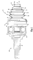
- FIG. 2 is a front cross-sectional view of a universal device including the boot shown in FIG. 1 .
- a universal joint 38 includes an outer joint member 40 having first shaft portion 42 and a chamber portion 44 .
- a plurality of inwardly facing grooves 46 , 48 are defined in the chamber portion 44 .
- the universal joint 38 also includes an inner joint member 50 having a second shaft portion 52 and a groove portion 54 .
- a plurality of outwardly facing grooves 56 , 58 are defined on an radially outer surface of the groove portion 54 .
- the groove portion 54 is disposed in the chamber portion 44 .
- a plurality of balls 60 , 62 are individually disposed in the plurality of inwardly facing grooves 46 , 48 and in the plurality of outwardly facing grooves 56 , 58 .
- the balls 60 , 62 transmit rotation between the outer joint member 40 and the inner joint member 50 . Only two balls 60 , 62 are shown in the drawings; however, most universal joints include six or eight balls.
- the inner joint member 50 and the outer joint member 40 are pivotable relative to one another during operation of the universal joint 38 .
- the exemplary universal joint 38 is an Auktor style joint.
- the inner joint member 50 and the outer joint member 40 are pivtoable relative to one another over a first range 64 of movement corresponding to normal operation.
- the inner joint member 50 and the outer joint member 40 can become disengaged from one another in response pivoting movement beyond the first range 64 .
- the inner joint member 50 and the outer joint member 40 can become disassembled with respect to one another due to over-angulation.
- a boot 10 for the universal joint 38 can prevent debris from entering the chamber portion 44 .
- the boot 10 includes a first sleeve portion 12 defining a first circular opening 14 .
- the first sleeve portion 12 encircles the chamber portion 44 .
- a clamp (not shown) can be used to substantially fix the first sleeve portion 12 to a radially outward facing surface of the chamber portion 44 .
- the boot 10 also includes a second sleeve portion 16 spaced from the first sleeve portion 12 along a boot axis 18 .
- the second sleeve portion 16 defines a second circular opening 20 having a smaller diameter than the first circular opening 14 .
- the second sleeve portion 16 encircles the second shaft portion 52 at a position spaced from the groove portion 54 .
- the boot 10 also includes a plurality of convolutions defined along the boot axis 18 between the first sleeve portion 12 and the second sleeve portion 16 .
- Each convolution is defined by a plurality of roots 22 , 24 , 26 , 28 extending radially inward toward the boot axis 18 and by a plurality of crests 30 , 32 , 34 , 36 extending radially outward away from the boot axis 18 .
- the boot 10 can have any number of convolutions.
- the first sleeve portion 12 , the second sleeve portion 16 , and the plurality of convolutes are integrally formed with respect one another.
- the plurality of roots 22 , 24 , 26 , 28 includes a first root 22 and a second root 24 immediately adjacent to one another.
- the first root 22 is closer to the first sleeve portion 12 than the second root 24 .
- the first root 22 extends radially toward the boot axis 18 further than the second root 24 .
- the first root 22 resists pivoting movement of the inner joint member 50 relative to the outer joint member 40 .
- This can be advantageous during assembly and transport of the universal joint 38 .
- the first root 22 can reduce the likelihood that the inner joint member 50 and the outer joint member 40 will become disassembled with respect to one another to over-angulation during assembly of the universal joint 38 to an operating environment such as a vehicle and/or during packaging, transport, and removal from packaging.
- the exemplary first root 22 will not prevent the inner joint member 50 and the outer joint member 40 from pivoting with respect to one another over the first range 64 .
- the first root 22 is immediately adjacent to the first sleeve portion 12 .
- the first root 22 is closest to the first sleeve portion 12 of the plurality of roots 22 , 24 , 26 , 28 .
- the first root 22 the root that limits pivoting movement, can be spaced from the first sleeve portion 12 by one or more convolutes, roots or crests.
- the first root 22 is thicker than the second root 24 .
- the exemplary first root 22 is thicker than all of other of the plurality of roots 22 , 24 , 26 , 28 .
- the first root 22 the root that limits pivoting movement, can be thinner than one or more of the other roots.
- the first root 22 extends radially further toward the boot axis 18 any of the other roots, including the third root 26 and the fourth root 28 .
- This arrangement can be desirable to reduce the likelihood that the second shaft portion 52 will abrasively contact the roots 24 , 26 , 28 .
- roots other than the first root 22 could extend the same distance toward the boot axis 18 .
- the first root 22 could have the same diameter as another root.
Abstract
Description
Claims (4)
Priority Applications (7)
| Application Number | Priority Date | Filing Date | Title |
|---|---|---|---|
| US11/330,762 US7468000B2 (en) | 2006-01-12 | 2006-01-12 | Boot for universal joint |
| KR1020060131451A KR20070075265A (en) | 2006-01-12 | 2006-12-21 | Boot for universal joint |
| DE602006021128T DE602006021128D1 (en) | 2006-01-12 | 2006-12-22 | Sleeve for universal joint |
| EP06077302A EP1808611B1 (en) | 2006-01-12 | 2006-12-22 | Boot for universal joint |
| AT06077302T ATE504752T1 (en) | 2006-01-12 | 2006-12-22 | SLEEVE FOR UNIVERSAL JOINT |
| CN2007100023215A CN101000074B (en) | 2006-01-12 | 2007-01-11 | Boot for universal joint |
| US12/258,039 US8112866B2 (en) | 2006-01-12 | 2008-10-24 | Method for resisting pivoting movement between an outer member and an inner member of a universal joint |
Applications Claiming Priority (1)
| Application Number | Priority Date | Filing Date | Title |
|---|---|---|---|
| US11/330,762 US7468000B2 (en) | 2006-01-12 | 2006-01-12 | Boot for universal joint |
Related Child Applications (1)
| Application Number | Title | Priority Date | Filing Date |
|---|---|---|---|
| US12/258,039 Division US8112866B2 (en) | 2006-01-12 | 2008-10-24 | Method for resisting pivoting movement between an outer member and an inner member of a universal joint |
Publications (2)
| Publication Number | Publication Date |
|---|---|
| US20070161429A1 US20070161429A1 (en) | 2007-07-12 |
| US7468000B2 true US7468000B2 (en) | 2008-12-23 |
Family
ID=37913846
Family Applications (2)
| Application Number | Title | Priority Date | Filing Date |
|---|---|---|---|
| US11/330,762 Expired - Fee Related US7468000B2 (en) | 2006-01-12 | 2006-01-12 | Boot for universal joint |
| US12/258,039 Expired - Fee Related US8112866B2 (en) | 2006-01-12 | 2008-10-24 | Method for resisting pivoting movement between an outer member and an inner member of a universal joint |
Family Applications After (1)
| Application Number | Title | Priority Date | Filing Date |
|---|---|---|---|
| US12/258,039 Expired - Fee Related US8112866B2 (en) | 2006-01-12 | 2008-10-24 | Method for resisting pivoting movement between an outer member and an inner member of a universal joint |
Country Status (6)
| Country | Link |
|---|---|
| US (2) | US7468000B2 (en) |
| EP (1) | EP1808611B1 (en) |
| KR (1) | KR20070075265A (en) |
| CN (1) | CN101000074B (en) |
| AT (1) | ATE504752T1 (en) |
| DE (1) | DE602006021128D1 (en) |
Families Citing this family (4)
| Publication number | Priority date | Publication date | Assignee | Title |
|---|---|---|---|---|
| WO2008058559A1 (en) * | 2006-11-16 | 2008-05-22 | Gkn Driveline International Gmbh | Expanding bellows for sealing an annular gap |
| DE102010009845A1 (en) * | 2009-03-02 | 2010-11-18 | GM Global Technology Operations, Inc., Detroit | Constant velocity joint |
| US9283842B2 (en) | 2012-11-29 | 2016-03-15 | U-Haul International, Inc. | Method and apparatus for drive shaft extension |
| US11209104B2 (en) | 2016-03-02 | 2021-12-28 | Carrier Corporation | Fastening system for a pipe passing through a panel of an air handling unit, and air handling unit comprising such a system |
Citations (19)
| Publication number | Priority date | Publication date | Assignee | Title |
|---|---|---|---|---|
| US4196598A (en) * | 1977-07-01 | 1980-04-08 | Honda Giken Kogyo Kabushiki Kaisha | Apparatus for prevention of the removal of a universal joint |
| US4278262A (en) | 1978-08-25 | 1981-07-14 | Toyota Jidosha Kogyo Kabushiki Kaisha | Rubber boot for use in universal joint |
| US4559025A (en) | 1983-04-15 | 1985-12-17 | Automobiles Citroen | Universal joint with bellows seal and vent |
| US4820238A (en) * | 1987-02-27 | 1989-04-11 | Keeper Co., Ltd. | Universal joint having a flexible boot |
| US5451186A (en) * | 1990-12-28 | 1995-09-19 | Gkn Glaenzer Spicer | Axially fixed transmission joint |
| US5599029A (en) | 1994-10-13 | 1997-02-04 | Nok Corporation | Boot having inwardly curved flanks |
| US5645286A (en) | 1993-09-30 | 1997-07-08 | Ntn Corporation | Resin boot for constant velocity universal joints |
| US5725432A (en) * | 1995-09-23 | 1998-03-10 | Gkn Automotive Ag | Constant velocity universal ball joints with window surfaces and ball surfaces having a desired roughness |
| US5765837A (en) | 1996-01-13 | 1998-06-16 | Lohr & Bromkamp Gmbh | Convoluted boot with inner annual ribs |
| US5879238A (en) | 1994-11-10 | 1999-03-09 | Draftex Industries Limited | Protective bellows |
| US6139027A (en) | 1998-01-05 | 2000-10-31 | Biekx; Ron O. | CV joint boot with sealing sleeves |
| US6179717B1 (en) | 1998-02-17 | 2001-01-30 | Gkn Lobro Gmbh | Driveshafts having convoluted boot seals with ventilation for joint interior |
| US6209885B1 (en) | 1998-04-23 | 2001-04-03 | Nok Corporation | Boot for universal joint |
| US6406375B1 (en) | 1999-11-05 | 2002-06-18 | Gkn Walterscheid Gmbh | Protective device for a drive assembly with a double universal joint |
| US6478309B1 (en) | 1999-08-26 | 2002-11-12 | Toyoda Gosei Co., Ltd. | Constant velocity joint boot |
| US20030171154A1 (en) | 2002-03-08 | 2003-09-11 | Gkn Automotive, Inc. | Propeller shaft assembly |
| US20040017046A1 (en) | 2001-01-05 | 2004-01-29 | Frazer Richard D. | Transmission joint boot |
| DE10323071A1 (en) | 2003-05-22 | 2004-12-09 | Daimlerchrysler Ag | Bellows, e.g. for sealing of steering shafts of motor vehicles, has several foldings between two fastening collars, also has different geometrical shapes and/or material properties along its length and periphery |
| US6938902B2 (en) | 2003-02-26 | 2005-09-06 | Delphi Technologies, Inc. | Boot with O-ring seal |
Family Cites Families (3)
| Publication number | Priority date | Publication date | Assignee | Title |
|---|---|---|---|---|
| US416598A (en) * | 1889-12-03 | Hydraulic-cylinder lubricator | ||
| US5201107A (en) * | 1990-08-29 | 1993-04-13 | Pmx Inc. | Method of assembling a constant velocity universal joint |
| DE10130859B4 (en) * | 2001-06-28 | 2009-09-17 | Gkn Driveline International Gmbh | Ball constant velocity fixed joint with multipart joint outer part |
-
2006
- 2006-01-12 US US11/330,762 patent/US7468000B2/en not_active Expired - Fee Related
- 2006-12-21 KR KR1020060131451A patent/KR20070075265A/en not_active Application Discontinuation
- 2006-12-22 DE DE602006021128T patent/DE602006021128D1/en active Active
- 2006-12-22 EP EP06077302A patent/EP1808611B1/en not_active Not-in-force
- 2006-12-22 AT AT06077302T patent/ATE504752T1/en not_active IP Right Cessation
-
2007
- 2007-01-11 CN CN2007100023215A patent/CN101000074B/en not_active Expired - Fee Related
-
2008
- 2008-10-24 US US12/258,039 patent/US8112866B2/en not_active Expired - Fee Related
Patent Citations (19)
| Publication number | Priority date | Publication date | Assignee | Title |
|---|---|---|---|---|
| US4196598A (en) * | 1977-07-01 | 1980-04-08 | Honda Giken Kogyo Kabushiki Kaisha | Apparatus for prevention of the removal of a universal joint |
| US4278262A (en) | 1978-08-25 | 1981-07-14 | Toyota Jidosha Kogyo Kabushiki Kaisha | Rubber boot for use in universal joint |
| US4559025A (en) | 1983-04-15 | 1985-12-17 | Automobiles Citroen | Universal joint with bellows seal and vent |
| US4820238A (en) * | 1987-02-27 | 1989-04-11 | Keeper Co., Ltd. | Universal joint having a flexible boot |
| US5451186A (en) * | 1990-12-28 | 1995-09-19 | Gkn Glaenzer Spicer | Axially fixed transmission joint |
| US5645286A (en) | 1993-09-30 | 1997-07-08 | Ntn Corporation | Resin boot for constant velocity universal joints |
| US5599029A (en) | 1994-10-13 | 1997-02-04 | Nok Corporation | Boot having inwardly curved flanks |
| US5879238A (en) | 1994-11-10 | 1999-03-09 | Draftex Industries Limited | Protective bellows |
| US5725432A (en) * | 1995-09-23 | 1998-03-10 | Gkn Automotive Ag | Constant velocity universal ball joints with window surfaces and ball surfaces having a desired roughness |
| US5765837A (en) | 1996-01-13 | 1998-06-16 | Lohr & Bromkamp Gmbh | Convoluted boot with inner annual ribs |
| US6139027A (en) | 1998-01-05 | 2000-10-31 | Biekx; Ron O. | CV joint boot with sealing sleeves |
| US6179717B1 (en) | 1998-02-17 | 2001-01-30 | Gkn Lobro Gmbh | Driveshafts having convoluted boot seals with ventilation for joint interior |
| US6209885B1 (en) | 1998-04-23 | 2001-04-03 | Nok Corporation | Boot for universal joint |
| US6478309B1 (en) | 1999-08-26 | 2002-11-12 | Toyoda Gosei Co., Ltd. | Constant velocity joint boot |
| US6406375B1 (en) | 1999-11-05 | 2002-06-18 | Gkn Walterscheid Gmbh | Protective device for a drive assembly with a double universal joint |
| US20040017046A1 (en) | 2001-01-05 | 2004-01-29 | Frazer Richard D. | Transmission joint boot |
| US20030171154A1 (en) | 2002-03-08 | 2003-09-11 | Gkn Automotive, Inc. | Propeller shaft assembly |
| US6938902B2 (en) | 2003-02-26 | 2005-09-06 | Delphi Technologies, Inc. | Boot with O-ring seal |
| DE10323071A1 (en) | 2003-05-22 | 2004-12-09 | Daimlerchrysler Ag | Bellows, e.g. for sealing of steering shafts of motor vehicles, has several foldings between two fastening collars, also has different geometrical shapes and/or material properties along its length and periphery |
Also Published As
| Publication number | Publication date |
|---|---|
| DE602006021128D1 (en) | 2011-05-19 |
| US20090048029A1 (en) | 2009-02-19 |
| US8112866B2 (en) | 2012-02-14 |
| EP1808611A1 (en) | 2007-07-18 |
| EP1808611B1 (en) | 2011-04-06 |
| KR20070075265A (en) | 2007-07-18 |
| US20070161429A1 (en) | 2007-07-12 |
| CN101000074A (en) | 2007-07-18 |
| CN101000074B (en) | 2012-10-10 |
| ATE504752T1 (en) | 2011-04-15 |
Similar Documents
| Publication | Publication Date | Title |
|---|---|---|
| US7507161B2 (en) | Propshaft with constant velocity joint attachment | |
| US7468000B2 (en) | Boot for universal joint | |
| US8328650B2 (en) | Constant velocity universal joint | |
| EP2177779B1 (en) | Silicone boot for constant velocity universal joint and constant velocity universal joint | |
| WO2016136355A1 (en) | Constant velocity universal joint | |
| US8348774B2 (en) | Constant velocity joint and constant velocity joint boot | |
| JP2007211927A (en) | Boots for constant velocity universal joint | |
| JP2012237333A (en) | Boot band | |
| US7993227B2 (en) | Hub for power transmission apparatus | |
| JP4562592B2 (en) | boots | |
| WO2007072620A1 (en) | Constant velocity universal joint | |
| JP7020366B2 (en) | Universal joint | |
| JP2001165188A (en) | Constant velocity joint boot | |
| JP2008045696A (en) | Boots fixing structure | |
| JP2007146959A (en) | Sealing structure | |
| JP2007146932A (en) | Boot for uniform speed universal joint | |
| JP2009275758A (en) | Constant velocity universal joint boot | |
| JP2008045675A (en) | Boot mounting structure of constant velocity universal joint | |
| JP2004108591A (en) | Resin boot for constant velocity joint | |
| JP2019138463A (en) | Boot band | |
| JP2008025742A (en) | Mounting structure for constant velocity universal joint boot | |
| JP2007239879A (en) | Mounting structure of boot for constant velocity universal joint | |
| JP2020051542A (en) | Drive shaft | |
| JP2005053286A (en) | Fixed type uniform motion universal joint for steering | |
| JP2016180460A (en) | Constant velocity universal joint |
Legal Events
| Date | Code | Title | Description |
|---|---|---|---|
| AS | Assignment |
Owner name: DELPHI TECHNOLOGIES, INC., MICHIGAN Free format text: ASSIGNMENT OF ASSIGNORS INTEREST;ASSIGNOR:VILLALOBOS, FEDERICO;REEL/FRAME:017475/0514 Effective date: 20060109 |
|
| STCF | Information on status: patent grant |
Free format text: PATENTED CASE |
|
| AS | Assignment |
Owner name: GM GLOBAL TECHNOLOGY OPERATIONS, INC., MICHIGAN Free format text: ASSIGNMENT OF ASSIGNORS INTEREST;ASSIGNOR:DELPHI TECHNOLOGIES, INC.;REEL/FRAME:023449/0065 Effective date: 20091002 Owner name: GM GLOBAL TECHNOLOGY OPERATIONS, INC.,MICHIGAN Free format text: ASSIGNMENT OF ASSIGNORS INTEREST;ASSIGNOR:DELPHI TECHNOLOGIES, INC.;REEL/FRAME:023449/0065 Effective date: 20091002 |
|
| AS | Assignment |
Owner name: GM GLOBAL TECHNOLOGY OPERATIONS, INC.,MICHIGAN Free format text: ASSIGNMENT OF ASSIGNORS INTEREST;ASSIGNOR:DELPHI TECHNOLOGIES, INC.;REEL/FRAME:023988/0754 Effective date: 20091002 Owner name: UNITED STATES DEPARTMENT OF THE TREASURY,DISTRICT Free format text: SECURITY AGREEMENT;ASSIGNOR:GM GLOBAL TECHNOLOGY OPERATIONS, INC.;REEL/FRAME:023990/0349 Effective date: 20090710 Owner name: UAW RETIREE MEDICAL BENEFITS TRUST,MICHIGAN Free format text: SECURITY AGREEMENT;ASSIGNOR:GM GLOBAL TECHNOLOGY OPERATIONS, INC.;REEL/FRAME:023990/0831 Effective date: 20090710 Owner name: GM GLOBAL TECHNOLOGY OPERATIONS, INC., MICHIGAN Free format text: ASSIGNMENT OF ASSIGNORS INTEREST;ASSIGNOR:DELPHI TECHNOLOGIES, INC.;REEL/FRAME:023988/0754 Effective date: 20091002 Owner name: UNITED STATES DEPARTMENT OF THE TREASURY, DISTRICT Free format text: SECURITY AGREEMENT;ASSIGNOR:GM GLOBAL TECHNOLOGY OPERATIONS, INC.;REEL/FRAME:023990/0349 Effective date: 20090710 Owner name: UAW RETIREE MEDICAL BENEFITS TRUST, MICHIGAN Free format text: SECURITY AGREEMENT;ASSIGNOR:GM GLOBAL TECHNOLOGY OPERATIONS, INC.;REEL/FRAME:023990/0831 Effective date: 20090710 |
|
| AS | Assignment |
Owner name: GM GLOBAL TECHNOLOGY OPERATIONS, INC., MICHIGAN Free format text: RELEASE BY SECURED PARTY;ASSIGNOR:UNITED STATES DEPARTMENT OF THE TREASURY;REEL/FRAME:025386/0591 Effective date: 20100420 Owner name: GM GLOBAL TECHNOLOGY OPERATIONS, INC., MICHIGAN Free format text: RELEASE BY SECURED PARTY;ASSIGNOR:UAW RETIREE MEDICAL BENEFITS TRUST;REEL/FRAME:025386/0503 Effective date: 20101026 |
|
| AS | Assignment |
Owner name: GM GLOBAL TECHNOLOGY OPERATIONS, INC., MICHIGAN Free format text: ASSIGNMENT OF ASSIGNORS INTEREST;ASSIGNOR:GM GLOBAL TECHNOLOGY OPERATIONS, INC.;REEL/FRAME:027842/0918 Effective date: 20101130 Owner name: PACIFIC CENTURY MOTORS, INC., CHINA Free format text: ASSIGNMENT OF ASSIGNORS INTEREST;ASSIGNOR:GM GLOBAL TECHNOLOGY OPERATIONS, INC.;REEL/FRAME:027842/0918 Effective date: 20101130 |
|
| AS | Assignment |
Owner name: STEERING SOLUTIONS IP HOLDING CORPORATION, MICHIGA Free format text: ASSIGNMENT OF ASSIGNORS INTEREST;ASSIGNORS:PACIFIC CENTURY MOTORS, INC.;NEXTEER (BEIJING) TECHNOLOGY CO., LTD.;REEL/FRAME:027870/0666 Effective date: 20120126 |
|
| FPAY | Fee payment |
Year of fee payment: 4 |
|
| FPAY | Fee payment |
Year of fee payment: 8 |
|
| FEPP | Fee payment procedure |
Free format text: MAINTENANCE FEE REMINDER MAILED (ORIGINAL EVENT CODE: REM.); ENTITY STATUS OF PATENT OWNER: LARGE ENTITY |
|
| LAPS | Lapse for failure to pay maintenance fees |
Free format text: PATENT EXPIRED FOR FAILURE TO PAY MAINTENANCE FEES (ORIGINAL EVENT CODE: EXP.); ENTITY STATUS OF PATENT OWNER: LARGE ENTITY |
|
| STCH | Information on status: patent discontinuation |
Free format text: PATENT EXPIRED DUE TO NONPAYMENT OF MAINTENANCE FEES UNDER 37 CFR 1.362 |
|
| FP | Lapsed due to failure to pay maintenance fee |
Effective date: 20201223 |