US7464686B2 - Leak fuel collection apparatus of internal combustion engine - Google Patents
Leak fuel collection apparatus of internal combustion engine Download PDFInfo
- Publication number
- US7464686B2 US7464686B2 US10/535,852 US53585203A US7464686B2 US 7464686 B2 US7464686 B2 US 7464686B2 US 53585203 A US53585203 A US 53585203A US 7464686 B2 US7464686 B2 US 7464686B2
- Authority
- US
- United States
- Prior art keywords
- leak
- engine
- fuel
- predetermined value
- pipe
- Prior art date
- Legal status (The legal status is an assumption and is not a legal conclusion. Google has not performed a legal analysis and makes no representation as to the accuracy of the status listed.)
- Expired - Fee Related, expires
Links
- 239000000446 fuel Substances 0.000 title claims abstract description 154
- 238000002485 combustion reaction Methods 0.000 title claims abstract description 36
- 238000002347 injection Methods 0.000 claims description 37
- 239000007924 injection Substances 0.000 claims description 37
- 239000003921 oil Substances 0.000 description 49
- LCGLNKUTAGEVQW-UHFFFAOYSA-N Dimethyl ether Chemical compound COC LCGLNKUTAGEVQW-UHFFFAOYSA-N 0.000 description 12
- 239000000203 mixture Substances 0.000 description 11
- 239000003915 liquefied petroleum gas Substances 0.000 description 8
- 238000009835 boiling Methods 0.000 description 5
- 239000007788 liquid Substances 0.000 description 4
- 230000006866 deterioration Effects 0.000 description 3
- 239000004215 Carbon black (E152) Substances 0.000 description 2
- UGFAIRIUMAVXCW-UHFFFAOYSA-N Carbon monoxide Chemical compound [O+]#[C-] UGFAIRIUMAVXCW-UHFFFAOYSA-N 0.000 description 2
- 229910002091 carbon monoxide Inorganic materials 0.000 description 2
- 239000000295 fuel oil Substances 0.000 description 2
- 229930195733 hydrocarbon Natural products 0.000 description 2
- 150000002430 hydrocarbons Chemical class 0.000 description 2
- 239000000470 constituent Substances 0.000 description 1
- 230000036461 convulsion Effects 0.000 description 1
- 230000003247 decreasing effect Effects 0.000 description 1
- 238000010586 diagram Methods 0.000 description 1
- 239000002828 fuel tank Substances 0.000 description 1
- 239000000463 material Substances 0.000 description 1
Images


Classifications
-
- F—MECHANICAL ENGINEERING; LIGHTING; HEATING; WEAPONS; BLASTING
- F02—COMBUSTION ENGINES; HOT-GAS OR COMBUSTION-PRODUCT ENGINE PLANTS
- F02M—SUPPLYING COMBUSTION ENGINES IN GENERAL WITH COMBUSTIBLE MIXTURES OR CONSTITUENTS THEREOF
- F02M55/00—Fuel-injection apparatus characterised by their fuel conduits or their venting means; Arrangements of conduits between fuel tank and pump F02M37/00
- F02M55/002—Arrangement of leakage or drain conduits in or from injectors
Definitions
- the present invention relates to an apparatus for collecting the fuel leaked from the fuel injection system of an internal combustion engine through clearances such as a the circumferential clearance of the needle valve, etc. of the fuel injection nozzle for injecting fuel into the cylinder to a leak oil collection pipe through the leak passage in said fuel injection nozzle.
- the apparatus is particularly applied to an internal combustion engine using low boiling point fuel such as DME(dimethyl ether), LPG(liquefied petroleum gas), etc.
- a diesel engine having a cylinder into which low boiling point fuel such as DME(dimethyl ether), LPG(liquefied petroleum gas), etc. pressurized into a liquid state, is injected from the injection nozzle the fuel is pressurized in the fuel supply system for supplying the fuel to the injection nozzle and in the fuel injection system, because the fuel must be injected into the cylinder in a liquid state.
- low boiling point fuel such as DME(dimethyl ether), LPG(liquefied petroleum gas), etc.
- the amount of leaked fuel leaked to the upper part of the fuel injection nozzle through clearances such as the circumferential clearance of the needle valve, etc. in a pressurized liquid state of low viscosity increases, so the leaked fuel is collected to be supplied for combustion, because if the leaked fuel is released into the atmosphere the thermal efficiency of the engine reduces.
- the fuel leaked from the injection nozzle is collected to the fuel supply system to be reused as disclosed in Japanese Laid-Open patent Application No. 9-112732.
- the combustion environment in the cylinder is such that the incomplete combustion of the lean mixture containing the leak fuel is liable to occur, and fuel consumption increases due to the incomplete combustion of the leaked fuel and at the same time the deterioration in exhaust emission is induced due to the generation of harmful matter such as CO(carbon monoxide) and HC(hydro carbon).
- the object of the present invention is, in light of the problems of prior art, to provide an leak fuel collection apparatus of an internal combustion engine, by which apparatus fuel consumption and exhaust emission can be improved by retaining the combustion condition of the lean mixture of the fresh air and the fuel leaked from the injection nozzle in a good state all over the operation range of the engine particularly in an internal combustion engine using low boiling point fuel.
- the present invention provides to solve the problems mentioned above, and is directed to a system for collecting the fuel leaked from the fuel injection nozzle for injecting fuel into the cylinder of the engine through clearances such as the circumferential clearance of the needle valve, etc. of the injection nozzle through the leak passage in the injection nozzle to a leak oil collection pipe, wherein said leak oil collection pipe is connected to the intake air passage of the engine, and a leak pipe open/close valve for opening or closing the leak oil collection pipe line is provided to the leak oil collection pipe.
- the apparatus is constituted so that said leak pipe open/close valve is opened when the engine load at an engine rotation speed exceeds a predetermined value, and the same is closed when the engine load at said engine rotation speed is equal to or lower than said predetermined value.
- the apparatus is provided with:
- an engine load detector for detecting the load of the engine
- an engine rotation speed detector for detecting the rotation speed of the engine
- a controller which controls the leak pipe open/close valve, based on the detected value of the engine load inputted from the engine load detector and the detected value of the rotation speed inputted from the engine rotation speed detector, such that the leak pipe open/close valve is opened when the detected value of the engine load at an engine rotation speed exceeds a predetermined value, determined based on the rotation speed, and said leak pipe open/close valve is closed when the detected value of the engine load at said engine rotation speed is equal to or lower than said predetermined value.
- the apparatus is constituted so that said leak pipe open/close valve is opened when the pressure in the leak oil collection pipe exceeds a predetermined value and the same is closed when the pressure in the leak oil collection pipe is equal to or lower than said predetermined value.
- the apparatus is provided with:
- a leak pipe pressure detector for detecting the pressure in the leak oil collection pipe
- a controller which controls the leak pipe open/close valve, based on the detected value of the pressure inputted from the leak pipe pressure detector, such that the leak pipe open/close valve is opened when the detected value of the pressure in the leak oil collection pipe exceeds a predetermined value and said leak pipe open/close valve is closed when the detected value of the pressure in the leak oil collection pipe is equal to or lower than said predetermined value.
- the apparatus is constituted so that said leak pipe open/close valve is opened when the engine load at an engine rotation speed exceeds a predetermined value, determined based on the rotation speed, and at the same time the pressure in the leak oil collection pipe exceeds a predetermined value, and said leak pipe open/close valve is closed when the engine load at said engine rotation speed is equal to or lower than said predetermined value of engine load and at the same time the pressure in the leak oil collection pipe is equal to or lower than said predetermined value of pressure.
- the apparatus is provided with:
- an engine load detector for detecting the load of the engine
- an engine rotation speed detector for detecting the rotation speed of the engine
- a leak pipe pressure detector for detecting the pressure in the leak oil collection pipe
- a controller which controls the leak pipe open/close valve, based on the detected value of the engine load inputted from the engine load detector, the detected value of the rotation speed inputted from the engine rotation speed detector, and the detected value of the pressure inputted from the leak pipe pressure detector, such that the leak pipe open/close valve is opened when the engine load at an engine rotation speed exceeds a predetermined value, determined based on the rotation speed, and at the same time the pressure in the leak oil collection pipe exceeds a predetermined value or when the engine load at said engine rotation speed is equal to or lower than said predetermined value of load and at the same time the pressure in the leak oil collection pipe exceeds said predetermined value of pressure, and controls the leak pipe open/close valve, such that said leak pipe open/close valve is closed when the detected value of the engine load at said engine rotation speed is equal to or lower than said predetermined value of load and at the same time the detected value of the pressure in the leak oil collection pipe is equal to or lower than said predetermined value of pressure.
- the fuel leaked from the injection nozzle is introduced to the intake air passage via a leak oil collection pipe line, a leak pipe open/close valve is controlled to open or close the leak pipe, and the valve is opened when the engine is operated in a high load range to introduce the leaked fuel into the intake air passage to be mixed with the intake air and supplied to the cylinder of the engine, whereby the leaked fuel can be burned well in the cylinder without unburned fuel remained.
- a denser fuel/air pre-mixture can be supplied to the cylinder as intake air of the engine and good combustion with lesser fuel remained unburned can be realized.
- the valve to introduce the leaked fuel into the intake air passage of the engine when the engine is operating in the range of high load, the leaked fuel introduced into the cylinder in the state mixed with intake air can be burned well in the cylinder without unburned fuel remained, and by closing the valve in order to store the leaked fuel in the leak oil collection pipe until the pressure in the leak oil collection pipe reaches a certain value and opening the valve when the pressure reaches said certain value to introduce the leaked fuel increased in pressure in the leak oil collection pipe into the intake air passage to be mixed with intake air when the engine is operating in the range of low load, denser fuel/air mixture is supplied to the cylinder and good combustion with lesser fuel remained unburned can be realized even in the range of low load operation.
- the leak fuel can be burned in good combustion conditions in all load range of the engine.
- FIG. 1 is a plan view of an embodiment of the leak fuel collection apparatus of a diesel engine according to the present invention.
- FIG. 2 is a control block diagram of the leak fuel collection apparatus.
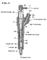
- FIG. 3 is a cross sectional view of the injection nozzle in the leak fuel collection apparatus.
- FIG. 4A and FIG. 4B are illustrations for explaining the operation of the leak pipe valve responding to engine load.
- FIG. 5A and FIG. 5B are illustrations for explaining the operation of the leak pipe valve responding to the pressure in the leak pipe.
- FIG. 6 is an illustration for explaining the operation of the leak pipe valve responding to engine load and the pressure in the leak pipe.
- FIG. 7 is a graph showing fuel consumption, HC emission, and CO emission vs. engine load respectively in (A), (B),and (C) when the collection of leaked fuel is done and not done.
- reference numeral 100 is an engine (diesel engine)
- 2 's are fuel injection nozzles (detailed later) mounted to each of the cylinders of the engine 100
- 1 is a fuel injection pump which compresses fuel to send it to each injection nozzle 2 by way of each fuel injection pipe 3
- 4 is a fuel supply pipe for supplying fuel to the fuel injection pump 1 from a fuel tank not shown in the drawing by means of a fuel supply pump not shown in the drawing.
- Reference numeral 7 is the intake manifold of the engine 100 , and 6 is the intake air pipe connecting with the intake manifold 7 .
- DME dimethyl ether
- LPG liquefied petroleum gas
- the present invention can be applied also in the case light oil or heavy oil is used as fuel.
- the structure of said fuel injection pump 1 is the same as that of a conventional in-line, jerk fuel injection pump and detailed explanation thereof is omitted.
- Reference numeral 5 is a leak oil collection pipe (leak pipe line) connecting the leak fuel passage 28 and leak fuel connector 29 of the injection nozzle 2 shown in FIG. 3 to said intake air pipe 6 .
- Reference numeral 8 is a leak pipe valve attached to the leak oil collection pipe 5 for opening or closing the passage in the leak oil collection pipe line, the valve being composed of an electromagnetic valve capable of controlling flow rate.
- Reference numeral 10 is a leak pipe pressure detector for detecting the pressure in the leak oil collection pipe 5
- 11 is an engine load detector for detecting the load (engine output) of the engine 100
- 12 is engine rotation speed detector for detecting the rotation speed of the engine 100
- 9 is a controller, of which is detailed later, and to which is inputted the pressure in the leak oil collection pipe 5 detected by the leak pipe pressure detector 10 ; the engine load detected by the engine load detector 11 , and the engine rotation speed detected by the engine rotation speed detector 12 .
- the control signal of said controller 9 is sent to the leak pipe open/close valve 8 via a control line 9 a.
- reference numeral 21 is a nozzle body
- 24 is a nozzle chip attached to the nozzle body 21 at its end by means of a nozzle nut 30 screwed in to the nozzle body 21
- 25 is one of a plurality of nozzle holes drilled in the end part of the nozzle chip 24
- Reference numeral 26 is an annular shaped fuel pool formed in the nozzle chip 24
- each of 29 a , 29 b , 29 c is a fuel passage provided in the nozzle body 21 and the nozzle chip 24
- Reference numeral 32 is a fuel intake connector with a filter 32 a accommodated therein, the connector being screwed into the nozzle body 21 at the upper part thereof.
- the fuel pressure-fed from the fuel injection pump 1 via the fuel injection pipe 3 is introduced to the fuel pool 26 by way of the fuel passage 29 a , 29 b , and 29 c.
- Reference numeral 23 is a needle valve received in the nozzle chip 24 for reciprocal sliding, the fuel pool 26 is communicated or disconnected to the injection holes 25 in accordance with the unseating or seating of the tip of the needle valve 23 onto the seat formed in the nozzle chip 24 .
- Reference numeral 27 is a needle valve spring accommodated in the needle valve spring room 27 a of the nozzle body 21 , 31 is a lower spring retainer provided between the top end of the needle valve 23 and the lower end face of the needle valve spring 27 , and 22 is an upper spring retainer for supporting the needle valve spring 27 at the upper end face thereof.
- the opening pressure of the needle valve 23 is determined by the spring force of the needle valve spring 27 .
- Reference numeral 28 is a leak fuel passage which passes through the center part of the upper spring retainer 22 to communicate the needle valve spring room 27 a with the leak fuel connector 29 .
- the detected value of the load(output) of the engine 100 detected by the engine load detector 11 is inputted to the load comparing section 92 of the controller 9 , and the detected value of the rotation speed of the engine 100 detected by the engine rotation speed detector 12 is inputted to the rotation speed comparing section 94 of the controller 9 .
- the detected value of the pressure in the leak oil collection pipe 5 detected by the leak pipe pressure detector 10 is inputted to the leak pressure comparing section 96 of the controller.
- Reference numeral 91 is a switchover load setting section, in which is set leak pipe valve switchover load L 0 which is the lower limit value of the engine load when the leaked fuel stored in the leak oil collection pipe 5 is supplied into the intake pipe 6 , the switchover load L 0 of opened leak pipe valve being related to the switchover rotation speed which is set in the switchover rotation speed setting section 93 of the controller 9 .
- the switchover load L 0 which is defined as a function of engine rotation speed as shown in FIG. 4A , is set in the switchover load setting section 91 and switchover rotation speed setting section 93 .
- the leak pipe valve 8 When the engine is operating in the high load range above the switchover load L 0 , the leak pipe valve 8 is opened, and when the engine is operating in the low load range below the switchover load L 0 , the leak pipe valve 8 is closed, the switchover load L 0 changing depending on the engine rotation speed.
- Reference numeral 95 is the switchover leak pressure setting section of the controller 9 in which is set leak pipe valve switchover pressure P 0 , above which pressure the leak pipe valve 8 is opened and the leak fuel stored in the leak oil collection pipe 5 is supplied to the intake air pipe 6 .
- the detected value of the engine load detected by the engine load detector 11 is compared with the leak pipe valve switchover load L 0 set in the switchover load setting section 91 , and in the rotation speed comparing section 94 , the detected value of the engine rotation speed detected by the engine rotation speed detector 12 is compared with the switchover rotation speed set in the switchover rotation speed setting section 93 , and these results of comparison are outputted to the operating condition/valve openings calculation section 97 of the controller 9 .
- the detected value of the pressure in the leak oil collection pipe detected by the leak pipe pressure detector 10 is compared with the leak pipe valve switchover pressure P 0 set in the switchover pressure setting section 95 , and the result of comparison is outputted to the leak pipe pressure related valve openings calculation section 98 of the controller 9 .
- the operating condition related valve openings calculation section 97 outputs a signal, based on the result of the comparison of the detected value of the engine load with the leak pipe valve switchover load L 0 in the load comparing section 92 and the result of the comparison of the detected engine rotation speed with the leak pipe open/close switchover rotation speed in the rotation speed comparing section 94 , to open the leak pipe valve 8 to the open/close valve control section 99 of the controller 9 when the detected engine load is higher than the leak pipe valve switchover load L 0 , that is, when the engine load is in the range of leak pipe valve open in FIG. 4A .
- the operating condition related valve openings calculation section 97 When the detected engine load is lower than the leak pipe valve switchover load L 0 , that is, when the pressure is in the range of leak pipe valve close in FIG. 4A , the operating condition related valve openings calculation section 97 outputs a signal, to the valve control section 99 to close the leak pipe valve 8 .
- the leak pressure related valve openings calculation section 98 outputs a signal, based on the result of the comparison of the detected value of the pressure in the leak oil collection pipe with the leak pipe valve switchover pressure P.sub. 0 in the leak pressure comparing section 96 , to open the leak pipe valve 8 to the valve control section 99 when the detected pressure in the leak oil collection pipe is higher than the leak pipe valve switchover pressure P 0 , that is, when the pressure is in the range of leak pipe valve open in FIG. 5A ,
- the leak pressure related valve openings calculation section 98 When the detected pressure in the leak oil collection pipe is lower than the leak pipe valve switchover pressure P 0 , that is, when the pressure is in the range of leak pipe valve close in FIG. 5A , the leak pressure related valve openings calculation section 98 outputs a signal to the valve control section 99 to close the leak pipe valve 8 .
- the output signal from the operating condition related valve openings calculation section 97 to open the leak pipe valve 8 is inputted to the valve control section 99 , and the valve control section 99 allows the leak pipe valve 8 to open irrespective of the result of the comparison of the detected value of the pressure in the leak oil collection pipe with the leak pipe valve switchover pressure P 0 .
- the output signal outputted from the operating condition related valve openings calculation section 97 to close the leak pipe valve 8 is inputted to the valve control section 99 , and the valve control section 99 allows the leak pipe valve 8 to close.
- the valve control section 99 allows the leak pipe valve 8 to open even if the detected engine load is lower than the leak pipe valve switchover load L 0 .
- the valve control section 99 allows the leak pipe valve 8 to close.
- FIG. 4B shows the open/close operation of the leak pipe valve 8 when only the engine load changes with time
- FIG. 5B shows the open/close operation of the leak pipe valve 8 when only the pressure in the leak pipe changes with time
- FIG. 6 shows the open/close operation of the leak pipe valve 8 when both the engine load and the pressure in the leak pipe change with time.
- FIG. 7 are shown respectively in (A), (B), and (C) fuel consumption, HC(hydrocarbon) emission, and CO(carbon monoxide) vs. engine load when the leaked fuel is returned to the intake pipe 6 (indicated with A) and when the leaked fuel is released to the outside (indicated with B).
- fuel consumption can be improved by returning the leaked fuel to the intake pipe 6 .
- HC and CO emission increase in the low engine load, but this increase in HC and CO emission can be suppressed to the minimum according to the present invention by closing the leak pipe valve 8 .
- the leaked fuel is introduced to the intake air pipe 6 to be mixed with the intake air to be supplied to the cylinder of the engine 100 and the leaked fuel introduced into the cylinder can be burned well in the cylinder without unburned fuel remained.
- the leak pipe valve 8 In the range of low load, the leak pipe valve 8 is closed until the pressure in the leak oil collection pipe 5 reaches the pressure of P 0 , and when the pressure in the leak oil collection pipe 5 exceeds the pressure of P 0 the leak pipe valve 8 is opened and the leaked fuel increased in pressure in the leak oil collection pipe 5 is introduced into the intake air in the intake air pipe 6 to be mixed with the intake air to produce dense mixture, which is supplied into the cylinder and good combustion with lesser fuel remained unburned can be realized even in a low load range of the engine operation.
- the leaked fuel can be burned in good combustion conditions in all load range of the engine operation.
- an open/close valve is provided in the leak pipe for collecting the leaked fuel, the valve is opened when the engine is operating in the range of high load to introduce the leaked fuel into the intake air passage of the engine, whereby the leaked fuel is mixed with the intake air in the intake air passage and supplied to the cylinder of the engine, and the leaked fuel introduced into the cylinder can be burned well in the cylinder without unburned fuel remained.
- the valve is closed to cut the supply of the leaked fuel to the intake passage, by which the increase in fuel consumption and the deterioration in exhaust emission can be evaded.
- the leak fuel introduced into the cylinder in the state mixed the with intake air can be burned well in the cylinder without unburned fuel remained by opening the valve to introduce the leak fuel into the intake air passage of the engine, and when the engine is operating in the range of low load, denser fuel/air mixture is supplied to the cylinder and good combustion with lesser fuel remained unburned can be realized even in the range of low load operation by closing the valve in order to store the leak fuel in the leak oil collection pipe until the pressure in the leak oil collection pipe reaches a certain value and opening the valve when the pressure reaches said certain value to introduce the leaked fuel increased in pressure in the leak oil collection pipe into the intake air passage to be mixed with intake air.
- the leaked fuel can be burned in good combustion conditions in all load range of the engine.
Landscapes
- Engineering & Computer Science (AREA)
- Chemical & Material Sciences (AREA)
- Combustion & Propulsion (AREA)
- Mechanical Engineering (AREA)
- General Engineering & Computer Science (AREA)
- Fuel-Injection Apparatus (AREA)
- Electrical Control Of Air Or Fuel Supplied To Internal-Combustion Engine (AREA)
- Combined Controls Of Internal Combustion Engines (AREA)
- Lubrication Details And Ventilation Of Internal Combustion Engines (AREA)
Abstract
A leak fuel collection apparatus of the internal combustion engine using leak oil collection pipe fuel is provided, by which the improvement in fuel consumption and exhaust emission can be achieved by improving the combustion condition of the leak fuel mixed with fresh air in the cylinder in correspondence with the engine operating conditions.
The leak oil collection pipe is connected to the intake air pipe of the engine, a leak pipe open/close valve is provided to the leak oil collection pipe for opening or closing the leak pipe, and the leak pipe open/close valve is opened when the engine load at an engine rotation speed exceeds a predetermined value determined for the rotation speed and is closed when the engine load at said rotation speed is equal to or lower than said predetermined value.
Description
1.Field of the Invention
The present invention relates to an apparatus for collecting the fuel leaked from the fuel injection system of an internal combustion engine through clearances such as a the circumferential clearance of the needle valve, etc. of the fuel injection nozzle for injecting fuel into the cylinder to a leak oil collection pipe through the leak passage in said fuel injection nozzle. The apparatus is particularly applied to an internal combustion engine using low boiling point fuel such as DME(dimethyl ether), LPG(liquefied petroleum gas), etc.
2. Description of the related Art
In a diesel engine having a cylinder into which low boiling point fuel such as DME(dimethyl ether), LPG(liquefied petroleum gas), etc. pressurized into a liquid state, is injected from the injection nozzle the fuel is pressurized in the fuel supply system for supplying the fuel to the injection nozzle and in the fuel injection system, because the fuel must be injected into the cylinder in a liquid state.
Therefore, in the fuel injection system of such a diesel engine, the amount of leaked fuel leaked to the upper part of the fuel injection nozzle through clearances such as the circumferential clearance of the needle valve, etc. in a pressurized liquid state of low viscosity increases, so the leaked fuel is collected to be supplied for combustion, because if the leaked fuel is released into the atmosphere the thermal efficiency of the engine reduces.
Generally, the fuel leaked from the injection nozzle is collected to the fuel supply system to be reused as disclosed in Japanese Laid-Open patent Application No. 9-112732.
However, in the case of a diesel engine using low boiling point fuel, it is conceivable, as the fuel is pressurized in the fuel supply system, to introduce the leaked fuel to the intake air supply passage to be vaporized thereby and supplied into the cylinder together with the fresh air (intake air of the engine) as an air-fuel mixture, instead of returning the leak fuel from the injection nozzle to fuel supply system as is in the case of a diesel engine using light oil or heavy oil as described in said Japanese Laid-Open patent Application No. 9-112732.
When the leaked fuel from the injection nozzle is introduced into the air supply passage to be mixed with the fresh air to be supplied as intake air of the engine, the mixture is extremely lean mixture of the leaked fuel and fresh air, and incomplete combustion with unburned fuel remained is prone to occur in the cylinder.
Particularly, in a low load range with decreased injection amount of fuel into the cylinder, the combustion environment in the cylinder is such that the incomplete combustion of the lean mixture containing the leak fuel is liable to occur, and fuel consumption increases due to the incomplete combustion of the leaked fuel and at the same time the deterioration in exhaust emission is induced due to the generation of harmful matter such as CO(carbon monoxide) and HC(hydro carbon).
The object of the present invention is, in light of the problems of prior art, to provide an leak fuel collection apparatus of an internal combustion engine, by which apparatus fuel consumption and exhaust emission can be improved by retaining the combustion condition of the lean mixture of the fresh air and the fuel leaked from the injection nozzle in a good state all over the operation range of the engine particularly in an internal combustion engine using low boiling point fuel.
The present invention provides to solve the problems mentioned above, and is directed to a system for collecting the fuel leaked from the fuel injection nozzle for injecting fuel into the cylinder of the engine through clearances such as the circumferential clearance of the needle valve, etc. of the injection nozzle through the leak passage in the injection nozzle to a leak oil collection pipe, wherein said leak oil collection pipe is connected to the intake air passage of the engine, and a leak pipe open/close valve for opening or closing the leak oil collection pipe line is provided to the leak oil collection pipe.
The apparatus is constituted so that said leak pipe open/close valve is opened when the engine load at an engine rotation speed exceeds a predetermined value, and the same is closed when the engine load at said engine rotation speed is equal to or lower than said predetermined value.
It is preferable that the apparatus is provided with:
an engine load detector for detecting the load of the engine,
an engine rotation speed detector for detecting the rotation speed of the engine, and
a controller which controls the leak pipe open/close valve, based on the detected value of the engine load inputted from the engine load detector and the detected value of the rotation speed inputted from the engine rotation speed detector, such that the leak pipe open/close valve is opened when the detected value of the engine load at an engine rotation speed exceeds a predetermined value, determined based on the rotation speed, and said leak pipe open/close valve is closed when the detected value of the engine load at said engine rotation speed is equal to or lower than said predetermined value.
It is suitable that the apparatus is constituted so that said leak pipe open/close valve is opened when the pressure in the leak oil collection pipe exceeds a predetermined value and the same is closed when the pressure in the leak oil collection pipe is equal to or lower than said predetermined value.
Preferably, the apparatus is provided with:
a leak pipe pressure detector for detecting the pressure in the leak oil collection pipe, and
a controller which controls the leak pipe open/close valve, based on the detected value of the pressure inputted from the leak pipe pressure detector, such that the leak pipe open/close valve is opened when the detected value of the pressure in the leak oil collection pipe exceeds a predetermined value and said leak pipe open/close valve is closed when the detected value of the pressure in the leak oil collection pipe is equal to or lower than said predetermined value.
Further, it is suitable that the apparatus is constituted so that said leak pipe open/close valve is opened when the engine load at an engine rotation speed exceeds a predetermined value, determined based on the rotation speed, and at the same time the pressure in the leak oil collection pipe exceeds a predetermined value, and said leak pipe open/close valve is closed when the engine load at said engine rotation speed is equal to or lower than said predetermined value of engine load and at the same time the pressure in the leak oil collection pipe is equal to or lower than said predetermined value of pressure.
Preferably, the apparatus is provided with:
an engine load detector for detecting the load of the engine,
an engine rotation speed detector for detecting the rotation speed of the engine,
a leak pipe pressure detector for detecting the pressure in the leak oil collection pipe, and
a controller which controls the leak pipe open/close valve, based on the detected value of the engine load inputted from the engine load detector, the detected value of the rotation speed inputted from the engine rotation speed detector, and the detected value of the pressure inputted from the leak pipe pressure detector, such that the leak pipe open/close valve is opened when the engine load at an engine rotation speed exceeds a predetermined value, determined based on the rotation speed, and at the same time the pressure in the leak oil collection pipe exceeds a predetermined value or when the engine load at said engine rotation speed is equal to or lower than said predetermined value of load and at the same time the pressure in the leak oil collection pipe exceeds said predetermined value of pressure, and controls the leak pipe open/close valve, such that said leak pipe open/close valve is closed when the detected value of the engine load at said engine rotation speed is equal to or lower than said predetermined value of load and at the same time the detected value of the pressure in the leak oil collection pipe is equal to or lower than said predetermined value of pressure.
As mentioned above, in a diesel engine having a cylinder into which the fuel having low boiling temperature such as DME(dimethyl ether), LPG(liquefied petroleum gas), etc. pressurized into a liquid state of low viscosity is injected from the injection nozzle into the cylinder is supplied to the injection nozzle, fuel leakage from the circumferential clearance of the needle valve, etc. of the injection nozzle toward the upper part of the injection pump increases.
However, according to the present invention, the fuel leaked from the injection nozzle is introduced to the intake air passage via a leak oil collection pipe line, a leak pipe open/close valve is controlled to open or close the leak pipe, and the valve is opened when the engine is operated in a high load range to introduce the leaked fuel into the intake air passage to be mixed with the intake air and supplied to the cylinder of the engine, whereby the leaked fuel can be burned well in the cylinder without unburned fuel remained.
On the other hand, when the engine is operated in a low load range, as the amount of the leak fuel is small and the pre-mixture thereof with the intake air is very lean, the complete combustion of the leak fuel is difficult. Therefore, by closing the leak pipe valve to stop the introduction of the leaked fuel into the intake air passage, the increase in fuel consumption and deterioration in exhaust emission can be evaded.
Further, by closing the leak pipe valve until the pressure in the leak oil collection pipe reaches a predetermined value in order to store the leaked fuel in the leak oil collection pipe and opening the valve when the pressure reaches said predetermined value to introduce the leaked fuel increased in pressure into the intake air passage, a denser fuel/air pre-mixture can be supplied to the cylinder as intake air of the engine and good combustion with lesser fuel remained unburned can be realized.
Therefore, by opening the valve to introduce the leaked fuel into the intake air passage of the engine when the engine is operating in the range of high load, the leaked fuel introduced into the cylinder in the state mixed with intake air can be burned well in the cylinder without unburned fuel remained, and by closing the valve in order to store the leaked fuel in the leak oil collection pipe until the pressure in the leak oil collection pipe reaches a certain value and opening the valve when the pressure reaches said certain value to introduce the leaked fuel increased in pressure in the leak oil collection pipe into the intake air passage to be mixed with intake air when the engine is operating in the range of low load, denser fuel/air mixture is supplied to the cylinder and good combustion with lesser fuel remained unburned can be realized even in the range of low load operation.
In this way, the leak fuel can be burned in good combustion conditions in all load range of the engine.
An embodiment of the present invention will now be described with reference to the accompanying drawings. It is intended, however, that unless particularly specified, dimensions, materials, relative positions and so forth of the constituent parts in the embodiments shall be interpreted as illustrative only not as limitative of the scope of the present invention.
Referring to FIG. 1 showing the overall configuration of the leak fuel collection apparatus of a diesel engine according to the present invention, reference numeral 100 is an engine (diesel engine), 2's are fuel injection nozzles (detailed later) mounted to each of the cylinders of the engine 100, 1 is a fuel injection pump which compresses fuel to send it to each injection nozzle 2 by way of each fuel injection pipe 3, and 4 is a fuel supply pipe for supplying fuel to the fuel injection pump 1 from a fuel tank not shown in the drawing by means of a fuel supply pump not shown in the drawing.
In the embodiment, DME(dimethyl ether), LPG(liquefied petroleum gas), etc. is used as fuel for the engine 100. The present invention can be applied also in the case light oil or heavy oil is used as fuel.
The structure of said fuel injection pump 1 is the same as that of a conventional in-line, jerk fuel injection pump and detailed explanation thereof is omitted.
Referring to FIG. 3 showing the detail of said injection nozzle 2, reference numeral 21 is a nozzle body, 24 is a nozzle chip attached to the nozzle body 21 at its end by means of a nozzle nut 30 screwed in to the nozzle body 21, and 25 is one of a plurality of nozzle holes drilled in the end part of the nozzle chip 24. Reference numeral 26 is an annular shaped fuel pool formed in the nozzle chip 24, each of 29 a, 29 b, 29 c is a fuel passage provided in the nozzle body 21 and the nozzle chip 24. Reference numeral 32 is a fuel intake connector with a filter 32 a accommodated therein, the connector being screwed into the nozzle body 21 at the upper part thereof. The fuel pressure-fed from the fuel injection pump 1 via the fuel injection pipe 3 is introduced to the fuel pool 26 by way of the fuel passage 29 a, 29 b, and 29 c.
Next, the operation of the leak fuel collection apparatus will be explained with reference to FIG. 2 .
The detected value of the load(output) of the engine 100 detected by the engine load detector 11 is inputted to the load comparing section 92 of the controller 9, and the detected value of the rotation speed of the engine 100 detected by the engine rotation speed detector 12 is inputted to the rotation speed comparing section 94 of the controller 9.
On the other hand, the detected value of the pressure in the leak oil collection pipe 5 detected by the leak pipe pressure detector 10 is inputted to the leak pressure comparing section 96 of the controller.
To be more specific, the switchover load L0, which is defined as a function of engine rotation speed as shown in FIG. 4A , is set in the switchover load setting section 91 and switchover rotation speed setting section 93. When the engine is operating in the high load range above the switchover load L0, the leak pipe valve 8 is opened, and when the engine is operating in the low load range below the switchover load L0, the leak pipe valve 8 is closed, the switchover load L0 changing depending on the engine rotation speed.
In the load comparing section 92, the detected value of the engine load detected by the engine load detector 11 is compared with the leak pipe valve switchover load L0 set in the switchover load setting section 91, and in the rotation speed comparing section 94, the detected value of the engine rotation speed detected by the engine rotation speed detector 12 is compared with the switchover rotation speed set in the switchover rotation speed setting section 93, and these results of comparison are outputted to the operating condition/valve openings calculation section 97 of the controller 9.
In the leak pressure comparing section 96, the detected value of the pressure in the leak oil collection pipe detected by the leak pipe pressure detector 10 is compared with the leak pipe valve switchover pressure P0 set in the switchover pressure setting section 95, and the result of comparison is outputted to the leak pipe pressure related valve openings calculation section 98 of the controller 9.
The operating condition related valve openings calculation section 97 outputs a signal, based on the result of the comparison of the detected value of the engine load with the leak pipe valve switchover load L0 in the load comparing section 92 and the result of the comparison of the detected engine rotation speed with the leak pipe open/close switchover rotation speed in the rotation speed comparing section 94, to open the leak pipe valve 8 to the open/close valve control section 99 of the controller 9 when the detected engine load is higher than the leak pipe valve switchover load L0, that is, when the engine load is in the range of leak pipe valve open in FIG. 4A .
When the detected engine load is lower than the leak pipe valve switchover load L0, that is, when the pressure is in the range of leak pipe valve close in FIG. 4A , the operating condition related valve openings calculation section 97 outputs a signal, to the valve control section 99 to close the leak pipe valve 8.
On the other hand, the leak pressure related valve openings calculation section 98 outputs a signal, based on the result of the comparison of the detected value of the pressure in the leak oil collection pipe with the leak pipe valve switchover pressure P.sub.0 in the leak pressure comparing section 96, to open the leak pipe valve 8 to the valve control section 99 when the detected pressure in the leak oil collection pipe is higher than the leak pipe valve switchover pressure P0, that is, when the pressure is in the range of leak pipe valve open in FIG. 5A ,
When the detected pressure in the leak oil collection pipe is lower than the leak pipe valve switchover pressure P0, that is, when the pressure is in the range of leak pipe valve close in FIG. 5A , the leak pressure related valve openings calculation section 98 outputs a signal to the valve control section 99 to close the leak pipe valve 8.
When the detected engine load is higher than the leak pipe valve changeover load L0 (when the detected load is in the range of valve open in FIG. 4A ), the output signal from the operating condition related valve openings calculation section 97 to open the leak pipe valve 8 is inputted to the valve control section 99, and the valve control section 99 allows the leak pipe valve 8 to open irrespective of the result of the comparison of the detected value of the pressure in the leak oil collection pipe with the leak pipe valve switchover pressure P0.
When the detected engine load is lower than the leak pipe valve changeover load L0 (when the detected load is in the range of valve close in FIG. 4A ), the output signal outputted from the operating condition related valve openings calculation section 97 to close the leak pipe valve 8 is inputted to the valve control section 99, and the valve control section 99 allows the leak pipe valve 8 to close.
When the detected pressure in the leak oil collection pipe is higher than the leak pipe valve changeover pressure P0 (when the detected load is in the range of valve open in FIG. 5A ) and the output signal from the leak pressure related valve openings calculation section 97 to open the leak pipe valve 8 is inputted to the valve control section 99, the valve control section 99 allows the leak pipe valve 8 to open even if the detected engine load is lower than the leak pipe valve switchover load L0.
When the detected pressure in the leak oil collection pipe is lower than the leak pipe valve changeover pressure P0 (when the detected pressure is in the range of valve close in FIG. 5A ), and the output signal outputted from the leak pressure related valve openings calculation section 98 to close the leak pipe valve 8 is inputted to the valve control section 99, the valve control section 99 allows the leak pipe valve 8 to close.
In FIG. 7 are shown respectively in (A), (B), and (C) fuel consumption, HC(hydrocarbon) emission, and CO(carbon monoxide) vs. engine load when the leaked fuel is returned to the intake pipe 6 (indicated with A) and when the leaked fuel is released to the outside (indicated with B).
As can be recognized from the graph of FIG. 7(A) , fuel consumption can be improved by returning the leaked fuel to the intake pipe 6. When the leaked fuel is returned to the intake air pipe 6, HC and CO emission increase in the low engine load, but this increase in HC and CO emission can be suppressed to the minimum according to the present invention by closing the leak pipe valve 8.
Therefore, according to the present invention, in the range of high load that exceeds the load of L0 determined in correspondence to engine speed, the leaked fuel is introduced to the intake air pipe 6 to be mixed with the intake air to be supplied to the cylinder of the engine 100 and the leaked fuel introduced into the cylinder can be burned well in the cylinder without unburned fuel remained.
In the range of low load, the leak pipe valve 8 is closed until the pressure in the leak oil collection pipe 5 reaches the pressure of P0, and when the pressure in the leak oil collection pipe 5 exceeds the pressure of P0 the leak pipe valve 8 is opened and the leaked fuel increased in pressure in the leak oil collection pipe 5 is introduced into the intake air in the intake air pipe 6 to be mixed with the intake air to produce dense mixture, which is supplied into the cylinder and good combustion with lesser fuel remained unburned can be realized even in a low load range of the engine operation.
Thus, the leaked fuel can be burned in good combustion conditions in all load range of the engine operation.
Also, you can set the open/close switchover point of the leak pipe open/close valve 8 to the predetermined point based on the engine load or the pressure in the leak pipe, instead of controlling the opening and closing of the valve 8 based on the detected value of the pressure in the leak oil collection pipe, the engine load and the engine rotation speed.
As has been described in the foregoing, according to the present invention, an open/close valve is provided in the leak pipe for collecting the leaked fuel, the valve is opened when the engine is operating in the range of high load to introduce the leaked fuel into the intake air passage of the engine, whereby the leaked fuel is mixed with the intake air in the intake air passage and supplied to the cylinder of the engine, and the leaked fuel introduced into the cylinder can be burned well in the cylinder without unburned fuel remained. When the engine operating in the rage of low load, the valve is closed to cut the supply of the leaked fuel to the intake passage, by which the increase in fuel consumption and the deterioration in exhaust emission can be evaded.
By closing the valve in order to store the leaked fuel in the leak oil collection pipe until the pressure in the leak oil collection pipe reaches a certain value and opening the valve when the pressure reaches said certain value to introduce the leaked fuel increased in pressure in the leak oil collection pipe into the intake air passage to be mixed with the intake air, denser fuel/air mixture is supplied to the cylinder and good combustion with lesser fuel remained unburned can be realized even in the range of low load operation.
Therefore, when the engine is operating in the range of high load, the leak fuel introduced into the cylinder in the state mixed the with intake air can be burned well in the cylinder without unburned fuel remained by opening the valve to introduce the leak fuel into the intake air passage of the engine, and when the engine is operating in the range of low load, denser fuel/air mixture is supplied to the cylinder and good combustion with lesser fuel remained unburned can be realized even in the range of low load operation by closing the valve in order to store the leak fuel in the leak oil collection pipe until the pressure in the leak oil collection pipe reaches a certain value and opening the valve when the pressure reaches said certain value to introduce the leaked fuel increased in pressure in the leak oil collection pipe into the intake air passage to be mixed with intake air.
In this way, the leaked fuel can be burned in good combustion conditions in all load range of the engine.
Claims (14)
1. A leak fuel collection apparatus of an internal combustion engine for collecting fuel leaked from a fuel injection valve for injecting fuel into a cylinder of the engine, comprising:
a leak fuel passage provided inside the fuel injection valve for collecting the leaked fuel;
a leak oil collection pipe extending between the leak fuel passage and an, intake air passage of the engine;
a leak pipe open/close valve for opening or closing the leak oil collection pipe line; and
a controller that controls the leak pipe open/close valve based on an operating condition of the engine.
2. The leak fuel collection apparatus of an internal combustion engine according to claim 1 , wherein said controller opens said leak pipe open/close valve when an actual engine load exceeds a predetermined value, and closes said leak pipe open/close valve when the actual engine load is equal to or lower than said predetermined value.
3. The leak fuel collection apparatus of an internal combustion engine according to claim 1 , further comprising:
an engine load detector for detecting an engine load; and
wherein said controller controls said leak pipe open/close valve based on the detected engine load, such that the leak pipe open/close valve is opened when the detected engine load exceeds a predetermined value, and said leak pipe open/close valve is closed when the detected value of the engine load is equal to or lower than said predetermined value.
4. The leak fuel collection apparatus of an internal combustion engine according to claim 1 , wherein said controller opens said leak pipe open/close valve when a pressure in the leak oil collection pipe exceeds a predetermined value and closes said leak pipe open/close valve when the pressure in the leak oil collection pipe is equal to or lower than said predetermined value.
5. The leak fuel collection apparatus of an internal combustion engine according to claim 1 , further comprising:
a leak pipe pressure detector for detecting an actual pressure in the leak oil collection pipe,
wherein said controller controls the leak pipe open/close valve based on the detected pressure, such that the leak pipe open/close valve is opened when the detected pressure exceeds a predetermined value and closes said leak pipe open/close valve when the detected pressure is equal to or lower than said predetermined value.
6. The leak fuel collection apparatus of an internal combustion engine according to claim 1 , wherein said controller opens said leak pipe open/close valve when an engine load exceeds a first predetermined value and the pressure in the leak oil collection pipe exceeds a second predetermined value, and closes said leak pipe open/close valve when the engine load is equal to or lower than said first predetermined value and the pressure in the leak oil collection pipe is equal to or lower than said second predetermined value of pressure.
7. The leak fuel collection apparatus of an internal combustion engine according to claim 1 , further comprising:
an engine load detector for detecting an engine load; and
a leak pipe pressure detector for detecting a pressure in the leak oil collection pipe,
wherein said controller controls the leak pipe open/close valve based on the detected engine load, the detected rotation speed, and the detected pressure, such that the controller opens the leak pipe open/close valve when the detected engine load exceeds a first predetermined value and the detected pressure exceeds a second predetermined value or when the detected engine load is equal to or lower than said first predetermined value and the detected pressure exceeds said second predetermined value, and closes said leak pipe open/close valve when the detected engine load is equal to or lower than said first predetermined value and the detected pressure is equal to or lower than said second predetermined value.
8. The leak fuel collection apparatus of an internal combustion engine according to claim 1 , wherein the fuel leaks through clearances at a circumferential of a needle valve of the injection nozzle.
9. The leak fuel collection apparatus of an internal combustion engine according to claim 2 , wherein said predetermined engine load is determined based a rotation speed of the engine.
10. The leak fuel collection apparatus of an internal combustion engine according to claim 3 , further comprising:
an engine rotation speed detector for detecting a rotation speed of the engine,
wherein said predetermined engine load is determined based a detected rotation speed of the engine.
11. The leak fuel collection apparatus of an internal combustion engine according to claim 6 , wherein said first predetermined value is determined based a rotation speed of the engine.
12. The leak fuel collection apparatus of an internal combustion engine according to claim 6 , wherein said second predetermined value is determined based a rotation speed of the engine.
13. The leak fuel collection apparatus of an internal combustion engine according to claim 7 , further comprising:
an engine rotation speed detector for detecting a rotation speed of the engine,
wherein said first predetermined value is determined based a detected rotation speed of the engine.
14. The leak fuel collection apparatus of an internal combustion engine according to claim 7 , further comprising:
an engine rotation speed detector for detecting a rotation speed of the engine,
wherein said second predetermined value is determined based a detected rotation speed of the engine.
Applications Claiming Priority (3)
| Application Number | Priority Date | Filing Date | Title |
|---|---|---|---|
| JP2002-336942 | 2002-11-20 | ||
| JP2002336942A JP3935829B2 (en) | 2002-11-20 | 2002-11-20 | Internal combustion engine leak fuel recovery device |
| PCT/JP2003/014730 WO2004046538A1 (en) | 2002-11-20 | 2003-11-19 | Leak fuel collection apparatus of internal combustion engine |
Publications (2)
| Publication Number | Publication Date |
|---|---|
| US20060102153A1 US20060102153A1 (en) | 2006-05-18 |
| US7464686B2 true US7464686B2 (en) | 2008-12-16 |
Family
ID=32321826
Family Applications (1)
| Application Number | Title | Priority Date | Filing Date |
|---|---|---|---|
| US10/535,852 Expired - Fee Related US7464686B2 (en) | 2002-11-20 | 2003-11-19 | Leak fuel collection apparatus of internal combustion engine |
Country Status (5)
| Country | Link |
|---|---|
| US (1) | US7464686B2 (en) |
| JP (1) | JP3935829B2 (en) |
| CN (1) | CN100564862C (en) |
| DE (1) | DE10393764B4 (en) |
| WO (1) | WO2004046538A1 (en) |
Families Citing this family (8)
| Publication number | Priority date | Publication date | Assignee | Title |
|---|---|---|---|---|
| DK176459B1 (en) * | 2003-06-20 | 2008-03-25 | Dantaet Electronics As | Method of running a leak protection system and a leak protection system for practicing the method |
| KR100861754B1 (en) * | 2007-07-10 | 2008-10-06 | 자동차부품연구원 | Recirculation device of leakage DM fuel for vehicle high pressure fuel pump |
| US7690361B2 (en) * | 2007-09-28 | 2010-04-06 | Cummins Inc. | System and method for metering fuel in a high pressure pump system |
| ITMI20120938A1 (en) * | 2012-05-30 | 2013-12-01 | Bosch Gmbh Robert | FLUID DYNAMIC DEVICE AND FUEL SUPPLY SYSTEM INCLUDING THE FLUID DYNAMIC DEVICE |
| KR101526368B1 (en) * | 2014-01-07 | 2015-06-10 | 대우조선해양 주식회사 | Leakage Mud Collecting System |
| WO2018122444A1 (en) * | 2016-12-29 | 2018-07-05 | Wärtsilä Finland Oy | A vent fuel handling assembly for a gas engine power plant and method of recovering vent fuel gas from a gas engine power plant |
| WO2021037365A1 (en) * | 2019-08-29 | 2021-03-04 | Volvo Truck Corporation | A fuel injection system |
| CN111365148B (en) * | 2020-03-31 | 2021-04-27 | 玉环市海通汽车部件股份有限公司 | Oil liquid negative pressure fog-absorbing oil-saving equipment for vehicle |
Citations (12)
| Publication number | Priority date | Publication date | Assignee | Title |
|---|---|---|---|---|
| JPS5415637A (en) | 1978-05-08 | 1979-02-05 | Sharp Corp | Cash registor |
| US4520774A (en) * | 1983-08-26 | 1985-06-04 | Robert Bosch Gmbh | Fuel injection apparatus with pilot injection and main injection in internal combustion engines |
| US5365907A (en) * | 1992-11-21 | 1994-11-22 | Mercedes-Benz Ag | Cylinder head for an internal combustion engine with fuel injection |
| JPH07217509A (en) | 1994-01-31 | 1995-08-15 | Suzuki Motor Corp | Two-cycle engine residual fuel treatment structure |
| US5755210A (en) * | 1996-05-27 | 1998-05-26 | Aisan Kogyo Kabushiki Kaisha | Fuel discharge preventive device of gas engine |
| US5819708A (en) * | 1996-01-23 | 1998-10-13 | C.R.F. Societa Consortile Per Azioni | Fuel retaining and collecting structure for an internal combustion engine high-pressure injection system |
| JPH10281029A (en) | 1997-04-09 | 1998-10-20 | Nkk Corp | Diesel engine for dimethyl ether |
| US6539921B1 (en) * | 2001-11-06 | 2003-04-01 | Denso Corporation | Fuel injection system with fuel pressure sensor |
| US6601566B2 (en) * | 2001-07-11 | 2003-08-05 | Caterpillar Inc | Fuel injector with directly controlled dual concentric check and engine using same |
| US6604509B1 (en) * | 1999-07-07 | 2003-08-12 | Mtu Friedrichshafen Gmbh | Fuel injection system for an internal combustion engine |
| US20040055576A1 (en) * | 2002-08-08 | 2004-03-25 | Mccarthy James E. | Engine control for a common rail fuel system using fuel spill determination |
| US7059276B2 (en) * | 2002-06-14 | 2006-06-13 | Hitachi, Ltd. | Fuel supply apparatus using low boiling point fuel and its control method |
Family Cites Families (3)
| Publication number | Priority date | Publication date | Assignee | Title |
|---|---|---|---|---|
| JPS5415637U (en) * | 1977-06-30 | 1979-02-01 | ||
| CH669822A5 (en) * | 1986-02-12 | 1989-04-14 | Sulzer Ag | |
| JP3589323B2 (en) * | 1995-10-18 | 2004-11-17 | 株式会社デンソー | Accumulation type fuel injection device |
-
2002
- 2002-11-20 JP JP2002336942A patent/JP3935829B2/en not_active Expired - Fee Related
-
2003
- 2003-11-19 WO PCT/JP2003/014730 patent/WO2004046538A1/en not_active Ceased
- 2003-11-19 CN CNB2003801038171A patent/CN100564862C/en not_active Expired - Fee Related
- 2003-11-19 DE DE10393764T patent/DE10393764B4/en not_active Expired - Fee Related
- 2003-11-19 US US10/535,852 patent/US7464686B2/en not_active Expired - Fee Related
Patent Citations (13)
| Publication number | Priority date | Publication date | Assignee | Title |
|---|---|---|---|---|
| JPS5415637A (en) | 1978-05-08 | 1979-02-05 | Sharp Corp | Cash registor |
| US4520774A (en) * | 1983-08-26 | 1985-06-04 | Robert Bosch Gmbh | Fuel injection apparatus with pilot injection and main injection in internal combustion engines |
| US5365907A (en) * | 1992-11-21 | 1994-11-22 | Mercedes-Benz Ag | Cylinder head for an internal combustion engine with fuel injection |
| JPH07217509A (en) | 1994-01-31 | 1995-08-15 | Suzuki Motor Corp | Two-cycle engine residual fuel treatment structure |
| US5819708A (en) * | 1996-01-23 | 1998-10-13 | C.R.F. Societa Consortile Per Azioni | Fuel retaining and collecting structure for an internal combustion engine high-pressure injection system |
| US5755210A (en) * | 1996-05-27 | 1998-05-26 | Aisan Kogyo Kabushiki Kaisha | Fuel discharge preventive device of gas engine |
| JPH10281029A (en) | 1997-04-09 | 1998-10-20 | Nkk Corp | Diesel engine for dimethyl ether |
| US6604509B1 (en) * | 1999-07-07 | 2003-08-12 | Mtu Friedrichshafen Gmbh | Fuel injection system for an internal combustion engine |
| US6601566B2 (en) * | 2001-07-11 | 2003-08-05 | Caterpillar Inc | Fuel injector with directly controlled dual concentric check and engine using same |
| US6539921B1 (en) * | 2001-11-06 | 2003-04-01 | Denso Corporation | Fuel injection system with fuel pressure sensor |
| US7059276B2 (en) * | 2002-06-14 | 2006-06-13 | Hitachi, Ltd. | Fuel supply apparatus using low boiling point fuel and its control method |
| US20040055576A1 (en) * | 2002-08-08 | 2004-03-25 | Mccarthy James E. | Engine control for a common rail fuel system using fuel spill determination |
| US6712045B1 (en) * | 2002-08-08 | 2004-03-30 | Detroit Diesel Corporation | Engine control for a common rail fuel system using fuel spill determination |
Also Published As
| Publication number | Publication date |
|---|---|
| DE10393764T5 (en) | 2005-10-27 |
| DE10393764B4 (en) | 2007-05-10 |
| CN100564862C (en) | 2009-12-02 |
| JP2004169632A (en) | 2004-06-17 |
| CN1714234A (en) | 2005-12-28 |
| WO2004046538A1 (en) | 2004-06-03 |
| JP3935829B2 (en) | 2007-06-27 |
| US20060102153A1 (en) | 2006-05-18 |
Similar Documents
| Publication | Publication Date | Title |
|---|---|---|
| US7373931B2 (en) | Method and apparatus for delivering two fuels to a direct injection internal combustion engine | |
| RU2585339C2 (en) | Fuel valve for injection of pilot injection of liquid fuel and gaseous fuel in combustion chamber of internal combustion engine with self-ignition | |
| CA2538980C (en) | Method and apparatus for operating a dual fuel internal combustion engine | |
| US10287969B2 (en) | Internal combustion engine and method for operating an internal combustion engine | |
| KR101564867B1 (en) | Dual-fuel diesel engine and method for operating same | |
| KR101262067B1 (en) | gaseous fuel direct injection system | |
| US20160061168A1 (en) | Single Actuator Fuel Injector for Duel Fuels | |
| US20140238353A1 (en) | Apparatus and Method for Detecting Leakage of Liquid Fuel into Gas Fuel Rail | |
| DK3015679T3 (en) | Cylinder for a piston combustion engine, piston combustion engine and method for operating a piston combustion engine | |
| US7464686B2 (en) | Leak fuel collection apparatus of internal combustion engine | |
| EP4421302B1 (en) | A duel-fuel large diesel engine and a method for operating | |
| KR101132038B1 (en) | A method of operating a gas engine | |
| US6460491B1 (en) | Method of water/fuel co-injection for emissions control during transient operating conditions of a diesel engine | |
| DK3015699T3 (en) | Gas supply system with a control system and cylinder for a piston combustion engine, piston combustion engine and method of operation of a piston combustion engine | |
| USH1466H (en) | Oxygen injection system | |
| US7171924B2 (en) | Combustion control system of a homogeneous charge | |
| US7574992B2 (en) | Fuel injector with multiple injector nozzles for an internal combustion engine | |
| US20020011232A1 (en) | Reaction chamber isolation check valve and gaseous fuel engine using same | |
| US9488113B2 (en) | Gaseous fuel engine and method of operating | |
| EP2917554B1 (en) | Fuel injection arrangement | |
| KR102611647B1 (en) | Internal combustion engine | |
| JP7722143B2 (en) | Engine intake and exhaust systems | |
| KR20080032447A (en) | Lpig fuel injection system |
Legal Events
| Date | Code | Title | Description |
|---|---|---|---|
| AS | Assignment |
Owner name: MITSUBISHI HEAVY INDUSTRIES, LTD., JAPAN Free format text: ASSIGNMENT OF ASSIGNORS INTEREST;ASSIGNORS:ODA, YUJI;MORI, SHUN-ICHI;REEL/FRAME:017169/0360;SIGNING DATES FROM 20050809 TO 20050817 |
|
| FEPP | Fee payment procedure |
Free format text: PAYOR NUMBER ASSIGNED (ORIGINAL EVENT CODE: ASPN); ENTITY STATUS OF PATENT OWNER: LARGE ENTITY |
|
| REMI | Maintenance fee reminder mailed | ||
| LAPS | Lapse for failure to pay maintenance fees | ||
| STCH | Information on status: patent discontinuation |
Free format text: PATENT EXPIRED DUE TO NONPAYMENT OF MAINTENANCE FEES UNDER 37 CFR 1.362 |
|
| FP | Lapsed due to failure to pay maintenance fee |
Effective date: 20121216 |