US7458348B2 - Method and apparatus for controlling variable valve actuation device in internal combustion engine - Google Patents
Method and apparatus for controlling variable valve actuation device in internal combustion engine Download PDFInfo
- Publication number
- US7458348B2 US7458348B2 US11/389,502 US38950206A US7458348B2 US 7458348 B2 US7458348 B2 US 7458348B2 US 38950206 A US38950206 A US 38950206A US 7458348 B2 US7458348 B2 US 7458348B2
- Authority
- US
- United States
- Prior art keywords
- learning
- intake
- air quantity
- section
- intake air
- Prior art date
- Legal status (The legal status is an assumption and is not a legal conclusion. Google has not performed a legal analysis and makes no representation as to the accuracy of the status listed.)
- Active, expires
Links
Images




Classifications
-
- F—MECHANICAL ENGINEERING; LIGHTING; HEATING; WEAPONS; BLASTING
- F02—COMBUSTION ENGINES; HOT-GAS OR COMBUSTION-PRODUCT ENGINE PLANTS
- F02D—CONTROLLING COMBUSTION ENGINES
- F02D13/00—Controlling the engine output power by varying inlet or exhaust valve operating characteristics, e.g. timing
- F02D13/02—Controlling the engine output power by varying inlet or exhaust valve operating characteristics, e.g. timing during engine operation
- F02D13/0223—Variable control of the intake valves only
- F02D13/0226—Variable control of the intake valves only changing valve lift or valve lift and timing
- F02D13/023—Variable control of the intake valves only changing valve lift or valve lift and timing the change of valve timing is caused by the change in valve lift, i.e. both valve lift and timing are functionally related
-
- F—MECHANICAL ENGINEERING; LIGHTING; HEATING; WEAPONS; BLASTING
- F01—MACHINES OR ENGINES IN GENERAL; ENGINE PLANTS IN GENERAL; STEAM ENGINES
- F01L—CYCLICALLY OPERATING VALVES FOR MACHINES OR ENGINES
- F01L1/00—Valve-gear or valve arrangements, e.g. lift-valve gear
- F01L1/34—Valve-gear or valve arrangements, e.g. lift-valve gear characterised by the provision of means for changing the timing of the valves without changing the duration of opening and without affecting the magnitude of the valve lift
- F01L1/344—Valve-gear or valve arrangements, e.g. lift-valve gear characterised by the provision of means for changing the timing of the valves without changing the duration of opening and without affecting the magnitude of the valve lift changing the angular relationship between crankshaft and camshaft, e.g. using helicoidal gear
- F01L1/34403—Valve-gear or valve arrangements, e.g. lift-valve gear characterised by the provision of means for changing the timing of the valves without changing the duration of opening and without affecting the magnitude of the valve lift changing the angular relationship between crankshaft and camshaft, e.g. using helicoidal gear using helically teethed sleeve or gear moving axially between crankshaft and camshaft
-
- F—MECHANICAL ENGINEERING; LIGHTING; HEATING; WEAPONS; BLASTING
- F01—MACHINES OR ENGINES IN GENERAL; ENGINE PLANTS IN GENERAL; STEAM ENGINES
- F01L—CYCLICALLY OPERATING VALVES FOR MACHINES OR ENGINES
- F01L13/00—Modifications of valve-gear to facilitate reversing, braking, starting, changing compression ratio, or other specific operations
- F01L13/0015—Modifications of valve-gear to facilitate reversing, braking, starting, changing compression ratio, or other specific operations for optimising engine performances by modifying valve lift according to various working parameters, e.g. rotational speed, load, torque
- F01L13/0021—Modifications of valve-gear to facilitate reversing, braking, starting, changing compression ratio, or other specific operations for optimising engine performances by modifying valve lift according to various working parameters, e.g. rotational speed, load, torque by modification of rocker arm ratio
- F01L13/0026—Modifications of valve-gear to facilitate reversing, braking, starting, changing compression ratio, or other specific operations for optimising engine performances by modifying valve lift according to various working parameters, e.g. rotational speed, load, torque by modification of rocker arm ratio by means of an eccentric
-
- F—MECHANICAL ENGINEERING; LIGHTING; HEATING; WEAPONS; BLASTING
- F02—COMBUSTION ENGINES; HOT-GAS OR COMBUSTION-PRODUCT ENGINE PLANTS
- F02D—CONTROLLING COMBUSTION ENGINES
- F02D41/00—Electrical control of supply of combustible mixture or its constituents
- F02D41/0002—Controlling intake air
-
- F—MECHANICAL ENGINEERING; LIGHTING; HEATING; WEAPONS; BLASTING
- F02—COMBUSTION ENGINES; HOT-GAS OR COMBUSTION-PRODUCT ENGINE PLANTS
- F02D—CONTROLLING COMBUSTION ENGINES
- F02D41/00—Electrical control of supply of combustible mixture or its constituents
- F02D41/008—Controlling each cylinder individually
- F02D41/0082—Controlling each cylinder individually per groups or banks
-
- F—MECHANICAL ENGINEERING; LIGHTING; HEATING; WEAPONS; BLASTING
- F02—COMBUSTION ENGINES; HOT-GAS OR COMBUSTION-PRODUCT ENGINE PLANTS
- F02D—CONTROLLING COMBUSTION ENGINES
- F02D41/00—Electrical control of supply of combustible mixture or its constituents
- F02D41/24—Electrical control of supply of combustible mixture or its constituents characterised by the use of digital means
- F02D41/2406—Electrical control of supply of combustible mixture or its constituents characterised by the use of digital means using essentially read only memories
- F02D41/2425—Particular ways of programming the data
- F02D41/2429—Methods of calibrating or learning
- F02D41/2441—Methods of calibrating or learning characterised by the learning conditions
- F02D41/2445—Methods of calibrating or learning characterised by the learning conditions characterised by a plurality of learning conditions or ranges
-
- F—MECHANICAL ENGINEERING; LIGHTING; HEATING; WEAPONS; BLASTING
- F02—COMBUSTION ENGINES; HOT-GAS OR COMBUSTION-PRODUCT ENGINE PLANTS
- F02D—CONTROLLING COMBUSTION ENGINES
- F02D41/00—Electrical control of supply of combustible mixture or its constituents
- F02D41/24—Electrical control of supply of combustible mixture or its constituents characterised by the use of digital means
- F02D41/2406—Electrical control of supply of combustible mixture or its constituents characterised by the use of digital means using essentially read only memories
- F02D41/2425—Particular ways of programming the data
- F02D41/2429—Methods of calibrating or learning
- F02D41/2451—Methods of calibrating or learning characterised by what is learned or calibrated
-
- F—MECHANICAL ENGINEERING; LIGHTING; HEATING; WEAPONS; BLASTING
- F02—COMBUSTION ENGINES; HOT-GAS OR COMBUSTION-PRODUCT ENGINE PLANTS
- F02D—CONTROLLING COMBUSTION ENGINES
- F02D41/00—Electrical control of supply of combustible mixture or its constituents
- F02D41/24—Electrical control of supply of combustible mixture or its constituents characterised by the use of digital means
- F02D41/2406—Electrical control of supply of combustible mixture or its constituents characterised by the use of digital means using essentially read only memories
- F02D41/2425—Particular ways of programming the data
- F02D41/2429—Methods of calibrating or learning
- F02D41/2451—Methods of calibrating or learning characterised by what is learned or calibrated
- F02D41/2464—Characteristics of actuators
-
- F—MECHANICAL ENGINEERING; LIGHTING; HEATING; WEAPONS; BLASTING
- F01—MACHINES OR ENGINES IN GENERAL; ENGINE PLANTS IN GENERAL; STEAM ENGINES
- F01L—CYCLICALLY OPERATING VALVES FOR MACHINES OR ENGINES
- F01L1/00—Valve-gear or valve arrangements, e.g. lift-valve gear
- F01L1/02—Valve drive
- F01L1/04—Valve drive by means of cams, camshafts, cam discs, eccentrics or the like
- F01L1/047—Camshafts
- F01L1/053—Camshafts overhead type
- F01L2001/0537—Double overhead camshafts [DOHC]
-
- F—MECHANICAL ENGINEERING; LIGHTING; HEATING; WEAPONS; BLASTING
- F01—MACHINES OR ENGINES IN GENERAL; ENGINE PLANTS IN GENERAL; STEAM ENGINES
- F01L—CYCLICALLY OPERATING VALVES FOR MACHINES OR ENGINES
- F01L13/00—Modifications of valve-gear to facilitate reversing, braking, starting, changing compression ratio, or other specific operations
- F01L13/0015—Modifications of valve-gear to facilitate reversing, braking, starting, changing compression ratio, or other specific operations for optimising engine performances by modifying valve lift according to various working parameters, e.g. rotational speed, load, torque
- F01L13/0063—Modifications of valve-gear to facilitate reversing, braking, starting, changing compression ratio, or other specific operations for optimising engine performances by modifying valve lift according to various working parameters, e.g. rotational speed, load, torque by modification of cam contact point by displacing an intermediate lever or wedge-shaped intermediate element, e.g. Tourtelot
- F01L2013/0073—Modifications of valve-gear to facilitate reversing, braking, starting, changing compression ratio, or other specific operations for optimising engine performances by modifying valve lift according to various working parameters, e.g. rotational speed, load, torque by modification of cam contact point by displacing an intermediate lever or wedge-shaped intermediate element, e.g. Tourtelot with an oscillating cam acting on the valve of the "Delphi" type
-
- F—MECHANICAL ENGINEERING; LIGHTING; HEATING; WEAPONS; BLASTING
- F01—MACHINES OR ENGINES IN GENERAL; ENGINE PLANTS IN GENERAL; STEAM ENGINES
- F01L—CYCLICALLY OPERATING VALVES FOR MACHINES OR ENGINES
- F01L2800/00—Methods of operation using a variable valve timing mechanism
-
- F—MECHANICAL ENGINEERING; LIGHTING; HEATING; WEAPONS; BLASTING
- F01—MACHINES OR ENGINES IN GENERAL; ENGINE PLANTS IN GENERAL; STEAM ENGINES
- F01L—CYCLICALLY OPERATING VALVES FOR MACHINES OR ENGINES
- F01L2800/00—Methods of operation using a variable valve timing mechanism
- F01L2800/11—Fault detection, diagnosis
-
- F—MECHANICAL ENGINEERING; LIGHTING; HEATING; WEAPONS; BLASTING
- F01—MACHINES OR ENGINES IN GENERAL; ENGINE PLANTS IN GENERAL; STEAM ENGINES
- F01L—CYCLICALLY OPERATING VALVES FOR MACHINES OR ENGINES
- F01L2820/00—Details on specific features characterising valve gear arrangements
- F01L2820/03—Auxiliary actuators
- F01L2820/032—Electric motors
-
- F—MECHANICAL ENGINEERING; LIGHTING; HEATING; WEAPONS; BLASTING
- F02—COMBUSTION ENGINES; HOT-GAS OR COMBUSTION-PRODUCT ENGINE PLANTS
- F02D—CONTROLLING COMBUSTION ENGINES
- F02D41/00—Electrical control of supply of combustible mixture or its constituents
- F02D41/0002—Controlling intake air
- F02D2041/001—Controlling intake air for engines with variable valve actuation
-
- F—MECHANICAL ENGINEERING; LIGHTING; HEATING; WEAPONS; BLASTING
- F02—COMBUSTION ENGINES; HOT-GAS OR COMBUSTION-PRODUCT ENGINE PLANTS
- F02D—CONTROLLING COMBUSTION ENGINES
- F02D2250/00—Engine control related to specific problems or objectives
- F02D2250/18—Control of the engine output torque
-
- Y—GENERAL TAGGING OF NEW TECHNOLOGICAL DEVELOPMENTS; GENERAL TAGGING OF CROSS-SECTIONAL TECHNOLOGIES SPANNING OVER SEVERAL SECTIONS OF THE IPC; TECHNICAL SUBJECTS COVERED BY FORMER USPC CROSS-REFERENCE ART COLLECTIONS [XRACs] AND DIGESTS
- Y02—TECHNOLOGIES OR APPLICATIONS FOR MITIGATION OR ADAPTATION AGAINST CLIMATE CHANGE
- Y02T—CLIMATE CHANGE MITIGATION TECHNOLOGIES RELATED TO TRANSPORTATION
- Y02T10/00—Road transport of goods or passengers
- Y02T10/10—Internal combustion engine [ICE] based vehicles
- Y02T10/12—Improving ICE efficiencies
-
- Y—GENERAL TAGGING OF NEW TECHNOLOGICAL DEVELOPMENTS; GENERAL TAGGING OF CROSS-SECTIONAL TECHNOLOGIES SPANNING OVER SEVERAL SECTIONS OF THE IPC; TECHNICAL SUBJECTS COVERED BY FORMER USPC CROSS-REFERENCE ART COLLECTIONS [XRACs] AND DIGESTS
- Y02—TECHNOLOGIES OR APPLICATIONS FOR MITIGATION OR ADAPTATION AGAINST CLIMATE CHANGE
- Y02T—CLIMATE CHANGE MITIGATION TECHNOLOGIES RELATED TO TRANSPORTATION
- Y02T10/00—Road transport of goods or passengers
- Y02T10/10—Internal combustion engine [ICE] based vehicles
- Y02T10/40—Engine management systems
Definitions
- FIG. 1 is a systematic diagram of a V-type engine in an embodiment of the present invention.
- FIG. 14 is a flowchart showing a second embodiment of the ignition timing correction in the present invention.
- an electronically controlled throttle 104 is disposed in an intake pipe 102 of engine 101 . Air having passed through electronically controlled throttle 104 is distributed to each bank, and thereafter, is distributed to each cylinder.
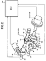
- variable valve lift mechanism 112 a , 112 b which continuously variably controls a lift amount of each intake valve 105 as well as an operating angle thereof.
- Variable valve lift mechanism 112 a and variable valve timing mechanism 113 a are combined with each other, and variable valve lift mechanism 112 b and variable valve timing mechanisms 113 b are combined with each other, so that a variable valve actuation device for intake valves 105 in respective banks is configured.
- Electronic control unit 114 receives detection signals from an air flow meter 115 for detecting an intake air flow quantity of engine 101 , an accelerator sensor 116 for detecting a depression amount of an accelerator pedal, a crank angle sensor 117 for detecting a rotating angle of a crankshaft, a throttle sensor 118 for detecting an opening TVO of a throttle valve 104 a , a water temperature sensor 119 for detecting the cooling water temperature of engine 101 , and an oxygen sensor 111 a , 111 b for detecting an air-fuel ratio in each bank, based on the oxygen concentration in the exhaust gas.
- fuel in a fuel tank 132 is supplied under pressure by a fuel pump 133 .
- fuel injection valve 131 is driven to open based on an injection pulse signal from electronic control unit 114 , the fuel of a quantity proportional to injection pulse width.
- the operating angle of intake valve 105 and the lift amount thereof are continuously changed to be increased or decreased, while the phase of the center of the operating angle of intake valve 105 being approximately fixed.
- step S 1 a reference crank angle position at each 180° if the engine is the four-cylinder engine or at each 120° if the engine is the six-cylinder engine, based on the detection signal from crank angle sensor 117 . Then, measurement of a cycle TINT at which the reference crank angle position is detected is conducted.
- step S 3 the parameter MISC is divided into a component for the right bank and that for the left bank.
- step S 4 average values MISCRAVE and MISCLAVE are obtained for each bank.
- step S 5 a torque difference BNKSTPM between both banks is obtained as a difference between the average values MISCRAVE and MISCLAVE.
- BNKSTPMS MISCRAVE ⁇ MISCLAVE
- airflow meter 115 for the right bank and air flow meter 115 for the left bank are provided for individually measuring the intake air flow quantity for each of the banks.
- K is a constant and N is an engine rotation speed.
- step S 16 the basic fuel injection quantity Tp 0 L in the left bank is subjected to the smoothing processing, and a result thereof is decided to be TPL.
- step S 17 the filling efficiency ITACR in the right bank is computed using the basic fuel injection quantity TPMAX# at the time when intake valve is fully opened.
- ITACR TPR/TPMAX#
- step S 31 the detection signal from oxygen sensor 111 a in the right bank is read out.
- step S 32 the detection signal from oxygen sensor 111 b in the left bank is read out.
- step S 35 the air-fuel ratio feedback correction coefficient ALPHAR in the right bank is subjected to the smoothing processing, and a result thereof is decided to be AVEALPR.
- a flowchart in FIG. 8 shows a control for correcting the torque difference between both banks, based on the torque difference BNKSTPMS obtained in the flowchart of FIG. 5 .
- step S 45 a most retarded angle learning value BASLRNL of the valve timing of intake valve 105 in the left bank is set to be decreased by the predetermined value HSTpV#, or a target advance angle value VTCTRL of the valve timing of intake valve 105 in the left bank is corrected to be increased by the predetermined value HSTPV#.
- step S 46 1 is set to a center phase learning completion flag FCNTLRN.
- step S 47 it is determined whether or not 1 is set to the flag FCNTLRN, namely, whether or not the learning of the characteristic dispersion in variable valve timing mechanism 113 a , 113 b is terminated.STPM
- step S 48 and the subsequent steps is executed after the learning of the characteristic dispersion in variable valve timing mechanism 113 a , 113 b is completed.
- the routine proceeds to step S 49 and the subsequent steps, to learn a lift characteristic dispersion in variable valve lift mechanism 112 a , 112 b.
- step S 89 if it is determined in step S 89 that BNKSTPAL is larger than STPIR# (BNKSTPAL>STPIR#), the routine proceeds to step S 90 in order to increase the lift amount (intake air quantity) of intake valve 105 in the left bank, whereas if it is determined in step S 91 that BNKSTPAL is smaller than STPIR# (BNKSTPAL ⁇ STPIR#), the routine proceeds to step S 92 in order to increase the lift amount (intake air quantity) of intake valve 105 in the right bank.
- the dispersion in intake air quantity between respective banks in the V-type engine is corrected.
- the learning of the characteristic dispersion can be executed for each individual bank in the V-type engine or in the horizontally opposed engine.
- the ignition timing correction shown in a flowchart of FIG. 12 is executed, so that the torque difference between each of the banks is not neglected during a period of time until the learning of the characteristic dispersion in the variable valve actuation device is completed.
- the ignition timing correction in accordance with the flowchart in FIG. 12 corresponds to the detection of the filling efficiency difference BNKSTPIC in accordance with the flowchart in FIG. 6 and the learning of the characteristic dispersion in accordance with the flowchart in FIG. 10 .
- Whether or not the learning of the dispersion in valve timing between the banks is completed can be determined, based on the learning completion flag FCNTLRN.
- step S 101 determines whether or not the learning of the valve timing dispersion was completed. If it is determined in step S 101 that the learning of the valve timing dispersion was completed, the routine proceeds to step S 102 where it is determined whether or not the learning of the lift characteristic dispersion is completed.
- step S 102 In the case where it is determined in step S 102 that the learning of the lift characteristic dispersion was completed, it is determined that the dispersion in intake air quantity between respective banks due to the characteristic dispersion in the variable valve actuation device was eliminated. Accordingly, since there is no need to eliminate the torque difference between respective banks by the ignition timing correction, the present routine is terminated without proceeding to any further steps.
- step S 104 the ignition timing in the right bank is retarded, to execute the correction for reducing the torque occurred in the right bank.
- the routine proceeds to step S 106 where the ignition timing in the left bank is retarded, to execute the correction for reducing the torque occurred in the left bank.
- a retarding correction amount is made larger as an absolute value of the filling efficiency difference BNKSPTIC becomes larger, namely, as the dispersion in intake air quantity is larger.
- a parameter to be compared with the threshold in steps S 113 and S 115 is the air-fuel ratio difference BNKSTPAL.
- a characteristic of the retarding correction amount to the air-fuel ratio difference BNKSTPAL is same as the characteristic of the retarding correction amount to the filling efficiency difference BNKSTPIC shown in FIG. 13 .
Landscapes
- Engineering & Computer Science (AREA)
- Mechanical Engineering (AREA)
- General Engineering & Computer Science (AREA)
- Chemical & Material Sciences (AREA)
- Combustion & Propulsion (AREA)
- Output Control And Ontrol Of Special Type Engine (AREA)
- Combined Controls Of Internal Combustion Engines (AREA)
Abstract
Description
[In the Case of the Six-Cylinder Engine]
BNKSTPMS=MISCRAVE−MISCLAVE
TP0R=K×QR/N
TP0L=K×QL/N
ITACR=TPR/TPMAX#
ITACL=TPR/TPMAX#
BNKSTPIC=ITACRAVE−ITACLAVE
BNKSTPAL=AVEALPR−AVEALPL
Claims (13)
Applications Claiming Priority (4)
| Application Number | Priority Date | Filing Date | Title |
|---|---|---|---|
| JP2005-090616 | 2005-03-28 | ||
| JP2005090617A JP4426993B2 (en) | 2005-03-28 | 2005-03-28 | Control device for internal combustion engine |
| JP2005-090617 | 2005-03-28 | ||
| JP2005090616A JP4399387B2 (en) | 2005-03-28 | 2005-03-28 | Control device for variable valve mechanism |
Publications (2)
| Publication Number | Publication Date |
|---|---|
| US20060219197A1 US20060219197A1 (en) | 2006-10-05 |
| US7458348B2 true US7458348B2 (en) | 2008-12-02 |
Family
ID=37026495
Family Applications (1)
| Application Number | Title | Priority Date | Filing Date |
|---|---|---|---|
| US11/389,502 Active 2026-07-20 US7458348B2 (en) | 2005-03-28 | 2006-03-27 | Method and apparatus for controlling variable valve actuation device in internal combustion engine |
Country Status (2)
| Country | Link |
|---|---|
| US (1) | US7458348B2 (en) |
| DE (1) | DE102006014358B4 (en) |
Cited By (2)
| Publication number | Priority date | Publication date | Assignee | Title |
|---|---|---|---|---|
| US20100324794A1 (en) * | 2009-06-17 | 2010-12-23 | Gm Global Technology Operations, Inc. | Torque converter control for variable valve lift powertrain systems |
| US20120116646A1 (en) * | 2010-11-04 | 2012-05-10 | Kia Motors Corporation | Method for compensating for valve lift deviation between engines equipped with cvvl mechanism |
Families Citing this family (6)
| Publication number | Priority date | Publication date | Assignee | Title |
|---|---|---|---|---|
| JP4666372B2 (en) * | 2006-01-26 | 2011-04-06 | 日立オートモティブシステムズ株式会社 | Control device for variable valve mechanism |
| JP4583362B2 (en) * | 2006-12-21 | 2010-11-17 | 日立オートモティブシステムズ株式会社 | Valve control device for internal combustion engine |
| US9752524B2 (en) * | 2014-06-25 | 2017-09-05 | Ford Global Technologies, Llc | Adaptive cam angle error estimation |
| US9541018B2 (en) * | 2014-09-15 | 2017-01-10 | Fca Us Llc | Engine cylinder bank-to-bank torque imbalance correction |
| JP2016109103A (en) * | 2014-12-10 | 2016-06-20 | トヨタ自動車株式会社 | Control device of internal combustion engine |
| JP6699702B2 (en) * | 2018-10-17 | 2020-05-27 | トヨタ自動車株式会社 | INTERNAL COMBUSTION ENGINE CONTROL DEVICE AND ITS CONTROL METHOD, LEARNING MODEL FOR CONTROLLING INTERNAL COMBUSTION ENGINE, AND LEARNING METHOD THEREOF |
Citations (7)
| Publication number | Priority date | Publication date | Assignee | Title |
|---|---|---|---|---|
| JPH1182073A (en) | 1997-09-02 | 1999-03-26 | Denso Corp | Variable valve timing control device for internal combustion engine |
| JPH11210510A (en) | 1998-01-29 | 1999-08-03 | Fuji Heavy Ind Ltd | Starting time controller for solenoid-driven valve |
| US6843230B2 (en) * | 2002-12-25 | 2005-01-18 | Hitachi Unisia Automotive, Ltd. | Control apparatus and control method of internal combustion engine |
| US6851409B2 (en) * | 2001-10-12 | 2005-02-08 | Hitachi Unisia Automotive, Ltd. | Apparatus and method for controlling intake air amount of internal combustion engine |
| US6863050B2 (en) * | 2002-07-15 | 2005-03-08 | Hitachi Unisia Automotive, Ltd. | Apparatus and method for controlling intake air amount of internal combustion engine |
| US7077085B2 (en) * | 2004-04-26 | 2006-07-18 | Nissan Motor Co., Ltd. | Variable valve control system and method for multi-cylinder internal combustion engine |
| US7191050B2 (en) * | 2002-12-02 | 2007-03-13 | Hitachi, Ltd. | Variable valve control apparatus for internal combustion engine and method thereof |
Family Cites Families (3)
| Publication number | Priority date | Publication date | Assignee | Title |
|---|---|---|---|---|
| DE19859018A1 (en) * | 1998-12-21 | 2000-06-29 | Bosch Gmbh Robert | Cylinder balancing for internal combustion engine involves influencing filling of cylinders with air or fresh gas on individual cylinder basis depending on detected torque contributions |
| DE10106921A1 (en) * | 2001-02-15 | 2002-08-22 | Bayerische Motoren Werke Ag | Method for synchronizing the filling of cylinders of an internal combustion engine, in particular a reciprocating piston internal combustion engine |
| JP3890476B2 (en) * | 2003-05-15 | 2007-03-07 | 日産自動車株式会社 | Intake valve drive control device for internal combustion engine |
-
2006
- 2006-03-27 US US11/389,502 patent/US7458348B2/en active Active
- 2006-03-28 DE DE102006014358.2A patent/DE102006014358B4/en not_active Expired - Fee Related
Patent Citations (7)
| Publication number | Priority date | Publication date | Assignee | Title |
|---|---|---|---|---|
| JPH1182073A (en) | 1997-09-02 | 1999-03-26 | Denso Corp | Variable valve timing control device for internal combustion engine |
| JPH11210510A (en) | 1998-01-29 | 1999-08-03 | Fuji Heavy Ind Ltd | Starting time controller for solenoid-driven valve |
| US6851409B2 (en) * | 2001-10-12 | 2005-02-08 | Hitachi Unisia Automotive, Ltd. | Apparatus and method for controlling intake air amount of internal combustion engine |
| US6863050B2 (en) * | 2002-07-15 | 2005-03-08 | Hitachi Unisia Automotive, Ltd. | Apparatus and method for controlling intake air amount of internal combustion engine |
| US7191050B2 (en) * | 2002-12-02 | 2007-03-13 | Hitachi, Ltd. | Variable valve control apparatus for internal combustion engine and method thereof |
| US6843230B2 (en) * | 2002-12-25 | 2005-01-18 | Hitachi Unisia Automotive, Ltd. | Control apparatus and control method of internal combustion engine |
| US7077085B2 (en) * | 2004-04-26 | 2006-07-18 | Nissan Motor Co., Ltd. | Variable valve control system and method for multi-cylinder internal combustion engine |
Cited By (4)
| Publication number | Priority date | Publication date | Assignee | Title |
|---|---|---|---|---|
| US20100324794A1 (en) * | 2009-06-17 | 2010-12-23 | Gm Global Technology Operations, Inc. | Torque converter control for variable valve lift powertrain systems |
| US8175781B2 (en) | 2009-06-17 | 2012-05-08 | GM Global Technology Operations LLC | Torque converter control for variable valve lift powertrain systems |
| US20120116646A1 (en) * | 2010-11-04 | 2012-05-10 | Kia Motors Corporation | Method for compensating for valve lift deviation between engines equipped with cvvl mechanism |
| US8857409B2 (en) * | 2010-11-04 | 2014-10-14 | Hyundai Motor Company | Method for compensating for valve lift deviation between engines equipped with CVVL mechanism |
Also Published As
| Publication number | Publication date |
|---|---|
| US20060219197A1 (en) | 2006-10-05 |
| DE102006014358B4 (en) | 2017-08-03 |
| DE102006014358A1 (en) | 2006-10-12 |
Similar Documents
| Publication | Publication Date | Title |
|---|---|---|
| US7489999B2 (en) | Control apparatus and control method for variable valve apparatus | |
| US7073493B2 (en) | Control apparatus for multi-cylinder internal combustion engine and control method | |
| US7314041B2 (en) | EGR control system for internal combustion engine | |
| JP2002256930A (en) | Intake control device for internal combustion engine | |
| US20060174854A1 (en) | Apparatus and method for controlling variable valve actuation mechanism | |
| US6983734B2 (en) | Intake flow rate detecting apparatus of internal combustion engine and method of same | |
| US7513229B2 (en) | Apparatus for and method of controlling variable valve mechanism | |
| US6792901B2 (en) | Control system of internal combustion engine | |
| US7458348B2 (en) | Method and apparatus for controlling variable valve actuation device in internal combustion engine | |
| JP4399387B2 (en) | Control device for variable valve mechanism | |
| EP1384872B1 (en) | Valve timing correction control apparatus and method for an internal combustion engine | |
| EP1770268A2 (en) | Exhaust gas recirculation fault detection system | |
| US8396646B2 (en) | Internal EGR control device for internal combustion engine | |
| US8707936B2 (en) | Control system for internal combustion engine | |
| JP4426993B2 (en) | Control device for internal combustion engine | |
| JP3011008B2 (en) | Valve timing control device for internal combustion engine | |
| JPH06229212A (en) | Valve timing control device for internal combustion engine | |
| JP5157672B2 (en) | Multi-cylinder engine air-fuel ratio control method | |
| JP4827801B2 (en) | Valve control device for internal combustion engine | |
| JPH06317129A (en) | Variable valve timing controller |
Legal Events
| Date | Code | Title | Description |
|---|---|---|---|
| AS | Assignment |
Owner name: HITACHI, LTD., JAPAN Free format text: ASSIGNMENT OF ASSIGNORS INTEREST;ASSIGNORS:MACHIDA, KENICHI;YOSHIZAWA, HIDEKAZU;REEL/FRAME:018095/0488 Effective date: 20060703 |
|
| STCF | Information on status: patent grant |
Free format text: PATENTED CASE |
|
| FEPP | Fee payment procedure |
Free format text: PAYOR NUMBER ASSIGNED (ORIGINAL EVENT CODE: ASPN); ENTITY STATUS OF PATENT OWNER: LARGE ENTITY |
|
| FPAY | Fee payment |
Year of fee payment: 4 |
|
| FPAY | Fee payment |
Year of fee payment: 8 |
|
| MAFP | Maintenance fee payment |
Free format text: PAYMENT OF MAINTENANCE FEE, 12TH YEAR, LARGE ENTITY (ORIGINAL EVENT CODE: M1553); ENTITY STATUS OF PATENT OWNER: LARGE ENTITY Year of fee payment: 12 |
|
| AS | Assignment |
Owner name: HITACHI AUTOMOTIVE SYSTEMS, LTD., JAPAN Free format text: DEMERGER;ASSIGNOR:HITACHI, LTD.;REEL/FRAME:058744/0813 Effective date: 20090701 Owner name: HITACHI ASTEMO, LTD., JAPAN Free format text: CHANGE OF NAME;ASSIGNOR:HITACHI AUTOMOTIVE SYSTEMS, LTD.;REEL/FRAME:058758/0776 Effective date: 20210101 |