US7450897B2 - Exit tray and image forming apparatus including the same - Google Patents
Exit tray and image forming apparatus including the same Download PDFInfo
- Publication number
- US7450897B2 US7450897B2 US11/106,454 US10645405A US7450897B2 US 7450897 B2 US7450897 B2 US 7450897B2 US 10645405 A US10645405 A US 10645405A US 7450897 B2 US7450897 B2 US 7450897B2
- Authority
- US
- United States
- Prior art keywords
- plate
- forming apparatus
- image forming
- exit tray
- paper
- Prior art date
- Legal status (The legal status is an assumption and is not a legal conclusion. Google has not performed a legal analysis and makes no representation as to the accuracy of the status listed.)
- Expired - Fee Related, expires
Links
Images


Classifications
-
- B—PERFORMING OPERATIONS; TRANSPORTING
- B41—PRINTING; LINING MACHINES; TYPEWRITERS; STAMPS
- B41J—TYPEWRITERS; SELECTIVE PRINTING MECHANISMS, i.e. MECHANISMS PRINTING OTHERWISE THAN FROM A FORME; CORRECTION OF TYPOGRAPHICAL ERRORS
- B41J13/00—Devices or arrangements of selective printing mechanisms, e.g. ink-jet printers or thermal printers, specially adapted for supporting or handling copy material in short lengths, e.g. sheets
- B41J13/10—Sheet holders, retainers, movable guides, or stationary guides
- B41J13/106—Sheet holders, retainers, movable guides, or stationary guides for the sheet output section
-
- H—ELECTRICITY
- H04—ELECTRIC COMMUNICATION TECHNIQUE
- H04N—PICTORIAL COMMUNICATION, e.g. TELEVISION
- H04N1/00—Scanning, transmission or reproduction of documents or the like, e.g. facsimile transmission; Details thereof
- H04N1/00567—Handling of original or reproduction media, e.g. cutting, separating, stacking
-
- G—PHYSICS
- G03—PHOTOGRAPHY; CINEMATOGRAPHY; ANALOGOUS TECHNIQUES USING WAVES OTHER THAN OPTICAL WAVES; ELECTROGRAPHY; HOLOGRAPHY
- G03G—ELECTROGRAPHY; ELECTROPHOTOGRAPHY; MAGNETOGRAPHY
- G03G15/00—Apparatus for electrographic processes using a charge pattern
- G03G15/65—Apparatus which relate to the handling of copy material
- G03G15/6552—Means for discharging uncollated sheet copy material, e.g. discharging rollers, exit trays
-
- H—ELECTRICITY
- H04—ELECTRIC COMMUNICATION TECHNIQUE
- H04N—PICTORIAL COMMUNICATION, e.g. TELEVISION
- H04N1/00—Scanning, transmission or reproduction of documents or the like, e.g. facsimile transmission; Details thereof
- H04N1/00567—Handling of original or reproduction media, e.g. cutting, separating, stacking
- H04N1/0057—Conveying sheets before or after scanning
- H04N1/00591—Conveying sheets before or after scanning from the scanning position
-
- H—ELECTRICITY
- H04—ELECTRIC COMMUNICATION TECHNIQUE
- H04N—PICTORIAL COMMUNICATION, e.g. TELEVISION
- H04N1/00—Scanning, transmission or reproduction of documents or the like, e.g. facsimile transmission; Details thereof
- H04N1/00567—Handling of original or reproduction media, e.g. cutting, separating, stacking
- H04N1/00631—Ejecting or stacking
-
- H—ELECTRICITY
- H04—ELECTRIC COMMUNICATION TECHNIQUE
- H04N—PICTORIAL COMMUNICATION, e.g. TELEVISION
- H04N1/00—Scanning, transmission or reproduction of documents or the like, e.g. facsimile transmission; Details thereof
- H04N1/00567—Handling of original or reproduction media, e.g. cutting, separating, stacking
- H04N1/00641—Sorting, reordering or inverting
-
- G—PHYSICS
- G03—PHOTOGRAPHY; CINEMATOGRAPHY; ANALOGOUS TECHNIQUES USING WAVES OTHER THAN OPTICAL WAVES; ELECTROGRAPHY; HOLOGRAPHY
- G03G—ELECTROGRAPHY; ELECTROPHOTOGRAPHY; MAGNETOGRAPHY
- G03G2215/00—Apparatus for electrophotographic processes
- G03G2215/00362—Apparatus for electrophotographic processes relating to the copy medium handling
- G03G2215/00367—The feeding path segment where particular handling of the copy medium occurs, segments being adjacent and non-overlapping. Each segment is identified by the most downstream point in the segment, so that for instance the segment labelled "Fixing device" is referring to the path between the "Transfer device" and the "Fixing device"
- G03G2215/00417—Post-fixing device
- G03G2215/00421—Discharging tray, e.g. devices stabilising the quality of the copy medium, postfixing-treatment, inverting, sorting
-
- H—ELECTRICITY
- H04—ELECTRIC COMMUNICATION TECHNIQUE
- H04N—PICTORIAL COMMUNICATION, e.g. TELEVISION
- H04N1/00—Scanning, transmission or reproduction of documents or the like, e.g. facsimile transmission; Details thereof
- H04N1/04—Scanning arrangements, i.e. arrangements for the displacement of active reading or reproducing elements relative to the original or reproducing medium, or vice versa
- H04N1/12—Scanning arrangements, i.e. arrangements for the displacement of active reading or reproducing elements relative to the original or reproducing medium, or vice versa using the sheet-feed movement or the medium-advance or the drum-rotation movement as the slow scanning component, e.g. arrangements for the main-scanning
Definitions
- the present invention relates to an image forming apparatus. More particularly, the present invention relates to an image forming apparatus that prints and scans.
- an image forming apparatus receives an image signal and prints the image signal as a visible image on a sheet of paper.
- an image forming apparatus has been used as a multi-function product that combines the functions of a printer, facsimile, and scanner.
- the multi-function product can print an image, as well as scan an image recorded on a document and reproduce the image on a sheet of paper or a display by converting the image into digital image information.
- FIG. 1 illustrates a conventional multi-function product that uses an inkjet recording head that ejects ink onto a sheet of paper to print an image.
- the image forming apparatus 10 includes a body 11 having a scanning unit (not shown) that scans an image recorded on a document and a printing unit that prints an image on a sheet of paper.
- An operating panel 12 includes a plurality of function keys and a display on the front of the body 11 .
- a document feed tray 15 that receives documents to be scanned is disposed in the rear of the operating panel 12 . Sheets of paper to be printed are stacked on a paper feed tray 17 disposed behind the document feed tray 15 .
- Print sheets of paper are stacked on a paper exit tray 20 , and scanned documents are stacked on a document exit tray 22 .
- the paper exit tray 20 and the document exit tray 22 are disposed under the operating panel 12 .
- the image forming apparatus 10 may be placed on a desk when used in an office or a house.
- the paper exit tray 20 and the document exit tray 22 remain protruded from the body 11 even when the image forming apparatus 10 is not printing an image or scanning a document. Accordingly, the protruded paper exit tray 20 and the document exit tray 22 hinder efficient use of desk space and thus undermines work efficiency.
- the paper exit tray 20 and the document exit tray 22 must be detached from the body 11 and packed separately in the box. Accordingly, a large box is required to pack the image forming apparatus 10 , thereby decreasing shipping efficiency while increasing shipping costs of the image forming apparatus 10 .
- the present invention relates to an exit tray that is insertable into a body of an image forming apparatus when printing or scanning is not performed.
- the present invention also relates to an exit tray including a paper exit plate upon which printed sheets of paper exiting from a body of an image forming apparatus are stacked, and a document exit plate upon which scanned documents exiting from the body are stacked.
- the paper and document exit plates are coupled to one another to be inserted together into the body.
- an exit tray is loaded into a body of an image forming apparatus having printing and scanning functions. Sheets of printed paper and scanned documents exiting from the body are stacked upon the exit tray, which includes a first plate insertable in the body and a second plate pivotable from the first plate by a predetermined distance and that may approach the first plate.
- Printed sheets of paper exiting from the body are stacked on either the first plate or the second plate. Scanned documents exiting from the body are stacked on the plate not receiving the printed sheets of paper.
- the exit tray may further include a coupling member, one side of which is hinge-joined to the first plate and the other side of which is hinge-joined to the second plate.
- a first tension spring is wound around a region where the first plate is hinge-joined to the coupling member.
- a second tension spring is wound around a region where the second plate is hinge-joined to the coupling member.
- the second plate may be elastically biased to be separated from the first plate by the predetermined distance.
- the coupling member may be diagonally coupled to the first plate.
- the coupling member may be coupled to a side of each of the first plate and the second plate to prevent obstructing or interfering the sheets of paper or documents stacked thereon.
- an image forming apparatus includes a body having a printing unit printing an image on a sheet of paper and a scanning unit scanning an image recorded on a document.
- An exit tray is adapted to stackably receive sheets of paper with images printed by the printing unit and documents with images scanned by the scanning unit exiting from the body.
- the exit tray includes a first plate insertable in the body and a second plate pivotable from the first plate by a predetermined distance and that may approach the first plate.
- Printed sheets of paper exiting from the body are stacked on either the first plate or the second plate. Scanned documents exiting from the body are stacked on the plate not receiving the printed sheets.
- the exit tray may further include a coupling member, one side of which is hinge-joined to the first plate and the other side of which is hinge-joined to the second plate.
- a first tension spring is wound around a region where the first plate is hinge-joined to the coupling member.
- a second tension spring is wound around a region where the second plate is hinge-joined to the coupling member.
- the second plate may be elastically biased to be separated from the first plate by the predetermined distance.
- the second plate may approach the first plate when the exit tray is inserted in the body.
- the coupling member of the exit tray may be diagonally coupled to the first plate.
- the coupling member of the exit tray may be coupled to a side of each of the first plate and the second plate to prevent obstructing or interfering the sheets of paper or documents stacked thereon.
- the body may include a member, and, when the exit tray is inserted in the body, the second plate may slide in contact with the member and approach the first plate.
- Gear teeth may be formed on a bottom of the first plate.
- the body may include a pinion gear engaging the gear teeth of the first plate.
- the exit tray may be inserted in or pulled out of the body according to the direction of rotation of the pinion gear.
- the pinion gear may rotate in a direction in which the exit tray is inserted in the body when printing or scanning is not performed for a predetermined period of time.
- the pinion gear may rotate in a direction in which the exit tray protrudes from the body when printing or scanning is performed.
- FIG. 1 is a perspective view of a conventional image forming apparatus
- FIG. 2 is a perspective view of an image forming apparatus according to a first embodiment of the present invention
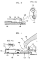
- FIG. 3 is a sectional view of an exit tray taken along line III-III of FIG. 2 ;
- FIG. 3A is an enlarged elevational view of the first and second hinges of the exit tray of FIG. 3 ;
- FIG. 4 is an elevational view in partial cross section of the image forming apparatus when the exit tray protrudes from a body of the image forming apparatus;
- FIG. 4A is an enlarged elevational view of a tension spring of FIG. 4 ;
- FIG. 5 is an elevational view in partial cross section of the image forming apparatus when the exit tray is inserted in the body of the image forming apparatus;
- FIG. 6 is an elevational view in partial cross section of an image forming apparatus according to a second embodiment of the present invention.
- FIG. 2 is a perspective view of an image forming apparatus according to a first embodiment of the present invention.
- FIGS. 3 and 3A are sectional views of an exit tray taken along line III-III of FIG. 2 .
- FIGS. 4 and 5 illustrate the image forming apparatus of FIG. 2 .
- FIG. 4 illustrates the image forming apparatus when the exit tray protrudes from a body of the image forming apparatus.
- FIG. 5 illustrates the image forming apparatus when the exit tray is inserted into the body of the image forming apparatus.
- the image forming apparatus 100 includes a body 101 having a scanning unit (not shown) that scans an image recorded on a document and a printing unit that prints an image on a sheet of paper.
- An operating panel 102 includes a plurality of function keys and a display on the front of the body 101 .
- the scanning unit may include a contact image sensor (CIS) or a charge coupled device (CCD).
- the printing unit may include an inkjet recording head ejecting ink onto a sheet of paper to form an image on the sheet of paper.
- a document feed tray 105 whereon documents to be scanned are stacked is disposed in the rear of the operating panel 102 .
- a paper feed tray 107 whereon sheets of paper to be printed are stacked is disposed behind the document feed tray 105 .
- Scanned documents and printed papers exit through an exit aperture 120 disposed under the operating panel 102 after passing through the body 101 .
- An exit tray 130 whereon the documents or sheets of paper exiting through the exit aperture 120 are stacked is also disposed under the operating panel 102 .
- the exit tray 130 includes a first plate 132 upon which sheets of paper exiting through the exit aperture 120 are stacked and a pair of second plates 135 disposed above the first plate 132 upon which documents exiting through the exit aperture 120 are stacked.
- the first plate 132 may be inserted in the body 101 or pulled out of the body 101 .
- Each of the second plates 135 is coupled to the first plate 132 by each of coupling members 137 .
- the coupling member 137 is hingedly connected to the first plate 132 to form a first hinge joint 138
- the other side of the coupling member 137 is hingedly connected to the second plate 135 to form a second hinge joint 139
- the first hinge joint 138 controls the coupling member 137 to rotate at an angle ranging from 0 to 90 degrees with respect to the first plate 132
- the second hinge joint 139 controls the second plate 135 to rotate at an angle ranging from 0 to 90 degrees.
- the angle range of the second hinge joint is substantially the same as the angle range within which the coupling member 137 rotates with respect to the first plate 132 .
- a rotation angle may also be controlled by forming stoppers in the first and second hinge joints 138 and 139 , which, however, are not described in this disclosure since it is obvious to those skilled in the art.
- the second plate 135 may be disposed a predetermined distance above the first plate 132 as indicated by a solid line or attached to the first plate 132 as indicated by a chain double-dashed line in FIG. 3 .
- the coupling member 137 is diagonally slanted with respect to the first plate 132 (not clearly illustrated in FIGS. 2 and 3 ).
- a surface 133 formed in a portion of the first plate 132 accommodates the second plate 135 .
- a first tension spring 141 is wound around the first hinge joint 138 and elastically biases the coupling member 137 to stand diagonally with respect to the first plate 132 .
- a second tension spring 144 is wound around the second hinge joint 139 and elastically biases the second plate 135 to extend roughly horizontally at a predetermined angle with respect to the coupling member 137 .
- the second plate 135 is elastically biased to be separated from the first plate 132 by a predetermined distance by the first and second hinge joints 138 and 139 of the coupling member 137 and the first and second tension springs 141 and 144 wound around the first and second hinge joints 138 and 139 .
- the coupling member 137 is hingedly-connected to a side of each of the first plate 132 and the second plate 135 to not obstruct or interfere with the sheets of paper exiting from the body 101 and stacked on the first plate 132 .
- the second plate 135 is slanted such that a distance between the second plate 135 and the first plate 132 becomes greater in a direction toward the front of the second plate 135 (that is, away from the body 101 ). Therefore, a user may easily take out sheets of paper stacked on the first plate 132 without being bothered by the second plate 135 .
- a member 117 is disposed inside the exit aperture 120 .
- a sloping surface 118 is formed on the lower front of the member 117 .
- the coupling member 137 Since the coupling member 137 is slanted diagonally with respect to the first plate 132 , when the second plate 135 contacts the member 117 , the coupling member 137 rotates toward the first plate 132 to facilitate insertion of the exit tray 130 in the body 101 .
- the second plate 135 elastically biased by the first and second tension springs 141 and 144 slides up the sloping surface 118 while contacting the sloping surface 118 and is gradually separated from the first plate 132 .
- the first plate 132 is pulled out until the second plate 135 is pulled out of the body 101 , the second plate 135 is separated from the first plate 132 by the same distance as the second plate 135 was initially separated from the first plate 132 .
- a first path along which scanned documents exit is preferably formed above the member 117 .
- a document exit roller 110 forcing the scanned documents to exit is disposed on the first path.
- a second path along which printed sheets of paper exit is preferably formed under the member 117 .
- a paper exit roller 115 forcing the printed sheets of paper to exit is disposed on the second path.
- the image forming apparatus 100 When a user desires to print images using the image forming apparatus 100 , the user must stack sheets of paper on the paper feed tray 107 and input a print command. Then, the sheets of paper stacked on the paper feed tray 107 are fed into the body 101 one by one. The sheets of paper fed into the body 101 pass through the printing unit (not shown), which, in turn, prints images on the sheets of paper. The printed sheets of paper are forced to exit from the body 101 by the paper exit roller 115 and are stacked on the first plate 132 .
- the user When a user desires to scan images recorded on documents using the image forming apparatus 100 , the user stacks the documents on the document feed tray 105 and inputs a scan command. Then, the documents stacked on the document feed tray 105 are fed into the body 101 one by one. The documents fed into the body 101 pass through the scanning unit (not shown), which, in turn, scans the images on the documents. The scanned documents are forced to exit from the body 101 by the document exit roller 110 and are stacked on the second plate 135 .
- the first plate 132 may be pushed into the body 101 .
- the second plate 135 enters the body 101 along with the first plate 132 .
- the second plate 135 slides down and is pressed under the sloping surface 118 of the member 117 by contacting the sloping surface 118 , thereby causing the second plate 135 to approach the first plate 132 .
- the exit tray 130 is inserted into the body 101 .
- the first plate 132 is pulled forward (that is, out from a stored position within the body 101 ).
- the second plate 135 is pulled forward along with the first plate 132 .
- the second plate 135 is separated from the first plate 132 by the same distance as the second plate 135 was initially separated from the first plate 132 by the restoration force of the first and second tension springs 141 and 144 . Therefore, printed sheets of paper and scanned documents may be stacked separately.
- FIG. 6 is a sectional view of an image forming apparatus 200 according to a second embodiment of the present invention.
- the image forming apparatus 200 according to the second embodiment of the present invention includes an operating panel 202 on the front of a body 201 and an exit tray 230 that is insertable in the body 201 under the operating panel 202 .
- a member 217 , a document exit roller 210 , and a paper exit roller 215 are disposed inside an exit aperture 220 of the body 201 of the image forming apparatus 200 .
- the exit tray 230 also includes a first plate 232 , a second plate 235 , a coupling member 237 coupling the first and second plates 232 and 235 , a first tension spring 241 , and a second tension spring 244 .
- a gear portion 234 with teeth is disposed on a bottom surface of the first plate 232 .
- a pinion gear 225 adapted to engage the gear portion 234 is disposed in the body 201 .
- the pinion gear 225 may be connected to a motor (not shown), which provides a turning force to the paper exit roller 215 and to the pinion gear 225 .
- the pinion gear 225 may receive the turning force from a separate motor installed to drive only the pinion gear 225 .
- the motor providing the turning force to the pinion gear 225 may automatically rotate the pinion gear 225 in a direction in which the exit tray 230 is inserted into the body 210 to the stored position.
- the motor may automatically rotate the pinion gear 235 in a direction to move the exit tray 230 out of the body 201 to a protruded position, as shown in FIG. 6 .
- the first plate 232 is moved into the body 201 .
- the second plate 235 is also moved into the body 201 along with the first plate 232 by contacting the member 217 , thereby approaching the first plate 232 .
- the exit tray 230 is inserted in the body 201 .
- the first plate 232 and the second plate 235 which is connected to the first plate 232 , are moved out of the body 201 .
- the second plate 235 is separated from the first plate 232 by substantially the same distance as the second plate 235 was initially separated from the first plate 232 by the restoration force of the first and second tension springs 241 and 244 .
- the exit tray 230 is in a protruded position (that is, the exit tray extends outwardly from the body 201 ).
- An exit tray and an image forming apparatus have the following advantages.
Abstract
Description
Claims (20)
Applications Claiming Priority (2)
| Application Number | Priority Date | Filing Date | Title |
|---|---|---|---|
| KR1020040038749A KR100619024B1 (en) | 2004-05-29 | 2004-05-29 | Exit tray and image forming apparatus therewith |
| KR10-2004-0038749 | 2004-05-29 |
Publications (2)
| Publication Number | Publication Date |
|---|---|
| US20050265763A1 US20050265763A1 (en) | 2005-12-01 |
| US7450897B2 true US7450897B2 (en) | 2008-11-11 |
Family
ID=35425416
Family Applications (1)
| Application Number | Title | Priority Date | Filing Date |
|---|---|---|---|
| US11/106,454 Expired - Fee Related US7450897B2 (en) | 2004-05-29 | 2005-04-15 | Exit tray and image forming apparatus including the same |
Country Status (2)
| Country | Link |
|---|---|
| US (1) | US7450897B2 (en) |
| KR (1) | KR100619024B1 (en) |
Citations (12)
| Publication number | Priority date | Publication date | Assignee | Title |
|---|---|---|---|---|
| US4622563A (en) * | 1983-07-05 | 1986-11-11 | Kabushiki Kaisha Toshiba | Printing apparatus with multiple ribbon cassettes holder |
| JPH0517063A (en) | 1991-07-11 | 1993-01-26 | Ricoh Co Ltd | Sending-out and accommodation of paper sheet tray and device therefor |
| JPH05278920A (en) | 1992-04-03 | 1993-10-26 | Casio Electron Mfg Co Ltd | Sheet tray |
| JPH05278921A (en) | 1992-04-03 | 1993-10-26 | Casio Electron Mfg Co Ltd | Sheet exhaust tray |
| JPH0812163A (en) | 1994-06-28 | 1996-01-16 | Murata Mach Ltd | Facsimile device |
| JPH10150513A (en) | 1996-11-15 | 1998-06-02 | Mita Ind Co Ltd | Image-forming device |
| US5774139A (en) * | 1995-07-31 | 1998-06-30 | Hewlett-Packard Company | Vertical axis service station adjustment device and method |
| JP2000281260A (en) | 1999-03-30 | 2000-10-10 | Murata Mach Ltd | Picture image forming device |
| JP2000327203A (en) | 1999-05-19 | 2000-11-28 | Canon Inc | Automatic paper discharge tray device and recording device |
| US6231043B1 (en) * | 1999-07-29 | 2001-05-15 | Lexmark International, Inc. | Retractable exit tray for imaging apparatus |
| US6659454B1 (en) * | 2001-08-10 | 2003-12-09 | Lexmark International, Inc. | Printer exit tray and computer printer having an exit tray |
| US20040062587A1 (en) * | 2002-07-10 | 2004-04-01 | Canon Kabushiki Kaisha | Recording apparatus |
-
2004
- 2004-05-29 KR KR1020040038749A patent/KR100619024B1/en active IP Right Grant
-
2005
- 2005-04-15 US US11/106,454 patent/US7450897B2/en not_active Expired - Fee Related
Patent Citations (12)
| Publication number | Priority date | Publication date | Assignee | Title |
|---|---|---|---|---|
| US4622563A (en) * | 1983-07-05 | 1986-11-11 | Kabushiki Kaisha Toshiba | Printing apparatus with multiple ribbon cassettes holder |
| JPH0517063A (en) | 1991-07-11 | 1993-01-26 | Ricoh Co Ltd | Sending-out and accommodation of paper sheet tray and device therefor |
| JPH05278920A (en) | 1992-04-03 | 1993-10-26 | Casio Electron Mfg Co Ltd | Sheet tray |
| JPH05278921A (en) | 1992-04-03 | 1993-10-26 | Casio Electron Mfg Co Ltd | Sheet exhaust tray |
| JPH0812163A (en) | 1994-06-28 | 1996-01-16 | Murata Mach Ltd | Facsimile device |
| US5774139A (en) * | 1995-07-31 | 1998-06-30 | Hewlett-Packard Company | Vertical axis service station adjustment device and method |
| JPH10150513A (en) | 1996-11-15 | 1998-06-02 | Mita Ind Co Ltd | Image-forming device |
| JP2000281260A (en) | 1999-03-30 | 2000-10-10 | Murata Mach Ltd | Picture image forming device |
| JP2000327203A (en) | 1999-05-19 | 2000-11-28 | Canon Inc | Automatic paper discharge tray device and recording device |
| US6231043B1 (en) * | 1999-07-29 | 2001-05-15 | Lexmark International, Inc. | Retractable exit tray for imaging apparatus |
| US6659454B1 (en) * | 2001-08-10 | 2003-12-09 | Lexmark International, Inc. | Printer exit tray and computer printer having an exit tray |
| US20040062587A1 (en) * | 2002-07-10 | 2004-04-01 | Canon Kabushiki Kaisha | Recording apparatus |
Also Published As
| Publication number | Publication date |
|---|---|
| KR100619024B1 (en) | 2006-08-31 |
| KR20050113526A (en) | 2005-12-02 |
| US20050265763A1 (en) | 2005-12-01 |
Similar Documents
| Publication | Publication Date | Title |
|---|---|---|
| JP4609579B2 (en) | Image recording device | |
| US7426113B2 (en) | Electronic device | |
| JP2009179447A (en) | Sheet conveying device and image recording device with the same | |
| US20060177237A1 (en) | Image forming apparatus and image reading apparatus | |
| JP4581711B2 (en) | Image recording device | |
| JP2004203513A (en) | Sheet feeding device and image reading/recording device equipped with the same | |
| JP2009007139A (en) | Image recording device | |
| JP2009007106A (en) | Image recording device | |
| US7605956B2 (en) | Multi-function machine having jam removing apparatus and jam removing method thereof | |
| US7450897B2 (en) | Exit tray and image forming apparatus including the same | |
| CN117055313A (en) | Image forming apparatus | |
| US10481549B2 (en) | Attachment unit | |
| JP2005311627A (en) | Image forming apparatus | |
| JP4581707B2 (en) | Image recording device | |
| US7547012B2 (en) | Sheet feeder image forming device | |
| US20060087069A1 (en) | Medium feeding device and recording apparatus and liquid ejecting apparatus, having medium feeding device | |
| JP4306511B2 (en) | Medium feeding device | |
| JP2006117395A (en) | Medium feeding device and recording device | |
| JP2006117384A (en) | Medium feeding device, and recording device and liquid injection device provided with the same medium feeding device | |
| JP2006205377A (en) | Inkjet recording device | |
| JP2006211495A (en) | Image recording device | |
| JP2006117362A (en) | Medium feeding device and recording device and liquid injection device equipped with the medium feeding device | |
| JP2007039234A (en) | Printer | |
| JP3397714B2 (en) | Recording device and image processing device | |
| JP4407463B2 (en) | Recording device |
Legal Events
| Date | Code | Title | Description |
|---|---|---|---|
| AS | Assignment |
Owner name: SAMSUNG ELECTRONICS CO., LTD., KOREA, REPUBLIC OF Free format text: ASSIGNMENT OF ASSIGNORS INTEREST;ASSIGNOR:KIM, HO-GON;REEL/FRAME:016484/0931 Effective date: 20050414 |
|
| STCF | Information on status: patent grant |
Free format text: PATENTED CASE |
|
| FEPP | Fee payment procedure |
Free format text: PAYOR NUMBER ASSIGNED (ORIGINAL EVENT CODE: ASPN); ENTITY STATUS OF PATENT OWNER: LARGE ENTITY |
|
| FEPP | Fee payment procedure |
Free format text: PAYER NUMBER DE-ASSIGNED (ORIGINAL EVENT CODE: RMPN); ENTITY STATUS OF PATENT OWNER: LARGE ENTITY Free format text: PAYOR NUMBER ASSIGNED (ORIGINAL EVENT CODE: ASPN); ENTITY STATUS OF PATENT OWNER: LARGE ENTITY |
|
| FPAY | Fee payment |
Year of fee payment: 4 |
|
| FPAY | Fee payment |
Year of fee payment: 8 |
|
| AS | Assignment |
Owner name: S-PRINTING SOLUTION CO., LTD., KOREA, REPUBLIC OF Free format text: ASSIGNMENT OF ASSIGNORS INTEREST;ASSIGNOR:SAMSUNG ELECTRONICS CO., LTD;REEL/FRAME:041852/0125 Effective date: 20161104 |
|
| AS | Assignment |
Owner name: HP PRINTING KOREA CO., LTD., KOREA, REPUBLIC OF Free format text: CHANGE OF NAME;ASSIGNOR:S-PRINTING SOLUTION CO., LTD.;REEL/FRAME:047370/0405 Effective date: 20180316 |
|
| AS | Assignment |
Owner name: HP PRINTING KOREA CO., LTD., KOREA, REPUBLIC OF Free format text: CORRECTIVE ASSIGNMENT TO CORRECT THE DOCUMENTATION EVIDENCING THE CHANGE OF NAME PREVIOUSLY RECORDED ON REEL 047370 FRAME 0405. ASSIGNOR(S) HEREBY CONFIRMS THE CHANGE OF NAME;ASSIGNOR:S-PRINTING SOLUTION CO., LTD.;REEL/FRAME:047769/0001 Effective date: 20180316 |
|
| AS | Assignment |
Owner name: HP PRINTING KOREA CO., LTD., KOREA, REPUBLIC OF Free format text: CHANGE OF LEGAL ENTITY EFFECTIVE AUG. 31, 2018;ASSIGNOR:HP PRINTING KOREA CO., LTD.;REEL/FRAME:050938/0139 Effective date: 20190611 |
|
| AS | Assignment |
Owner name: HEWLETT-PACKARD DEVELOPMENT COMPANY, L.P., TEXAS Free format text: CONFIRMATORY ASSIGNMENT EFFECTIVE NOVEMBER 1, 2018;ASSIGNOR:HP PRINTING KOREA CO., LTD.;REEL/FRAME:050747/0080 Effective date: 20190826 |
|
| FEPP | Fee payment procedure |
Free format text: MAINTENANCE FEE REMINDER MAILED (ORIGINAL EVENT CODE: REM.); ENTITY STATUS OF PATENT OWNER: LARGE ENTITY |
|
| LAPS | Lapse for failure to pay maintenance fees |
Free format text: PATENT EXPIRED FOR FAILURE TO PAY MAINTENANCE FEES (ORIGINAL EVENT CODE: EXP.); ENTITY STATUS OF PATENT OWNER: LARGE ENTITY |
|
| STCH | Information on status: patent discontinuation |
Free format text: PATENT EXPIRED DUE TO NONPAYMENT OF MAINTENANCE FEES UNDER 37 CFR 1.362 |
|
| FP | Lapsed due to failure to pay maintenance fee |
Effective date: 20201111 |