US7441530B2 - Optimal heat engine - Google Patents
Optimal heat engine Download PDFInfo
- Publication number
- US7441530B2 US7441530B2 US11/129,783 US12978305A US7441530B2 US 7441530 B2 US7441530 B2 US 7441530B2 US 12978305 A US12978305 A US 12978305A US 7441530 B2 US7441530 B2 US 7441530B2
- Authority
- US
- United States
- Prior art keywords
- piston
- force
- improvement
- dependent force
- dependent
- Prior art date
- Legal status (The legal status is an assumption and is not a legal conclusion. Google has not performed a legal analysis and makes no representation as to the accuracy of the status listed.)
- Expired - Fee Related, expires
Links
Images


Classifications
-
- F—MECHANICAL ENGINEERING; LIGHTING; HEATING; WEAPONS; BLASTING
- F02—COMBUSTION ENGINES; HOT-GAS OR COMBUSTION-PRODUCT ENGINE PLANTS
- F02B—INTERNAL-COMBUSTION PISTON ENGINES; COMBUSTION ENGINES IN GENERAL
- F02B75/00—Other engines
- F02B75/32—Engines characterised by connections between pistons and main shafts and not specific to preceding main groups
Definitions
- the invention relates, in general, to reciprocating machines for converting thermal energy into mechanical force or, conversely, using mechanical work to transfer thermal energy from one region to another.
- the invention relates to mechanisms designed to produce position-dependent conservative forces to counter the conservative forces that arise from the change in volume of the machine's working medium.
- Conservative forces are defined as those forces that are a direct result of a potential energy field and, therefore, are a function only of position. As a consequence, it is sufficient and necessary that they derive from the gradient of a potential energy function.
- the work a conservative force does on an object in moving it from point A to B is path independent—i.e., it depends only on the end points of the motion.
- the force of gravity and the spring force are conservative forces owing to their dependence only on a parameter of position.
- a spinning flywheel represents kinetic energy that is a function not of its orientation, but of a change in its orientation as a function of time. Therefore, a force resulting from a spinning flywheel cannot be the gradient of a potential energy function and, subsequently, cannot be a conservative force.
- Other examples include dissipative forces such as friction and air-resistance which are independent of the direction of travel and, therefore, cannot derive from the gradient of a function.
- a reciprocating machine consists of a device that includes a moveable member, such as a piston, subject to a variety of configurational forces.
- Most reciprocating machines are designed to perform a particular function and their functionality is the main focus of machine design. When efficiency is of concern, the design is normally optimized by reducing frictional forces and heat losses while retaining the desired functionality of the machine.
- Reciprocating heat engines are characterized by forces arising from the compression or decompression of the working medium in response to a displacement of the reciprocating member, i.e., the piston.
- the working medium may take the form of a gas, such as air or a fuel-air mixture, a liquid, a solid, or any combination thereof. If the reciprocating motion is periodic in nature, that is predictable as to the location of the reciprocating member as a function of time, then the forces are equally so and the result is a force that can be determined solely by the location of the reciprocating member. This meets the requirement of being a conservative force.
- thermodynamics The efficiency of reciprocating heat engines is analyzed conventionally using the applicable laws of thermodynamics.
- the efficiency of such a cyclical process is defined as the ratio of the net useful energy change produced to the energy input required to produce that change.
- the input consists of heat, Q in
- the output is the net work, ⁇ W, performed by the engine. Therefore, engine efficiency is given by
- FIG. 2 The cyclical operation of heat engines has been traditionally analyzed using pressure-volume (PV) diagrams, as illustrated in FIG. 2 .
- Heat engines operate clockwise around the diagram while refrigerators and compressors proceed counter-clockwise.
- segment I of the cycle depicted in the figure which is a realistic hybrid of the ideal Otto and Diesel cycles described in the literature, corresponds to the adiabatic compression of the working medium in the engine.
- Segment II is an increase in pressure caused by the heating of the working medium under constant volume conditions.
- segment II is associated with the Otto-cycle, spark-ignition of the fuel-air mixture that comprises the working medium.
- Segment III represents heating of the working medium where expansion and heat addition are balanced to maintain constant pressure.
- Segment IV corresponds to the adiabatic expansion of the working medium caused by the very high pressure produced by the heating of the working medium.
- segment V is the constant-volume reduction in the pressure and temperature of the working medium to return it to its initial state. This segment is identified with the process of exhausting spent fuel and replacing it with a fresh fuel-air mixture in internal combustion engines.
- Equation 6 the area enclosed by the diagram measures the net work done in a cycle. This has been historically interpreted as being consistent with the notion that conservative forces have no net effect on the efficiency of the system. That is, since the work associated with the area under the segment labeled I is common with the work associated with segments III and IV, but opposite in sign, its contribution to the total work done in a cycle is reduced to zero. Therefore, it has been considered not to have any effect on the efficiency of the system.
- the Otto-cycle engine typically implemented as today's spark-ignition gasoline engine, is analyzed, under an ideal implementation, as if points 3 and 4 of the curve of FIG. 2 were coincident.
- the ideal Diesel cycle is assumed to have coincident points 2 and 3 . Both ideal cases are only theoretical in nature, with actual operation of either engine tending more toward the mixed case shown in the figure.
- the compression ratio of a reciprocating piston engine is defined as
- FIG. 3 shows efficiency data (the square data points 14 are from R. V. Kerley and K. W. Thurston, The Indicated Performance of Otto - Cycle Engines , SAE Technical Papers #620508, 1962; the round data points 16 are from D. F. Caris and E. E. Nelson, A New Look at High Compression Engines, SAE Technical Papers #590015, 1959.) and the predictive curves of the theoretical air-cycle and fuel/air-cycle models all as a function of compression ratio.
- the air-cycle curve 10 is simply a plot of Equation 8 using a value of 1.34 for the ratio-of specific heats as extracted from Caris, et al.
- thermodynamic efficiency of combustion engines all parameters affecting the thermodynamic efficiency of combustion engines are well understood and that further improvements can only be achieved through incremental enhancements to the existing structures and materials already in use, rather than a better theoretical understanding of the fundamental processes involved. Therefore, any approach that might produce an improvement in the efficiency of reciprocating heat engines based on novel theoretical considerations would constitute a breakthrough in the art.
- the present invention is based on a novel approach with regard to the conservative forces arising from the operational cycle of reciprocating heat engines and the realization that greater efficiencies can be achieved by coupling the work-producing member of the engine to an appropriately counteracting mechanism adapted to balance these forces over a range of motion of that member.
- the invention is derived from a refined view of the analysis of the mixed cycle illustrated in FIG. 2 , as detailed below.
- Equation 9 may be written as
- Q I W I ⁇ . ( 12 )
- Q I is the heat input required by the engine to perform the work of compressing the working medium associated with segment I of the process curve.
- Equation 20 is markedly different from Equation 3 above in its prediction of efficiency.
- the two equations reduce to the same identity if W in is reduced to zero. This means that the difference is entirely attributable to the assumption made herein, in direct opposition of traditional view, that the compression/decompression of the working substance produces a net energy loss,
- Equation 20 successfully tracks the experimental data, even to the extent of the 17:1 compression ratio peak reported by Caris, et al., ( FIG. 4 b ) thereby verifying that the disparity between the traditionally predicted efficiencies and those achieved in practice are, in fact, due to a loss of energy associated with the work required to compress the working fluid.
- W I is a relevant factor that needs to be considered in heat engine design.
- W I provides a unique opportunity for further improvements in the ever-important efforts to improve the efficiency of reciprocating heat engines.
- FIG. 1 is a conventional schematic representation of a heat engine.
- FIG. 2 is a conventional pressure-volume diagram corresponding to a mixed Otto/Diesel cycle.
- FIG. 3 is a collection of graphs showing efficiency as a function of compression ratio for a theoretical air cycle, for a theoretical fuel/air cycle, and for experimental data.
- FIG. 4 a illustrates the theoretical graph of efficiency as a function of compression ratio produced by the revised theory of the invention superimposed over the graphs of FIG. 3 .
- FIG. 4 b provides a more detailed view of the new theory's success at reproducing the findings of Caris, et al.
- FIG. 5 illustrates a magnetostatic force between a magnet and a ferromagnetic plate.
- FIG. 6 illustrates the so-called method of images used to analyze the magnetic system of FIG. 5 .
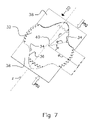
- FIG. 7 is a schematic representation of a gear-cam assembly suitable to practice the invention.
- FIG. 8 illustrates the geometry of the cam follower's contact with the cam plate in the assembly of FIG. 7 .
- FIG. 9 illustrates the forces resulting from the geometry shown in FIG. 8 .
- FIG. 10 illustrates the invention coupling the gear-cam assembly of FIG. 7 with a linear piston.
- FIG. 11 shows the shape of the cam required to counter the conservative force acting on the piston in the arrangement of FIG. 10 .
- FIG. 12 shows the result produced by the cam of FIG. 11 in the arrangement of FIG. 10 .
- FIG. 13 shows the geometry of a typical piston/crankshaft arrangement.
- FIG. 14 illustrates the invention coupling the gear-cam assembly of FIG. 7 with the rotational piston arrangement of FIG. 13 .
- FIG. 15 shows the shape of the cam required to counter the conservative force acting on the piston in the arrangement of FIG. 14 .
- FIG. 16 shows the result produced by the cam of FIG. 15 in the arrangement of FIG. 14 .
- FIG. 17 illustrates the invention coupling-the gear-cam assembly of FIG. 7 with a four-stroke engine.
- FIG. 18 illustrates a magnetostatic application of the invention based on a cylindrical magnet suspended between two fixed plates that define a cavity therebetween.
- FIG. 19 shows a symmetric system wherein a magnet is fitted with two end caps and is constrained to motion in a sealed gas-filled cylinder.
- FIG. 20 shows the result obtained using a magnetostatic counterforce to provide adiabatic pressure compensation with the cam-free system of FIG. 19 .
- FIG. 21 shows the result obtained using a magnetostatic counterforce to provide isothermal pressure compensation with the cam-free system of FIG. 19 .
- FIG. 22 is a perspective view of a cam-based device used to test the concept of the invention.
- FIG. 23 is a top view of the device of FIG. 22 .
- FIG. 24 is an energy-versus-mass plot showing the minimum raw energy required to run the device of FIG. 22 for a single cycle as a function of the mass used in the counterforce mechanism.
- FIG. 25 shows the results of FIG. 24 with the frictional forces eliminated.
- the heart of the invention lies in the realization that the presence of an adjunct conservative force in a reciprocating machine can be used advantageously to reduce the energy required of an inefficient source to drive it.
- a conventional reciprocating heat engine in which conservative forces arise from the displacement of a piston or other equivalently moveable member (such as the rotor of a rotary engine) due to change in volume of the working medium of the engine, this reduction is achieved by coupling a supplemental force to the piston over a range of its motion in such a manner as to counterbalance those forces.
- the counterforce may be viewed as a force that pushes the piston into the cylinder with the identical force as a function of position as the force with which the gas repels the piston out of the cylinder.
- the first referred to herein as “fixed” coupling, is based on the existence of a conservative force mechanism that can produce, over some range of operation, a nearly exact, but oppositely directed, force, as a function of its displacement, as that arising from the volume change of the working medium in response to the displacement of the piston. If such a mechanism can be identified and implemented, then it is possible to couple the position changes of the piston directly to those of the counterforce device and the sum of the forces will equal zero.
- variable coupling uses any convenient device capable of providing a conservative force over a given range of operation of the device such that the total work done by that force over that range is equal to the work done by the piston in compressing the working medium over some appropriate range of its motion.
- the piston must be coupled to the generalized coordinate of the proposed counterforce device in such a way that the infinitesimal work done by the motion of one exactly counters that done by the other over their respective, and corresponding, ranges of motion.
- Such coupling will, in general, involve a variation as a function of position in the mechanical advantage of the counterforce with respect to the pressure force it is to counter.
- Such coupling mechanical advantage is well-known in the art as arising from the general concept of a lever in which a displacement at one end of the coupler corresponds to a different displacement at the other.
- the action of the lever itself can provide some trigonometric variation in the mechanical advantage it affords. Greater variation in the mechanical advantage can be obtained through a “linkage” in which multiple levers are interconnected and the assembly is used as the coupler. Even greater variation is afforded by allowing the members of a linkage to adjust their interconnections as a function of their relative position.
- One implementation of a continuously variable linkage is a cam in which the interconnection is described by the contact point of one linkage member on some geometric surface of another. Without loss of generality, the following will reference “fixed” coupling as “cam-free” and “variable” coupling as “cam-based.”
- Springs wherein forces result from deformation of a material
- the force profile F e (z) of an electrostatic system is inverse quadratic with respect to the separation distance z of the charges, as follows
- F p ⁇ ( z ) k ⁇ ( 1 + z L ) - ⁇ , ( 26 )
- k is a determinable constant
- z indicates a change in the separation distance between a piston and the end of a containing cylinder
- ⁇ is a constant frequently, but not exclusively, related to the ratio of specific heats.
- FIG. 5 A permanent cylindrical magnet 20 of magnetization M along its axis, radius r m , and length l m is suspended a distance d over a ferrous plate, 22 .
- ⁇ M ⁇ ′ M ⁇ ( ⁇ - 1 ) ( ⁇ + 1 ) ⁇ z ⁇ . ( 28 ) is located a distance d below the plane 26 of the ferrous plate 22 ( ⁇ is the relative permeability of the plate). The force between the magnet and the plate is, then, identical to the force between the magnet and its image.
- a cylindrical magnet with uniform magnetization M directed along its axis can be treated as being induced by a surface current of magnitude M about the circumference of the radial boundary of the magnet (see Jackson, supra).
- the magnetic field at a point r generated by the image surface current can be determined from the vector potential given by
- Equation 34 The known solution (see Y. L. Luke, Integrals of Bessel Functions, McGraw-Hill, 1962, pp. 314-318) for the integral in Equation 34 is given by
- Equation 36 provides a rich field of adjustable parameters, making it a candidate for both cam-free and cam-based implementations of the pressure compensation force device of the invention.
- Conceptual implementations of these two general techniques using the forces examined above are disclosed in the section that follow.
- the term “reciprocating” is intended to refer to any mechanism that includes a moveable member that undergoes a periodic motion over a repetitive path the extent of which may vary. In the absence of variation of the path the motion of the moveable member is both periodic and cyclical.
- the term “piston” is used with reference to any moveable member subjected to a reciprocating motion, as defined above.
- Countless cam implementations may be employed to counter the pressure force (and the corresponding torque on an engine's output shaft) described above.
- the following disclosure endeavors to provide details of the procedures required to design suitable candidates.
- a gear-cam assembly 30 consists of a gear 32 with two face-mounted, diametrically opposed cam followers 34 , such that the followers contact the shaped edges 36 of two symmetric plates 38 as the gear 32 rotates.
- the plates 38 are restricted to movement along a single axis, labeled z, parallel to the gear face and are subjected to candidate conservative forces, F(z), along that directions shown in the figure (two forces are shown in the figure, but it is understood that a single force, twice the magnitude, could be used in an equivalent manner).
- F(z) candidate conservative forces
- each follower 34 is given by its distance R from the center 40 of the gear 32 and the rotation angle ⁇ of the gear.
- the working surface of each cam plate 38 is defined by the radius vector p, which is a function of the angle ⁇ .
- the radius of the gear is shown as g.
- FIG. 8 provides a detailed view of the cam-follower/cam-plate contact geometry highlighting the difference between the contact angle, ⁇ , and the follower position angle, ⁇ .
- the candidate counterforce, F(z) is applied to the gear 20 only through its normal component F n at the cam/follower contact point 42 . This normal force F n is also seen in FIG. 8 .
- FIG. 10 shows the configuration of FIG. 10 with the parameters listed in Table 1 below results in the cam shape shown in FIG. 11 .
- FIG. 12 shows the performance of such a cam.
- the horizontal axis is the rotational angle and the vertical axis is the torque on the gear cam.
- the solid line is the torque due to the pressure force
- the dotted line indicates the torque due to the spring
- the dashed line shows the resulting sum.
- the vanishingly small net torque shows that the goal of countering the pressure force has been achieved.
- FIG. 13 illustrates compensation according to the invention in a system comprising a conventional reciprocating piston 50 and a connecting rod 54 hingedly attached to the piston and to the crank 56 of a rotating crankshaft 58 .
- the triangle formed by these elements is represented in the figure by side lengths a, b, and c and angles ⁇ , ⁇ , and ⁇ . Recalling various trigonometric identities, it is possible to derive the following relations:
- ⁇ V 0 A ⁇ ( L + a - b ) ( 48 )
- BDC bottom dead center
- Equation 48 p 0 ⁇ ( V 0 V ) ⁇ , ( 50 ) where the zero subscript identifies some reference volume, temperature, and pressure. Inserting the items of Equation 48 into Equation 50 leads to the following adiabatic relation:
- the torque about the axis of the crankshaft 58 is given by the product of the component of the force of Equation 51 along the connecting rod 54 and the perpendicular distance from this force component and the crankshaft axis. This is given by
- the size/ratio difference in the gears 32 , 60 results in a pressure-sourced torque on the gear-cam gear 32 given by
- Equation 45 ⁇ p 0 ⁇ Aa ⁇ sin ⁇ ( 2 ⁇ ⁇ ) ⁇ ( L - a ⁇ cos ⁇ ( 2 ⁇ ⁇ ⁇ ) - [ b 2 - a 2 ⁇ sin 2 ⁇ ( 2 ⁇ ⁇ ⁇ ) ] 1 2 ( L + a - b ) ) - ⁇ ⁇ ( a ⁇ cos ⁇ ( 2 ⁇ ⁇ ) ⁇ [ b 2 - a 2 ⁇ sin 2 ⁇ ( 2 ⁇ ⁇ ) ] - 1 2 + 1 ) . ( 54 ) If a spring is again used as the example counterforce of the invention, then Equation 45 remains valid. Accordingly, the solution previously used in the linear piston example provides again a reliable template for determining the cam shape in the rotational case.
- two main operating modes are mostly employed in practice. They are normally referred to as the two-cycle and the four-cycle modes.
- the former allows for the intake of the fuel/air mixture and the exhaust of combustion products during the power stroke.
- the latter requires two full translations of the piston for each cycle. Accordingly, pressure compensation of the two-cycle engine may be accomplished as shown in the examples above, since those examples employ a 2 ⁇ cycle protocol.
- a bar 62 is hingedly coupled to a fixed mounting point 64 on the upper cam plate 38 and includes a notch 66 adapted to capture a post 68 on the lower cam plate 38 ′ when the separation distance between the two cam plates is maximum, thereby removing the counterforce from the system.
- One of the cam followers 70 is longer than the other (shown as 70 ′), so that it will contact the lower portion of the bar 62 over a small arc as the follower 70 passes through during the rotation of the gear-cam gear 32 . This frees the cam plates 38 , 38 ′ and reintroduces the counterforce to the system.
- the counterforce Since only one of the two followers can free the cam plates, the counterforce will only be applied over ⁇ radians or, by the analysis above, over every other stroke of the piston. Thus, during the compression and power strokes of the four-cycle engine, the counterforce is active; during the exhaust and intake strokes, it is absent.
- the goal of optimizing the efficiency of a system in which a substance is cyclically compressed may be achieved using any static device capable of conservative-force implementation.
- static forces described above gravitation, spring, electrostatic, magnetostatic, pressure
- magnets are necessarily dipole devices, they lend themselves more readily to applications in which both poles are used. This implies a C2 symmetry of the resulting counterforce mechanism, which, in turn, implies a corresponding symmetry in the heat engine of interest.
- the cylindrical magnet 20 is suspended between two fixed plates 22 and 80 that define a cavity therebetween.
- Plate 22 with relative permeability ⁇ 2 , lies a distance L/2 below the magnet center, as before.
- Plate 80 with relative permeability ⁇ 5 , sits a generally different distance L′/2 above the magnet center.
- the force on the magnet 20 as a function of the magnet's change of its center position, x, can be immediately written as
- the magnet 20 of a symmetric system is fitted with two end caps, 82 and 84 , and constrained to motion in a sealed gas-filled cylinder 86 of length ⁇ .
- the end caps 82 , 84 form a pneumatic seal with the cylinder walls and the ferrous plates provide a small hole through which the gas can pass.
- the pressure will rise in that end and fall in the other, resulting in a restoring pressure-force on the piston.
- the piston will be attracted toward the plate in the direction of travel according to Equation 59.
- the solid trace in FIG. 20 is the resulting magnetic force as a function of piston position.
- the dotted trace is that of the pressure and the dashed trace is the vanishingly small sum of the two, indicating that the goal of countering the pressure forces has been accomplished.
- isothermal operation may be accomplished using a feedback mechanism where the surface area of a heat sink bathed in the gas of the engine is adjusted to maintain a constant gas temperature.
- Two such heat sinks are installed at each end of the engine shown in FIG. 19 , one connected to a cold reservoir and the other connected to a hot one.
- the cold sink in one end of the engine and the hot sink in the other are “disabled” while their companions are “activated.”
- the sinks are disabled and the alternates are activated.
- the internal energy change of the engine is identically zero, thereby meeting the requirement for an isothermal heat engine.
- Cam-free counterforce mechanism implementation using non-magnetostatic forces follows an equivalent technique of design. However, these force profiles differ significantly from that of the magnetostatic arrangement. Therefore, the range of operation over which their unleveraged magnitude is substantially that of the pressure force to be countered may be reduced.
- a cam-based apparatus was used. As shown in FIG. 22 , such a counterforce mechanism 90 included a double-acting cylinder 92 with a piston (not seen) rigidly attached to a cam assembly 94 via a connecting rod 96 . As the piston moves within the cylinder 92 , the cam translates along a similar linear path while a lever arm 98 tracks along the shaped surface of a cam plate (not shown).
- a counterpart lever arm 100 mounted on the same shaft, rides along a parallel rail arrangement 102 .
- the parallel rails approach one another allowing a cable 104 to extend around an idler roller 106 .
- a mass-attachment bar 108 is attached to the end of the cable 104 .
- FIG. 23 is a more detailed, top view of the counterforce mechanism 90 showing the lever-arm-mounted cam followers 110 , 112 and the cam shape itself (normally obscured by the lever arms).
- the shape of the cam is designed in a manner similar to the technique described earlier for gear-cam design.
- FIGS. 24 and 25 illustrate the results of the experiment.
- FIG. 24 identifies the minimum raw energy required to run the apparatus 90 for a single cycle as a function of the mass used in the counterforce mechanism. That is, for each weight attached to the bar 108 , the energy required by the motor 114 to operate the mechanism at a predetermined speed [ft7] was measured. Clearly, this energy included a portion needed to overcome the frictional forces of the system, which are not part of the conservative forces that are the focus of the invention.
- FIG. 25 shows the results of the experiment with the frictional forces eliminated. This was accomplished by first determining the energy required to operate the device with the double-acting cylinder unsealed, thereby eliminating all compression forces while still monitoring the energy required to overcome frictional forces. The result of this test found that 0.492 J was required to overcome the friction of the device over one cycle. Zero counterforce mass was used in the compression-less operation, so the counterforce-mechanism friction was not determined in that test. To make that determination, the device was operated using the minimum mass that still allowed the counterforce mechanism to operate. The difference between this and the energy required to operate the device with zero counterforce mass was then identified as the counterforce-mechanism friction. This was found to be 0.136 J per cycle.
Priority Applications (4)
| Application Number | Priority Date | Filing Date | Title |
|---|---|---|---|
| US11/129,783 US7441530B2 (en) | 2004-12-13 | 2005-05-16 | Optimal heat engine |
| PCT/US2005/042667 WO2006065489A2 (fr) | 2004-12-13 | 2005-11-23 | Moteur thermique optimal |
| CN2005800478915A CN101142384B (zh) | 2004-12-13 | 2005-11-23 | 最佳热机 |
| US11/807,065 US7610894B2 (en) | 2005-05-16 | 2007-05-25 | Self-compensating cylinder system in a process cycle |
Applications Claiming Priority (2)
| Application Number | Priority Date | Filing Date | Title |
|---|---|---|---|
| US63559304P | 2004-12-13 | 2004-12-13 | |
| US11/129,783 US7441530B2 (en) | 2004-12-13 | 2005-05-16 | Optimal heat engine |
Related Child Applications (1)
| Application Number | Title | Priority Date | Filing Date |
|---|---|---|---|
| US11/807,065 Continuation-In-Part US7610894B2 (en) | 2005-05-16 | 2007-05-25 | Self-compensating cylinder system in a process cycle |
Publications (2)
| Publication Number | Publication Date |
|---|---|
| US20060124100A1 US20060124100A1 (en) | 2006-06-15 |
| US7441530B2 true US7441530B2 (en) | 2008-10-28 |
Family
ID=36582351
Family Applications (1)
| Application Number | Title | Priority Date | Filing Date |
|---|---|---|---|
| US11/129,783 Expired - Fee Related US7441530B2 (en) | 2004-12-13 | 2005-05-16 | Optimal heat engine |
Country Status (3)
| Country | Link |
|---|---|
| US (1) | US7441530B2 (fr) |
| CN (1) | CN101142384B (fr) |
| WO (1) | WO2006065489A2 (fr) |
Cited By (4)
| Publication number | Priority date | Publication date | Assignee | Title |
|---|---|---|---|---|
| US20090247360A1 (en) * | 2008-03-26 | 2009-10-01 | Morris Ben-Shabat | Linear Engine |
| US20110048382A1 (en) * | 2009-08-25 | 2011-03-03 | Manousos Pattakos | Rack gear variable compression ratio engines |
| US20110283969A1 (en) * | 2010-05-19 | 2011-11-24 | Mce-5 Development | Elastic fixing for a piston of a variable compression ratio engine |
| US11078835B2 (en) * | 2016-05-24 | 2021-08-03 | MCE 5 Development | Bearing guide device of a combustion piston for a variable compression ratio engine |
Families Citing this family (1)
| Publication number | Priority date | Publication date | Assignee | Title |
|---|---|---|---|---|
| US20070283908A1 (en) * | 2006-06-07 | 2007-12-13 | Kwong Wang Tse | Tse's internal combustion engine |
Citations (8)
| Publication number | Priority date | Publication date | Assignee | Title |
|---|---|---|---|---|
| US4319546A (en) * | 1980-04-18 | 1982-03-16 | Beden Moses M | Hydraulic combustion engine |
| US4938192A (en) * | 1989-05-02 | 1990-07-03 | Pavo Pusic | Piston cylinder combination with engine cylinder wall having valve ports and combustion chamber |
| US5755195A (en) * | 1996-03-11 | 1998-05-26 | Dawson; Lyle E. | Internal combustion engine with a gear arrangement on a connection between the piston and the crankshaft and a method of operation thereof |
| US20020073954A1 (en) * | 2000-06-15 | 2002-06-20 | Han Xiao-Jing | Two-stroke engine |
| US6453869B1 (en) * | 2001-01-04 | 2002-09-24 | Mooremac, Llc | Internal combustion engine with variable ratio crankshaft assembly |
| US6564762B2 (en) * | 2000-04-28 | 2003-05-20 | Glendal R. Dow | Gear train crankshaft |
| US6701885B2 (en) * | 2002-05-13 | 2004-03-09 | General Motors Corporation | Engine connecting rod mechanism for cylinder pressure control |
| US6857412B2 (en) * | 2001-01-24 | 2005-02-22 | Hasan Basri Ozdamar | Motor with rotary connecting rod bolt |
-
2005
- 2005-05-16 US US11/129,783 patent/US7441530B2/en not_active Expired - Fee Related
- 2005-11-23 CN CN2005800478915A patent/CN101142384B/zh not_active Expired - Fee Related
- 2005-11-23 WO PCT/US2005/042667 patent/WO2006065489A2/fr active Application Filing
Patent Citations (9)
| Publication number | Priority date | Publication date | Assignee | Title |
|---|---|---|---|---|
| US4319546A (en) * | 1980-04-18 | 1982-03-16 | Beden Moses M | Hydraulic combustion engine |
| US4938192A (en) * | 1989-05-02 | 1990-07-03 | Pavo Pusic | Piston cylinder combination with engine cylinder wall having valve ports and combustion chamber |
| US5755195A (en) * | 1996-03-11 | 1998-05-26 | Dawson; Lyle E. | Internal combustion engine with a gear arrangement on a connection between the piston and the crankshaft and a method of operation thereof |
| US6564762B2 (en) * | 2000-04-28 | 2003-05-20 | Glendal R. Dow | Gear train crankshaft |
| US20020073954A1 (en) * | 2000-06-15 | 2002-06-20 | Han Xiao-Jing | Two-stroke engine |
| US6453869B1 (en) * | 2001-01-04 | 2002-09-24 | Mooremac, Llc | Internal combustion engine with variable ratio crankshaft assembly |
| US6857412B2 (en) * | 2001-01-24 | 2005-02-22 | Hasan Basri Ozdamar | Motor with rotary connecting rod bolt |
| US6990944B2 (en) * | 2001-01-24 | 2006-01-31 | Hasan Basri Ozdamar | Motor with rotary connecting rod bolt |
| US6701885B2 (en) * | 2002-05-13 | 2004-03-09 | General Motors Corporation | Engine connecting rod mechanism for cylinder pressure control |
Cited By (7)
| Publication number | Priority date | Publication date | Assignee | Title |
|---|---|---|---|---|
| US20090247360A1 (en) * | 2008-03-26 | 2009-10-01 | Morris Ben-Shabat | Linear Engine |
| US20110048382A1 (en) * | 2009-08-25 | 2011-03-03 | Manousos Pattakos | Rack gear variable compression ratio engines |
| US8220422B2 (en) * | 2009-08-25 | 2012-07-17 | Manousos Pattakos | Rack gear variable compression ratio engines |
| US20110283969A1 (en) * | 2010-05-19 | 2011-11-24 | Mce-5 Development | Elastic fixing for a piston of a variable compression ratio engine |
| US8662050B2 (en) * | 2010-05-19 | 2014-03-04 | MCE 5 Development | Elastic fixing for a piston of a variable compression ratio engine |
| AU2011254465B2 (en) * | 2010-05-19 | 2015-01-22 | Mce-5 Development | Elastic fixing element for a piston of a variable compression ratio engine |
| US11078835B2 (en) * | 2016-05-24 | 2021-08-03 | MCE 5 Development | Bearing guide device of a combustion piston for a variable compression ratio engine |
Also Published As
| Publication number | Publication date |
|---|---|
| CN101142384B (zh) | 2010-06-16 |
| WO2006065489A2 (fr) | 2006-06-22 |
| CN101142384A (zh) | 2008-03-12 |
| US20060124100A1 (en) | 2006-06-15 |
| WO2006065489A3 (fr) | 2007-11-22 |
Similar Documents
| Publication | Publication Date | Title |
|---|---|---|
| JP6790027B2 (ja) | 高効率線形燃焼機関 | |
| Atkinson et al. | Numerical simulation of a two-stroke linear engine-alternator combination | |
| Hung et al. | A review of free-piston linear engines | |
| US8997699B2 (en) | Linear free piston combustion engine with indirect work extraction via gas linkage | |
| US7441530B2 (en) | Optimal heat engine | |
| US20120126544A1 (en) | High-efficiency two-piston linear combustion engine | |
| Guo et al. | Research on the operation characteristics of a free-piston linear generator: Numerical model and experimental results | |
| WO2007059565A1 (fr) | Moteur a pistons libres a quatre temps | |
| US20120126543A1 (en) | High-efficiency single-piston linear combustion engine | |
| PL177464B1 (pl) | Mechanizm korbowo-wodzikowy do przekształcania prostoliniowego ruchu posuwisto-zwrotnego w ruch obrotowy, zwłaszcza do endotermicznych silników tłokowych | |
| Hanipah | Development of a spark ignition free-piston engine generator | |
| Bade et al. | Piston rings friction comparison in a free piston and conventional crankshaft engines | |
| US7610894B2 (en) | Self-compensating cylinder system in a process cycle | |
| JP3367507B2 (ja) | フリーピストン形スターリングエンジン | |
| Fukui et al. | Study on high specific power micro-Stirling engine | |
| US8381699B2 (en) | Engine crankshaft and method of use | |
| Xu et al. | Modelling and control of an internal combustion linear generator integrated power system | |
| Hanipah et al. | A New Piston Referencing Algorithm for Qualitative Assessment of Free-Piston Engine Generator Performance | |
| Nerubenko et al. | Hybrid Linear Generator | |
| Mohammed et al. | Effect of generator configuration on the free-piston motion and power generation of air-driven expander system | |
| Hong et al. | Preliminary Analysis of a Long Stroke Natural Gas Engine Based on LSRM | |
| TW219968B (en) | Improved internal combustion engine | |
| WO2011068258A1 (fr) | Procédé de commande d'un moteur à piston libre utilisant une courbe prédictive et moteur à piston libre commandé par ce procédé | |
| CN117167138A (zh) | 一种滑膛式季差绝热内燃机 | |
| KAREEM | WASIU B. AYANDOTUN1, 2, RASHID BA AZIZ2 |
Legal Events
| Date | Code | Title | Description |
|---|---|---|---|
| AS | Assignment |
Owner name: FSNC, LLC, ARIZONA Free format text: ASSIGNMENT OF ASSIGNORS INTEREST;ASSIGNOR:TINKER, MR. FRANK A.;REEL/FRAME:016580/0415 Effective date: 20050921 |
|
| STCF | Information on status: patent grant |
Free format text: PATENTED CASE |
|
| FPAY | Fee payment |
Year of fee payment: 4 |
|
| FEPP | Fee payment procedure |
Free format text: PATENT HOLDER CLAIMS MICRO ENTITY STATUS, ENTITY STATUS SET TO MICRO (ORIGINAL EVENT CODE: STOM); ENTITY STATUS OF PATENT OWNER: MICROENTITY |
|
| FPAY | Fee payment |
Year of fee payment: 8 |
|
| FEPP | Fee payment procedure |
Free format text: MAINTENANCE FEE REMINDER MAILED (ORIGINAL EVENT CODE: REM.); ENTITY STATUS OF PATENT OWNER: MICROENTITY |
|
| LAPS | Lapse for failure to pay maintenance fees |
Free format text: PATENT EXPIRED FOR FAILURE TO PAY MAINTENANCE FEES (ORIGINAL EVENT CODE: EXP.); ENTITY STATUS OF PATENT OWNER: MICROENTITY |
|
| STCH | Information on status: patent discontinuation |
Free format text: PATENT EXPIRED DUE TO NONPAYMENT OF MAINTENANCE FEES UNDER 37 CFR 1.362 |
|
| FP | Lapsed due to failure to pay maintenance fee |
Effective date: 20201028 |