US7441257B2 - Method and apparatus for cooling a compact disc - Google Patents
Method and apparatus for cooling a compact disc Download PDFInfo
- Publication number
- US7441257B2 US7441257B2 US10/797,417 US79741704A US7441257B2 US 7441257 B2 US7441257 B2 US 7441257B2 US 79741704 A US79741704 A US 79741704A US 7441257 B2 US7441257 B2 US 7441257B2
- Authority
- US
- United States
- Prior art keywords
- compact disc
- hub
- fan
- fan device
- propellers
- Prior art date
- Legal status (The legal status is an assumption and is not a legal conclusion. Google has not performed a legal analysis and makes no representation as to the accuracy of the status listed.)
- Expired - Lifetime, expires
Links
Images


Classifications
-
- G—PHYSICS
- G11—INFORMATION STORAGE
- G11B—INFORMATION STORAGE BASED ON RELATIVE MOVEMENT BETWEEN RECORD CARRIER AND TRANSDUCER
- G11B17/00—Guiding record carriers not specifically of filamentary or web form, or of supports therefor
- G11B17/02—Details
- G11B17/022—Positioning or locking of single discs
- G11B17/028—Positioning or locking of single discs of discs rotating during transducing operation
- G11B17/0282—Positioning or locking of single discs of discs rotating during transducing operation by means provided on the turntable
-
- G—PHYSICS
- G11—INFORMATION STORAGE
- G11B—INFORMATION STORAGE BASED ON RELATIVE MOVEMENT BETWEEN RECORD CARRIER AND TRANSDUCER
- G11B33/00—Constructional parts, details or accessories not provided for in the other groups of this subclass
- G11B33/14—Reducing influence of physical parameters, e.g. temperature change, moisture, dust
- G11B33/1406—Reducing the influence of the temperature
- G11B33/1413—Reducing the influence of the temperature by fluid cooling
- G11B33/142—Reducing the influence of the temperature by fluid cooling by air cooling
Definitions
- This invention relates generally to compact discs, and, more particularly, to a machine for reading or writing to a compact disc.
- a compact disc player tends to heat up, i.e., raise the temperature of, a compact disc that it plays, mostly due to the heat produced by the high power electronics in the compact disc player. Heating of a compact disc is considered undesirable because a hot disc is unpleasant to the touch, and because a consumer may fear that the compact disc will become warped or otherwise damaged from the heat.
- a device for cooling a compact disc before the disc is ejected from the player is a device for cooling a compact disc before the disc is ejected from the player.
- Adding a motor and a fan to the compact disc player is not a desirable solution to the problem of cooling a compact disc.
- the only location in the player in which it may be practical to add a motor and a fan is at the rear or side of the player's housing. These locations are not ideal for the cooling of the surface of the compact disc.
- motors and cooling fans that are typically used in compact disc players and radios are comparatively expensive.
- the additional power draw of the fan motor may require a more expensive or larger power supply.
- motors and fans mounted on the chassis of a radio or compact disc player can become acoustically noisy, i.e., create an unpleasant audible sound, as well as electrically noisy, i.e., create undesirable magnetic fields resulting in electromagnetic interference (EMI).
- EMI electromagnetic interference
- the present invention provides a fan in the form of a plurality of propellers that are attached to the hub of the compact disc player. During reading of the compact disc, the propellers rotate along with the hub, thereby cooling the compact disc by either blowing air toward or drawing air away from the compact disc.
- an apparatus for cooling a compact disc includes an actuator for rotating the compact disc.
- An air-moving device is driven by the actuator and moves air about the compact disc.
- an apparatus for cooling a compact disc includes a hub retaining the compact disc. At least one propeller is attached to the hub. An actuator is coupled to the hub and rotates the hub such that the at least one propeller moves air about the compact disc.
- a method for processing a compact disc includes placing the compact disc on a rotatable hub such that a throughhole of the compact disc receives the hub.
- the compact disc is engaged with a fan device such that the compact disc is biased farther onto the hub.
- the fan device is attached to the hub.
- the hub is rotated such that the compact disc and the fan device also rotate, and the fan device moves air about the compact disc to thereby carry heat away from the compact disc.
- An advantage of the present invention is that an additional motor is not required in order to operate the fan.
- Another advantage is that the fan does not draw additional power, and no modification of the power supply is needed.
- Yet another advantage is that the fan does not create additional acoustic or electrical noise.
- FIG. 1 is a schematic side view of a compact disc player including one embodiment of a compact disc cooling apparatus of the present invention.
- FIG. 2 is a top view of one embodiment of the air-moving device of the cooling apparatus of FIG. 1 .
- FIG. 3 is a schematic side view of another compact disc player including another embodiment of a compact disc cooling apparatus of the present invention.
- FIG. 4 is a flow chart of one embodiment of a method of the present invention for processing a compact disc.
- FIG. 5 is a schematic side view of yet another compact disc player including yet another embodiment of a compact disc cooling apparatus of the present invention.
- FIG. 6 is a schematic side view of a further compact disc player including a further embodiment of a compact disc cooling apparatus of the present invention.
- FIG. 7 is a schematic side view illustrating the angular relationship between one embodiment of a propeller of an air-moving device of a compact disc cooling apparatus of the present invention and a plane defined by the compact disc.
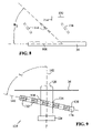
- FIG. 8 is a schematic side view illustrating the angular relationship between another embodiment of a propeller of an air-moving device of a compact disc cooling apparatus of the present invention and a plane defined by the compact disc.
- FIG. 9 is a schematic side view illustrating the angular relationship between a plane defined by a further embodiment of an air-moving device of a compact disc cooling apparatus of the present invention and an axis of rotation of a hub of the compact disc player.
- Cooling apparatus 14 includes an actuator in the form of a motor 16 coupled to a hub 18 .
- An air-moving device in the form of a fan 20 is also coupled to or otherwise attached to hub 18 .
- Hub 18 can be substantially cylindrically shaped with a slight taper such that the width or diameter 22 of hub 18 increases slightly in direction 24 .
- Fan 20 can be a closed ring type of fan including propellers 26 ( FIG. 2 ) interconnecting an outer closed ring 28 and an inner closed ring 30 that defines a circular throughhole 32 . Conversely, rings 28 , 30 connect propellers 26 together.
- fan 20 When cooling apparatus 14 is assembled, fan 20 is placed on hub 18 such that throughhole 32 receives hub 18 with a friction fit. More particularly, fan 20 is placed on hub 18 such that ring 30 slides along hub 18 in direction 24 until the increasing diameter of hub 18 matches the diameter of throughhole 32 . Due to the friction between ring 30 and hub 18 , fan 20 is thus snugly attached to hub 18 with propellers 26 extending in a radial direction from hub 18 .
- player 10 places compact disc 34 on hub 18 in a manner similar to how fan 20 is placed on hub 18 .
- Compact disc 34 also includes a central throughhole (not shown) for receiving hub 18 as is well known in the art.
- motor 16 rotates hub 18 at a speed approximately between 230 and 27,900 revolutions per minute. It is possible for motor 16 to rotate hub 18 in either direction, i.e., clockwise or counterclockwise. Both fan 20 and compact disc 34 rotate along with hub 18 by virtue of being attached thereto by a friction fit.
- the rotation of fan 20 can causes propellers 26 to blow air in direction 36 toward a label-side 38 of compact disc 34 , i.e., toward a side of compact disk 34 opposite read head 12 .
- fan 20 can be configured such that propellers 26 draw air in direction 24 away from label-side 38 . Regardless of whether fan 20 moves air in direction 36 or in direction 24 , the moving air removes heat from label-side 38 of compact disc 34 via convection.
- read head 12 reads information from a read side 40 of compact disc 34 in a manner well known in the art.
- An arm-like mechanism (not shown) can move read head 12 in the directions indicated by double arrow 42 in order that head 12 can read all information dispersed between the central throughhole and outer edge 44 of read side 40 .
- Cooling apparatus 54 includes an actuator in the form of a motor 56 coupled to a hub 58 .
- An air-moving device in the form of a fan 60 is also coupled to or otherwise attached to hub 58 .
- a compression arm 61 is integrally formed with fan 60 . That is, compression arm 61 and fan 60 together form a monolithic structure.
- a compression arm is generally known in the art as a device that pushes a compact disc onto a hub such that a throughhole of the compact disc receives the hub with a friction fit.
- Hub 58 can be substantially cylindrically shaped with a slight taper such that the width or diameter 62 of hub 58 increases slightly in direction 24 .
- Fan 60 can be a closed ring type of fan similar to fan 20 , including propellers, an outer closed ring and an inner closed ring.
- a consumer inserts a compact disc 34 into player 50 , and player 50 places compact disc 34 on hub 58 such that a central throughhole (not shown) of compact disc 34 receives hub 58 (step S 402 ).
- Player 50 then engages compact disc 34 with fan 60 such that compact disc 34 is biased farther onto hub 58 (step S 404 ) in direction 24 .
- player 50 uses compression arm 61 to push fan 60 into engagement with compact disc 34 until disc 34 is attached to hub 58 with a friction fit.
- Fan 60 may include one or more optional projections 64 for engaging and pushing fan in direction 24 while maintaining a gap 66 between the propellers of fan 60 and compact disc 34 .
- fan 60 is attached to hub 58 (step S 406 ).
- player 50 uses compression arm 61 to push fan 60 onto hub 58 until fan 60 is attached to hub 58 with a friction fit. It is possible for compression arm 61 to pull fan 60 back in direction 36 to thereby create gap 66 after fan 60 has pushed compact disc 34 into its proper place. Gap 66 may be small enough that fan 60 is still attached to hub 58 with a friction fit after being pulled back in direction 36 by compression arm 61 to create gap 66 .
- hub 58 is rotated such that compact disc 34 and fan 60 also rotate, and fan 60 moves air about compact disc 34 to thereby carry heat away from compact disc 34 (step S 408 ).
- motor 56 rotates hub 58 , compact disc 34 and fan 60 such that fan 60 blows air in direction 24 toward label-side 38 of compact disc 34 .
- fan 60 can be configured such that its propellers draw air in direction 36 away from label-side 38 . Regardless of whether fan 60 moves air in direction 36 or in direction 24 , the moving air removes heat from label-side 38 of compact disc 34 via convection.
- read head 52 reads information from a read side 40 of compact disc 34 in a manner well known in the art.
- An arm-like mechanism (not shown) can move read head 52 in the directions indicated by double arrow 42 in order that head 52 can read all information dispersed between the central throughhole and outer edge 44 of read side 40 .
- Other aspects of compact disc player 50 are substantially similar to those of compact disc player 10 , and thus are not discussed in detail herein.
- Cooling apparatus 74 includes an actuator in the form of a motor 76 coupled to a hub 78 .
- An air-moving device in the form of a fan 80 is also coupled to or otherwise attached to hub 78 .
- read head 72 and fan 80 are on the same side of compact disc 34 in player 70 .
- the propellers of fan 80 move air adjacent a read side 40 of compact disc 34 rather than adjacent a label-side 38 as in players 10 , 50 .
- Fan 80 is provided with a diameter 82 that is smaller than the diameter of fan 20 in order to avoid fan 80 interfering with read head 72 . More particularly, a radially outermost tip 84 of a propeller of fan 80 is closer to hub 78 in radial direction 42 than is read head 72 . Further, as head 72 moves in radial directions 42 to read disc 34 , it is possible to prevent read head 72 from moving any closer to hub 78 than is outermost tip 84 . This restriction of the movement of head 72 can be achieved either mechanically or via software.
- Other aspects of compact disc player 70 are substantially similar to those of compact disc player 10 , and thus are not discussed in detail herein.
- Cooling apparatus 94 includes an actuator in the form of a motor 96 coupled to a hub 98 .
- player 90 includes an air-moving device in the form of a fan 100 that is coupled to or otherwise attached to motor 96 rather than to hub 98 .
- fan 100 is not on the same vertical level as read head 92 , as can be clearly seen in FIG. 6 .
- fan 100 does not restrict or limit the movement of read bead 92 in directions 42 .
- fan 100 may be provided with a diameter that is smaller than the diameter of fan 20 in order that the area of strongest air movement is limited to the area closely adjacent hub 98 .
- the reduced diameter of fan 100 can inhibit the air that is moved by fan 100 from disturbing the movement or operation of read head 92 .
- Other aspects of compact disc player 90 are substantially similar to those of compact disc player 10 , and thus are not discussed in detail herein.
- FIGS. 7 and 8 illustrate how the pitch of the propeller blades in conjunction with the direction of rotation of the fan determines whether the fan will blow air toward compact disc 34 or draw air away from compact disc 34 . More particularly, each of propeller blades 106 in FIG. 7 has a pitch angle ⁇ 1 of approximately 40° relative to a plane 108 defined by compact disk 34 . It should be noted that only the outermost tips of blades 106 , 116 are presented in FIGS. 7 and 8 , and that only the middle one of the three blades 106 , 116 in each figure is presented in a “straight-on” view.
- Each of propeller blades 116 in FIG. 8 has a pitch angle ⁇ 2 of approximately 40° relative to a plane 108 defined by compact disk 34 .
- the direction of the pitch of blades 116 is opposite to the direction of the pitch of blades 106 .
- blades 116 move air in direction 114 away from compact disc 34 . Regardless of whether air is moved in direction 112 or direction 114 , the moving air adjacent compact disk 34 carries heat away from disk 34 by convection.
- Cooling apparatus 124 includes an actuator in the form of a motor 126 coupled to a hub 128 .
- An air-moving device in the form of a fan 130 is also coupled to or otherwise attached to hub 128 .
- fan 130 is neither parallel to compact disc 34 nor perpendicular to hub 128 .
- Fan 130 can be a closed ring type of fan including propellers 132 interconnecting an outer closed ring 134 and an inner closed ring 136 that defines an elliptical throughhole 138 .
- Propellers 132 define a plane 140 that is nonperpendicular to a rotational axis 142 of hub 128 . More particularly, a camber angle between plane 140 and axis 142 is approximately between 60° and 89°.
- both fan 130 and compact disc 34 rotate along with hub 128 by virtue of being attached thereto by a friction fit.
- the rotation of fan 130 causes propellers 132 to blow air in directions that are dependent upon the design of propellers 132 .
- Propellers 132 can be provided with a variety of designs depending upon the requirements of a particular application.
- Other aspects of compact disc cooling apparatus 124 are substantially similar to those of compact disc cooling apparatus 14 , and thus are not discussed in detail herein.
Landscapes
- Cooling Or The Like Of Electrical Apparatus (AREA)
- Structures Of Non-Positive Displacement Pumps (AREA)
Abstract
Description
Claims (12)
Priority Applications (1)
| Application Number | Priority Date | Filing Date | Title |
|---|---|---|---|
| US10/797,417 US7441257B2 (en) | 2004-03-10 | 2004-03-10 | Method and apparatus for cooling a compact disc |
Applications Claiming Priority (1)
| Application Number | Priority Date | Filing Date | Title |
|---|---|---|---|
| US10/797,417 US7441257B2 (en) | 2004-03-10 | 2004-03-10 | Method and apparatus for cooling a compact disc |
Publications (2)
| Publication Number | Publication Date |
|---|---|
| US20050204376A1 US20050204376A1 (en) | 2005-09-15 |
| US7441257B2 true US7441257B2 (en) | 2008-10-21 |
Family
ID=34920048
Family Applications (1)
| Application Number | Title | Priority Date | Filing Date |
|---|---|---|---|
| US10/797,417 Expired - Lifetime US7441257B2 (en) | 2004-03-10 | 2004-03-10 | Method and apparatus for cooling a compact disc |
Country Status (1)
| Country | Link |
|---|---|
| US (1) | US7441257B2 (en) |
Cited By (1)
| Publication number | Priority date | Publication date | Assignee | Title |
|---|---|---|---|---|
| US20230262925A1 (en) * | 2020-10-15 | 2023-08-17 | Nvidia Corporation | Adjustable fan for datacenter cooling systems |
Citations (12)
| Publication number | Priority date | Publication date | Assignee | Title |
|---|---|---|---|---|
| US4823337A (en) * | 1987-04-08 | 1989-04-18 | U.S. Philips Corp. | Device for recording information on or reading information from an information disc |
| JPH01171144A (en) * | 1987-12-25 | 1989-07-06 | Ricoh Co Ltd | Magneto-optical recording/reproducing device |
| JPH03127395A (en) * | 1989-10-13 | 1991-05-30 | Hitachi Ltd | Disc recording and playback device |
| JPH0461686A (en) * | 1990-06-28 | 1992-02-27 | Canon Inc | Optical information recording and reproducing device |
| JPH08279242A (en) * | 1995-03-31 | 1996-10-22 | Sony Corp | Recording and / or reproducing apparatus motor and spindle motor |
| US5793740A (en) * | 1996-12-31 | 1998-08-11 | Compaq Computer Corporation | CD ROM drive apparatus with integral forced air cooling capability |
| US5799006A (en) * | 1992-01-24 | 1998-08-25 | Sony Corporation | Disc table for disc recording/reproducing apparatus and method for producing same |
| JPH10275458A (en) * | 1997-04-01 | 1998-10-13 | Sony Corp | Optical disk and optical disk reproducing and / or recording device |
| JP2001023365A (en) * | 1999-07-09 | 2001-01-26 | Hitachi Ltd | Cooling system |
| US20010015951A1 (en) * | 2000-02-22 | 2001-08-23 | Keiichi Yabushita | Disk clamping mechanism |
| US6699013B2 (en) * | 2002-05-31 | 2004-03-02 | Quantum Corporation | Forced air cooling fan having pivotal fan blades for unidirectional air flow |
| US20050216926A1 (en) * | 2004-03-23 | 2005-09-29 | Lite-On It Corporation | Cooling device used in an optical recording and/or reproducing apparatus |
-
2004
- 2004-03-10 US US10/797,417 patent/US7441257B2/en not_active Expired - Lifetime
Patent Citations (12)
| Publication number | Priority date | Publication date | Assignee | Title |
|---|---|---|---|---|
| US4823337A (en) * | 1987-04-08 | 1989-04-18 | U.S. Philips Corp. | Device for recording information on or reading information from an information disc |
| JPH01171144A (en) * | 1987-12-25 | 1989-07-06 | Ricoh Co Ltd | Magneto-optical recording/reproducing device |
| JPH03127395A (en) * | 1989-10-13 | 1991-05-30 | Hitachi Ltd | Disc recording and playback device |
| JPH0461686A (en) * | 1990-06-28 | 1992-02-27 | Canon Inc | Optical information recording and reproducing device |
| US5799006A (en) * | 1992-01-24 | 1998-08-25 | Sony Corporation | Disc table for disc recording/reproducing apparatus and method for producing same |
| JPH08279242A (en) * | 1995-03-31 | 1996-10-22 | Sony Corp | Recording and / or reproducing apparatus motor and spindle motor |
| US5793740A (en) * | 1996-12-31 | 1998-08-11 | Compaq Computer Corporation | CD ROM drive apparatus with integral forced air cooling capability |
| JPH10275458A (en) * | 1997-04-01 | 1998-10-13 | Sony Corp | Optical disk and optical disk reproducing and / or recording device |
| JP2001023365A (en) * | 1999-07-09 | 2001-01-26 | Hitachi Ltd | Cooling system |
| US20010015951A1 (en) * | 2000-02-22 | 2001-08-23 | Keiichi Yabushita | Disk clamping mechanism |
| US6699013B2 (en) * | 2002-05-31 | 2004-03-02 | Quantum Corporation | Forced air cooling fan having pivotal fan blades for unidirectional air flow |
| US20050216926A1 (en) * | 2004-03-23 | 2005-09-29 | Lite-On It Corporation | Cooling device used in an optical recording and/or reproducing apparatus |
Non-Patent Citations (3)
| Title |
|---|
| Machine translation and English abstract of JP 08279242 A. * |
| Machine translation of JP 2001023365 A. * |
| Official English translation of JP 01-171144. * |
Cited By (2)
| Publication number | Priority date | Publication date | Assignee | Title |
|---|---|---|---|---|
| US20230262925A1 (en) * | 2020-10-15 | 2023-08-17 | Nvidia Corporation | Adjustable fan for datacenter cooling systems |
| US12022634B2 (en) * | 2020-10-15 | 2024-06-25 | Nvidia Corporation | Adjustable fan for datacenter cooling systems |
Also Published As
| Publication number | Publication date |
|---|---|
| US20050204376A1 (en) | 2005-09-15 |
Similar Documents
| Publication | Publication Date | Title |
|---|---|---|
| US6876514B1 (en) | Disk drive including an airflow diverter element radially between spindle motor axis of rotation and cavity in shroud surface | |
| US7224551B1 (en) | Disk drive having apertures aligned near the inner diameter of a disk stack for allowing airflow to pass through the apertures to reduce disk flutter | |
| US6922308B1 (en) | Disk drive comprising a cover shaped to improve radial and axial shrouding | |
| KR100296474B1 (en) | Apparatus and method for improving cooling of coils for voice coil motors in hard disks | |
| US7054103B2 (en) | Downstream finned stripper shroud airstream conditioning apparatus for a disc drive | |
| US6462901B1 (en) | Ribbed shrouding spacer and method for reducing flutter and windage losses in disc drives | |
| US7677805B2 (en) | Fluid dynamic bearing and hard disk drive employing the same | |
| US20050190488A1 (en) | Data recording disk drive with nonplanar plate surfaces for damping out-of-plane disk vibration | |
| JP2003513393A (en) | Actuator arm with tapered trailing edge and embedded head conductor | |
| US6674609B2 (en) | Anechoic chamber noise reduction for a disc drive | |
| US7334243B2 (en) | Vane integration into motor hub to enhance CD cooling | |
| US7441257B2 (en) | Method and apparatus for cooling a compact disc | |
| CN1767041A (en) | Disk drive device | |
| KR100699885B1 (en) | Hard disk drive | |
| JP4094741B2 (en) | Spindle motor | |
| CN1288635C (en) | Disc separator plate with air dam | |
| US8929025B2 (en) | Clamping device for a rotatable component of a machine including a balance hole configured to confine a counterweight | |
| JPH0431697A (en) | Axial blower blade structure | |
| KR100518823B1 (en) | Heat radiating apparatus of optical disk drive | |
| JP2001325785A (en) | Storage device | |
| US20060218564A1 (en) | Optical disk apparatus | |
| JP4207290B2 (en) | Tape drive device | |
| US6456581B1 (en) | Disk player of simplified heat-dissipating structure | |
| JP2001238383A (en) | Motor and disc device equipped with motor | |
| US20080155578A1 (en) | Optical Disk Drive Unit Having a Cooling Device |
Legal Events
| Date | Code | Title | Description |
|---|---|---|---|
| AS | Assignment |
Owner name: DELPHI TECHNOLOGIES, INC., MICHIGAN Free format text: ASSIGNMENT OF ASSIGNORS INTEREST;ASSIGNOR:HJELMELAND, ROBERT W.;REEL/FRAME:015072/0534 Effective date: 20040224 |
|
| STCF | Information on status: patent grant |
Free format text: PATENTED CASE |
|
| FPAY | Fee payment |
Year of fee payment: 4 |
|
| FPAY | Fee payment |
Year of fee payment: 8 |
|
| AS | Assignment |
Owner name: APTIV TECHNOLOGIES LIMITED, BARBADOS Free format text: ASSIGNMENT OF ASSIGNORS INTEREST;ASSIGNOR:DELPHI TECHNOLOGIES INC.;REEL/FRAME:047143/0874 Effective date: 20180101 |
|
| MAFP | Maintenance fee payment |
Free format text: PAYMENT OF MAINTENANCE FEE, 12TH YEAR, LARGE ENTITY (ORIGINAL EVENT CODE: M1553); ENTITY STATUS OF PATENT OWNER: LARGE ENTITY Year of fee payment: 12 |
|
| AS | Assignment |
Owner name: APTIV TECHNOLOGIES (2) S.A R.L., LUXEMBOURG Free format text: ENTITY CONVERSION;ASSIGNOR:APTIV TECHNOLOGIES LIMITED;REEL/FRAME:066746/0001 Effective date: 20230818 Owner name: APTIV MANUFACTURING MANAGEMENT SERVICES S.A R.L., LUXEMBOURG Free format text: MERGER;ASSIGNOR:APTIV TECHNOLOGIES (2) S.A R.L.;REEL/FRAME:066566/0173 Effective date: 20231005 Owner name: APTIV TECHNOLOGIES AG, SWITZERLAND Free format text: ASSIGNMENT OF ASSIGNORS INTEREST;ASSIGNOR:APTIV MANUFACTURING MANAGEMENT SERVICES S.A R.L.;REEL/FRAME:066551/0219 Effective date: 20231006 Owner name: APTIV TECHNOLOGIES AG, SWITZERLAND Free format text: ASSIGNMENT OF ASSIGNOR'S INTEREST;ASSIGNOR:APTIV MANUFACTURING MANAGEMENT SERVICES S.A R.L.;REEL/FRAME:066551/0219 Effective date: 20231006 |