US7441256B2 - Optical disk drive comprising dust removing apparatus - Google Patents
Optical disk drive comprising dust removing apparatus Download PDFInfo
- Publication number
- US7441256B2 US7441256B2 US10/983,725 US98372504A US7441256B2 US 7441256 B2 US7441256 B2 US 7441256B2 US 98372504 A US98372504 A US 98372504A US 7441256 B2 US7441256 B2 US 7441256B2
- Authority
- US
- United States
- Prior art keywords
- disk drive
- optical disk
- tray
- air
- projections
- Prior art date
- Legal status (The legal status is an assumption and is not a legal conclusion. Google has not performed a legal analysis and makes no representation as to the accuracy of the status listed.)
- Expired - Fee Related, expires
Links
Images


Classifications
-
- G—PHYSICS
- G11—INFORMATION STORAGE
- G11B—INFORMATION STORAGE BASED ON RELATIVE MOVEMENT BETWEEN RECORD CARRIER AND TRANSDUCER
- G11B17/00—Guiding record carriers not specifically of filamentary or web form, or of supports therefor
- G11B17/02—Details
- G11B17/04—Feeding or guiding single record carrier to or from transducer unit
- G11B17/05—Feeding or guiding single record carrier to or from transducer unit specially adapted for discs not contained within cartridges
- G11B17/053—Indirect insertion, i.e. with external loading means
- G11B17/056—Indirect insertion, i.e. with external loading means with sliding loading means
-
- B—PERFORMING OPERATIONS; TRANSPORTING
- B01—PHYSICAL OR CHEMICAL PROCESSES OR APPARATUS IN GENERAL
- B01D—SEPARATION
- B01D46/00—Filters or filtering processes specially modified for separating dispersed particles from gases or vapours
- B01D46/42—Auxiliary equipment or operation thereof
- B01D46/4263—Means for active heating or cooling
-
- B—PERFORMING OPERATIONS; TRANSPORTING
- B01—PHYSICAL OR CHEMICAL PROCESSES OR APPARATUS IN GENERAL
- B01D—SEPARATION
- B01D46/00—Filters or filtering processes specially modified for separating dispersed particles from gases or vapours
- B01D46/42—Auxiliary equipment or operation thereof
- B01D46/4254—Allowing or improving visual supervision, e.g. lamps, transparent parts, windows
-
- G—PHYSICS
- G11—INFORMATION STORAGE
- G11B—INFORMATION STORAGE BASED ON RELATIVE MOVEMENT BETWEEN RECORD CARRIER AND TRANSDUCER
- G11B17/00—Guiding record carriers not specifically of filamentary or web form, or of supports therefor
- G11B17/02—Details
- G11B17/04—Feeding or guiding single record carrier to or from transducer unit
- G11B17/0401—Details
- G11B17/0405—Closing mechanism, e.g. door
-
- G—PHYSICS
- G11—INFORMATION STORAGE
- G11B—INFORMATION STORAGE BASED ON RELATIVE MOVEMENT BETWEEN RECORD CARRIER AND TRANSDUCER
- G11B33/00—Constructional parts, details or accessories not provided for in the other groups of this subclass
- G11B33/14—Reducing influence of physical parameters, e.g. temperature change, moisture, dust
- G11B33/1446—Reducing contamination, e.g. by dust, debris
Definitions
- the present invention relates to an optical disk drive, and more particularly, to an optical disk drive having a dust removing apparatus, which minimizes the amount of dust introduced into the optical disk drive and collects dust floating inside the optical disk drive.
- an optical disk drive is a device that reproduces recorded information or records information by emitting light to a disk-shaped recording medium, such as a compact disk (CD) and a digital video disk (DVD).
- a disk-shaped recording medium such as a compact disk (CD) and a digital video disk (DVD).
- FIG. 1 is a perspective view of a conventional optical disk drive
- FIG. 2 is a partial sectional view of the conventional optical disk drive shown in FIG. 1 .
- an optical disk drive includes a main frame 10 , an upper case 70 which is coupled to an upper portion of the main frame 10 , a tray 60 which carries a disk D into the disk drive, and an optical pickup 50 which records information on the disk D or reproduces information recorded on the disk D.
- a disk receiving surface 62 in which the disk D is received is formed on a top surface of the tray 60 .
- a door 61 is coupled to a front end portion of the tray 60 .
- An opening 63 through which the optical pickup 50 accesses the disk D is formed in the tray 60 .
- a front panel 15 is coupled to a front end portion of the main frame 10 .
- An aperture 16 through which the tray 60 passes is formed in the front panel 15 .
- the disk D carried by the tray 60 is mounted on a turntable 40 that is installed on an upper portion of a spindle motor 30 .
- the turntable 40 is coupled to a rotational shaft (not shown) of the spindle motor 30 such that the turntable 40 is rotated by the rotational shaft of the spindle motor 30 to rotate the disk D.
- the spindle motor 30 is installed on a pickup deck 20 that is coupled to the main frame 10 . Further, the optical pickup 50 is installed on the pickup deck 20 to move in a radial direction of the disk D.
- Embodiments of the present invention provides an optical disk drive including a dust removing apparatus, which can minimize the amount of dust introduced into the optical disk drive and collect dust floating inside the optical disk drive.
- an optical disk drive which includes a main frame, an upper case coupled to an upper portion of the main frame, a tray slidably installed on the main frame, having a door, and adapted to carry a disk, and a front panel coupled to a front end portion of the main frame and having an aperture through which the tray passes, including an air discharging passage between the main frame and the front panel to discharge air and dust introduced into the optical disk drive through a gap between the door and the front panel to an outside of the optical disk drive.
- the air discharging passage may have an inlet which is opened toward a rear surface of the door to communicate with the gap, and an outlet, which is opened toward a bottom of the optical disk drive to allow the air discharging passage to communicate with the outside of the optical disk drive.
- a dust adsorbing filter may be attached to an inner wall surface of the air discharging passage and adsorb and collect dust contained in air passing through the air discharging passage.
- the air discharging passage may have a recessed portion formed thereon, and the dust adsorbing filter may be attached to an inner wall surface of the recessed portion.
- an optical disk drive which includes a main frame, an upper case coupled to an upper portion of the main frame, and a tray slidably installed on the main frame to carry a disk, including a plurality of projections arranged on at least a top surface of the tray to remove dust contained in air flowing inside the optical disk drive.
- the projections may be arranged on a top surface of a rear end portion of the tray, or top and bottom surfaces of the rear end portion of the tray.
- the projections may have a square-pillar shape, and may be integrally formed with the tray.
- an optical disk drive which includes a main frame, an upper case coupled to an upper portion of the main frame, and a tray slidably installed on the main frame and adapted to carry a disk, the optical disk drive including a dust adsorbing filter attached to at least one of a top surface of the tray, a bottom surface of the tray, and a bottom surface of the upper case and adapted to adsorb and collect dust contained in air flowing inside the optical disk.
- the dust adsorbing filter may be attached to at least a top surface or a bottom surface of a rear end portion of the tray, or the bottom surface of the upper case.
- the optical disk drive may further comprise an air guide disposed on at least one of the top and bottom surfaces of the tray and the bottom surface of the upper case and adapted to guide air flowing due to the rotation of the disk toward the dust adsorbing filter.
- the air guide may be disposed on at least the top surface of the top and bottom surfaces of the tray, and may be integrally formed with the tray.
- the air guide may protrude from the bottom surface of the upper case by a specified height toward the tray.
- the air guide may be integrally formed with the upper case.
- the air guide may be made of a porous filtering material.
- an optical disk drive including: a frame; an upper case coupled to an upper portion of the frame; a tray slidably installed on the frame, having a door, and adapted to carry a disk; a front panel coupled to a front end portion of the frame and having an aperture through which the tray passes; an air discharging passage between the frame and the front panel to discharge to an outside of the optical disk drive air and dust introduced into the optical disk drive through a gap between the door and the front panel; and a plurality of projections arranged on at least a top surface of the tray to remove dust contained in air flowing inside the optical disk drive.
- an optical disk drive including: a frame; an upper case coupled to an upper portion of the frame; a tray slidably installed on the frame, having a door, and adapted to carry a disk; a front panel coupled to a front end portion of the frame and having an aperture through which the tray passes; an air discharging passage between the frame and the front panel to discharge to an outside of the optical disk drive air and dust introduced into the optical disk drive through a gap between the door and the front panel; and a dust adsorbing filter attached to at least one of a top surface of the tray, a bottom surface of the tray, and a bottom surface of the upper case and adapted to adsorb and collect dust contained in air flowing inside the optical disk.
- FIG. 1 is a perspective view of a conventional optical disk drive
- FIG. 2 is a partial sectional view of the conventional optical disk drive shown in FIG. 1 ;
- FIG. 3 is a perspective view of an optical disk drive including a dust removing apparatus according to an exemplary embodiment of the present invention
- FIG. 4 is a partial sectional view of the optical disk drive shown in FIG. 3 ;
- FIG. 5 is an enlarged perspective view of a tray and a disk for explaining operations of projections and an air guide shown in FIG. 3 ;
- FIG. 6 is a sectional view illustrating air flow around the projections for explaining the operations of the projections and the air guide shown in FIG. 3 ;
- FIG. 7 is a perspective view of an example of the projections and the air guide shown in FIG. 3 ;
- FIG. 8 is a perspective view of another example of the air guide shown in FIG. 3 ;
- FIG. 9 is a perspective view of still another example of the projections and the air guide shown in FIG. 3 ;
- FIG. 10 is a perspective view of an optical disk drive including a dust removing apparatus according to another exemplary embodiment of the present invention.
- FIG. 11 is a perspective view of an example of a dust adsorbing filter and an air guide shown in FIG. 10 ;
- FIG. 12 is a perspective view of another example of the dust adsorbing filter and the air guide shown in FIG. 10 .
- FIG. 3 is a perspective view of an optical disk drive comprising a dust removing apparatus according to an exemplary embodiment of the present invention
- FIG. 4 is a partial sectional view of a front end portion of the optical disk drive shown in FIG. 3 .
- an optical disk drive includes a main frame 110 , and an upper case 170 coupled to an upper portion of the main frame 110 .
- a tray 160 is slidably installed on the main frame 110 and carries a disk D into the disk drive.
- the main frame 110 is coupled to a turntable 140 on which the disk D carried by the tray 160 is mounted, a spindle motor 130 which rotates the turntable 140 , and a pickup deck 120 which supports an optical pickup 150 for recording information on the disk D or reproducing information recorded on the disk D.
- An end portion of the pickup deck 120 is hinged on the main frame 110 so that the spindle motor 130 and the turntable 140 can be raised and lowered.
- the turntable 140 is coupled to a rotational shaft of the spindle motor 130 such that the turntable 140 is rotated by the rotational shaft of) the spindle motor 130 to rotate the disk D.
- a front panel 115 is coupled to a front end portion of the main frame 110 , and an aperture 116 through which the tray 160 passes is formed in the front panel 115 .
- the optical disk drive is provided with a dust removing apparatus.
- an air discharging passage 181 is formed between the main frame 110 and the front panel 115 to discharge air introduced into the optical disk drive through a gap G between a door 161 of the tray 160 and the front panel 115 .
- An inlet 181 a of the air discharging passage 181 communicates with the gap G, and an outlet 181 b of the air discharging passage 181 communicates with the outside of the disk drive.
- the inlet 181 a of the air discharging passage 181 is opened toward a rear surface of the door 161
- the outlet 181 b of the air discharging passage is opened toward a bottom of the disk drive.
- the optical disk drive is generally housed in a computer. Accordingly, the dust contained in the air discharged through the air discharging passage 181 should be prevented from entering the computer.
- a dust adsorbing filter 183 may be attached to an inner wall surface of the air discharging passage 181 .
- the dust adsorbing filter 183 adsorbs and collects the dust contained in the air passing through the air discharging passage 181 .
- the air discharging passage 181 has a recessed portion 182 formed thereon, and the dust adsorbing filter 183 may be attached to an inner wall surface of the recessed portion 182 .
- the recessed portion 182 reduces a speed of the air passing through the air discharging passage 181 to help the dust adsorbing filter 183 to collect the dust contained in the air.
- the optical disk drive including the dust removing apparatus may further include a plurality of projections 191 , as shown in FIG. 3 , which are arranged on a top surface of the tray 160 and remove dust contained in air flowing inside the disk drive.
- a disk receiving surface 162 in which the disk D is received is formed on the top surface of the tray 160 , and the door 161 is coupled to a front end portion of the tray 160 .
- an opening 163 is formed in the tray 160 such that the optical pickup 150 accesses the disk D through the opening 163 .
- the projections 191 can be formed on any portions of the top surface of the tray 160 other than the disk receiving surface 162 and the opening 163 .
- the projections 191 may be formed on a portion where is relatively large, flat, and less affected by dust, e.g., on a top surface of a rear end portion of the tray 160 .
- the present embodiment is not restricted thereto, but the projections 191 can be formed on a top surface of the front end portion of the tray 160 .
- the projections 191 may have various shapes, such as a square-pillar shape and a cylindrical shape.
- the square-pillar shape as shown in the drawings performs well because the projections with those shapes can form turbulence more easily, which will be explained later.
- the projections 191 may be as high as possible unless the projections 191 cause an interference with other elements when the tray 160 is moved into and out of the disk drive.
- the projections 191 do not need to be arranged regularly, but can be arranged irregularly as shown in the drawings.
- the projections 191 may be integrally formed with the tray 160 when the tray 160 is manufactured by plastic injection molding. Meanwhile, the projections 191 may be attached as a separate member to the top surface of the tray 160 .
- An air guide 195 may be disposed on the top surface of the tray 160 to guide air flowing due to the rotation of the disk D toward the projections 191 .
- the air guide 195 may have a long bar shape, and may be as high as possible unless the air guide 195 causes an interference with other elements, like the projections 191 .
- the air guide 195 may be integrally formed with the tray 160 , or may be attached as a separate member to the top surface of the tray 160 , like the projections 191 .
- FIGS. 5 and 6 are diagrams for explaining operations of the projections and the air guide shown in FIG. 3 .
- FIG. 5 is an enlarged perspective view of the tray and the disk
- FIG. 6 is a sectional view illustrating air flow around the projections.
- FIG. 7 is a perspective view of an example of the projections and the air guide shown in FIG. 3 .
- the projections 191 and the air guide 195 may be disposed on a bottom surface of the tray 160 as well as the top surface of the tray 160 .
- the projections 191 and the air guide 195 formed on the bottom surface of the tray 160 remove dust contained in air flowing under the tray 160 .
- FIG. 8 is a perspective view of another example of the air guide shown in FIG. 3 .
- an air guide 195 ′ may be formed on the upper case 170 . That is, the air guide 195 ′ protrudes from a bottom surface of the upper case 170 by a specified height toward the tray 160 .
- the air guide 195 ′ guides air flowing due to the rotation of the disk D toward the projections 191 arranged on the top surface of the tray 160 .
- the upper case 170 is generally manufactured by pressing a metal plate, such as a stainless steel pate.
- the air guide 195 ′ may be integrally formed with the upper case 170 when the upper case 170 is manufactured by pressing. In the meantime, the air guide 195 ′ may be attached as a separate member to the bottom surface of the upper case 170 .
- FIG. 9 is a perspective view of still another example of the projections and the air guide shown in FIG. 3 .
- an air guide 195 ′′ guiding flowing air toward the projections 191 may be made of a porous filtering material, such as sponge.
- the air guide 195 ′′ made of the filtering material may be attached to the top surface of the tray 160 using an adhesive or the like.
- a dust adsorbing filter 192 may be attached to a surface of each of the projections 191 .
- the air guide 195 ′′ not only guides the flowing air toward the projections 191 but also filters dust contained in the flowing air. Since the dust adsorbing filter 192 adsorbs and collects the dust contained in the flowing air as well, the efficiency in collecting and removing dust can be improved.
- FIG. 9 can be applied to the examples shown in FIGS. 7 and 8 .
- FIG. 10 is a perspective view of an optical disk drive including a dust removing apparatus according to another embodiment of the present invention.
- an optical disk drive includes a dust adsorbing filter 297 , which is attached to a top surface of the tray 160 and adsorbs dust contained in air flowing inside the disk drive.
- the dust adsorbing filter 297 can be attached to the top surface of the tray 160 using a specified adhesive.
- the dust adsorbing filter 297 can be disposed on any portions of the top surface of the tray 160 other than the disk receiving surface 162 and the opening 163 .
- the dust adsorbing filter 297 may be disposed on a portion, which is relatively large, flat, and less affected by dust, e.g., a top surface of a rear end portion of the tray 160 .
- the present embodiment is not restricted thereto, but the dust adsorbing filter 297 can be disposed on a top surface of a front end portion of the tray 160 .
- An air guide 295 may be disposed on the top surface of the tray 160 to guide air flowing due to the rotation of the disk D toward the dust adsorbing filter 297 .
- the air guide 295 may have a long bar shape, and may be as high as possible unless the air guide 295 causes an interference with other elements.
- the air guide 295 may be integrally formed with the tray 160 , and also may be attached as a separate member to the top surface of the tray 160 . Further, the air guide 295 may be made of a porous filtering material, such as sponge, as explained above. In this case, the air guide 295 filters the dust contained in the flowing air by itself.
- the disk D mounted on the turntable 140 begins to rotate in an arrow direction A, air begins to flow in the same direction as the rotational direction of the disk D.
- the flowing air is guided by the air guide 295 to pass an area where the dust adsorbing filter 297 is disposed.
- the dust contained in the flowing air is adsorbed by the dust adsorbing filter 297 to be removed from the flowing air. Accordingly, the amount of dust contained in the air passing through the area where the dust adsorbing filter 297 is disposed is reduced considerably.
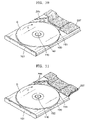
- FIG. 11 is a perspective view of an example of the dust adsorbing filter and the air guide shown in FIG. 10 .
- the dust adsorbing filter 297 and the air guide 295 may be disposed on a bottom surface of the tray 160 as well as the top surface of the tray 160 .
- the dust adsorbing filter 297 and the air guide 295 disposed on the bottom surface of the tray 160 adsorb dust contained in air flowing under the tray 160 .
- FIG. 12 is a perspective view of another example of the dust adsorbing filter and the air guide shown in FIG. 10 .
- a dust adsorbing filter 297 ′ and an air guide 295 ′ may be disposed on the upper case 170 . That is, the dust adsorbing filter 297 ′ is attached to a bottom surface of the upper case 170 , and the air guide 295 ′ protrudes from the bottom surface of the upper case 170 by a specified height toward the tray 160 .
- the air guide 295 ′ may be integrally formed with the upper case 170 when the upper case 170 is manufactured by pressing.
- the air guide 295 ′ may be made of a porous filtering material, such as sponge, and in this case, the air guide 295 ′ may be attached to the bottom surface of the upper case 170 using an adhesive.
- the optical disk drive comprising the dust removing apparatus according to the described embodiments of the present invention can minimize the amount of foreign substances, such as external dust, introduced into the disk drive, and collect and remove dust floating inside the disk drive, thereby preventing the performance of the optical pickup from decreasing.
Abstract
Description
Claims (23)
Priority Applications (2)
| Application Number | Priority Date | Filing Date | Title |
|---|---|---|---|
| US12/187,681 US7644418B2 (en) | 2004-04-14 | 2008-08-07 | Optical disk drive comprising dust removing apparatus |
| US12/591,452 US7836463B2 (en) | 2004-04-14 | 2009-11-19 | Optical disk drive comprising dust removing apparatus |
Applications Claiming Priority (2)
| Application Number | Priority Date | Filing Date | Title |
|---|---|---|---|
| KR10-2004-0025686A KR100539258B1 (en) | 2004-04-14 | 2004-04-14 | Optical disc drive having dust removing apparatus |
| KR2004-25686 | 2004-04-14 |
Related Child Applications (1)
| Application Number | Title | Priority Date | Filing Date |
|---|---|---|---|
| US12/187,681 Division US7644418B2 (en) | 2004-04-14 | 2008-08-07 | Optical disk drive comprising dust removing apparatus |
Publications (2)
| Publication Number | Publication Date |
|---|---|
| US20050235302A1 US20050235302A1 (en) | 2005-10-20 |
| US7441256B2 true US7441256B2 (en) | 2008-10-21 |
Family
ID=35097772
Family Applications (3)
| Application Number | Title | Priority Date | Filing Date |
|---|---|---|---|
| US10/983,725 Expired - Fee Related US7441256B2 (en) | 2004-04-14 | 2004-11-09 | Optical disk drive comprising dust removing apparatus |
| US12/187,681 Expired - Fee Related US7644418B2 (en) | 2004-04-14 | 2008-08-07 | Optical disk drive comprising dust removing apparatus |
| US12/591,452 Expired - Fee Related US7836463B2 (en) | 2004-04-14 | 2009-11-19 | Optical disk drive comprising dust removing apparatus |
Family Applications After (2)
| Application Number | Title | Priority Date | Filing Date |
|---|---|---|---|
| US12/187,681 Expired - Fee Related US7644418B2 (en) | 2004-04-14 | 2008-08-07 | Optical disk drive comprising dust removing apparatus |
| US12/591,452 Expired - Fee Related US7836463B2 (en) | 2004-04-14 | 2009-11-19 | Optical disk drive comprising dust removing apparatus |
Country Status (3)
| Country | Link |
|---|---|
| US (3) | US7441256B2 (en) |
| KR (1) | KR100539258B1 (en) |
| CN (1) | CN1684194B (en) |
Families Citing this family (5)
| Publication number | Priority date | Publication date | Assignee | Title |
|---|---|---|---|---|
| JP2005158101A (en) * | 2003-11-21 | 2005-06-16 | Hitachi Ltd | Disk array apparatus |
| US20080250394A1 (en) * | 2007-04-04 | 2008-10-09 | Microsoft Corporation | Synchronizing external documentation with code development |
| US20090055845A1 (en) * | 2007-08-23 | 2009-02-26 | Teruyuki Naka | Disc drive |
| KR101221810B1 (en) * | 2011-05-20 | 2013-01-14 | 도시바삼성스토리지테크놀러지코리아 주식회사 | Disk Drive and Method of selftest for fuction of optical pick-up unit |
| JP6293091B2 (en) * | 2015-05-21 | 2018-03-14 | 三菱電機株式会社 | Disk unit |
Citations (9)
| Publication number | Priority date | Publication date | Assignee | Title |
|---|---|---|---|---|
| JPH10162565A (en) | 1996-11-29 | 1998-06-19 | Nec Home Electron Ltd | Optical disk drive device |
| CN1203419A (en) | 1997-06-06 | 1998-12-30 | 索尼株式会社 | Disk device |
| JP2000011510A (en) | 1998-06-26 | 2000-01-14 | Nec Home Electron Ltd | Disk driving device |
| KR20020059532A (en) | 2001-01-08 | 2002-07-13 | 구자홍 | Door apparatus of disk drive |
| US6567361B1 (en) * | 1996-12-27 | 2003-05-20 | Sony Corporation | Disk tray formed with groove for preventing dust intrusion |
| JP2003157640A (en) | 2001-11-16 | 2003-05-30 | Sony Corp | Cartridge |
| KR20030063984A (en) | 2002-01-25 | 2003-07-31 | 엘지전자 주식회사 | Door tray for disk player |
| US6646974B2 (en) * | 2000-07-31 | 2003-11-11 | Sony Corporation | Disc support plate and disc recording and/or reproducing device |
| US20040004928A1 (en) | 2002-07-04 | 2004-01-08 | Samsung Electronics Co., Ltd., Suwon City, Korea | Disk drive for reducing noise |
Family Cites Families (3)
| Publication number | Priority date | Publication date | Assignee | Title |
|---|---|---|---|---|
| US5086422A (en) * | 1989-06-19 | 1992-02-04 | Ricoh Company, Ltd. | Optical disk apparatus |
| US5301178A (en) * | 1990-02-22 | 1994-04-05 | Olypus Optical Co., Ltd. | Drive unit for optical memory device with portion of drive means mounted outside a sealing means |
| JP2005243126A (en) * | 2004-02-25 | 2005-09-08 | Sony Corp | Disk driver |
-
2004
- 2004-04-14 KR KR10-2004-0025686A patent/KR100539258B1/en not_active IP Right Cessation
- 2004-11-09 US US10/983,725 patent/US7441256B2/en not_active Expired - Fee Related
-
2005
- 2005-04-06 CN CN2005100640615A patent/CN1684194B/en not_active Expired - Fee Related
-
2008
- 2008-08-07 US US12/187,681 patent/US7644418B2/en not_active Expired - Fee Related
-
2009
- 2009-11-19 US US12/591,452 patent/US7836463B2/en not_active Expired - Fee Related
Patent Citations (13)
| Publication number | Priority date | Publication date | Assignee | Title |
|---|---|---|---|---|
| JPH10162565A (en) | 1996-11-29 | 1998-06-19 | Nec Home Electron Ltd | Optical disk drive device |
| US6567361B1 (en) * | 1996-12-27 | 2003-05-20 | Sony Corporation | Disk tray formed with groove for preventing dust intrusion |
| US6246654B1 (en) * | 1997-06-06 | 2001-06-12 | Sony Corporation | Disk device |
| US6426932B2 (en) | 1997-06-06 | 2002-07-30 | Sony Corporation | Disk device |
| CN1203419A (en) | 1997-06-06 | 1998-12-30 | 索尼株式会社 | Disk device |
| US6650609B2 (en) * | 1997-06-06 | 2003-11-18 | Sony Corporation | Disk device |
| JP2000011510A (en) | 1998-06-26 | 2000-01-14 | Nec Home Electron Ltd | Disk driving device |
| US6646974B2 (en) * | 2000-07-31 | 2003-11-11 | Sony Corporation | Disc support plate and disc recording and/or reproducing device |
| KR20020059532A (en) | 2001-01-08 | 2002-07-13 | 구자홍 | Door apparatus of disk drive |
| JP2003157640A (en) | 2001-11-16 | 2003-05-30 | Sony Corp | Cartridge |
| KR20030063984A (en) | 2002-01-25 | 2003-07-31 | 엘지전자 주식회사 | Door tray for disk player |
| US20040004928A1 (en) | 2002-07-04 | 2004-01-08 | Samsung Electronics Co., Ltd., Suwon City, Korea | Disk drive for reducing noise |
| CN1467736A (en) | 2002-07-04 | 2004-01-14 | 三星电子株式会社 | Disk drive for reducing noise |
Non-Patent Citations (1)
| Title |
|---|
| First Office Action issued Sep. 21, 2007 in the corresponding Chinese Application No. 200510064061.5. |
Also Published As
| Publication number | Publication date |
|---|---|
| KR20050100459A (en) | 2005-10-19 |
| US7836463B2 (en) | 2010-11-16 |
| KR100539258B1 (en) | 2005-12-27 |
| US20090013338A1 (en) | 2009-01-08 |
| CN1684194A (en) | 2005-10-19 |
| US7644418B2 (en) | 2010-01-05 |
| US20050235302A1 (en) | 2005-10-20 |
| CN1684194B (en) | 2010-11-24 |
| US20100115539A1 (en) | 2010-05-06 |
Similar Documents
| Publication | Publication Date | Title |
|---|---|---|
| KR100557798B1 (en) | Disk device | |
| US7836463B2 (en) | Optical disk drive comprising dust removing apparatus | |
| CN1226741C (en) | Disc drive, rigid disc drive and casing for rigid disc drive | |
| KR101082809B1 (en) | Disc drive apparatus | |
| KR20100051932A (en) | Hard disk drive | |
| US7589932B2 (en) | Filtered air separator for disk drive | |
| US7307812B2 (en) | Filtering apparatus for disk drive | |
| KR20040007820A (en) | Filtering apparatus for hard disk drive | |
| CN1135548C (en) | Replay system for recording optic disc | |
| KR100788645B1 (en) | A disk cartridge | |
| US6954937B2 (en) | Disc guide device for disc player | |
| KR100442351B1 (en) | Disc cartridge in recorder for various type of disc | |
| KR100652430B1 (en) | Particlr extracting device of hard disk drive and hard disk drive having the same | |
| KR100588894B1 (en) | Apparatus for removing dust from an object lens of a pickup unit | |
| JPH0969282A (en) | Optical disc drive apparatus | |
| JP2013114722A (en) | Disk drive | |
| JP3096196B2 (en) | Optical disk drive | |
| JP4687261B2 (en) | Disk drive device and electronic device | |
| KR101008537B1 (en) | Main frame and optical disk drive with the same | |
| KR20080033449A (en) | Disk drive unit having an air flow guide element | |
| JP2007066432A (en) | Disk device | |
| KR20060024260A (en) | The disk tray | |
| JP2003228973A (en) | Optical disk device | |
| JPH11316966A (en) | Optical disk device | |
| JPH0515196U (en) | Dustproof device for optical disk player |
Legal Events
| Date | Code | Title | Description |
|---|---|---|---|
| AS | Assignment |
Owner name: SAMSUNG ELECTRONICS CO., LTD., KOREA, REPUBLIC OF Free format text: ASSIGNMENT OF ASSIGNORS INTEREST;ASSIGNORS:CHOI, MYUNG-RYUL;LEE, YOUNG-WON;LEE, JAE-SOO;REEL/FRAME:015971/0001 Effective date: 20041101 |
|
| STCF | Information on status: patent grant |
Free format text: PATENTED CASE |
|
| CC | Certificate of correction | ||
| FPAY | Fee payment |
Year of fee payment: 4 |
|
| FEPP | Fee payment procedure |
Free format text: PAYOR NUMBER ASSIGNED (ORIGINAL EVENT CODE: ASPN); ENTITY STATUS OF PATENT OWNER: LARGE ENTITY |
|
| FPAY | Fee payment |
Year of fee payment: 8 |
|
| FEPP | Fee payment procedure |
Free format text: MAINTENANCE FEE REMINDER MAILED (ORIGINAL EVENT CODE: REM.); ENTITY STATUS OF PATENT OWNER: LARGE ENTITY |
|
| LAPS | Lapse for failure to pay maintenance fees |
Free format text: PATENT EXPIRED FOR FAILURE TO PAY MAINTENANCE FEES (ORIGINAL EVENT CODE: EXP.); ENTITY STATUS OF PATENT OWNER: LARGE ENTITY |
|
| STCH | Information on status: patent discontinuation |
Free format text: PATENT EXPIRED DUE TO NONPAYMENT OF MAINTENANCE FEES UNDER 37 CFR 1.362 |
|
| FP | Lapsed due to failure to pay maintenance fee |
Effective date: 20201021 |
|
| AS | Assignment |
Owner name: TOSHIBA SAMSUNG STORAGE TECHNOLOGY KOREA CORPORATION, KOREA, REPUBLIC OF Free format text: ASSIGNMENT OF ASSIGNORS INTEREST;ASSIGNOR:SAMSUNG ELECTRONICS CO., LTD.;REEL/FRAME:060390/0021 Effective date: 20130201 |
|
| AS | Assignment |
Owner name: INTELLECTUAL DISCOVERY CO., LTD., KOREA, REPUBLIC OF Free format text: ASSIGNMENT OF ASSIGNORS INTEREST;ASSIGNOR:TOSHIBA SAMSUNG STORAGE TECHNOLOGY KOREA CORP.;REEL/FRAME:060390/0071 Effective date: 20200921 |
|
| AS | Assignment |
Owner name: TS-OPTICS CORPORATION, KOREA, REPUBLIC OF Free format text: ASSIGNMENT OF ASSIGNORS INTEREST;ASSIGNOR:INTELLECTUAL DISCOVERY CO., LTD.;REEL/FRAME:060390/0264 Effective date: 20220429 |