US7440152B2 - Holographic disk medium with servo marks - Google Patents
Holographic disk medium with servo marks Download PDFInfo
- Publication number
- US7440152B2 US7440152B2 US11/348,801 US34880106A US7440152B2 US 7440152 B2 US7440152 B2 US 7440152B2 US 34880106 A US34880106 A US 34880106A US 7440152 B2 US7440152 B2 US 7440152B2
- Authority
- US
- United States
- Prior art keywords
- servo
- disk medium
- reference beams
- holographic disk
- servo marks
- Prior art date
- Legal status (The legal status is an assumption and is not a legal conclusion. Google has not performed a legal analysis and makes no representation as to the accuracy of the status listed.)
- Expired - Fee Related, expires
Links
Images


Classifications
-
- G—PHYSICS
- G11—INFORMATION STORAGE
- G11B—INFORMATION STORAGE BASED ON RELATIVE MOVEMENT BETWEEN RECORD CARRIER AND TRANSDUCER
- G11B7/00—Recording or reproducing by optical means, e.g. recording using a thermal beam of optical radiation by modifying optical properties or the physical structure, reproducing using an optical beam at lower power by sensing optical properties; Record carriers therefor
- G11B7/004—Recording, reproducing or erasing methods; Read, write or erase circuits therefor
- G11B7/0065—Recording, reproducing or erasing by using optical interference patterns, e.g. holograms
-
- G—PHYSICS
- G11—INFORMATION STORAGE
- G11B—INFORMATION STORAGE BASED ON RELATIVE MOVEMENT BETWEEN RECORD CARRIER AND TRANSDUCER
- G11B7/00—Recording or reproducing by optical means, e.g. recording using a thermal beam of optical radiation by modifying optical properties or the physical structure, reproducing using an optical beam at lower power by sensing optical properties; Record carriers therefor
- G11B7/007—Arrangement of the information on the record carrier, e.g. form of tracks, actual track shape, e.g. wobbled, or cross-section, e.g. v-shaped; Sequential information structures, e.g. sectoring or header formats within a track
- G11B7/00772—Arrangement of the information on the record carrier, e.g. form of tracks, actual track shape, e.g. wobbled, or cross-section, e.g. v-shaped; Sequential information structures, e.g. sectoring or header formats within a track on record carriers storing information in the form of optical interference patterns, e.g. holograms
- G11B7/00781—Auxiliary information, e.g. index marks, address marks, pre-pits, gray codes
-
- G—PHYSICS
- G11—INFORMATION STORAGE
- G11B—INFORMATION STORAGE BASED ON RELATIVE MOVEMENT BETWEEN RECORD CARRIER AND TRANSDUCER
- G11B7/00—Recording or reproducing by optical means, e.g. recording using a thermal beam of optical radiation by modifying optical properties or the physical structure, reproducing using an optical beam at lower power by sensing optical properties; Record carriers therefor
- G11B7/08—Disposition or mounting of heads or light sources relatively to record carriers
- G11B7/083—Disposition or mounting of heads or light sources relatively to record carriers relative to record carriers storing information in the form of optical interference patterns, e.g. holograms
-
- G—PHYSICS
- G11—INFORMATION STORAGE
- G11B—INFORMATION STORAGE BASED ON RELATIVE MOVEMENT BETWEEN RECORD CARRIER AND TRANSDUCER
- G11B7/00—Recording or reproducing by optical means, e.g. recording using a thermal beam of optical radiation by modifying optical properties or the physical structure, reproducing using an optical beam at lower power by sensing optical properties; Record carriers therefor
- G11B7/08—Disposition or mounting of heads or light sources relatively to record carriers
- G11B7/09—Disposition or mounting of heads or light sources relatively to record carriers with provision for moving the light beam or focus plane for the purpose of maintaining alignment of the light beam relative to the record carrier during transducing operation, e.g. to compensate for surface irregularities of the latter or for track following
- G11B7/0938—Disposition or mounting of heads or light sources relatively to record carriers with provision for moving the light beam or focus plane for the purpose of maintaining alignment of the light beam relative to the record carrier during transducing operation, e.g. to compensate for surface irregularities of the latter or for track following servo format, e.g. guide tracks, pilot signals
-
- G—PHYSICS
- G11—INFORMATION STORAGE
- G11B—INFORMATION STORAGE BASED ON RELATIVE MOVEMENT BETWEEN RECORD CARRIER AND TRANSDUCER
- G11B7/00—Recording or reproducing by optical means, e.g. recording using a thermal beam of optical radiation by modifying optical properties or the physical structure, reproducing using an optical beam at lower power by sensing optical properties; Record carriers therefor
- G11B7/24—Record carriers characterised by shape, structure or physical properties, or by the selection of the material
- G11B7/2403—Layers; Shape, structure or physical properties thereof
- G11B7/24035—Recording layers
- G11B7/24044—Recording layers for storing optical interference patterns, e.g. holograms; for storing data in three dimensions [3D], e.g. volume storage
Definitions
- the present invention relates to a holographic disk medium with servo marks, and more specifically to a holographic disk medium having a common reflective layer for reflecting a servo beam and object and reference beams.
- Holographic storage systems are preferably equipped with a servo system to accurately control the position of the optical read/write system relative to a storage medium, e.g. a holographic optical disk.
- a servo system usually makes use of servo marks such as pits located on the storage medium.
- the holographic disk medium 1 includes a recording layer 2 , in which the holograms 6 are recorded, a mirror layer 3 for reflecting the servo beam 9 , a dichroic mirror layer 5 for reflecting the object and reference beams 8 , and two buffer layers 4 for separating the other layers 2 , 3 , 5 .
- Servo marks 7 are arranged in the mirror layer 3 .
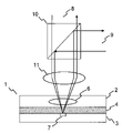
- the object and reference beams 8 and the servo beam 9 are combined by a beam splitter 10 and focused into the holographic disk medium 1 by a focusing lens 11 .
- a further prior art concept which is disclosed in EP 1471507, uses the same layer for reflecting the servo beam and the object and reference beams. In this way the dichroic layer is no more required, which makes the manufacturing of the holographic disk medium significantly easier. According to this solution the beams are laterally separated. A narrow track/groove or narrow pits are used for the generation of focus and track information. A wide mirror or land area between the tracks/grooves or pits is provided as a mirror located in the Fourier plane of the object and reference beams.
- a recording structure on a holographic disk medium in accordance with this solution is depicted in FIG. 2 .
- a band 13 with servo marks 7 is arranged between each band 12 of holograms 6 .
- the holograms do not overlap with the servo marks. No radial/lateral shift multiplexing is applied. Depending on the size of the holograms 6 , i.e. the Fourier image, large beam separations are required. This leads to large aberrations of the servo beam, in particular in case of objective lenses with high numerical aperture (NA). In addition, only tangential shift multiplexing can be used.
- a hologram recording medium has a hologram layer and a servo layer.
- the tracks in the servo layer are located at least partly below the holograms.
- the track width in the servo layer is either much larger or much smaller than the diameter of the object and reference beams.
- this object is achieved by a holographic disk medium with a recording layer for recording holograms and a reflective layer for reflecting a servo beam and object and reference beams, wherein servo marks are located in the reflective layer at least partly below the holograms, and wherein the servo marks are designed such that their influence on the object and reference beams is minimized.
- the special arrangement and design of the servo marks has the advantage that it is not necessary to laterally separate the servo beam and the object and reference beams. This allows to use an identical light path for the servo beam and the object and reference beams (readout and recording beams), which simplifies the alignment of the laser beams.
- a further advantage is that besides tangential shift multiplexing also lateral/radial shift multiplexing can be realized.
- a holographic disk medium is easy to manufacture.
- the required optical quality of the mirror layer for the object and reference beams is easy to control and can be manufactured by moulding of substrates from a dedicated stamper.
- neither a dichroic reflective layer nor an additional buffer layer with high flatness, small roughness, low thickness variation etc. is required.
- the reflective layer is the same for the servo beam and the object and reference beams and can be very similar to the reflective layer of a DVD-ROM.
- the servo beam has a first wavelength and the object and reference beams have a second wavelength, the servo marks having an effective depth of half the wavelength of the object and reference beams.
- Effective depth means that the actual depth is an odd integer multiple of half the wavelength of the object and reference beams.
- the phase of the light reflected by a servo mark and the light reflected by the area around the servo mark add up coherently and the servo marks have no influence. Due to the wavelength difference, the effective depth of the servo marks will be different from half the wavelength of the servo beam. Therefore, the servo marks lead to a modulation of the reflected servo beam, which can be used for generating a servo signal.
- the object and reference beams have a first direction of polarization and the servo beam has a second direction of polarization, the servo marks having a width and a depth adapted to minimize their influence on the object and reference beams.
- the interaction of small servo marks with a polarized light beam depends strongly on the direction of polarization.
- By varying the width of a servo marks for a given depth of the servo marks it is possible to minimize their influence on the object and reference beams having the first direction of polarization. At the same the influence on the perpendicular direction of polarization, and hence on the servo beam, can be maximized.
- the holograms are aligned along a track. This simplifies the readout and/or recording operation.
- the holograms are arranged overlappingly by tangential and/or lateral/radial shift multiplexing. In this way higher storage densities are achieved.
- the recording material of the recording layer does not change the optical properties of the object and reference beams. This applies especially to the direction of polarization of the beams, in order to keep the influence of the servo marks on these beams minimized.
- FIG. 1 depicts a holographic storage system according to a first prior art concept
- FIG. 2 schematically shows a recording structure on a holographic disk medium according to a second prior art concept
- FIG. 3 depicts a holographic storage system using a holographic disk medium according to the invention.
- FIG. 4 schematically shows a recording structure on a holographic disk medium according to the invention.
- FIG. 3 depicts a holographic storage system using a holographic disk medium 1 according to the invention.
- the servo marks 7 (pits or groove) are integrated into the mirror layer 3 and lie directly below the hologram 6 separated by an optional buffer layer 4 .
- a buffer layer 4 has the advantage that the holographic material of the recording layer 2 is not recorded in the focus of the focusing lens 11 , where the intensity is high and a saturation could occur. However, it is likewise possible to omit the buffer layer 4 .
- the object and reference beams 8 and the servo beam 9 use a similar optical path through the objective lens 11 .
- the servo beam 9 is separated from the object and reference beams 8 by a dichroic beam splitter 10 .
- the servo marks 7 degrade the holographic write and read process.
- the shape and in particular the depth of the servo marks 7 is chosen in such a way that the servo mark is essentially ‘invisible’ to the signal and reference beams 8 . This can be achieved by using different wavelengths for the servo beam 9 and the object and reference beams 8 .
- the servo marks 7 are designed in such a way that they have an effective depth of half the wavelength of the object and reference beams 8 .
- the phase of the light reflected by a servo mark 7 and the light reflected by the area around the servo mark 7 add up coherently, and, therefore the servo marks 7 are invisible. Due to the wavelength difference, the effective depth of the servo marks 7 will be different from half the wavelength of the servo beam 9 . Therefore, the servo marks 7 lead to a modulation of the reflected servo beam 9 and can be used for generating a servo signal.
- the servo beam 9 and the object and reference beams 8 have different directions of polarization.
- the interaction of small servo marks 7 e.g. DVD ROM pits, with a polarized light beam depends strongly on the direction of polarization.
- By varying the width of a servo marks 7 for a given depth of the servo marks 7 it is possible to minimize their influence on the object and reference beams 8 having a first direction of polarization, whereas the influence for the perpendicular direction of polarization is maximized.
- the dichroic beam splitter 10 is replaced by a polarizing beam splitter 10 .
- the servo marks 7 are located in a well-defined area below the holograms 6 . Therefore, distortion caused by the structure of the servo marks 7 during readout of a hologram 6 is systematical and limited to certain Fourier components of the stored information. Though only a small degradation of the readout performance is to be expected, the knowledge of the well-known and systematical distortion caused by the servo marks 7 can be used to correct the readout path and, consequently, to improve the readout performance. Dedicated pre- and/or post-processing strategies can be applied to compensate for the systematic distortion, e.g. an amplification of the attenuated Fourier components.
- FIG. 4 schematically shows a recording structure on a holographic disk medium 1 according to the invention.
- the holograms 6 are aligned along a track 12 and may overlap.
- There is a single track 13 i.e. a row with servo marks 7 , for each row 12 of overlapping holograms 6 .
- the servo marks 7 are placed directly into the reflective layer 3 of the holographic disk medium 1 . This makes the reflective layer 3 of the holographic disk medium 1 quite similar to e.g. a DVD ROM disk, if a red laser (650 nm) is used for the servo beam 9 .
- the servo marks 7 are used for generating the servo signals, i.e. focusing and tracking error signals, and to obtain address information.
- longitudinal and radial/lateral shift multiplexing is realized.
Landscapes
- Optical Recording Or Reproduction (AREA)
- Optical Head (AREA)
- Holo Graphy (AREA)
- Optical Record Carriers And Manufacture Thereof (AREA)
Abstract
Description
Claims (11)
Applications Claiming Priority (2)
| Application Number | Priority Date | Filing Date | Title |
|---|---|---|---|
| EP05101030.4 | 2005-02-11 | ||
| EP05101030A EP1691355A1 (en) | 2005-02-11 | 2005-02-11 | Holographic disk medium with servo marks |
Publications (2)
| Publication Number | Publication Date |
|---|---|
| US20060181999A1 US20060181999A1 (en) | 2006-08-17 |
| US7440152B2 true US7440152B2 (en) | 2008-10-21 |
Family
ID=34938717
Family Applications (1)
| Application Number | Title | Priority Date | Filing Date |
|---|---|---|---|
| US11/348,801 Expired - Fee Related US7440152B2 (en) | 2005-02-11 | 2006-02-07 | Holographic disk medium with servo marks |
Country Status (7)
| Country | Link |
|---|---|
| US (1) | US7440152B2 (en) |
| EP (1) | EP1691355A1 (en) |
| JP (1) | JP4506679B2 (en) |
| KR (1) | KR101234207B1 (en) |
| CN (1) | CN1819038B (en) |
| MY (1) | MY139678A (en) |
| TW (1) | TWI395216B (en) |
Families Citing this family (9)
| Publication number | Priority date | Publication date | Assignee | Title |
|---|---|---|---|---|
| HU0700131D0 (en) * | 2007-02-06 | 2007-05-02 | Bayer Innovation Gmbh | Method of reading a fourier a hologram recorder on a holographic storage medium and a holographic storage system |
| TWI405203B (en) * | 2007-04-13 | 2013-08-11 | Ibm | Dual-path optical recording media and an apparatus for accessing thereof, and method for managing service transactions using the apparatus |
| US8180950B2 (en) * | 2007-06-15 | 2012-05-15 | International Business Machines Corporation | Apparatus and method to manage information using an optical and holographic data storage medium |
| US8274874B2 (en) | 2008-02-04 | 2012-09-25 | International Business Machines Corporation | Apparatus, system, and method for locating and fast-searching units of digital information in volume, optical-storage disks |
| US7986602B2 (en) | 2008-02-12 | 2011-07-26 | International Business Machines Corporation | Apparatus and method to set a rotation rate for an optical and holographic data storage medium |
| US7995444B2 (en) * | 2008-02-12 | 2011-08-09 | International Business Machines Corporation | Apparatus and method to store and retrieve information using an optical holographic data storage medium |
| JP5621227B2 (en) * | 2009-08-26 | 2014-11-12 | ソニー株式会社 | Optical information apparatus and optical pickup |
| WO2011064838A1 (en) * | 2009-11-24 | 2011-06-03 | 株式会社 東芝 | Information storage device |
| CN107767887A (en) * | 2017-12-06 | 2018-03-06 | 苏州盤谷信息光学有限公司 | A kind of holographic memory device based on dichroic reflective layer |
Citations (5)
| Publication number | Priority date | Publication date | Assignee | Title |
|---|---|---|---|---|
| US20040001400A1 (en) | 1999-07-29 | 2004-01-01 | Siros Technologies, Inc., A California Corporation | Optical data storage system with focus and tracking error correction |
| US6721076B2 (en) * | 2001-08-03 | 2004-04-13 | Inphase Technologies, Inc. | System and method for reflective holographic storage with associated multiplexing techniques |
| EP1471507A2 (en) | 2003-04-23 | 2004-10-27 | TDK Corporation | A method for recording and reproducing holographic data and an apparatus therefor |
| US20050002311A1 (en) | 2003-05-09 | 2005-01-06 | Katsutaro Ichihara | Hologram recording medium and method of hologram recording and reproduction |
| US20060109774A1 (en) * | 2003-02-06 | 2006-05-25 | Optware Corporation | Optical information recording medium |
Family Cites Families (9)
| Publication number | Priority date | Publication date | Assignee | Title |
|---|---|---|---|---|
| JP3393064B2 (en) * | 1998-02-27 | 2003-04-07 | 株式会社オプトウエア | Optical information recording medium |
| JP2003085768A (en) * | 2001-09-13 | 2003-03-20 | Optware:Kk | Optical information recording apparatus and method |
| JP4548762B2 (en) * | 2001-09-13 | 2010-09-22 | 新オプトウエア株式会社 | Optical information recording medium |
| US6931650B2 (en) * | 2001-12-27 | 2005-08-16 | Matsushita Electric Industrial Co., Ltd. | Pickup device and disk drive |
| JP2004033510A (en) * | 2002-07-04 | 2004-02-05 | Hitachi Hometec Ltd | Leg bath |
| JPWO2004021339A1 (en) * | 2002-08-01 | 2005-12-22 | パイオニア株式会社 | Hologram recording / reproducing apparatus and method, and hologram recording medium |
| JP2004158113A (en) * | 2002-11-06 | 2004-06-03 | Memory Tec Kk | Optical information recording medium |
| JP4156911B2 (en) * | 2002-12-02 | 2008-09-24 | 新オプトウエア株式会社 | Optical information recording medium, optical information recording apparatus, and optical information reproducing apparatus |
| JP4162511B2 (en) * | 2003-03-03 | 2008-10-08 | Tdk株式会社 | Hologram recording / reproducing method and hologram recording medium |
-
2005
- 2005-02-11 EP EP05101030A patent/EP1691355A1/en not_active Withdrawn
-
2006
- 2006-01-27 CN CN2006100045332A patent/CN1819038B/en not_active Expired - Fee Related
- 2006-02-06 KR KR1020060011037A patent/KR101234207B1/en not_active Expired - Fee Related
- 2006-02-07 US US11/348,801 patent/US7440152B2/en not_active Expired - Fee Related
- 2006-02-08 MY MYPI20060526A patent/MY139678A/en unknown
- 2006-02-09 JP JP2006032457A patent/JP4506679B2/en not_active Expired - Fee Related
- 2006-02-10 TW TW095104472A patent/TWI395216B/en not_active IP Right Cessation
Patent Citations (5)
| Publication number | Priority date | Publication date | Assignee | Title |
|---|---|---|---|---|
| US20040001400A1 (en) | 1999-07-29 | 2004-01-01 | Siros Technologies, Inc., A California Corporation | Optical data storage system with focus and tracking error correction |
| US6721076B2 (en) * | 2001-08-03 | 2004-04-13 | Inphase Technologies, Inc. | System and method for reflective holographic storage with associated multiplexing techniques |
| US20060109774A1 (en) * | 2003-02-06 | 2006-05-25 | Optware Corporation | Optical information recording medium |
| EP1471507A2 (en) | 2003-04-23 | 2004-10-27 | TDK Corporation | A method for recording and reproducing holographic data and an apparatus therefor |
| US20050002311A1 (en) | 2003-05-09 | 2005-01-06 | Katsutaro Ichihara | Hologram recording medium and method of hologram recording and reproduction |
Non-Patent Citations (1)
| Title |
|---|
| Search Report, Aug. 4, 2005. |
Also Published As
| Publication number | Publication date |
|---|---|
| CN1819038A (en) | 2006-08-16 |
| CN1819038B (en) | 2010-12-08 |
| TW200632902A (en) | 2006-09-16 |
| JP4506679B2 (en) | 2010-07-21 |
| US20060181999A1 (en) | 2006-08-17 |
| MY139678A (en) | 2009-10-30 |
| EP1691355A1 (en) | 2006-08-16 |
| JP2006221789A (en) | 2006-08-24 |
| KR20060090926A (en) | 2006-08-17 |
| KR101234207B1 (en) | 2013-02-19 |
| TWI395216B (en) | 2013-05-01 |
Similar Documents
| Publication | Publication Date | Title |
|---|---|---|
| KR100965884B1 (en) | Optical pickup | |
| KR100465264B1 (en) | Optical detector, optical pickup and optical information reproducing apparatus using optical pickup | |
| US20050141391A1 (en) | Optical pickup | |
| JP4538759B2 (en) | Information recording apparatus, information reproducing apparatus, and optical pickup | |
| US7440152B2 (en) | Holographic disk medium with servo marks | |
| JP4037034B2 (en) | Information recording / reproducing device | |
| JP4964306B2 (en) | Optical head device | |
| US20080049581A1 (en) | Optical pick-up | |
| US20050036432A1 (en) | Optical pickup capable of reducing focus offset and optical recording and/or reproducing apparatus employing the same | |
| EP1691356A2 (en) | Holographic disk medium with servo marks | |
| KR20090033080A (en) | Optical pickup device, optical recording medium drive device and signal recording / reproducing method | |
| WO2007113983A1 (en) | Optical pickup device | |
| JP4781601B2 (en) | Optical pickup device and manufacturing method thereof | |
| JPH1027373A (en) | Optical head and optical disk device | |
| KR101046680B1 (en) | Optical pickup and optical device | |
| JP2005203041A (en) | Optical integrated unit and optical pickup device | |
| JP2006338782A (en) | Optical pickup device and information recording / reproducing device | |
| CN102270470B (en) | Optical pickup device and optical disc apparatus | |
| US20060221785A1 (en) | Optical disk apparatus and an optical disk playback method | |
| KR20070044275A (en) | Optical pickup | |
| US20070297313A1 (en) | Optical pickup | |
| KR100600587B1 (en) | Optical pickup | |
| JPH10255317A (en) | Optical disk drive | |
| JP2004259413A (en) | Optical pickup device and objective lens therefor | |
| KR20080061751A (en) | Optical pickup |
Legal Events
| Date | Code | Title | Description |
|---|---|---|---|
| AS | Assignment |
Owner name: THOMSON LICENSING, FRANCE Free format text: ASSIGNMENT OF ASSIGNORS INTEREST;ASSIGNORS:KNITTEL, JOACHIM;RICHTER, HARTMUT;KNAPPMANN, STEPHAN;REEL/FRAME:017563/0104 Effective date: 20051102 |
|
| STCF | Information on status: patent grant |
Free format text: PATENTED CASE |
|
| FPAY | Fee payment |
Year of fee payment: 4 |
|
| FPAY | Fee payment |
Year of fee payment: 8 |
|
| FEPP | Fee payment procedure |
Free format text: MAINTENANCE FEE REMINDER MAILED (ORIGINAL EVENT CODE: REM.); ENTITY STATUS OF PATENT OWNER: LARGE ENTITY |
|
| LAPS | Lapse for failure to pay maintenance fees |
Free format text: PATENT EXPIRED FOR FAILURE TO PAY MAINTENANCE FEES (ORIGINAL EVENT CODE: EXP.); ENTITY STATUS OF PATENT OWNER: LARGE ENTITY |
|
| STCH | Information on status: patent discontinuation |
Free format text: PATENT EXPIRED DUE TO NONPAYMENT OF MAINTENANCE FEES UNDER 37 CFR 1.362 |
|
| FP | Lapsed due to failure to pay maintenance fee |
Effective date: 20201021 |