US7439807B2 - Method and system for generating a temperature-compensated control signal - Google Patents
Method and system for generating a temperature-compensated control signal Download PDFInfo
- Publication number
- US7439807B2 US7439807B2 US11/471,408 US47140806A US7439807B2 US 7439807 B2 US7439807 B2 US 7439807B2 US 47140806 A US47140806 A US 47140806A US 7439807 B2 US7439807 B2 US 7439807B2
- Authority
- US
- United States
- Prior art keywords
- transistor
- control signal
- current
- temperature
- coupled
- Prior art date
- Legal status (The legal status is an assumption and is not a legal conclusion. Google has not performed a legal analysis and makes no representation as to the accuracy of the status listed.)
- Expired - Fee Related, expires
Links
Images


Classifications
-
- H—ELECTRICITY
- H03—ELECTRONIC CIRCUITRY
- H03G—CONTROL OF AMPLIFICATION
- H03G3/00—Gain control in amplifiers or frequency changers
- H03G3/20—Automatic control
- H03G3/30—Automatic control in amplifiers having semiconductor devices
- H03G3/3036—Automatic control in amplifiers having semiconductor devices in high-frequency amplifiers or in frequency-changers
-
- H—ELECTRICITY
- H03—ELECTRONIC CIRCUITRY
- H03G—CONTROL OF AMPLIFICATION
- H03G2201/00—Indexing scheme relating to subclass H03G
- H03G2201/70—Gain control characterized by the gain control parameter
- H03G2201/708—Gain control characterized by the gain control parameter being temperature
Definitions
- This disclosure is generally directed to variable gain amplifiers and, more specifically, to a method and system for generating a temperature-compensated control signal.
- the transmit path generally includes multiple variable gain amplifiers (VGAs).
- VGAs variable gain amplifiers
- the gain control equation for each of the VGAs includes the absolute temperature, T. Therefore, the gain performance of conventional a VGA is a function of temperature. Because of this, VGA performance may be unreliable in changing environments. Problems with this include an increased need for RF calibration in order to keep the VGAs functioning properly.
- This disclosure provides a method and system for generating a temperature-compensated control signal.
- a method in one aspect, includes receiving a constant control signal.
- a temperature-compensated control signal is generated based on the constant control signal.
- the temperature-compensated control signal is provided to a variable gain amplifier.
- the temperature-compensated control signal is operable to cause the variable gain amplifier to function independently of temperature.
- a temperature compensation control circuit in another aspect, includes a thermal voltage generator, a voltage-to-current converter, and a current multiplier.
- the thermal voltage generator is operable to generate a thermal voltage.
- the voltage-to-current converter is coupled to the thermal voltage generator and is operable to convert the thermal voltage into a thermal current.
- the current multiplier is coupled to the voltage-to-current converter and is operable to multiply the thermal current by an input current to generate an output current.
- an automatic gain control system in yet another aspect, includes a variable gain amplifier and a temperature compensation control circuit.
- the variable gain amplifier is operable to receive a variable gain amplifier (VGA) input signal and to generate a VGA output signal based on the VGA input signal.
- the temperature compensation control circuit is coupled to the variable gain amplifier.
- the temperature compensation control circuit is operable to generate a temperature-compensated control signal based on a constant control signal and to provide the temperature-compensated control signal to the variable gain amplifier.
- the variable gain amplifier is further operable to generate the VGA output signal based on the temperature-compensated control signal.
- FIG. 1 illustrates an automatic gain control system that is capable of varying gain exponentially with respect to a control signal according to one embodiment of this disclosure
- FIG. 2 illustrates a simplified circuit design of the gain control circuit of FIG. 1 according to one embodiment of this disclosure
- FIG. 3 illustrates a circuit diagram of the gain control circuit of FIG. 1 or 2 and the variable gain amplifier of FIG. 1 according to one embodiment of this disclosure
- FIG. 4 illustrates a method for varying gain exponentially with respect to a control signal using the gain control circuit of FIGS. 1 , 2 or 3 according to one embodiment of this disclosure
- FIG. 5 illustrates an automatic gain control system that is capable of generating a temperature-compensated control signal according to one embodiment of this disclosure
- FIG. 6 illustrates a block diagram of the temperature compensation control circuit of FIG. 5 according to one embodiment of this disclosure
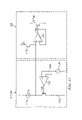
- FIG. 7A illustrates a circuit diagram of the thermal voltage generator of FIG. 6 according to one embodiment of this disclosure
- FIG. 7B illustrates a circuit diagram of the thermal voltage generator of FIG. 6 according to another embodiment of this disclosure.
- FIG. 8A illustrates a circuit diagram of the current multiplier of FIG. 6 according to one embodiment of this disclosure
- FIG. 8B illustrates a circuit diagram of the current multiplier of FIG. 6 according to another embodiment of this disclosure.
- FIG. 9 illustrates a circuit diagram of the voltage-to-current converter of FIG. 6 according to one embodiment of this disclosure.
- FIG. 10 illustrates a circuit diagram of the current-to-voltage converter of FIG. 6 according to one embodiment of this disclosure
- FIG. 11 illustrates a circuit diagram of the input circuit, the voltage-to-current converter and the current multiplier of FIG. 6 according to one embodiment of this disclosure
- FIG. 12 illustrates a method for generating a temperature-compensated control signal using the temperature compensation control circuit of FIG. 5 or 6 according to one embodiment of this disclosure.
- FIG. 13 illustrates an automatic gain control system that is capable of varying gain exponentially with respect to a temperature-compensated control signal according to one embodiment of this disclosure.
- FIGS. 1 through 13 discussed below, and the various embodiments used to describe the principles of the present invention in this patent document are by way of illustration only and should not be construed in any way to limit the scope of the invention. Those skilled in the art will understand that the principles of the present invention may be implemented in any suitably arranged variable gain circuit.
- FIG. 1 illustrates an automatic gain control system 100 that is capable of varying the gain of a variable gain amplifier 105 exponentially with respect to a control signal based on a modified version of that control signal received from a gain control circuit 110 according to one particular embodiment of this disclosure.
- the automatic gain control system 100 may be implemented in a transmit path of a communication system.
- the automatic gain control system 100 may be implemented in any other suitable system without departing from the scope of the present disclosure.
- the gain control circuit 110 is operable to receive a primary control signal 135 and to generate a secondary control signal 130 based on the primary control signal 135 in order to exponentially vary the gain of the variable gain amplifier 105 .
- the variable gain amplifier 105 which is coupled to the gain control circuit 110 , is operable to receive a variable gain amplifier (VGA) input signal 120 and to generate a VGA output signal 125 by amplifying the VGA input signal 120 based on the secondary control signal 130 .
- VGA variable gain amplifier
- the gain of the variable gain amplifier 105 varies exponentially with respect to the primary control signal 135 instead of with respect to the secondary control signal 130 .
- variable gain amplifier 105 and the gain control circuit 110 are part of an automatic gain control system 100 that also comprises an amplifier 150 , a detector 155 , a filter 160 , and a differential amplifier 165 .
- variable gain amplifier 105 and the gain control circuit 110 may be implemented in a differently arranged automatic gain control system or in any other suitable system without departing from the scope of the present disclosure.
- the amplifier 150 is coupled to the variable gain amplifier 105 and is operable to further amplify the VGA output signal 125 in order to generate a system output signal 175 that is at a higher level than the VGA output signal 125 for use in an application in which the automatic gain control system 100 is implemented.
- the detector 155 which is coupled to the amplifier 150 , is operable to detect one or more parameters associated with the system output signal 175 , such as amplitude, carrier frequency, modulation index or the like, and to generate a detected parameter signal 180 based on the detection.
- the filter 160 which may comprise a low-pass or other suitable filter, is coupled to the detector 155 and is operable to filter out any undesired components to generate a filtered signal 185 .
- the differential amplifier 165 is coupled to the filter 160 and is operable to compare the filtered signal 185 to a reference signal 190 in order to generate the primary control signal 135 .
- the gain control circuit 110 which is coupled to the differential amplifier 165 , may then generate the secondary control signal 130 based on the primary control signal 135 and exponentially vary the gain of the variable gain amplifier 105 with respect to the primary control signal 135 using the secondary control signal 130 .
- the gain control circuit 110 is operable to generate the secondary control signal 130 in such a manner as to maximize the ability of the variable gain amplifier 105 to vary its gain exponentially (i.e., in a linear-in-dB fashion) with respect to the primary control signal 135 .
- FIG. 2 illustrates a simplified circuit design of the gain control circuit 110 according to one embodiment of this disclosure.
- This embodiment of the gain control circuit 110 comprises a plurality of transistors 205 , 210 and 215 , a current mirror 220 , a current-controlled voltage source (CCVS) 225 , and a current source 230 .
- CCVS current-controlled voltage source
- the primary control signal 135 is applied across one of the transistors (transistor 205 ) in a differential pair (transistors 205 and 210 ).
- transistor 215 is matched to transistor 210 and is biased in the same direction as transistor 210 in order to cancel the voltage drop across transistor 210 .
- the output current, identified as I c1 is normalized to the current source 230 , which provides the input current identified as I 0 .
- ⁇ V be2 is added to the differential pair 205 and 210 (as part of the CCVS 225 ).
- ⁇ V c is added to the circuit (also as part of the CCVS 225 ).
- V in ⁇ V be1 +V c .
- the secondary control signal 130 is generated at the bases of transistors 205 and 210 , as indicated by the two nodes 130 a and 130 b.
- FIG. 3 illustrates a circuit diagram of the variable gain amplifier 105 and the gain control circuit 110 according to one embodiment of this disclosure.
- the gain control circuit 110 comprises a plurality of transistors, an operational amplifier and a current source.
- the transistors Q 1 a and Q 1 b form a first current mirror
- Q 2 a and Q 2 b form a second current mirror
- Q 3 a , Q 3 b and Q 3 c form a third current mirror.
- the transistors Q 4 and Q 7 are matched.
- V be is the same
- V be is the same.
- the primary control signal 135 is applied across transistors Q 4 and Q 7 , and the secondary control signal 130 is generated from transistors Q 6 and Q 7 , as indicated at nodes 130 a and 130 b , respectively.
- the secondary control signal 130 is applied to the variable gain amplifier 105 at transistors Q 8 and Q 9 .
- FIG. 4 illustrates a method for exponentially varying gain in the variable gain amplifier 105 with respect to a primary control signal 135 using the gain control circuit 110 according to one embodiment of this disclosure.
- This embodiment corresponds to the automatic gain control system 100 illustrated in FIG. 1 .
- portions of this embodiment may be implemented in any other suitable system without departing from the scope of the present disclosure.
- the embodiment of FIG. 4 illustrates a method for exponentially varying gain in the variable gain amplifier 105 with respect to a primary control signal 135 using the gain control circuit 110 according to one embodiment of this disclosure.
- This embodiment corresponds to the automatic gain control system 100 illustrated in FIG. 1 .
- portions of this embodiment may be implemented in any other suitable system without departing from the scope of the present disclosure.
- the method begins at step 405 where the gain control circuit 110 receives a primary control signal 135 from the differential amplifier 165 .
- the gain control circuit 110 generates a secondary control signal 130 based on the primary control signal 135 .
- the gain control circuit 110 generates the secondary control signal 130 by applying the primary control signal 135 directly across one transistor (such as transistor 205 or Q 6 ) in a differential pair of transistors (such as transistors 205 and 210 or Q 6 and Q 7 ).
- the gain control circuit 110 provides the secondary control signal 130 to the variable gain amplifier (VGA) 105 in order to exponentially vary the gain of the variable gain amplifier 105 with respect to the primary control signal 135 .
- VGA variable gain amplifier
- the variable gain amplifier 105 receives the secondary control signal 130 from the gain control circuit 110 and receives a VGA input signal 120 from any suitable component coupled to the automatic gain control system 100 .
- the variable gain amplifier 105 generates a VGA output signal 125 based on both the VGA input signal 120 and the secondary control signal 130 by amplifying the VGA input signal 120 with a gain that is controlled by the secondary control signal 130 .
- the amplifier 150 amplifies the VGA output signal 125 to generate a system output signal 175 for the automatic gain control system 100 .
- the detector 155 detects one or more parameters of the system output signal 175 to generate a detected parameter signal 180 .
- the filter 160 filters the detected parameter signal 180 to generate a filtered signal 185 .
- the differential amplifier 165 compares the filtered signal 185 to a reference signal 190 .
- the differential amplifier 165 generates the primary control signal 135 based on the comparison of the filtered signal 185 to the reference signal 190 .
- the differential amplifier 165 provides the primary control signal 135 to the gain control circuit 110 , and the method returns to step 405 where the gain control circuit 110 continues to receive the primary control signal 135 .
- the gain (in dB) of at least one variable gain amplifier 105 in a transmit path of a communication system may be linearly adjusted, making compliance with power adjustment specifications and other system considerations easier.
- the transfer function is linear-in-dB even at relatively large control voltages. This results in the variable gain amplifier 105 having an improved performance as compared to a variable gain amplifier with a gain that is adjusted only by a primary control signal from a differential amplifier.
- the variable gain amplifier 105 has a reduced requirement for RF calibration.
- FIG. 5 illustrates an automatic gain control system 500 that is capable of generating a temperature-compensated control signal for varying the gain of a variable gain amplifier 505 according to one embodiment of this disclosure.
- the automatic gain control system 500 may be implemented in a transmit path of a communication system.
- the automatic gain control system 500 may be implemented in any other suitable system without departing from the scope of the present disclosure.
- the automatic gain control system 500 comprises a temperature compensation control circuit 510 that is coupled to the variable gain amplifier 505 .
- the temperature compensation control circuit 510 is operable to receive a constant control signal 515 and to generate a temperature-compensated control signal 520 based on the constant control signal 515 in order to cause the variable gain amplifier 505 to function independently of temperature.
- a “constant control signal” means a control signal that is not temperature-compensated.
- the constant control signal 515 may be altered in order to adjust the gain of the variable gain amplifier 505 .
- the constant control signal 515 is not altered to compensate for temperature differences that may affect the performance of the variable gain amplifier 505 .
- the variable gain amplifier 505 which is coupled to the temperature compensation control circuit 510 , is operable to receive a variable gain amplifier (VGA) input signal 530 and to generate a VGA output signal 535 by amplifying the VGA input signal 530 based on the temperature-compensated control signal 520 .
- VGA variable gain amplifier
- variable gain amplifier 505 and the temperature compensation control circuit 510 are part of an automatic gain control system 500 that also comprises an amplifier 550 , a detector 555 , a filter 560 , and a differential amplifier 565 .
- variable gain amplifier 505 and the temperature compensation control circuit 510 may be implemented in a differently arranged automatic gain control system or in any other suitable system without departing from the scope of the present disclosure.
- the amplifier 550 is coupled to the variable gain amplifier 505 and is operable to further amplify the VGA output signal 535 in order to generate a system output signal 575 that is at a higher level than the VGA output signal 535 for use in an application in which the automatic gain control system 500 is implemented.
- the detector 555 which is coupled to the amplifier 550 , is operable to detect one or more parameters associated with the system output signal 575 , such as amplitude, carrier frequency, modulation index or the like, and to generate a detected parameter signal 580 based on the detection.
- the filter 560 which may comprise a low-pass or other suitable filter, is coupled to the detector 555 and is operable to filter out any undesired components to generate a filtered signal 585 .
- the differential amplifier 565 is coupled to the filter 560 and is operable to compare the filtered signal 585 to a reference signal 590 in order to generate the constant control signal 515 .
- the temperature compensation control circuit 510 which is coupled to the differential amplifier 565 , may then generate the temperature-compensated control signal 520 based on the constant control signal 515 . As described in more detail below in connection with FIGS. 6-12 , the temperature compensation control circuit 510 is operable to generate the temperature-compensated control signal 520 such that the variable gain amplifier 505 may function independently of temperature.
- FIG. 6 illustrates a block diagram of the temperature compensation control circuit 510 according to one embodiment of this disclosure.
- the temperature compensation control circuit 510 comprises a thermal voltage generator 605 , an input circuit 615 , two voltage-to-current (V-I) converters 610 and 620 , a current multiplier 625 , and a current-to-voltage (I-V) converter 630 .
- V-I voltage-to-current
- I-V current-to-voltage
- the thermal voltage generator 605 is operable to generate a thermal voltage 640 .
- the first V-I converter 610 which is coupled to the thermal voltage generator 605 , is operable to convert the thermal voltage 640 into a thermal current 645 .
- the input circuit 615 is operable to receive the constant control signal 515 and to generate an adjusted constant control signal 650 based on the constant control signal 515 by applying an offset, if desired. In generating the adjusted constant control signal 650 , the input circuit 615 is operable to define a starting point for gain control.
- the second V-I converter 620 which is coupled to the input circuit 615 , is operable to convert the adjusted constant control signal 650 into an input current 655 .
- the current multiplier 625 which is coupled to the V-I converters 610 and 620 , is operable to multiply the thermal current 645 and the input current 655 to generate an output current 660 .
- the I-V converter 630 which is coupled to the current multiplier 625 , is operable to convert the output current 660 into the temperature-compensated control signal 520 .
- FIG. 7A illustrates a circuit diagram of the thermal voltage generator 605 according to one embodiment of this disclosure.
- the thermal voltage generator 605 comprises four transistors 705 , 710 , 715 and 720 .
- transistors 705 and 710 the illustrated embodiment uses two differential pairs.
- the illustrated embodiment uses two differential pairs.
- V be1 is the base-emitter voltage for transistor 705
- V be2 is the base-emitter voltage for transistor 710
- V be3 is the base-emitter voltage for transistor 715
- V be4 is the base-emitter voltage for transistor 720 .
- FIG. 7B illustrates a circuit diagram of the thermal voltage generator 605 according to another embodiment of this disclosure.
- the thermal voltage generator 605 comprises four transistors 750 , 755 , 760 and 765 and one current source 770 .
- the device size ratio of transistor 760 compared to transistor 765 is m:n and the current source 770 provides a current of (m+n)I c .
- FIG. 8A illustrates a circuit diagram of the current multiplier 625 according to one embodiment of this disclosure.
- the current multiplier 625 comprises two transistors 805 and 810 , an operational amplifier 815 , two diodes 820 and 825 , and three current sources 830 , 835 and 840 .
- FIG. 8B illustrates a circuit diagram of the current multiplier 625 according to another embodiment of this disclosure.
- the current multiplier 625 comprises four transistors 850 , 855 , 860 and 865 , two diodes 870 and 875 , and four current sources 880 , 885 , 890 and 895 .
- transistors 850 and 855 as a differential circuit in this manner allows the current multiplier 625 to be implemented without an operational amplifier.
- FIG. 9 illustrates a circuit diagram of the voltage-to-current converter 610 according to one embodiment of this disclosure.
- the voltage-to-current converter 610 comprises an operational amplifier 905 , a resistor 910 , and three transistors 915 , 920 and 925 .
- the operational amplifier 905 comprises a positive terminal 930 and a negative terminal 935
- the resistor 910 is coupled between a node 940 and the negative terminal 935 of the operational amplifier 905 .
- I y V T ⁇ ln( m/n )/ R y , where R y is the resistance provided by the resistor 910 and the values m and n correspond to the m and n illustrated in FIG. 7A or 7 B.
- the voltage across the positive terminal 930 of the operational amplifier 905 and the node 940 corresponds to the voltage, V y , illustrated in FIG. 7A or 7 B.
- V y the voltage across the positive terminal 930 of the operational amplifier 905 and the node 940 corresponds to the voltage, V y , illustrated in FIG. 7A or 7 B.
- the positive terminal 930 is coupled to the base of transistor 720 and the node 940 is coupled to the base of transistor 705 .
- the positive terminal 930 is coupled to the base of transistor 755 and the node 940 is coupled to the base of transistor 750 .
- the voltage-to-current converter 610 is operable to convert the thermal voltage 640 (V T , which is provided by way of the voltage V y ) into the thermal current 645 (I T , which is provided by way of the collector current, I y , of transistor 925 ).
- FIG. 10 illustrates a circuit diagram of the current-to-voltage converter 630 according to one embodiment of this disclosure.
- the current-to-voltage converter 630 comprises an operational amplifier 1005 , a resistor 1010 , and a voltage source 1015 .
- the current-to-voltage converter 630 is operable to convert the output current 660 (I out ) generated by the current multiplier 625 into the temperature-compensated control signal 520 .
- the resistor 1010 tracks the resistor 910 in order to minimize mismatch errors.
- FIG. 11 illustrates a circuit diagram of the input circuit 615 , the voltage-to-current converter 620 , and a portion of the current multiplier 625 according to one embodiment of this disclosure.
- the input circuit 615 and the voltage-to-current converter 620 comprise a transistor 1105 , an operational amplifier 1110 , a current source 1115 , a resistor 1120 and a voltage source 1125 .
- the portion of the current multiplier 625 illustrated comprises an operational amplifier 1150 and two transistors 1155 and 1160 .
- the voltage source 1125 is operable to generate the adjusted constant control signal 650 by applying an offset voltage (V os ) to the constant control signal 515 (V V ) such that the adjusted constant control signal 650 is equal to V os +V V .
- the current source 1115 is operable to provide an offset current (I os ).
- I os offset current
- the input circuit 615 and voltage-to-current converter 620 are operable to generate the input current (I V ) 655 as the collector current for the transistor 1155 of the current multiplier 625 .
- the current multiplier 625 is operable to multiply the input current 655 by the thermal current 645 to generate the output current 660 .
- the operational amplifier 1150 provides a buffer to prevent leakage current when no input voltage is provided.
- FIG. 12 illustrates a method for generating a temperature-compensated control signal 520 using the temperature compensation control circuit 510 according to one embodiment of this disclosure.
- the method begins at step 1205 where the thermal voltage generator 605 generates a thermal voltage 640 .
- the thermal voltage generator 605 generates the thermal voltage 640 by multiplying current ratios of two differential pairs of transistors, across which the total voltage drop is V T ⁇ ln(m/n).
- the device sizes m and n may be chosen to provide a positive or negative voltage drop based on the corresponding application.
- the voltage-to-current converter 610 converts the thermal voltage 640 into a thermal current 645 .
- the input circuit 615 receives a constant control signal 515 .
- the input circuit 615 generates an adjusted constant control signal 650 based on the constant control signal 515 .
- the input circuit 615 may provide a voltage offset and/or a current offset to the constant control signal 515 in order to generate the adjusted constant control signal 650 .
- the voltage-to-current converter 620 converts the adjusted constant control signal 650 into an input current 655 .
- the current multiplier 625 multiplies the thermal current 645 and the input current 655 to generate an output current 660 .
- the current multiplier 625 may generate an output current 660 that is equal to the thermal current 645 multiplied by the input current 655 and divided by another current, I 0 .
- the current-to-voltage converter 630 converts the output current 660 into a temperature-compensated control signal 520 , at which point the method comes to an end. In this way, a temperature-compensated control signal 520 may be generated that is operable to cause the variable gain amplifier 505 to function independently of temperature.
- FIG. 13 illustrates an automatic gain control system 1300 that is capable of varying the gain of a variable gain amplifier 1305 exponentially with respect to a temperature-compensated control signal based on a modified version of that control signal received from a gain control circuit 1310 according to one particular embodiment of this disclosure.
- the automatic gain control system 1300 may be implemented in a transmit path of a communication system.
- the automatic gain control system 1300 may be implemented in any other suitable system without departing from the scope of the present disclosure.
- the automatic gain control system 500 comprises a temperature compensation control circuit 1315 .
- the temperature compensation control circuit 1315 is operable to receive a constant control signal 1320 and to generate a temperature-compensated control signal 1325 based on the constant control signal 1320 in order to cause the variable gain amplifier 1305 to function independently of temperature.
- the gain control circuit 1310 which is coupled to the temperature compensation control circuit 1315 , is operable to receive the temperature-compensated control signal 1325 and to generate a final control signal 1330 based on the temperature-compensated control signal 1325 in order to exponentially vary the gain of the variable gain amplifier 1305 .
- the variable gain amplifier 1305 which is coupled to the gain control circuit 1310 , is operable to receive a variable gain amplifier (VGA) input signal 1335 and to generate a VGA output signal 1340 by amplifying the VGA input signal 1335 based on the final control signal 1330 .
- VGA variable gain amplifier
- the gain of the variable gain amplifier 1305 varies exponentially with respect to the temperature-compensated control signal 1325 instead of with respect to the final control signal 1330 .
- variable gain amplifier 1305 , the gain control circuit 1310 and the temperature compensation control circuit 1315 are part of an automatic gain control system 1300 that also comprises an amplifier 1350 , a detector 1355 , a filter 1360 , and a differential amplifier 1365 .
- variable gain amplifier 1305 , the gain control circuit 1310 and the temperature compensation control circuit 1315 may be implemented in a differently arranged automatic gain control system or in any other suitable system without departing from the scope of the present disclosure.
- the amplifier 1350 is coupled to the variable gain amplifier 1305 and is operable to further amplify the VGA output signal 1340 in order to generate a system output signal 1375 that is at a higher level than the VGA output signal 1340 for use in an application in which the automatic gain control system 1300 is implemented.
- the detector 1355 which is coupled to the amplifier 1350 , is operable to detect one or more parameters associated with the system output signal 1375 , such as amplitude, carrier frequency, modulation index or the like, and to generate a detected parameter signal 1380 based on the detection.
- the filter 1360 which may comprise a low-pass or other suitable filter, is coupled to the detector 1355 and is operable to filter out any undesired components to generate a filtered signal 1385 .
- the differential amplifier 1365 is coupled to the filter 1360 and is operable to compare the filtered signal 1385 to a reference signal 1390 in order to generate the constant control signal 1320 .
- the temperature compensation control circuit 1315 which is coupled to the differential amplifier 1365 , may then generate the temperature-compensated control signal 1325 based on the constant control signal 1320 , and the gain control circuit 1310 may exponentially vary the gain of the variable gain amplifier 1305 with respect to the temperature-compensated control signal 1325 using the final control signal 1330 .
- the gain control circuit 1310 is operable to generate the final control signal 1330 in such a manner as to maximize the ability of the variable gain amplifier 1305 to vary its gain exponentially (i.e., in a linear-in-dB fashion) with respect to the temperature-compensated control signal 1325 .
- controller means any device, system, or part thereof that controls at least one operation.
- a controller may be implemented in hardware, firmware, or software, or a combination of at least two of the same. It should be noted that the functionality associated with any particular controller may be centralized or distributed, whether locally or remotely.
Landscapes
- Amplifiers (AREA)
Abstract
Description
V c =V T ln(I 0 /I s),
where VT is the thermal voltage and the transistor exponential characteristics are given by:
Ic=Ise(V
If Is=Iin, Vbe=−Vin, and Iout=Ic, then
Iout=Iine(−V
and current gain A1 is
A l=1/e (V
This relationship is provided by ensuring that Vin appears directly across
Ic1=Ise(−V
and current gain is given by:
A l =I c1 /I 0 =e ((−V
Next, −Vc is added to the circuit (also as part of the CCVS 225). The current-voltage relationship with −Vc added becomes:
Ic1=Ise(V
and current gain becomes:
A l =I c1 /I 0 =e (−V
which provides the desired exponential behavior for the
A I=1/e (V
where the thermal voltage VT=kT/q, by making the original Vin (the constant control signal 515) a function of VT (the thermal voltage 640) to generate a modified Vin (the temperature-compensated control signal 520).
where Vy is the voltage across the bases of
where Vy is the voltage across the bases of
V be,out +V be,0 =V be,T +V be,V
V T ln(I out /I s)+V T ln(I 0 /I s)=V T ln(I T /I s)+VT ln(I V /I s)
where Vbe,out is the base-emitter voltage for
I T ·I V(I C −I out)=I out(I C −I out)·I 0
where IC is the current provided by
I y =V T·ln(m/n)/R y,
where Ry is the resistance provided by the
V out =I out ·R x,
where Rx is the resistance provided by the
Claims (16)
Priority Applications (1)
| Application Number | Priority Date | Filing Date | Title |
|---|---|---|---|
| US11/471,408 US7439807B2 (en) | 2006-06-20 | 2006-06-20 | Method and system for generating a temperature-compensated control signal |
Applications Claiming Priority (1)
| Application Number | Priority Date | Filing Date | Title |
|---|---|---|---|
| US11/471,408 US7439807B2 (en) | 2006-06-20 | 2006-06-20 | Method and system for generating a temperature-compensated control signal |
Publications (2)
| Publication Number | Publication Date |
|---|---|
| US20070290760A1 US20070290760A1 (en) | 2007-12-20 |
| US7439807B2 true US7439807B2 (en) | 2008-10-21 |
Family
ID=38860926
Family Applications (1)
| Application Number | Title | Priority Date | Filing Date |
|---|---|---|---|
| US11/471,408 Expired - Fee Related US7439807B2 (en) | 2006-06-20 | 2006-06-20 | Method and system for generating a temperature-compensated control signal |
Country Status (1)
| Country | Link |
|---|---|
| US (1) | US7439807B2 (en) |
Cited By (3)
| Publication number | Priority date | Publication date | Assignee | Title |
|---|---|---|---|---|
| CN102111194A (en) * | 2009-12-23 | 2011-06-29 | 中兴通讯股份有限公司 | Method and device for realizing simulated automatic gain control |
| US20120218038A1 (en) * | 2011-02-25 | 2012-08-30 | Hsien-Cheng Chen | Automatic gain control device having frequency response unit included therein and related automatic gain control method thereof |
| US8258876B1 (en) * | 2011-01-07 | 2012-09-04 | Anadigics, Inc. | Power amplifier protection circuit |
Families Citing this family (1)
| Publication number | Priority date | Publication date | Assignee | Title |
|---|---|---|---|---|
| CN107863940B (en) * | 2017-11-21 | 2021-06-11 | 西安空间无线电技术研究所 | Large-dynamic-range ALC (automatic level control) protection circuit with temperature compensation function |
Citations (3)
| Publication number | Priority date | Publication date | Assignee | Title |
|---|---|---|---|---|
| US6717469B2 (en) * | 2001-12-28 | 2004-04-06 | Mitsubishi Denki Kabushiki Kaisha | Gain control circuit for controlling a gain in a variable gain cell |
| US6791416B2 (en) * | 2002-10-15 | 2004-09-14 | Agilent Technologies, Inc. | Variable gain amplifier with adjustable gain slope |
| US6819183B1 (en) * | 2003-05-23 | 2004-11-16 | Qualcomm, Incorporated | Temperature and process compensation of MOSFET operating in sub-threshold mode |
-
2006
- 2006-06-20 US US11/471,408 patent/US7439807B2/en not_active Expired - Fee Related
Patent Citations (3)
| Publication number | Priority date | Publication date | Assignee | Title |
|---|---|---|---|---|
| US6717469B2 (en) * | 2001-12-28 | 2004-04-06 | Mitsubishi Denki Kabushiki Kaisha | Gain control circuit for controlling a gain in a variable gain cell |
| US6791416B2 (en) * | 2002-10-15 | 2004-09-14 | Agilent Technologies, Inc. | Variable gain amplifier with adjustable gain slope |
| US6819183B1 (en) * | 2003-05-23 | 2004-11-16 | Qualcomm, Incorporated | Temperature and process compensation of MOSFET operating in sub-threshold mode |
Cited By (4)
| Publication number | Priority date | Publication date | Assignee | Title |
|---|---|---|---|---|
| CN102111194A (en) * | 2009-12-23 | 2011-06-29 | 中兴通讯股份有限公司 | Method and device for realizing simulated automatic gain control |
| CN102111194B (en) * | 2009-12-23 | 2014-09-10 | 中兴通讯股份有限公司 | Method and device for realizing simulated automatic gain control |
| US8258876B1 (en) * | 2011-01-07 | 2012-09-04 | Anadigics, Inc. | Power amplifier protection circuit |
| US20120218038A1 (en) * | 2011-02-25 | 2012-08-30 | Hsien-Cheng Chen | Automatic gain control device having frequency response unit included therein and related automatic gain control method thereof |
Also Published As
| Publication number | Publication date |
|---|---|
| US20070290760A1 (en) | 2007-12-20 |
Similar Documents
| Publication | Publication Date | Title |
|---|---|---|
| US6650181B2 (en) | High-frequency amplifier | |
| US6873208B2 (en) | High-frequency amplifier | |
| US6674328B2 (en) | Amplifier circuit | |
| JPH1022758A (en) | Temperature compensated wide operating range power detection circuit for portable RF transmitter terminal | |
| GB2259782A (en) | Detecting RF signals | |
| TW200822534A (en) | Peak detector and fixed gain amplifier circuit for automatic gain control and variable gain amplifier circuit and method thereof | |
| US6348829B1 (en) | RMS-DC converter having detector cell with dynamically adjustable scaling factor | |
| EP3729108B1 (en) | Power detector for radiofrequency power amplifier circuits | |
| KR19990062583A (en) | Soft-Limiting Control Circuits for Variable Gain Amplifiers | |
| US6933786B1 (en) | Amplifier circuit and method | |
| JP2002520937A (en) | Converter circuit and variable gain amplifier with temperature compensation function | |
| US7439807B2 (en) | Method and system for generating a temperature-compensated control signal | |
| US20030174015A1 (en) | Variable offset amplifier circuits and their applications | |
| EP0868022B1 (en) | Offset correction circuit | |
| JP3154207B2 (en) | Detector and transmitter | |
| US7825730B2 (en) | Bias circuit for the wireless transceiver | |
| US7525380B2 (en) | Method and system for varying gain exponentially with respect to a control signal | |
| US6781462B2 (en) | Power amplifier | |
| US20030052726A1 (en) | Logarithmic amplifier with temperature compensated detection scheme | |
| US20080136491A1 (en) | Square cell having wide dynamic range and power detector implementing same | |
| US7994855B2 (en) | Amplifier arrangement | |
| US6980052B1 (en) | Low-voltage pre-distortion circuit for linear-in-dB variable-gain cells | |
| US6771111B2 (en) | Precision analog exponentiation circuit and method | |
| JP4667939B2 (en) | High power amplifier and multi-stage high power amplifier | |
| US20040072554A1 (en) | Automatic-bias amplifier circuit |
Legal Events
| Date | Code | Title | Description |
|---|---|---|---|
| AS | Assignment |
Owner name: STMICROELECTRONICS, INC., TEXAS Free format text: ASSIGNMENT OF ASSIGNORS INTEREST;ASSIGNOR:YONG, CHRISTOPHER;REEL/FRAME:017997/0641 Effective date: 20060619 |
|
| STCF | Information on status: patent grant |
Free format text: PATENTED CASE |
|
| FPAY | Fee payment |
Year of fee payment: 4 |
|
| AS | Assignment |
Owner name: ST WIRELESS SA, SWITZERLAND Free format text: ASSIGNMENT OF ASSIGNORS INTEREST;ASSIGNOR:STMICROELECTRONICS, INC.;REEL/FRAME:037673/0641 Effective date: 20080728 |
|
| AS | Assignment |
Owner name: ST-ERICSSON SA, SWITZERLAND Free format text: CHANGE OF NAME;ASSIGNOR:ST WIRELESS SA;REEL/FRAME:037683/0128 Effective date: 20080714 Owner name: ST-ERICSSON SA, EN LIQUIDATION, SWITZERLAND Free format text: STATUS CHANGE-ENTITY IN LIQUIDATION;ASSIGNOR:ST-ERICSSON SA;REEL/FRAME:037739/0493 Effective date: 20150223 |
|
| FPAY | Fee payment |
Year of fee payment: 8 |
|
| FEPP | Fee payment procedure |
Free format text: MAINTENANCE FEE REMINDER MAILED (ORIGINAL EVENT CODE: REM.); ENTITY STATUS OF PATENT OWNER: LARGE ENTITY |
|
| LAPS | Lapse for failure to pay maintenance fees |
Free format text: PATENT EXPIRED FOR FAILURE TO PAY MAINTENANCE FEES (ORIGINAL EVENT CODE: EXP.); ENTITY STATUS OF PATENT OWNER: LARGE ENTITY |
|
| STCH | Information on status: patent discontinuation |
Free format text: PATENT EXPIRED DUE TO NONPAYMENT OF MAINTENANCE FEES UNDER 37 CFR 1.362 |
|
| FP | Lapsed due to failure to pay maintenance fee |
Effective date: 20201021 |