US7437942B2 - Non-destructive evaluation via measurement of magnetic drag force - Google Patents
Non-destructive evaluation via measurement of magnetic drag force Download PDFInfo
- Publication number
- US7437942B2 US7437942B2 US11/588,983 US58898306A US7437942B2 US 7437942 B2 US7437942 B2 US 7437942B2 US 58898306 A US58898306 A US 58898306A US 7437942 B2 US7437942 B2 US 7437942B2
- Authority
- US
- United States
- Prior art keywords
- drag force
- measurement
- magnet
- magnetic drag
- magnetic
- Prior art date
- Legal status (The legal status is an assumption and is not a legal conclusion. Google has not performed a legal analysis and makes no representation as to the accuracy of the status listed.)
- Expired - Fee Related
Links
- 238000005259 measurement Methods 0.000 title claims abstract description 223
- 230000005291 magnetic effect Effects 0.000 title claims abstract description 181
- 238000011156 evaluation Methods 0.000 title claims description 7
- 230000005294 ferromagnetic effect Effects 0.000 claims abstract description 85
- 230000033001 locomotion Effects 0.000 claims abstract description 45
- 230000005415 magnetization Effects 0.000 claims description 47
- 238000000034 method Methods 0.000 claims description 45
- 230000008569 process Effects 0.000 claims description 15
- 238000011144 upstream manufacturing Methods 0.000 claims description 12
- 230000003993 interaction Effects 0.000 claims description 7
- 230000004044 response Effects 0.000 claims description 6
- 238000006073 displacement reaction Methods 0.000 claims description 4
- 239000000523 sample Substances 0.000 description 117
- 239000000463 material Substances 0.000 description 49
- 230000007547 defect Effects 0.000 description 22
- 229910000831 Steel Inorganic materials 0.000 description 18
- 239000010959 steel Substances 0.000 description 18
- 238000004519 manufacturing process Methods 0.000 description 13
- 238000003491 array Methods 0.000 description 9
- 238000001514 detection method Methods 0.000 description 9
- 239000003302 ferromagnetic material Substances 0.000 description 9
- 238000012360 testing method Methods 0.000 description 9
- 230000000694 effects Effects 0.000 description 8
- 239000000203 mixture Substances 0.000 description 7
- 230000008859 change Effects 0.000 description 6
- 230000000875 corresponding effect Effects 0.000 description 6
- 238000009826 distribution Methods 0.000 description 6
- 238000006243 chemical reaction Methods 0.000 description 5
- 239000013078 crystal Substances 0.000 description 5
- 230000007423 decrease Effects 0.000 description 5
- 230000003247 decreasing effect Effects 0.000 description 5
- 230000008901 benefit Effects 0.000 description 4
- 238000002474 experimental method Methods 0.000 description 4
- 238000012545 processing Methods 0.000 description 4
- 230000002441 reversible effect Effects 0.000 description 4
- 229910005347 FeSi Inorganic materials 0.000 description 3
- 229910001209 Low-carbon steel Inorganic materials 0.000 description 3
- 238000007796 conventional method Methods 0.000 description 3
- 238000011161 development Methods 0.000 description 3
- 238000010586 diagram Methods 0.000 description 3
- 230000004907 flux Effects 0.000 description 3
- 230000000670 limiting effect Effects 0.000 description 3
- 238000012986 modification Methods 0.000 description 3
- 230000004048 modification Effects 0.000 description 3
- 229910001172 neodymium magnet Inorganic materials 0.000 description 3
- PXHVJJICTQNCMI-UHFFFAOYSA-N nickel Substances [Ni] PXHVJJICTQNCMI-UHFFFAOYSA-N 0.000 description 3
- 230000002829 reductive effect Effects 0.000 description 3
- 238000005096 rolling process Methods 0.000 description 3
- XEEYBQQBJWHFJM-UHFFFAOYSA-N Iron Chemical compound [Fe] XEEYBQQBJWHFJM-UHFFFAOYSA-N 0.000 description 2
- 229910045601 alloy Inorganic materials 0.000 description 2
- 239000000956 alloy Substances 0.000 description 2
- 238000004458 analytical method Methods 0.000 description 2
- 238000013459 approach Methods 0.000 description 2
- 230000001143 conditioned effect Effects 0.000 description 2
- 230000001186 cumulative effect Effects 0.000 description 2
- 230000005347 demagnetization Effects 0.000 description 2
- 238000013461 design Methods 0.000 description 2
- 230000001066 destructive effect Effects 0.000 description 2
- 230000006870 function Effects 0.000 description 2
- 230000014509 gene expression Effects 0.000 description 2
- 239000000696 magnetic material Substances 0.000 description 2
- 230000007246 mechanism Effects 0.000 description 2
- 229910052751 metal Inorganic materials 0.000 description 2
- 239000002184 metal Substances 0.000 description 2
- 238000012544 monitoring process Methods 0.000 description 2
- 229910052759 nickel Inorganic materials 0.000 description 2
- 230000035515 penetration Effects 0.000 description 2
- 230000002040 relaxant effect Effects 0.000 description 2
- 238000003860 storage Methods 0.000 description 2
- 229910000851 Alloy steel Inorganic materials 0.000 description 1
- 229910000531 Co alloy Inorganic materials 0.000 description 1
- 229910052692 Dysprosium Inorganic materials 0.000 description 1
- 239000004593 Epoxy Substances 0.000 description 1
- 229910000640 Fe alloy Inorganic materials 0.000 description 1
- 229910052688 Gadolinium Inorganic materials 0.000 description 1
- 230000005355 Hall effect Effects 0.000 description 1
- 241001347978 Major minor Species 0.000 description 1
- 229910000990 Ni alloy Inorganic materials 0.000 description 1
- 229910052772 Samarium Inorganic materials 0.000 description 1
- 229910052771 Terbium Inorganic materials 0.000 description 1
- 230000001133 acceleration Effects 0.000 description 1
- 230000009471 action Effects 0.000 description 1
- 230000002457 bidirectional effect Effects 0.000 description 1
- 229910052799 carbon Inorganic materials 0.000 description 1
- 239000004568 cement Substances 0.000 description 1
- 229910052804 chromium Inorganic materials 0.000 description 1
- 239000011248 coating agent Substances 0.000 description 1
- 238000000576 coating method Methods 0.000 description 1
- 239000010941 cobalt Substances 0.000 description 1
- GUTLYIVDDKVIGB-UHFFFAOYSA-N cobalt atom Chemical compound [Co] GUTLYIVDDKVIGB-UHFFFAOYSA-N 0.000 description 1
- 239000010960 cold rolled steel Substances 0.000 description 1
- 229920001940 conductive polymer Polymers 0.000 description 1
- 239000004020 conductor Substances 0.000 description 1
- 239000000470 constituent Substances 0.000 description 1
- 238000010276 construction Methods 0.000 description 1
- 230000002596 correlated effect Effects 0.000 description 1
- 230000008878 coupling Effects 0.000 description 1
- 238000010168 coupling process Methods 0.000 description 1
- 238000005859 coupling reaction Methods 0.000 description 1
- 239000002178 crystalline material Substances 0.000 description 1
- 230000003111 delayed effect Effects 0.000 description 1
- 238000009795 derivation Methods 0.000 description 1
- 230000003292 diminished effect Effects 0.000 description 1
- KBQHZAAAGSGFKK-UHFFFAOYSA-N dysprosium atom Chemical compound [Dy] KBQHZAAAGSGFKK-UHFFFAOYSA-N 0.000 description 1
- 230000005611 electricity Effects 0.000 description 1
- 238000005516 engineering process Methods 0.000 description 1
- 238000005530 etching Methods 0.000 description 1
- 230000005284 excitation Effects 0.000 description 1
- 239000012530 fluid Substances 0.000 description 1
- 239000007850 fluorescent dye Substances 0.000 description 1
- UIWYJDYFSGRHKR-UHFFFAOYSA-N gadolinium atom Chemical compound [Gd] UIWYJDYFSGRHKR-UHFFFAOYSA-N 0.000 description 1
- 238000010438 heat treatment Methods 0.000 description 1
- 230000006698 induction Effects 0.000 description 1
- 238000007689 inspection Methods 0.000 description 1
- 238000011835 investigation Methods 0.000 description 1
- 229910052742 iron Inorganic materials 0.000 description 1
- 230000002427 irreversible effect Effects 0.000 description 1
- 239000007788 liquid Substances 0.000 description 1
- 239000006249 magnetic particle Substances 0.000 description 1
- 239000003550 marker Substances 0.000 description 1
- 229910052750 molybdenum Inorganic materials 0.000 description 1
- 230000003071 parasitic effect Effects 0.000 description 1
- 229920000642 polymer Polymers 0.000 description 1
- 230000036316 preload Effects 0.000 description 1
- 230000002028 premature Effects 0.000 description 1
- 238000003908 quality control method Methods 0.000 description 1
- 238000011002 quantification Methods 0.000 description 1
- 238000010791 quenching Methods 0.000 description 1
- 230000000171 quenching effect Effects 0.000 description 1
- 229910052761 rare earth metal Inorganic materials 0.000 description 1
- 230000009467 reduction Effects 0.000 description 1
- 230000001105 regulatory effect Effects 0.000 description 1
- 238000012827 research and development Methods 0.000 description 1
- 230000000284 resting effect Effects 0.000 description 1
- 230000000630 rising effect Effects 0.000 description 1
- KZUNJOHGWZRPMI-UHFFFAOYSA-N samarium atom Chemical compound [Sm] KZUNJOHGWZRPMI-UHFFFAOYSA-N 0.000 description 1
- 238000005070 sampling Methods 0.000 description 1
- 238000006748 scratching Methods 0.000 description 1
- 230000002393 scratching effect Effects 0.000 description 1
- 238000005480 shot peening Methods 0.000 description 1
- 230000006641 stabilisation Effects 0.000 description 1
- 238000011105 stabilization Methods 0.000 description 1
- 239000000126 substance Substances 0.000 description 1
- 230000001360 synchronised effect Effects 0.000 description 1
- GZCRRIHWUXGPOV-UHFFFAOYSA-N terbium atom Chemical compound [Tb] GZCRRIHWUXGPOV-UHFFFAOYSA-N 0.000 description 1
- 238000011282 treatment Methods 0.000 description 1
- 229910052720 vanadium Inorganic materials 0.000 description 1
Images


Classifications
-
- G—PHYSICS
- G01—MEASURING; TESTING
- G01R—MEASURING ELECTRIC VARIABLES; MEASURING MAGNETIC VARIABLES
- G01R33/00—Arrangements or instruments for measuring magnetic variables
- G01R33/02—Measuring direction or magnitude of magnetic fields or magnetic flux
- G01R33/038—Measuring direction or magnitude of magnetic fields or magnetic flux using permanent magnets, e.g. balances, torsion devices
Definitions
- This invention concerns sensors and devices suited to non-destructively evaluate ferromagnetic samples.
- the sensors used in these devices sense the magnetic drag force between a sample and one or more measurement or reference magnets.
- Ferromagnetic materials are a predominant or essential constituent of most of the structures and machines built and utilized throughout the modern industrial world. By far, most of the tonnage of the steels and other iron alloys used in these applications is ferromagnetic. Many alloys of nickel and/or cobalt, as well as alloys of such rare earth elements as gadolinium, terbium, dysprosium, and samarium, are also ferromagnetic. Ferromagnetic structural steels provide unmatched strength-to-cost ratios, and the magnetic flux conduction capabilities of electrical steels and related ferromagnetic materials are essential to the efficient operation of the electrical machines that generate, use, or transform electricity.
- NDE non-destructive evaluation
- an “array” refers to an organized grouping of two or more similar or identical components.
- an “array of measurement magnets” or “measure magnet array” refers to an array that includes a plurality of measurement magnets. These magnets may be arrays in any desired configuration, including segmented arrays (such that the longitudinal axes of the magnets are on the same line), staggered arrays (i.e., the longitudinal axes of some of the magnets are on lines that differ from those formed by the axes of other of the magnets), and segmented, staggered arrays.
- An “electromagnet” is a piece of wire intended to generate a magnetic field by the passage of electric current through it.
- the wire is coiled or wound, and an electromagnet is preferably constructed in such a way as to maximize the strength of the magnetic field it produces upon passage of an electric current through the wire.
- a “permanent” magnet refers to a magnet made of a material (e.g., an NdFeB alloy) that maintains a magnetic field with no external help.
- a “ferromagnetic” material is one that readily magnetizes in the presence of an external magnetic field.
- measure refers not only to quantitative measurement of a particular variable, for example, magnetic drag force, but also to qualitative and semi-quantitative measurements. Accordingly, “measurement” also includes detection, meaning that merely detecting a change, without quantification, constitutes measurement.
- a “patentable” process, machine, or article of manufacture according to the invention means that the subject matter satisfies all statutory requirements for patentability at the time the analysis is performed. For example, with regard to novelty, non-obviousness, or the like, if later investigation reveals that one or more claims encompass one or more embodiments that would negate novelty, non-obviousness, etc., the claim(s), being limited by definition to “patentable” embodiments, specifically exclude the unpatentable embodiment(s). Also, the claims appended hereto are to be interpreted both to provide the broadest reasonable scope, as well as to preserve their validity.
- operably associated refers to an operable association between two or more components.
- a measurement magnet is “operably associated” with a sensing element when it is possible for the sensing element to sense the application of a force applied to the measurement magnet.
- a “plurality” means more than one.
- One object of this invention is to provide sensors and devices that rely on the drag force between at least one external magnet, usually a reference magnet or a measurement magnet, and a ferromagnetic sample. Another object is to provide methods of making and using such sensors and devices, for example, in various applications, including the determination of magnetic hysteresis loss, to detect and/or determine the presence, size, and/or location of local inhomogeneities in the structure, composition, and/or dimensions of ferromagnetic parts or members, and to detect purposefully instilled patterns of inhomogeneities as markers or signatures in order to identify a specific item, its orientation, or location.
- one aspect of the invention concerns sensors capable of responding to a magnetic drag force.
- a sensor employs at least one measurement magnet and an operably associated sensing element (e.g., a load cell).
- an operably associated sensing element e.g., a load cell.
- Any suitable electromagnet or permanent magnet can be used as a measurement magnet, with magnets that produce consistent, uniform magnetic fields of known strength being preferred.
- any suitable sensing element can be used. In general, any such sensing element will detect, or “sense”, a force applied to the measurement magnet and output a signal indicative of that force.
- the sensing element can detect application of a magnetic drag force to the measurement magnet (or an array of measurement magnets) upon exposure to a ferromagnetic sample in relative motion to the measurement magnet (or measurement magnet array) and output a signal indicative of that force.
- Preferred sensing elements include those that sense physical displacement of a measurement magnet in response to a magnetic drag force, those that sense the force experienced by the measurement magnet in response to a magnetic drag force.
- the sensing element will employ one or more load cells, capacitive force transducers, force-sensing resistors, magnetoelastic force sensors, or torsional balances to sense the force applied to the measurement magnet.
- Preferred load cells include those that comprise a strain gauge, piezoelectric crystals, or a hydraulic or pneumatic load cell.
- a closely related aspect of the invention concerns devices that employ one or more sensors according to the invention, i.e., magnetic drag force measurement devices.
- such devices include at least one magnetic drag force sensor positioned such that, in operation, the measurement magnet will be proximately spaced from a ferromagnetic sample capable of moving relative to the measurement magnet.
- the sensor, the sample, or both may be moved in relation to the other during operation of the device.
- Signals output by the sensor are preferably conditioned by any suitable electronic circuitry and then recorded or analyzed.
- the signals are digitized into a form suitable for use by a processor configured to process them in order to determine a parameter of the magnetic drag force experienced by the measurement magnet.
- the results of the processing may be stored in a storage device and/or output to an output device (for example, a plotter, a computer monitor).
- a device in order to move the magnetic drag force sensor and/or the ferromagnetic sample, preferably includes a drive system adapted for the particular application. Moreover, for some applications (e.g., measurement of hysteresis loss), it is desirable to sufficiently magnetize the sample, preferably by placing it in a state of known remnant magnetization, prior to moving the sample relative to the magnetic drag force sensor. This may be accomplished through the use of one or more magnets positioned upstream of the measurement magnet(s) of the magnetic drag force sensor. Alternatively, the sample may first be exposed to the measurement magnet in a non-sensing mode in order to establish the desired state of remnant magnetization. Thereafter, the sample can be moved relative to the magnetic drag force sensor so that the drag force can be measured. It will also be appreciated that a magnetic drag force may also be detected after stopping the relative motion of the magnetic drag force sensor and sample.
- a device of the invention may also include one or more magnets, including one or more measurement magnets associated with one or more magnetic drag force sensors, positioned such that upon exposure to a sample, at least one measurement magnet is proximately spaced from a first surface of the sample and a second measurement magnet is proximately spaced from a second, different surface of the sample.
- one measurement magnet is positioned above and is proximately spaced from the upper surface of the sample, whereas the other measurement magnet is positioned below and is proximately spaced from the lower surface of the sample.
- a device can be adapted for detecting and/or measuring (qualitatively, semi-quantitatively, or quantitatively) magnetic drag forces in conjunction with ferromagnetic samples of any shape, size, or composition.
- Representative sample shapes include plates, bars, strips, wires, and cables. In cross-section, such samples may, for example, have a geometric shape selected from the group consisting of a circle, an ovoid shape, and a polygon (e.g., a triangle, rectangle, square, etc.).
- the device will be configured to analyze ferromagnetic samples of substantially uniform geometric cross-section, while in other embodiments, the devices will be configured to adapt to different sample sizes, shapes, etc. Samples may be separate pieces, or they may be one continuous piece.
- Another related aspect of the invention concerns methods of using the sensors and devices of the invention.
- such methods involve moving a ferromagnetic sample relative to a magnetic drag force measurement device and measuring the magnetic drag force experienced by the measurement magnet of the magnetic drag force sensor as a result of the relative movement between the ferromagnetic sample and the measurement magnet.
- Preferred applications for such methods include measurement of hysteresis losses, sample hardness and/or thickness, and material composition and/or microstructure, and detection of inhomogeneity or other defects (e.g., internal flaws, surface scratches, etc.) in the sample.
- Other applications include determining a material's orientation, position, and/or identity or source (for example, by detecting a coded arrangement of non-visible features).
- Each of these general applications e.g., determining magnetic hysteresis loss, detection of local inhomogeneities, detection of purposefully instilled patterns of such inhomogeneities as markers or signatures, detection of the location of an inhomogeneity within a sample, determining which portion of a sample is being analyzed, etc.
- drag force measurement often offers benefits over other approaches intended to accomplish the same end.
- Yet another aspect of the invention relates to magnetic drag force measurement devices for measuring magnetic drag force not using a sensor having sensing element operably associated with a measurement magnet, but with a sample stage.
- the sensing element outputs signals indicative of a magnetic drag force experienced by the ferromagnetic sample upon exposure to a pre-determined magnetic field generated by a reference magnet (or reference magnet array) spaced from and in motion relative to the ferromagnetic sample.
- additional electronics are associated with the sensor so that the signals may be processed, analyzed, and used to generate a meaningful output.
- a drive may be used to move the proximately spaced reference magnet across some or all of one or more surfaces of the sample.
- a magnetic drag force is typically measured by moving a proximately spaced reference magnet (or reference magnet array) that provides a magnetic field of pre-determined strength in relation to a magnetic drag force measurement device having a ferromagnetic sample positioned on the sample stage, wherein the sample stage is operably associated with one or more force sensing elements.
- FIG. 1 illustrates the physical arrangement of a polarizing magnet used to create a band having circumferential remnant magnetization in a ferromagnetic shaft that is rotated about its longitudinal axis.
- FIG. 2 shows the variation of H, H cir , and H rad , as defined in FIG. 1 , on the periphery of a cylindrical ferromagnetic shaft as a function of position angle ⁇ . All values are normalized against the maximum value of H, and they all continue to diminish for values of ⁇ beyond the plot edges.
- FIG. 3 shows the variation in intensity, orientation, and polarity of the magnetic field at the shaft surface within the narrow range of position angles indicated.
- the length and angular orientation of any line from the origin to the curve represents the relative magnitude of H and its direction relative to the actual radial and circumferential directions.
- the circle indicates the relative (isotropic) coercive force, H c , of the shaft material.
- FIG. 4 shows two schematic representations of the distribution of magnetization intensity (M) and direction within the active zone of magnetization (represented as the shaded area in panels (a) and (b)) where H>H c .
- Panel (a) shows the symmetrical distribution after the magnet has been brought to its final position by radial movement towards the shaft.
- Panel (b) shows the asymmetry in the distribution after the shaft starts to rotate, manifesting the need to develop sufficient magnetostatic energy before M will rotate towards H.
- M in the radial direction, is reduced by the relatively large demagnetizing factor in that direction (indicated by the relatively short arrows).
- FIG. 5 shows a schematic diagram of the experimental apparatus described in Example 2.
- the magnet is attached to the end of a pendulum supported by instrument bearings in the frame.
- the bias torque supplied by the offset weight allows measurement of drag forces in either direction.
- FIG. 6 shows variation of magnetic drag force with revolution count for various gaps between a rotating shaft and a magnetization magnet.
- FIG. 7 shows variation of magnetic drag force with revolutions on a rotating shaft for various magnetization magnet widths, with the gap between the shaft and magnetization magnet being 0.5 mm.
- FIG. 8 shows the progression of changes in the circumferential magnetization within the “C” section outside the AZ brought about by continuous shaft rotation.
- FIG. 9 schematically represents a device wherein magnetic drag force is measured using one or more force sensing elements operably associated with a ferromagnetic sample resting on a sample stage (not shown).
- FIG. 10 panel A, shows preferred areas in which the sensors and devices of the invention can be used for evaluation.
- Panel B shows some of the various flaws and defects that can be detected in certain materials (e.g., sheets of ferromagnetic material) using the sensors and devices described herein.
- FIG. 11 has four panels, a-d. Each panel shows a strip ( 36 ) capable of being driven in opposite directions (indicated by arrows 39 ) by a drive mechanism (not shown).
- Panel (a) illustrates a strip ( 36 ) positioned for analysis by a device of the invention that employs one measurement magnet ( 35 ).
- Panel (b) shows an embodiment having two magnets, a measurement magnet ( 35 ) and an initialization magnet ( 37 ).
- Panel (c) shows an illustration of a device according to the invention that has two measurement magnets ( 35 and 38 ) disposed on opposite sides of the strip ( 36 ).
- panel (d) a device having two initialization magnets ( 37 and 39 ) and two measurement magnets ( 35 and 38 ) is shown.
- an initialization magnet may also be referred to as an “upstream” magnet, in that it is positioned upstream of the measurement magnet when the sample under test (“SUT”, here, a strip ( 36 )) is moved in one direction, such as in the illustrations in this Figure, from left to right.
- SUT sample under test
- FIG. 12 contains two photographs ((a) and (b) of a preferred magnetic drag force measurement device according to the invention.
- the photograph in FIG. 12( a ) shows a side view of the device, whereas the photograph in FIG. 12( b ) provides a detailed view of the device's drive mechanism.
- the drag force sensor employs two measurement magnets, one positioned above the sample, the other below the sample. The magnets are held in position by a magnet holder.
- FIG. 13 has two panels, (a) and (b).
- Panel (a) contains two illustrations. One shows a front view of the magnet holder ( 55 ), which in this embodiment, holds two measurement magnets ( 50 and 51 ) each positioned about a slot through which strip ( 53 ) can be moved. In this embodiment, each of the measurement magnets extends beyond the slot through which suitably sized strips may be inserted.
- Panel (b) shows a side view of an embodiment of a device according to the invention having one measurement magnet.
- FIG. 14 shows an actual plot of load cell output versus time (position) for a strip evaluated as described in Example 3.
- FIG. 15 shows a schematic arrangement of a strip ( 130 ) and a measurement magnet ( 132 ) in a drag force measurement device.
- “m” designates the magnetic moment of the measurement magnet ( 132 ) positioned a distance ( 135 ) from the strip ( 130 ).
- 134 represents drag forces that may be experienced by the measurement magnet ( 132 ).
- 133 represents the motion of the strip ( 130 ) in the device.
- FIGS. 16 ( a ), ( b ), ( c ), ( d ), ( e ), and ( f ) plot results from theoretical modeling described in Example 3. All parameters, except normalized distance x, are normalized against their maximum values.
- FIG. 17 plots the hysteresis loops for the materials indicated (Example 3 describes the experiments that gave rise to this data), with the peak applied field being ⁇ 10 kA/m.
- FIG. 18 plots the hysteresis loops for the materials indicated (Example 3 describes the experiments that gave rise to this data), with the peak applied field being ⁇ 10 kA/m.
- FIG. 19 plots the effect of gap between a measurement magnet and a sample strip on measured drag forces, as measured using a device as described in Example 3.
- FIG. 20 shows two cartoon views of a portable magnetic drag force-sensing device according to the invention.
- FIG. 21 shows three views of a magnetic drag force-sensing device to detect flaws in cables.
- FIG. 22 shows a strip of low carbon steel in which various “defects” were purposefully instilled at various locations.
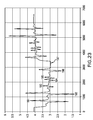
- FIG. 23 shows a plot of drag force against time generated by moving the strip of FIG. 22 in an apparatus according to the invention, first by moving the strip in one direction, and then, after a small pause, in the reverse direction.
- FIG. 24 shows a drag force plot for a “stack” of three strips all having the same nominal length and width dimensions and cut from the same sheet of material, in which the “middle” strip had purposefully instilled “defects”.
- This invention is based on the surprising discovery that the drag torque experienced during the process of magnetizing one or more polarized circumferential bands on a ferromagnetic shaft diminishes from its starting value during some number of shaft revolutions in close proximity to a (circumferentially) thin magnet. Magnetization of a polarized band on the shaft is determined to be complete when the drag torque stabilizes.
- FIG. 1 shows the physical arrangement used to magnetically polarize a circumferential band of width w and depth ⁇ on a ferromagnetic shaft ( 2 ) together with pertinent geometric factors.
- R represents the outside radius of the shaft
- G the gap between magnet ( 1 ) and shaft
- r the distance between any point “P” on the periphery of the shaft and the magnet center
- ⁇ the position angle for any point P measured in the CW direction starting from the magnet side.
- G 0.1 R.
- Analogous curves for other values of G/R have similar shapes, although the range of ⁇ where the visible portions of the curve reside diminishes with decreasing G/R.
- H c coercive force
- the local intensity and direction of magnetization are determined (more so for the circumferential component, less so for the radial component due to its large demagnetization factor) by these field characteristics, as indicated schematically in FIG. 4( a ). If the shaft slowly rotates, e.g., to the position shown in FIG. 4( b ), the local magnetization at points within the shaft near the surface will change continuously during passage through this active zone (AZ). H may well (as in FIG. 3) remain above H c throughout a direction change of at least 180°, and even 240° or more, while passing through the AZ.
- F max an upper limit for F, F max .
- the maximum drag force is seen to depend on just two dimensions in addition to (E h ) sat : w, determined by the magnet, and t, determined by the shaft construction.
- FIGS. 6 and 7 illustrate how drag force changes with cumulative shaft rotation angle.
- initial growth in the drag force results from the development of asymmetry in the distribution of M within the AZ, as shown in FIG. 4( b ).
- the direction of H changes smoothly within the AZ, although M is delayed by the energetic impediments to domain wall motion and anisotropy.
- This asymmetry grows during rotation up to the angular width of the AZ, and perhaps somewhat beyond as the penetration depth of M increases.
- the drag force grows during this rotational period.
- M c The demagnetizing field associated with the circumferential magnetization (M c ) that initially appears outside the AZ (see FIG. 8( a )) reduces the intensity of M c . This field diminishes as the region expands circumferentially with further shaft rotation (see FIG. 8( b )). Eventually this circumferential, but non-uniform, magnetization extends around to the beginning of the AZ (see FIG. 8( c )). Ever less limited by its own demagnetization, M c grows in both intensity and uniformity during subsequent shaft rotations. The orientation distribution of the field within the AZ, previously determined solely by the magnet, is altered by a new and growing field, primarily in the ⁇ H cir direction, from this magnetized “C” section.
- Example 2 describes a representative device useful for measuring the drag force on a variety of ferromagnetic shafts being magnetized with variety of different magnets spaced at different distances from the shaft.
- the sensors of the invention employ at least one measurement magnet and an operably associated sensing element used to detect force applied to the measurement magnet. Magnets and sensing element are described in the following sections.
- any suitable electromagnet or permanent magnet can be used as a measurement magnet, although magnets that produce consistent, uniform magnetic fields of known strength are preferred. Particularly preferred permanent magnets are NdFeB magnets.
- Individual measurement magnets may be used, as may measurement magnet arrays. Suitable magnet arrays include segmented arrays, staggered arrays, and segmented, staggered arrays. As will be appreciated, the measurement magnets in a given array may be configured so that the surface area that they collectively sweep is less than the sum of the surface areas that is swept by each of them. Alternatively, the surface area collectively swept by the measurement magnets may be equivalent to or greater than the surface areas that are swept by each of them when considered individually.
- any measurement or reference magnet, or array of measurement or reference magnets will vary depending upon the particular application.
- the design and selection of suitable magnets for a given application is well within the ordinary skill in the art.
- the sensing element operably associated with a measurement magnet outputs a signal that is indicative of the magnetic drag force experienced by the measurement magnet upon exposure to a ferromagnetic sample in motion (or having previously been in motion) relative to the measurement magnet.
- the task of measuring force resides primarily in sensor design, which can be resolved into two problems: geometric or physical constraints; and converting the force into a workable signal.
- an applied force can be measured many ways, including: by balancing the applied force against a standard mass through a system of levers; measuring the acceleration of a known mass and using Newton's second law; equalizing the applied force to a magnetic force generated by the interaction of a current-carrying coil and a magnet; distributing the applied force on a specific area to generate pressure, and then measuring the pressure; and converting the applied force into the deformation of an elastic element.
- force sensors useful for force-to-signal conversion are described. Any of these, as well as any other suitable now known or later developed force-to-signal measurement device, can be readily adapted for use in practicing this invention.
- a strain gauge load cell comprises a metal wire structure that elastically deforms when subjected to a force. As a member is stressed, the resulting strain deforms the strain gauge that is bonded (e.g., by cement or epoxy) or otherwise securely attached to the member. The resistance of the metal wires changes as it undergoes strain, which change in resistance is used by a strain gauge load cell to produce an electrical signal proportional to the deformation of the member. Small loads are commonly measured by beam-type strain gage load cells. Ring-type load cells cover a wider range of loads.
- piezoelectric crystals When a force is exerted on certain crystalline materials (i.e., piezoelectric crystals), electric charges are formed on the crystal surface in proportion to that force.
- a charge amplifier is required to integrate the electric charges to give a signal that is proportional to the applied force and large enough to measure.
- Sensors based on piezoelectric crystals differ from most other sensing techniques in that they are active sensing elements. No power supply is needed, and the deformation to generate a signal is very small, which has the advantage of a high frequency response of the measuring system without introducing geometric changes to the force-measuring path.
- Transducers that use capacitance variation can also be applied to measure force.
- the force is directed onto a plane whose elastic deflection is detected by a variation of the capacitance.
- Highly sensitive force transducers can be constructed because capacitive transducers accurately sense very small deflections.
- An electric circuit converts the capacitance variations into dc-voltage variations.
- Force-sensing resistors utilize the fact that certain polymer thick-film devices exhibit decreasing resistance with the increase of an applied force.
- a force-sensing resistor is made up of two parts. The first is a resistive material applied to a film. The second is a set of digitating contacts applied to another film. The resistive material completes the electrical circuit between the two sets of conductors on the other film. When a force is applied to such a sensor, a better connection is made between the contacts; hence, the conductivity is increased.
- Magnetostrictive transducer devices operate based on the Joule effect, which states that a ferromagnetic material is dimensionally altered when subjected to a magnetic field.
- the effect is reversible and used in magnetoelastic force sensors: if an external force produces a strain in a magnetostrictive material, the material's magnetic state changes proportionally to the applied stress. An electric circuit converts these magnetic state changes to a voltage signal for subsequent processing.
- Torsional balances are equal arm scale force measuring devices. They are comprised of horizontal steel bands instead of pivots and bearings. The principle of operation is based on force application on one of the arms that will deflect the torsional spring in proportion to the applied force.
- a hydraulic load cell is a device filled with a liquid (usually oil) that has a pre-load pressure. Application of a force to the loading member increases the fluid pressure, which is detected by a pressure transducer.
- a force is applied to one side of a piston or a diaphragm of flexible material and balanced by pneumatic pressure on the other side. This counteracting pressure is proportional to the applied force, and is detected by a pressure transducer.
- the magnetic drag force sensors of the invention will most frequently be integrated into a complete device for measuring magnetic drag force, i.e., a magnetic drag force measurement device.
- the magnetic drag force sensor(s) is positioned such that, in operation, the measurement magnet thereof is proximately spaced from a ferromagnetic sample capable of moving relative to the measurement magnet, such that the sensor, the sample, or both may be moved relative to one another during operation of the device.
- Signals output by the sensor are preferably conditioned by such suitable electronic circuitry as is required for the particular application, thus allowing it to be recorded, transmitted, and/or analyzed.
- the signals are digitized into a form suitable for use by a processor configured to process them in order to determine a parameter of the magnetic drag force experienced by the measurement magnet.
- the results of the processing may be stored in a storage device and/or output to an output device (for example, a plotter, a computer monitor) interfaced with the device.
- a device in order to move a magnetic drag force sensor and/or the ferromagnetic sample, a device according to the invention preferably includes a drive system adapted for the particular application. Moreover, for some applications (e.g., measurement of hysteresis loss), it is desirable to sufficiently magnetize the sample, preferably by placing it in a state of known remnant magnetization, prior to moving the sample relative to the magnetic drag force sensor. This may be accomplished through the use of one or more magnets positioned upstream of the measurement magnet(s) of magnetic drag force sensor. Alternatively, the sample may first be exposed to the measurement magnet in a non-sensing mode in order to establish the desired state of remanent magnetization. Thereafter, the sample can be moved relative to the magnetic drag force sensor so that the drag force can be measured. It will also be appreciated that a magnetic drag force may also be detected after stopping the relative motion of the magnetic drag force sensor and sample.
- a device of the invention may also include one or more magnets, including one or more measurement magnets disposed in one or more magnetic drag force sensors, positioned such that upon exposure to a sample, at least one measurement magnet is proximately spaced from a first surface of the sample and a second measurement magnet is proximately spaced from a second, different surface of the sample.
- one measurement magnet is positioned above and is proximately spaced from the upper surface of the sample, whereas the other measurement magnet is positioned below and is proximately spaced from the lower surface of the sample.
- a device can be adapted for detecting and/or measuring (qualitatively, semi-quantitatively, or quantitatively) magnetic drag forces in conjunction with ferromagnetic samples of any shape, size, or composition.
- Representative sample shapes include plates, bars, strips, wires, and cables. In cross-section, such samples may, for example, have a geometric shape selected from the group consisting of a circle, an ovoid shape, and a polygon (e.g., a triangle, rectangle, square, etc.).
- the device will be configured to analyze ferromagnetic samples of substantially uniform geometric cross-section, while in other embodiments, the devices will be configured to adapt to different sample sizes, shapes, etc. Samples may be separate pieces, or they may be one continuous piece.
- the device typically comprises a sample stage, or platform, upon which a ferromagnetic sample can be placed.
- One or more sensing elements are positioned so that they are operably associated with the sample stage.
- the sensing element also outputs signals indicative of a magnetic drag force, the difference being that drag force is experienced by the ferromagnetic sample upon exposure to a pre-determined magnetic field generated by one or more reference magnets (or a reference magnet array) proximately spaced from the ferromagnetic sample.
- the reference magnet or reference magnet array
- the reference magnet may be movable in relation to the sample stage (see FIG. 9 , sample stage not shown), for example, by placement of the reference magnet PM ( 26 ) on a carriage that allows controlled movement of the reference magnet (or reference magnet array). As shown in FIG.
- movement ( 25 ) of the reference magnet ( 26 ) about a carriage causes the sample ( 28 ) to experience a drag force ( 32 ), which can be sensed by the sensing elements (force sensor elements 30 and 31 ).
- the sample stage (not shown) is preferably made of a material that is non-magnetic. Similar embodiments, in which the reference magnet remains stationary and the sample stage is moved at a uniform speed, are also envisioned.
- NDE is typically incorporated into manufacturing processes in one of four primary ways: to provide quality control during manufacture or fabrication; to ensure that an item conforms to established specifications; to examine plant, equipment, or components during service, in order to meet regulatory requirements or to check for evidence of wear or premature failure; or as a diagnostic tool in research and development.
- FIG. 10 illustrates some of the numerous applications for the instant magnetic drag force sensors.
- the magnetic drag force sensors and devices of the invention can be used to measure hysteresis losses, thickness of material, material composition and/or microstructure, inhomogeneity or other defects (e.g., internal flaws, surface scratches, etc.) in samples, and correlated mechanical properties (e.g., hardness, strength, etc.).
- Such sensors and devices may also be used to determine a material's orientation (for example, by detecting the presence of non-visible features) and for identification purposes (for example, by detecting a coded arrangement of non-visible features).
- a material's orientation for example, by detecting the presence of non-visible features
- identification purposes for example, by detecting a coded arrangement of non-visible features.
- the particular context in which the method is to be performed determines the ultimate configuration of the device to be employed, although in each case they will be used to sense a detectable drag force parameter, such as a steady state, time rate of change of the drag force, etc.
- FIG. 11 Several general device configurations are schematically shown in FIG. 11 . Similar devices employing a single measurement magnet are described in detail in Example 1, below. In general, these devices employ at least one magnetic drag force sensor positioned near the surface of a ferromagnetic sample to be tested. The sensor comprises one or more measurement magnets spaced slightly from sample.
- the measurement magnet(s) is(are) operably associated with a force sensing element (e.g., a load cell) such that a drag force, or changes in the drag force, experienced by the measurement magnet(s) can be measured during or after the sensor and sample move in relation to each other.
- a force sensing element e.g., a load cell
- the sample is magnetized (i.e., “initialized”) before encountering the measurement magnet(s). Initialization ensures that the ferromagnetic sample enters the active zone (AZ) of the measurement magnet(s) in the desired state of magnetization.
- the sample For hysteresis loss measurement, the sample should enter the AZ of the measurement magnet(s) remanently magnetized with a polarity relative to the first encountered field of the measurement magnet(s), which depends on which loop area is to be measured.
- the device can be used for the measurement of the hysteresis loss associated with a major hysteresis loop.
- the device can be used for the measurement of the hysteresis losses associated with the combination of the major and minor hysteresis loops.
- the contribution of the minor hysteresis loop can be determined by using two measurement magnets, preferably one having its magnetic moment oriented parallel to the sample's direction of travel, the other, normal to the sample's direction of travel.
- both UM and MM will have their magnetic moments normal to the direction of motion and to the sample surface.
- the UM and MM have the same polarity orientation.
- the leading edge of the SUT enters the AZ of the UM, it is subjected first to an increasingly intense field of one polarity, followed by a decrease in intensity and, after crossing zero, to an increasing field of the opposite polarity, followed by a decrease towards zero as it recedes from the AZ.
- the SUT thus leaves the AZ of the UM in a remanent magnetic state.
- the leading edge of the SUT enters the AZ of the MM, it first encounters an increasingly intense field of opposite polarity to its remanence.
- the use of one or more magnets (CUM ( 39 ) and CMM ( 38 )) positioned below the SUT ( 36 ) and opposite the corresponding magnet(s) ( 37 and 35 , respectively) disposed proximate to the opposite surface of the SUT can provide compensating attractive forces.
- the drag force on the CMM may also be measured and added to the drag force measured on the MM.
- the MM and CMM may be physically connected to the same force measurement system.
- embodiments that reduce the attractive force between measurement and/or upstream magnets and the sample being tested may simplify the magnet support system and prevent distortion of thin SUTs. Such configurations will also reduce the intensity of field components normal to the direction of motion, thereby more nearly reproducing the uniaxial fields used in conventional hysteresis loss measurement systems.
- one or more upstream magnets may be employed to “initialize” a ferromagnetic sample, i.e., place it into a desired state of remanent magnetization.
- initialization can also be achieved by bidirectional motion of the sample in relation to the measurement magnet.
- the magnetic moment of the measurement magnet will preferably be disposed parallel or normal, depending upon application, to the direction of motion of the sample, and combinations of measurement magnets wherein the magnetic moment of one is oriented normal to, and another is oriented such that its magnetic moment is oriented parallel to, the sample's direction of motion, can also be used.
- one or more magnets placed on opposite sides of the sample can serve to reduce or eliminate the attractive force.
- Another series of applications for the sensors and devices of the invention is in the context of detecting inhomogeneity and defects in ferromagnetic materials for various shapes and sizes, from small strips of materials to large plates, wires, cables, bars, etc. These methods may be applied during manufacturing processes, or in the field, for example, to test for wear and fatigue of structurally critical components.
- one or more markers that disrupt the homogeneity of some portion of a ferromagnetic material may be intentionally introduced in order to provide a “signature” that enables the material to be identified, its orientation to be determined, etc.
- markers can be introduced into a sample, for example, by heat-treating small areas of the sample at specific locations, preferably in a specific pattern that can later be detected in a signal obtained by measuring magnetic drag force in at least the region(s) where the marker was earlier introduced.
- markers include shot peening, etching, scratching, or otherwise scoring a surface, forming one or more holes or cavities in the material, introducing an inhomogeneity into one or more specific locations in a material during the manufacturing process (e.g., by emplacing materials having chemical compositions or properties that differ from the material from which the sample is otherwise formed), etc. Indeed, any method suitable for the introduction of a flaw or defect that locally alters a magnetic property of the material can be used for this purpose.
- Yet another application for this instant invention is the context of monitoring manufacturing processes, even in real time. For example, by monitoring magnetic drag force during a production process, material homogeneity can be assessed, as can material quality.
- the instant invention can be used to monitor whether a particular production process, or portions thereof, is functioning properly. For example, if a ferromagnetic material produced by a rolling, stamping, or other forming process is required to have a certain degree of surface smoothness, for example, use of a device according to the invention can be used to monitor that metric (here, degree of surface smoothness), and also to detect, for example, when a roller upstream of the drag force measurement sensor may be damaged or worn, whether some portion of the stamping surface of a tool has become damaged or worn, etc.
- metric here, degree of surface smoothness
- This example describes one preferred embodiment of the invention.
- the force resisting the motion of a ferromagnetic member through the intense field close to a permanent magnet is measured by the equal and opposite reaction force on the permanent magnet. This force tends to “drag” the magnet in the direction of motion of the ferromagnetic member.
- FIGS. 12( a ) and ( b ) Photographs of apparatus incorporating this embodiment is shown in FIGS. 12( a ) and ( b ). The essential features are depicted in the schematic diagram of FIGS. 13 ( a ) and ( b ).
- the drag force measuring device ( 90 ) employs a single permanent magnet (PM; 100 ) suspended at the distal end ( 102 ) of a pendulum ( 104 ) which can rotate freely about shaft ( 108 ).
- the pendulum is biased to bear slightly against the load cell ( 110 ) in the absence of any drag (tangential) force on the magnet. This bias prevents the pendulum from losing contact with the load cell.
- the output signal of the load cell is generally fed through a cable to a meter, recorder, and/or data acquisition system (not shown), as required.
- the ferromagnetic sample under test, SUT here shown as a strip ( 106 )
- the SUT ( 106 ) is driven in the directions shown ( 112 ) by any suitable means, here shown as rollers ( 114 ).
- the actual value of drag force is determined as one-half the difference between the output forces measured while the strip ( 106 ) moves first in one direction, then the other. In this way, there is no need to know the actual value of the deliberately applied bias force, nor do any unknown biasing influences affect the measurement accuracy.
- FIG. 14 A typical plot of the output signal from the load cell as a cold rolled steel strip sample (25.5 mm wide, 1.63 mm thick and 300 mm long) was moved first in one direction, then, after a brief pause, in the other direction, is shown in FIG. 14 .
- the speed of motion of the SUT for this plot was approximately 4 mm/s.
- the dimensions of the measurement magnet were 50.8 mm by 12.7 mm by 3.175 mm, and the magnetic moment was assumed to be approximately 1920 ergs/gauss.
- FIG. 5 A schematic diagram of the apparatus is illustrated in FIG. 5 .
- the shaft was made out of 300M steel (0.43% C, 1.8% Ni, 1.6% Si, 0.8% Cr, 0.4% Mo, 0.07% V, Bal Fe) with an outside radius, R, of 17.5 mm and a wall thickness, t, of 2.5 mm.
- the coercive force of the material is ⁇ 39 Oe.
- the measurement magnet was of NdFeB type with an energy product of 38MGO, and had dimensions of 2 in. by 0.5 in. by 0.125 in.
- the load cell was manufactured by Futek (model L2338).
- the shaft was rotated at slow speed (16.6 rpm) by coupling to a synchronous gear head motor and at high speed (2000 rpm) with a variable speed motor using an O-ring belt.
- Measured values of the drag force for the first 22 revolutions of the shaft are shown in FIG. 6 for a variety of gaps between the magnet and the shaft surface.
- a similar plot for a variety of magnet sizes is shown in FIG. 7 .
- a polarizing magnet experiences a reaction force that is equal in amplitude to the drag force on a ferromagnetic shaft being magnetized. Such an apparatus can measure this force using a wide range of shaft sizes.
- the drag force develops during the early part of the first revolution, reaches a peak before the end of that revolution, and diminishes thereafter to a stable value within 5-10 complete shaft revolutions.
- drag force measurement can be employed to determine when in this process for instilling a circumferentially magnetized band within a shaft that magnetization has reached a stable value.
- the data also demonstrates that the drag force stabilizes sooner and at higher values with smaller gaps between the magnetization magnet and the shaft.
- FIG. 7 also shows that the limiting value of drag force increases somewhat more quickly than magnet width, reflecting the greater average field intensity developed by wider magnets. At rotational speeds of greater than about 40 rpm, the final drag force values started to grow continuously with increasing speed, an expected consequence of eddy currents.
- This example describes another preferred embodiment, wherein a magnetic drag force measurement device according to the invention (as schematically illustrated in FIG. 15 ) is used to measure hysteresis loss in a ferromagnetic strip.
- a magnetic drag force measurement device according to the invention (as schematically illustrated in FIG. 15 ) is used to measure hysteresis loss in a ferromagnetic strip.
- this example also describes novel methods for determining hysteresis losses, particularly in thin strips of soft magnetic materials. These methods are based on the measurement of a drag force that arises with movement of a thin sample strip through the strong field existing in the space near a measurement magnet (here, a permanent magnet). Not associated with macro eddy currents, the drag force is shown to originate from the magnetic hysteresis of the material, having in fact an amplitude equal to the product of hysteresis loss and the area of the sample cross section. Correlation within 18% with measurements made by conventional methods is shown for a wide
- Hysteresis loss is a defining characteristic of electrical steels, and strongly influences the energy efficiency and functionality of the products in which such materials are used. Hysteresis loss varies greatly with the elemental composition of the particular steel, the thermal and mechanical fabrication processes used to produce the steel, and the direction of magnetization (Dupre, et al. (2000), J. Magn. Mag. Mat., vol. 215, p. 112). Hysteresis loss measurement, therefore, is routinely practiced both during the development of such materials and to ensure the consistent quality of finished products.
- the specimen under test, or SUT ( 130 ) is maintained at a small, fixed distance ( 135 ), from a magnetic dipole of moment, m, typically a permanent measurement magnet, PM ( 132 ). Both the SUT ( 130 ) and the PM ( 132 ) are constrained to disallow the mutual attractive force, F a , to bring them into contact.
- the SUT ( 130 ) is made to move in a direction parallel to m at some convenient, not necessarily constant, velocity, but slowly enough to avoid the corrupting influence of eddy currents.
- PM is assumed to be a single dipole.
- the SUT though having a finite cross sectional area, A, is assumed to have negligible dimensions normal to m and, in the plane of its surface facing PM, normal to the direction of motion.
- H the intensity of the dipole field
- the SUT is also assumed to extend far enough in both longitudinal directions so that its ends are situated in regions of vanishingly small H.
- H includes components normal to m, the shape anisotropy of the SUT limits the effects of these components on the magnetization orientation.
- H H at a point P within the SUT, at a distance Gx from the central location of m, is readily shown to be:
- Equations (9a) and (9b) show H L to depend only on m, G and the normalized distance, x, to P.
- H L is symmetrical around x.
- the peak negative H L is 20.2% of its peak positive value, H p+ , and occurs at 1.225 G.
- the SUT is assumed to have arrived at the position shown in FIG. 15 by motion from left to right, and that in so doing, at least the portion shown, passed under a second, identical PM (PM 2 —not shown), also separated from the SUT by G, and located greater than 12 G upstream (in the device illustrated in FIG. 15 , to the left of PM) of the permanent measurement magnet.
- PM PM 2
- An element of material of infinitesimal length, dx, at position 1 in FIG. 16 a while presently located where the fields from both permanent magnets (PM 1 and PM 2 ) are near zero, will previously have been exposed to the peak negative field, H p ⁇ , from PM 2 , assumed to be sufficient to result in technical saturation.
- this element of material when reaching position 1 , the start of the AZ, this element of material will be at negative remanence, ⁇ M r , indicated as point 1 on the hysteresis loop in FIG. 16 b , and transcribed to a plot of M vs. x in FIG. 16 c .
- ⁇ M r negative remanence
- a distance sufficient for the element originally at 1 to arrive at 2 the location of H p ⁇ , M within this element will grow along the path indicated 1 ⁇ 2 in FIG. 16 b and 16 c .
- H L falls to zero and M returns to ⁇ M r along path 2 ⁇ 3 ( FIG.
- FIG. 16 f shows the cumulative sum of the elemental forces to the left of each point within the AZ.
- the existence of a finite final sum, F as clearly shown in FIG. 16 f , reflects the asymmetry of the plots in FIGS.
- the magnetic drag force measurement device used to conduct these experiments was essentially the same device as described in Example 1. Also, the device was modified to hold the sample strip at fixed distances ranging from between 0.25 mm and 5.1 mm under the pendulum mounted measured magnet, and it was equipped with a small gear head motor and driving rollers that allowed the sample strip to be moved in either horizontal direction at speeds ranging from 1.6 to 7 mm/s.
- the measurement magnet was a 50.8 mm long (and thus extended well beyond the edges of the narrower sample strips), 12.7 mm wide (normal to the strip surface), and 3.17 mm thick (longitudinal).
- the samples were first moved back and forth such that the central 250 mm of each 280 mm strip passed once in each direction under the measurement magnet. This ensured that all portions of a strip not in the AZ were placed in the (negative) remanent state without the need for a second magnet upstream of the measurement magnet.
- Each sample strip was then positioned to allow the central 80 mm to pass once in each direction under the measurement magnet while the horizontal force on the magnet was measured and recorded. Forward and reverse motions were used to eliminate the effect of possible components of the attractive force due to imperfect parallelism between m and the direction of sample strip motion.
- the pendulum was biased to always exert a force in one direction on the load cell; F d then being taken as 0.5 ⁇ the difference between the average forces measured in each direction. Limiting the measurements to a relatively small central region of the SUT prevented its ends from getting close enough to the measurement magnet to develop significant parasitic forces.
- Quasistatic hysteresis loss associated with both major and minor loops was measured in a double yoke, small size single sheet tester (SST)(De Wulf, et al. (2003), J. Magn. Magn. Mat., vol. 254, p. 70) using a current mode excitation with a constant dH/dt of 1 (kA/m)/s.
- SST small size single sheet tester
- Major and minor B-H loops for the 3 Si-steel samples are shown in FIG. 17 , with similar loops for the blackened nickel and a low carbon steel, in both cold-rolled and annealed conditions, shown in FIG. 18 .
- the results of both conventional and magnetic drag force measurements are listed in Table 1, above.
- FIG. 19 shows the effect of varying the spacing between measurement magnet and the various sample strips. As these results show, the magnetic drag force initially increases with decreasing gap for all of the test specimens, with all except strip Z reaching limiting values near 1 mm gaps. The data scatter seen for this sample strip suggests that the accurate measurement of very low drag forces (about 1.1 mN) may be beyond the capability of the load cell (5 N range) utilized.
- Hysteresis losses determined by magnetic drag force measurement was seen to match within 18% those determined by a conventional method.
- This unexpectedly close correlation for materials having a wide range of magnetic and geometric characteristics indicates that neither normal field components nor the demagnetizing fields arising from the large values of dM/dx (FIG. 16 ⁇ ) existing within some portions of the active zone have significant effects.
- the sluggish dependence on gap was also not unexpected, since peak field excursions of just a few times the coercivity are usually sufficient to develop the major portion of major loop areas.
- This example provides a description of a preferred embodiment of the invention that can be used, for example, to detect defects in large plates. See FIG. 20 .
- This device ( 150 ) is a small three-wheeled ( 152 ) machine that can be propelled manually by pushing on the handles ( 154 ).
- the magnetic drag force sensor is housed within a cavity ( 157 ) in the body of the device ( 150 ).
- the magnetic drag force sensor has a pendulum ( 159 ) that holds a measurement magnet ( 156 ), which is disposed at the bottom end of the pendulum ( 159 ).
- Two sensing elements ( 170 ) engage the pendulum ( 159 ), which can pivot about a shaft ( 160 ). As this device is moved at a uniform speed across a large ferromagnetic surface (e.g., a submarine hull), changes in the magnetic drag force can be sensed.
- a large ferromagnetic surface e.g., a submarine hull
- This example provides a description of a preferred embodiment of the invention that can be used, for example, to detect flaws in a cable, for example, a ski-lift cable. See FIG. 21 .
- the cable ( 180 ) passes through a stationary magnetic drag force sensor ( 182 ) that comprises a ring magnet ( 184 ) operably associated with two force sensing elements ( 186 , 188 ).
- flaws in the cable can be detected in real-time.
- FIG. 22 shows a strip of low carbon steel in which various “defects” were purposefully instilled.
- the figure shows the dimensions of the strip and the locations and dimensions of three drilled holes ( 193 , 194 , and 195 ) and three abrasively cut slots ( 191 , 192 , and 196 ).
- the holes went completely through the strip, while the slots had a maximum depth of 0.30 mm (80%) of the strip thickness.
- FIG. 23 shows a plot of the drag force against time (hence of position along the strip), as the strip was moved first in one direction, and then, after a small pause ( 197 ), in the reverse direction, between a pair of identical measurement magnets (while held at a small constant distance below a measurement magnet) mounted in the previously described apparatus.
- the variation in drag force with position clearly shows both the relative size and location of the instilled defects ( 191 - 196 ).
- the portions of the plot on the left side of the paused region are seen to closely mirror those on the right side of this region, with the variations in drag force on each side clearly reflecting the defects instilled in the strip.
- the magnitude of the drag force associated with each defect is seen to have a sharp decrease (or increase) followed by a similarly sharp increase (or decrease).
- These changes in drag force are believed to arise from the magnetic poles that form at the longitudinal extremes of each defect in response to the inhomogeneous magnetization existing between the bulk of the strip and the regions within the defects where the material is absent.
- a north or south pole will form at one end of the defect and an opposite pole will form at the other.
- the repulsive force between the upstream pole of the measurement magnet and the approaching pole from the defect is the source of the first occurring drag force peak and the repulsive force between the downstream pole of the measurement magnet and the receding pole from the defect is the source of the second occurring peak.
- the vertical displacement of the two regions of the plot shown in FIG. 23 is indicative of the magnetic hysteresis loss of the strip being tested.
- FIG. 24 shows the drag force plot for this “stack” of strips when tested in the same apparatus, and in the same manner as the previously described defect-containing strip.
Landscapes
- Physics & Mathematics (AREA)
- Condensed Matter Physics & Semiconductors (AREA)
- General Physics & Mathematics (AREA)
- Force Measurement Appropriate To Specific Purposes (AREA)
- Investigating Or Analyzing Materials By The Use Of Magnetic Means (AREA)
Abstract
Description
r=[(R+G)2 +R 2−2(R+G)R cos α]1/2 (1)
φ=tan−1(0.5 tan θ) (2)
θ=π/2−sin−1(R sin α/r) (3)
Although a real polarizing magnet comprises a 3-dimensional distribution of magnetic dipoles, it can be represented as a single equivalent dipole of magnetic moment m. Thus, the intensity of the field H at any point P on the periphery of the shaft in the plane of m can be determined using the formula:
H cir =H cos(α−θ−φ)
H rad =H sin(α−θ−φ) (5)
W h =w2π∫0 E h(R−p)dp. (6)
This hysteretic energy is supplied by the mechanical work expended during each revolution: Wm=2πT, where T is the torque required to rotate the shaft. T is produced by the tangential component of force, F=T/R, originating from the magnetostatic interaction between the magnet and the “poles” associated with the asymmetrical ∇●M within the AZ. Equating Wh and Wm and replacing T by FR yields the equation:
2πFR=w2π∫0 E h(R−p)pdp. (7)
F max =wt(E h)sat. (8)
-
- i. Strain Gauge Load Cells
-
- iii. Capacitive Force Transducers
-
- iv. Force-Sensing Resistors (Conductive Polymers)
-
- vi. Torsional Balances
-
- vii. Hydraulic Load Cells
-
- viii. Pneumatic Load Cells
directed at an angle, β=tan−1(0.5/x)+tan−1(1/x), to m. Its longitudinal component is then found from
Equations (9a) and (9b) show HL to depend only on m, G and the normalized distance, x, to P.
Since the AZ contains elements having magnetizations representative of traversal of both the
4. Experiments.
| TABLE 1 |
| Identification of materials tested, together with measurement results and correlation assessment. |
| ID | Material | Condition | Thickness | Major | Minor | Minor/Major | Major + Minor | By Fd | Diff. % |
| A | Black Nickel | As Rec'd | 0.254 mm | 992.8 J/m3 | 80.6 J/m3 | 8.11% | 1073.4 J/m3 | 1037.0 J/m3 | −3.4 | |
| B | AISI1010 Steel | Cold Rolled | 0.127 | 5450.4 | 698.0 | 12.81 | 6148.4 | 6336.2 | 3.1 | |
| C | AISI1010 Steel | Annealed | 0.125 | 1450.1 | 285.2 | 19.67 | 1735.3 | 1952.3 | 12.5 | |
| D | AISI1010 Steel | Cold Rolled | 0.254 | 6317.3 | 492.1 | 7.79 | 6809.4 | 6798.6 | −0.2 | |
| E | AISI1010 Steel | Annealed | 0.250 | 1240.1 | 59.7 | 4.81 | 1299.8 | 1324.9 | 1.9 | |
| F | AISI1010 Steel | Cold Rolled | 0.381 | 6745.1 | 744.8 | 11.04 | 7489.9 | 7137.0 | −4.7 | |
| G | AISI1010 Steel | Annealed | 0.370 | 1439.8 | 198.2 | 13.77 | 1638.0 | 1393.6 | −14.9 | |
| X | FeSi NO | 0.500 | 505.5 | 124.7 | 24.67 | 630.2 | 518.2 | −17.8 | ||
| Y | FeSi GO 75 deg | 0.235 | 372.4 | 173.3 | 46.54 | 545.7 | 531.9 | −2.5 | ||
| | FeSi GO | 0 deg | 0.288 | 155.3 | 39.2 | 25.24 | 194.5 | 199.5 | 2.6 | |
Claims (22)
Priority Applications (2)
| Application Number | Priority Date | Filing Date | Title |
|---|---|---|---|
| US11/588,983 US7437942B2 (en) | 2005-10-30 | 2006-10-27 | Non-destructive evaluation via measurement of magnetic drag force |
| US12/235,157 US20090013794A1 (en) | 2005-10-30 | 2008-09-22 | Non-destructive evaluation via measurement of magnetic drag force |
Applications Claiming Priority (2)
| Application Number | Priority Date | Filing Date | Title |
|---|---|---|---|
| US73188205P | 2005-10-30 | 2005-10-30 | |
| US11/588,983 US7437942B2 (en) | 2005-10-30 | 2006-10-27 | Non-destructive evaluation via measurement of magnetic drag force |
Related Child Applications (1)
| Application Number | Title | Priority Date | Filing Date |
|---|---|---|---|
| US12/235,157 Continuation US20090013794A1 (en) | 2005-10-30 | 2008-09-22 | Non-destructive evaluation via measurement of magnetic drag force |
Publications (2)
| Publication Number | Publication Date |
|---|---|
| US20070125182A1 US20070125182A1 (en) | 2007-06-07 |
| US7437942B2 true US7437942B2 (en) | 2008-10-21 |
Family
ID=38117401
Family Applications (2)
| Application Number | Title | Priority Date | Filing Date |
|---|---|---|---|
| US11/588,983 Expired - Fee Related US7437942B2 (en) | 2005-10-30 | 2006-10-27 | Non-destructive evaluation via measurement of magnetic drag force |
| US12/235,157 Abandoned US20090013794A1 (en) | 2005-10-30 | 2008-09-22 | Non-destructive evaluation via measurement of magnetic drag force |
Family Applications After (1)
| Application Number | Title | Priority Date | Filing Date |
|---|---|---|---|
| US12/235,157 Abandoned US20090013794A1 (en) | 2005-10-30 | 2008-09-22 | Non-destructive evaluation via measurement of magnetic drag force |
Country Status (1)
| Country | Link |
|---|---|
| US (2) | US7437942B2 (en) |
Cited By (2)
| Publication number | Priority date | Publication date | Assignee | Title |
|---|---|---|---|---|
| US20100301846A1 (en) * | 2009-06-01 | 2010-12-02 | Magna-Lastic Devices, Inc. | Magnetic speed sensor and method of making the same |
| US9063190B2 (en) | 2011-09-02 | 2015-06-23 | Ivan GARSHELIS | Magnetostatic measurement method and sensor for assessing local hysteresis properties in ferromagnetic materials |
Families Citing this family (12)
| Publication number | Priority date | Publication date | Assignee | Title |
|---|---|---|---|---|
| JP2010531993A (en) * | 2007-07-02 | 2010-09-30 | ステオルン リミテッド | Apparatus and method for measuring energy in magnetic interaction |
| WO2013014481A1 (en) * | 2011-07-26 | 2013-01-31 | Arcelormittal Investigación Y Desarrollo Sl | Hot-formed previously welded steel part with very high mechanical resistance, and production method |
| US20130287508A1 (en) | 2012-04-25 | 2013-10-31 | Milwaukee Electric Tool Corporation | Magnetic drill press |
| US20140188148A1 (en) * | 2012-12-27 | 2014-07-03 | Pieter W.C.J. le Blanc | Surgical tunneler |
| US9665932B2 (en) * | 2013-09-03 | 2017-05-30 | Thales Transport & Security, Inc. | Camera based cable inspection system |
| EP3411173B1 (en) | 2016-02-01 | 2022-11-16 | Milwaukee Electric Tool Corporation | Holding force detection for magnetic drill press |
| EP3438657A1 (en) * | 2017-08-02 | 2019-02-06 | Eddyfi NDT Inc. | Device for pulsed eddy current testing of ferromagnetic structures covered with ferromagnetic protective jacket |
| CN109031170B (en) * | 2018-08-13 | 2023-12-22 | 苏州佳祺仕软件技术有限公司 | Product placement mechanism for small magnet suction testing equipment |
| CN111089896B (en) * | 2019-12-13 | 2021-12-14 | 清华大学 | Magnetically excited isotropic defect contour imaging device and imaging method |
| US11577503B2 (en) * | 2021-02-17 | 2023-02-14 | Xerox Corporation | Fountain solution thickness control system in a digital printing device using a drag force sensor |
| CN113213823B (en) * | 2021-04-26 | 2022-08-09 | 哈尔滨工业大学 | Magnetic cement mortar damage detection sensor and manufacturing method and application thereof |
| CN119619270B (en) * | 2024-12-16 | 2025-09-23 | 山东大学 | Metal material nondestructive testing device adopting soft magnetic stripe and application method |
Citations (14)
| Publication number | Priority date | Publication date | Assignee | Title |
|---|---|---|---|---|
| US2398574A (en) * | 1945-02-23 | 1946-04-16 | John M Bell | Drag testing apparatus |
| US2731025A (en) * | 1954-08-31 | 1956-01-17 | Foxboro Co | Magnetic drag speed measurement device |
| US3225605A (en) * | 1959-09-30 | 1965-12-28 | North American Aviation Inc | Eddy current induction device |
| US3513386A (en) * | 1965-09-10 | 1970-05-19 | Philips Corp | Contact-free speed measuring instruments |
| US3517894A (en) * | 1967-10-09 | 1970-06-30 | Edwin A Pauls | Device for creating tension in a travelling strip |
| US3717103A (en) * | 1970-12-11 | 1973-02-20 | North American Rockwell | Low drag magnetic suspension system |
| US3863501A (en) * | 1973-12-19 | 1975-02-04 | Honeywell Inc | Magnetostrictive sensor for a flowmeter |
| US3892185A (en) * | 1970-12-11 | 1975-07-01 | Rockwell International Corp | Low drag magnetic suspension system |
| US4915318A (en) * | 1985-09-26 | 1990-04-10 | John Lysaght (Australia) Limited | Electromagnetic drag mechanisms for ferrous strip |
| US4950988A (en) * | 1988-02-11 | 1990-08-21 | Garshelis Ivan J | Two region, remanently magnetized position sensor |
| US5206469A (en) * | 1990-07-16 | 1993-04-27 | Sensor Technology Co., Ltd. | Crash sensor |
| US5367257A (en) * | 1992-05-14 | 1994-11-22 | Garshelis Ivan J | Non-contact, magnetic sensor for determining direction of motion and velocity of a movable member |
| US6725982B2 (en) * | 2000-02-10 | 2004-04-27 | Sumitomo Metal Industries, Ltd. | Eddy current braking apparatus |
| US7030603B2 (en) * | 2003-08-21 | 2006-04-18 | Micron Technology, Inc. | Apparatuses and methods for monitoring rotation of a conductive microfeature workpiece |
Family Cites Families (5)
| Publication number | Priority date | Publication date | Assignee | Title |
|---|---|---|---|---|
| US2593646A (en) * | 1946-07-25 | 1952-04-22 | Kollsman Instr Corp | Magnetic drag tachometer |
| US4405872A (en) * | 1978-09-07 | 1983-09-20 | Thomas Stephen E | Method and apparatus for generating electrical energy from the rotation of a wheel |
| DE3426784A1 (en) * | 1984-07-20 | 1986-01-30 | Bosch Gmbh Robert | MAGNETORESISTIVE SENSOR FOR DELIVERING ELECTRICAL SIGNALS |
| US4631959A (en) * | 1984-12-14 | 1986-12-30 | Metrex Instruments Ltd. | Drag anemometer |
| US4646557A (en) * | 1986-02-28 | 1987-03-03 | Kavilco Corporation | Dynamic force measurement system |
-
2006
- 2006-10-27 US US11/588,983 patent/US7437942B2/en not_active Expired - Fee Related
-
2008
- 2008-09-22 US US12/235,157 patent/US20090013794A1/en not_active Abandoned
Patent Citations (14)
| Publication number | Priority date | Publication date | Assignee | Title |
|---|---|---|---|---|
| US2398574A (en) * | 1945-02-23 | 1946-04-16 | John M Bell | Drag testing apparatus |
| US2731025A (en) * | 1954-08-31 | 1956-01-17 | Foxboro Co | Magnetic drag speed measurement device |
| US3225605A (en) * | 1959-09-30 | 1965-12-28 | North American Aviation Inc | Eddy current induction device |
| US3513386A (en) * | 1965-09-10 | 1970-05-19 | Philips Corp | Contact-free speed measuring instruments |
| US3517894A (en) * | 1967-10-09 | 1970-06-30 | Edwin A Pauls | Device for creating tension in a travelling strip |
| US3892185A (en) * | 1970-12-11 | 1975-07-01 | Rockwell International Corp | Low drag magnetic suspension system |
| US3717103A (en) * | 1970-12-11 | 1973-02-20 | North American Rockwell | Low drag magnetic suspension system |
| US3863501A (en) * | 1973-12-19 | 1975-02-04 | Honeywell Inc | Magnetostrictive sensor for a flowmeter |
| US4915318A (en) * | 1985-09-26 | 1990-04-10 | John Lysaght (Australia) Limited | Electromagnetic drag mechanisms for ferrous strip |
| US4950988A (en) * | 1988-02-11 | 1990-08-21 | Garshelis Ivan J | Two region, remanently magnetized position sensor |
| US5206469A (en) * | 1990-07-16 | 1993-04-27 | Sensor Technology Co., Ltd. | Crash sensor |
| US5367257A (en) * | 1992-05-14 | 1994-11-22 | Garshelis Ivan J | Non-contact, magnetic sensor for determining direction of motion and velocity of a movable member |
| US6725982B2 (en) * | 2000-02-10 | 2004-04-27 | Sumitomo Metal Industries, Ltd. | Eddy current braking apparatus |
| US7030603B2 (en) * | 2003-08-21 | 2006-04-18 | Micron Technology, Inc. | Apparatuses and methods for monitoring rotation of a conductive microfeature workpiece |
Non-Patent Citations (5)
| Title |
|---|
| Cullity, "Introduction to Magnetic Materials," Addison-Wesley, Reading, MA, Appendix 4:614-616 (1972). |
| De Wulf et al., "Comparison of methods for the determination of dc-magnetic properties of laminated SiFe alloys," J. Appl. Phys., 93(10):8543-8545 (2003). |
| De Wulf et al., "Design and calibration aspects of small size single sheet testers," J. Magn. Magn. Mat., 254-255:70-72 (2003). |
| De Wulf et al., "Quasistatic measurements for hysteresis modeling," J. Appl. Phys., 87(9):5239-5241 (2000). |
| Dupré et al., "Loss versus cutting angle in grain-oriented Fe-Si laminations," J. Magn. Magn. Mat., 215-216:112-114 (2000). |
Cited By (2)
| Publication number | Priority date | Publication date | Assignee | Title |
|---|---|---|---|---|
| US20100301846A1 (en) * | 2009-06-01 | 2010-12-02 | Magna-Lastic Devices, Inc. | Magnetic speed sensor and method of making the same |
| US9063190B2 (en) | 2011-09-02 | 2015-06-23 | Ivan GARSHELIS | Magnetostatic measurement method and sensor for assessing local hysteresis properties in ferromagnetic materials |
Also Published As
| Publication number | Publication date |
|---|---|
| US20070125182A1 (en) | 2007-06-07 |
| US20090013794A1 (en) | 2009-01-15 |
Similar Documents
| Publication | Publication Date | Title |
|---|---|---|
| US20090013794A1 (en) | Non-destructive evaluation via measurement of magnetic drag force | |
| Qiu et al. | Characterization of applied tensile stress using domain wall dynamic behavior of grain-oriented electrical steel | |
| JPH0658345B2 (en) | Non-contact detection method and detector | |
| JP2003529069A (en) | Magnetic base / force / torque sensor | |
| Kosmas et al. | The effect of magnetic anomaly detection technique in eddy current non-destructive testing | |
| Ducharne et al. | Directional magnetic Barkhausen noise measurement using the magnetic needle probe method | |
| Venkatachalapathi et al. | Characterization of fatigued steel states with metal magnetic memory method | |
| Stupakov et al. | Magnetic anisotropy of plastically deformed low-carbon steel | |
| Rękas et al. | A measuring setup for testing the mechanical stress dependence of magnetic properties of electrical steels | |
| Buttle | Magnetic methods | |
| WO2007053519A2 (en) | Non-destructive evaluation via measurement of magnetic drag force | |
| Jagadish et al. | The effect of stress and magnetic field orientation on surface Barkhausen noise in pipeline steel | |
| CN115031893A (en) | Calibration method for detecting residual stress field based on magnetic anisotropy | |
| Stupakov et al. | Alternative magnetic parameters for characterization of plastic tension | |
| Liu et al. | Stray flux effects on the magnetic hysteresis parameters in NDE of low carbon steel | |
| Zhang et al. | Study on stress testing of ferromagnetic materials based on magnetic anisotropy | |
| JPS59112257A (en) | Method and device for nondestructive inspection of ferromagnetic material | |
| Piotrowski et al. | Stress anisotropy characterisation with the help of Barkhausen effect detector with adjustable magnetic field direction | |
| JPH0141217B2 (en) | ||
| Gorkunov et al. | Effect of the Crystallographic Texture Type on the Anisotropy of the Magnetic Leakage Field Parameters of Steel Sheets | |
| CN116299094B (en) | A method for measuring the initial tensor magnetic permeability of plate-shaped samples | |
| Zhang | Micromagnetic and Multiparameter Measurement for Microstructural Material Properties Characterization | |
| Westwood et al. | Non-Contacting Bi-Axial Strain Measurement Method on Steel Pipeline | |
| Chady et al. | Data fusion from multidirectional remanent flux leakage transducers for nondestructive testing of stress-and fatigue-loaded steel samples | |
| Ren et al. | Experimental study of alternating current stress measurement under a uniaxial stress |
Legal Events
| Date | Code | Title | Description |
|---|---|---|---|
| AS | Assignment |
Owner name: MAGCANICA, INC., CALIFORNIA Free format text: ASSIGNMENT OF ASSIGNORS INTEREST;ASSIGNORS:GARSHELIS, IVAN J.;TOLLENS, STIJN P.L.;REEL/FRAME:019451/0806;SIGNING DATES FROM 20070215 TO 20070216 |
|
| STCF | Information on status: patent grant |
Free format text: PATENTED CASE |
|
| FPAY | Fee payment |
Year of fee payment: 4 |
|
| FEPP | Fee payment procedure |
Free format text: PAYOR NUMBER ASSIGNED (ORIGINAL EVENT CODE: ASPN); ENTITY STATUS OF PATENT OWNER: SMALL ENTITY |
|
| FPAY | Fee payment |
Year of fee payment: 8 |
|
| FEPP | Fee payment procedure |
Free format text: MAINTENANCE FEE REMINDER MAILED (ORIGINAL EVENT CODE: REM.); ENTITY STATUS OF PATENT OWNER: SMALL ENTITY |
|
| LAPS | Lapse for failure to pay maintenance fees |
Free format text: PATENT EXPIRED FOR FAILURE TO PAY MAINTENANCE FEES (ORIGINAL EVENT CODE: EXP.); ENTITY STATUS OF PATENT OWNER: SMALL ENTITY |
|
| STCH | Information on status: patent discontinuation |
Free format text: PATENT EXPIRED DUE TO NONPAYMENT OF MAINTENANCE FEES UNDER 37 CFR 1.362 |
|
| FP | Lapsed due to failure to pay maintenance fee |
Effective date: 20201021 |