US7434846B2 - Quick coupling - Google Patents
Quick coupling Download PDFInfo
- Publication number
- US7434846B2 US7434846B2 US11/117,887 US11788705A US7434846B2 US 7434846 B2 US7434846 B2 US 7434846B2 US 11788705 A US11788705 A US 11788705A US 7434846 B2 US7434846 B2 US 7434846B2
- Authority
- US
- United States
- Prior art keywords
- coupling body
- pipe
- coupling
- quick coupling
- ribs
- Prior art date
- Legal status (The legal status is an assumption and is not a legal conclusion. Google has not performed a legal analysis and makes no representation as to the accuracy of the status listed.)
- Expired - Fee Related, expires
Links
Images


Classifications
-
- F—MECHANICAL ENGINEERING; LIGHTING; HEATING; WEAPONS; BLASTING
- F16—ENGINEERING ELEMENTS AND UNITS; GENERAL MEASURES FOR PRODUCING AND MAINTAINING EFFECTIVE FUNCTIONING OF MACHINES OR INSTALLATIONS; THERMAL INSULATION IN GENERAL
- F16L—PIPES; JOINTS OR FITTINGS FOR PIPES; SUPPORTS FOR PIPES, CABLES OR PROTECTIVE TUBING; MEANS FOR THERMAL INSULATION IN GENERAL
- F16L37/00—Couplings of the quick-acting type
- F16L37/08—Couplings of the quick-acting type in which the connection between abutting or axially overlapping ends is maintained by locking members
- F16L37/084—Couplings of the quick-acting type in which the connection between abutting or axially overlapping ends is maintained by locking members combined with automatic locking
- F16L37/091—Couplings of the quick-acting type in which the connection between abutting or axially overlapping ends is maintained by locking members combined with automatic locking by means of a ring provided with teeth or fingers
Definitions
- the invention relates to a quick coupling comprising a sleeve-shaped coupling body with a receiving opening intended to receive one end of a pipe, a retaining element to hold the end of the pipe in the coupling body, a sealing element to seal the pipe against the coupling body and a securing element to secure the connection between the pipe and the coupling body.
- the quick coupling consists of a receiving area and a connection area.
- the end of a pipe is received in the sleeve-shaped receiving area, and the quick coupling is connected to further pipe components with the connection area.
- a specially executed securing ring, a spacer ring and a sealing ring are arranged one after the other in the receiving area, viewed from the connection area.
- the receiving area is terminated with a retaining ring.
- the receiving area is reinforced on the outside with a reinforcing collar made of aluminum.
- the securing ring is made of metal and exhibits a U-shaped profile. Both ends of the U-profile point in the direction of the end of the pipe.
- the inner, inclined part of the securing ring engages in the outer wall of the pipe, in order to prevent the pipe from being pulled out.
- the outer, straight part engages in the floor of the receiving area in order to permit the pipe to be rotated out.
- the object of the invention is to make available a quick connection, the construction of which involves the manufacture of the least possible number of component parts, and the final assembly of which can be effected as simply and securely as possible.
- a quick connection comprising a sleeve-shaped coupling body with a receiving opening to receive one end of a pipe, a retaining element to hold the end of the pipe in the coupling body, a sealing element to seal the pipe against the coupling body and a securing element to secure the connection between the pipe and the coupling body, in conjunction with which locking ribs are executed on the outer surface and on the inner surface adjacent to the receiving opening of the coupling body as radial reinforcements for the coupling body.
- the quick coupling after manufacturing the individual components, to be capable of simple pre-assembly.
- the securing element being capable of being manufactured from a plastic material by an injection molding process in such a way that the free ends adopt an elastic and resilient form.
- the securing element is executed essentially in the form of a U-shaped profile, in conjunction with which the free ends of the securing element are so arranged as to engage around the receiving opening of the coupling body.
- Locking projections facing radially inwards and outwards are formed at the free ends of the securing element, in conjunction with which the locking projections are executed so as to interact with the locking ribs.
- FIG. 1 illustrates a partial section through a quick coupling in accordance with the invention with a pipe
- FIG. 2 illustrates a partial section through the quick coupling in FIG. 1 without the pipe
- FIG. 3 illustrates a view of the quick coupling in FIG. 1 as a perspective exploded representation
- FIG. 4 illustrates a view of a further illustrative embodiment of the quick coupling in accordance with the invention as a perspective exploded representation
- FIG. 5 illustrates a view of a retaining element in the quick coupling in FIG. 4 ;
- FIG. 6 illustrates a partial section through the quick coupling in FIG. 4 without the pipe
- FIG. 7 illustrates a view of a further illustrative embodiment of the quick coupling in accordance with the invention as a perspective exploded representation
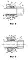
- FIG. 8 illustrates a section through the quick coupling in FIG. 7 in a first, locked position
- FIG. 9 illustrates a section through the quick coupling in FIG. 7 in a second, locked position.
- a quick coupling 1 with a pipe 2 is shown partially sectioned in FIG. 1 .
- the same quick coupling 1 is shown again in FIG. 2 , but without the pipe 2 .
- the quick coupling 1 consists of a coupling body 3 with a receiving opening 4 .
- the end 5 of the pipe 2 is inserted into the receiving opening 4 , as into a sleeve, to produce a connection with the pipe 2 .
- the coupling body 3 is illustrated in the form of a sleeve on the left-hand side in FIG. 1 .
- a connection area 6 is illustrated schematically on the right-hand side.
- the connection area 6 is used to connect the quick coupling 1 and the pipe 2 to further, medium-carrying pipes or apparatuses.
- the connection area 6 can be screwed into or welded to an opening in a container, for example.
- the connection area 6 can also be executed symmetrically as a mirror image as a further sleeve-shaped coupling body.
- the quick coupling 1 receives a retaining element 7 , a sealing element 8 and a securing element 9 one after the other, viewed from the connection area 6 , in the sleeve-shaped coupling body 3 .
- the retaining element 7 is represented here as a closed ring with a flange ring 11 and with teeth 12 facing inwards at an angle.
- the flange ring 11 lies perpendicular to the axis x of the pipe and thus parallel to a first shoulder 13 in the coupling body 3 .
- the teeth 12 face at an angle towards the end 5 of the pipe 2 .
- the retaining element 7 is made in a single piece from a material that is considerably harder and more rigid than the material of the pipe 2 .
- the retaining element 7 can be made from a metal or from a plastic material, depending on the nature of the medium that is conveyed inside the pipe.
- FIG. 1 shows how the pipe 2 , when it is subjected to a load, i.e. either by a pulling force which is applied to the pipe externally, or by a pressure which acts upon the pipe from the inside, is displaced only to a small degree.
- the internal diameter of the retaining element 7 in the unloaded state essentially coincides with the external diameter of the pipe 2 .
- the external circumference of the second shoulder 14 is also adapted to the external diameter of the pipe 2 . Effective guiding of the pipe 2 in the coupling body 3 is achieved in this way.
- the sealing element 8 is made of a considerably softer material than the retaining element 7 .
- the sealing element 8 is executed as a ring with a rectangular profile.
- a plurality of sealing ribs 15 , 16 are formed on the radially inward-facing and outward-facing walls of the sealing element 8 .
- the sealing ribs 15 , 16 face inwards and outwards, in the manner of a saw tooth.
- Adequate sealing of the coupling body 3 is achieved through the arrangement of the sealing ribs 15 , 16 and through the dimensioning and flexibility of the material.
- the sealing element 8 is capable, because it has a rectangular profile, of being connected before pre-assembly by gluing to the parallel flange ring 11 of the retaining element 7 to form a single unit.
- the securing element 9 is also pre-assembled in the coupling body 3 at the pre-assembly stage.
- the securing element 9 is executed as a ring with a U-shaped profile.
- the free ends 17 , 18 of the U engage around the receiving opening 4 of the coupling body 3 .
- the securing element 9 is made from a plastic material by an injection molding process.
- the free ends 17 , 18 of the securing element 9 are executed with an elastic and resilient form and exhibit locking projections 19 , 20 facing perpendicularly inwards in each case on the inside of the U.
- Also arranged on the external surface 21 and the internal surface 22 of the coupling body 3 are locking ribs 23 , 24 , which interact with the locking projections 19 , 20 in order to effect locking.
- the quick coupling 1 is illustrated in FIG. 3 as a perspective view in the manner of an exploded representation.
- the outward-facing locking projections 19 and the inward-facing locking projections 20 can be seen on the securing element 9 .
- the outward-facing locking projections 19 interact with the first locking rib 23 , which can be seen in FIGS. 1 and 2 at the end of the receiving opening 4 on the inside of the coupling body 3 .
- the inward-facing locking projections 20 interact with the second locking rib 24 , which can be seen in FIGS. 1 , 2 and 3 on the outside of the coupling body 3 .
- the locking ribs 23 , 24 form a radial reinforcement on the periphery of the wall of the coupling body 3 .
- the manner in which three locking projections 19 , 20 are arranged regularly around the periphery in each case at an angular separation of 120° can be seen in FIG. 3 .
- the second, outer locking rib 24 is, in comparison with the first, inner locking rib 23 , executed at a different distance from the end of the coupling body 3 .
- the securing element 9 can be attached to the coupling body 3 at two points: a first, front pre-locking position and a second, rear final locking position.
- the quick coupling 1 is pre-assembled and supplied with the securing element 9 in the pre-locking position and can be brought by the user into the rear final locking position after inserting the end 5 of the pipe. Secure assembly can be verified by a clearly audible click produced by the locking ribs 23 , 24 and the locking projections 19 , 20 .
- the sealing ribs 15 , 16 on the inner and outer wall of the sealing element 8 can also be seen in FIG. 3 .
- FIGS. 4 , 5 and 6 A second illustrative embodiment of the quick coupling 1 is represented in FIGS. 4 , 5 and 6 .
- the retaining element 7 exhibits a plurality of arms 25 attached to the radially oriented flange ring 11 , which arms are oriented in an axial direction.
- the arms 25 exhibit locking fingers 26 at each of their ends.
- the locking fingers 26 engage in matching openings 27 in the wall of the coupling body 3 .
- Secure positioning of the retaining element 7 inside the coupling body 3 in the radial and axial directions is achieved in this way.
- the retaining element 7 and the sealing element 8 have been manufactured together as a single unit.
- the retaining element 7 which is manufactured from a plastic material for example, is attached to a one-piece element by extruding the arms 25 with the elastomer sealing element 8 .
- a one-piece element is produced in this way, which performs both the retaining function and the sealing function. As a consequence of this, stocks of only a few parts require to be maintained. Pre-assembly of the quick coupling 1 is accordingly simpler and more rapid.
- the retaining element 7 which is extruded together with the sealing element 8 , is illustrated on its own in FIG. 5 .
- the quick coupling 1 is illustrated as a sectioned view in FIG. 6 without the end 5 of a pipe and without the securing element 9 .
- a third illustrative embodiment of the quick coupling 1 is shown twice as a perspective representation in FIG. 7 .
- a pipe 2 , a securing element 9 , a sealing element 8 , a retaining element 7 and a coupling body 3 are represented one after the other, as in FIG. 3 .
- the coupling body 3 is executed as a screw-in sleeve 3 with a connection area executed as a thread 31 and with an attachment area executed as a hexagonal nut 32 . In this way, the coupling body 3 can be screwed into holes in the walls of containers or into additional pipe connection elements, for example.
- Two annular locking ribs 33 , 34 are executed at the opposite end of the coupling body 3 on the outer periphery.
- the first locking rib 33 which is executed immediately adjacent to the end of the coupling body 3 , has a smaller external diameter than the second locking rib 34 , which is executed between the first locking rib 33 and the nut 32 .
- the retaining element 7 is identical with the retaining element in FIGS. 1 to 3 .
- the sealing element is executed essentially as a ring 8 made from an elastomer material with a rectangular profile.
- An annular groove 81 is executed on the face of the ring 8 facing towards the screw-in thread 31 .
- Sealing beads 82 and interjacent constrictions 83 are executed on the inside and the outside of the ring 8 .
- the groove 81 , the sealing beads 82 and the constrictions 83 serve to increase the elasticity of the sealing element 8 . This enables the sealing effect of the ring 8 to be assured, even in the case of quite large variations in the tolerance of the dimensions of the coupling body 3 and the pipe 2 .
- the securing element 9 is executed in a similar fashion to the securing element in FIGS. 1 to 3 .
- the securing element 9 consists of two rings 91 , 92 , with different diameters, which are so arranged as to lie one inside the other.
- the rings are executed as the legs of a U and are attached to one another.
- the inner ring 91 has a shorter length, viewed in the axial direction, than the outer ring 92 .
- the outer ring 92 exhibits locking projections 93 oriented radially inwards, which interact with the locking ribs 33 , 34 on the outer periphery of the coupling body 3 .
- the locking projections 93 are uniformly distributed around the periphery of the outer ring 92 .
- FIG. 7 Three locking projections 93 are represented in FIG. 7 .
- gaps 94 for parts of the injection molding tool are provided in the area between the legs of the U. It is possible by this means to achieve easier removal of the securing element 9 from the mold as an injection-molded component during manufacture.
- the quick coupling 1 in FIG. 7 is shown as a sectioned view in FIGS. 8 and 9 .
- the state of the quick coupling after delivery to the customer is illustrated in FIG. 8 .
- the securing element 9 is engaged with the locking projections 93 behind the first locking rib 33 of the coupling body 3 . In this position, the pipe 2 can be introduced into the coupling body 3 .
- the securing element 9 is engaged with the locking projections 93 of the outer ring 92 behind the second locking rib 34 of the coupling body 3 .
- the inner ring 91 of the securing element 9 exerts a pressure on the sealing element 8 acting in the axial direction.
- the pipe 2 is attached to the coupling body 3 in such a way that it is sealed against the medium.
- the retaining element 7 is pressed in between the coupling body 3 and the sealing element 8 , and the inward-inclined teeth 12 of the retaining element 7 engage in the external wall of the pipe 2 .
- the inclined position of the teeth 12 prevents the pipe 2 from being pulled out of the coupling body 3 .
- Also illustrated in FIG. 9 is the manner in which the sealing beads 82 touch the walls of the coupling body 3 and the pipe 2 , and the manner in which the sealing element 8 is caused to deform thereby.
- a simple pipe connection element is offered, which is constructed from a small number of individual components, which element is supplied in the pre-assembled state and which avoids the need for the end user to use special tools, such as crimping pliers.
- the pipe can be inserted into the quick coupling without special processing or preparation of the end of the pipe. This means that, even in the event of a subsequent repair, the connection can be separated easily, and the pipe can then be re-inserted into a new quick connector.
- the quick connector 1 can be constructed entirely from plastic components and is suitable in particular for fairly small pipe diameters.
- the quick coupling 1 can be used both for pipes carrying a medium and for the secure and sealing passage of cables or rods through walls.
Landscapes
- Engineering & Computer Science (AREA)
- General Engineering & Computer Science (AREA)
- Mechanical Engineering (AREA)
- Quick-Acting Or Multi-Walled Pipe Joints (AREA)
- Containers And Packaging Bodies Having A Special Means To Remove Contents (AREA)
- Compositions Of Oxide Ceramics (AREA)
- Media Introduction/Drainage Providing Device (AREA)
Applications Claiming Priority (2)
| Application Number | Priority Date | Filing Date | Title |
|---|---|---|---|
| EP04026416A EP1655529B1 (de) | 2004-11-08 | 2004-11-08 | Schnellkupplung |
| EP04026416.0 | 2004-11-08 |
Publications (2)
| Publication Number | Publication Date |
|---|---|
| US20060108802A1 US20060108802A1 (en) | 2006-05-25 |
| US7434846B2 true US7434846B2 (en) | 2008-10-14 |
Family
ID=34927273
Family Applications (1)
| Application Number | Title | Priority Date | Filing Date |
|---|---|---|---|
| US11/117,887 Expired - Fee Related US7434846B2 (en) | 2004-11-08 | 2005-04-28 | Quick coupling |
Country Status (4)
| Country | Link |
|---|---|
| US (1) | US7434846B2 (de) |
| EP (1) | EP1655529B1 (de) |
| AT (1) | ATE412846T1 (de) |
| DE (1) | DE502004008357D1 (de) |
Cited By (38)
| Publication number | Priority date | Publication date | Assignee | Title |
|---|---|---|---|---|
| US20070108764A1 (en) * | 2005-11-04 | 2007-05-17 | Aldo Nicolino | Fast-fit coupling for a fluid circulation system |
| US20080084064A1 (en) * | 2006-10-06 | 2008-04-10 | Ti Group Automotive Systems, Llc | Quick connector coupling |
| US20110089681A1 (en) * | 2009-10-21 | 2011-04-21 | Schutte Joseph P | Supply stop with connection verification |
| US20110089684A1 (en) * | 2009-10-21 | 2011-04-21 | Schutte Joseph P | Anti-rotation gripper ring |
| US20110088790A1 (en) * | 2009-10-21 | 2011-04-21 | Schutte Joseph P | Bias release cartridge |
| US20110214886A1 (en) * | 2010-03-05 | 2011-09-08 | The Viking Corporation | Push On Threadless Sprinkler And Fitting |
| USD645547S1 (en) | 2007-11-19 | 2011-09-20 | Value Plastics, Inc. | Male quick connect fitting |
| USD649240S1 (en) | 2009-12-09 | 2011-11-22 | Value Plastics, Inc. | Male dual lumen bayonet connector |
| USD650478S1 (en) | 2009-12-23 | 2011-12-13 | Value Plastics, Inc. | Female dual lumen connector |
| USD652510S1 (en) | 2011-02-11 | 2012-01-17 | Value Plastics, Inc. | Connector for fluid tubing |
| USD652511S1 (en) | 2011-02-11 | 2012-01-17 | Value Plastics, Inc. | Female body of connector for fluid tubing |
| US8113546B2 (en) | 2005-06-10 | 2012-02-14 | Value Plastics, Inc. | Latching female fluid tubing coupler |
| USD655393S1 (en) | 2009-06-23 | 2012-03-06 | Value Plastics, Inc. | Multi-port valve |
| USD663022S1 (en) | 2011-02-11 | 2012-07-03 | Nordson Corporation | Male body of connector for fluid tubing |
| US8235426B2 (en) | 2008-07-03 | 2012-08-07 | Nordson Corporation | Latch assembly for joining two conduits |
| US8397756B2 (en) | 2006-01-20 | 2013-03-19 | Nordson Corporation | Fluid conduit couplers with depressible latch mechanism |
| USD698440S1 (en) | 2011-07-29 | 2014-01-28 | Nordson Corporation | Connector for fluid tubing |
| USD699841S1 (en) | 2011-07-29 | 2014-02-18 | Nordson Corporation | Female body of connector for fluid tubing |
| USD699840S1 (en) | 2011-07-29 | 2014-02-18 | Nordson Corporation | Male body of connector for fluid tubing |
| USD709612S1 (en) | 2011-12-23 | 2014-07-22 | Nordson Corporation | Female dual lumen connector |
| US9046205B2 (en) | 2009-12-09 | 2015-06-02 | Nordson Corporation | Fluid connector latches with profile lead-ins |
| US9115837B2 (en) | 2012-11-05 | 2015-08-25 | TI Automotive (Fuldabrück) GmbH | Quick connector coupling |
| US9388929B2 (en) | 2009-12-09 | 2016-07-12 | Nordson Corporation | Male bayonet connector |
| US20160273695A1 (en) * | 2013-12-11 | 2016-09-22 | Nibco Inc. | Modular push-to-connect assembly |
| US9464741B2 (en) | 2009-12-09 | 2016-10-11 | Nordson Corporation | Button latch with integrally molded cantilever springs |
| US9506592B2 (en) | 2009-10-21 | 2016-11-29 | Brass-Craft Manufacturing Company | Supply stop with connection verification |
| USD785790S1 (en) | 2009-12-09 | 2017-05-02 | General Electric Company | Male dual lumen bayonet connector |
| US9707386B2 (en) | 2009-02-07 | 2017-07-18 | Merit Medical Systems, Inc. | Valved connector |
| US20170328505A1 (en) * | 2016-05-16 | 2017-11-16 | Victaulic Company | Coupling Having Tabbed Retainer |
| US9890887B2 (en) | 2013-01-15 | 2018-02-13 | TI Automotive (Fuldabrück) GmbH | Quick connector |
| USD838366S1 (en) | 2016-10-31 | 2019-01-15 | Nordson Corporation | Blood pressure connector |
| US10578234B2 (en) | 2013-05-02 | 2020-03-03 | Victaulic Company | Coupling having arcuate stiffness ribs |
| US10605394B2 (en) | 2016-05-16 | 2020-03-31 | Victaulic Company | Fitting having tabbed retainer and observation apertures |
| US10711930B2 (en) | 2009-12-09 | 2020-07-14 | Nordson Corporation | Releasable connection assembly |
| US10731780B2 (en) | 2016-05-16 | 2020-08-04 | Victaulic Company | Sprung coupling |
| US11060639B2 (en) | 2015-12-28 | 2021-07-13 | Victaulic Company | Adapter coupling |
| US11560967B2 (en) | 2018-09-04 | 2023-01-24 | Brasscraft Manufacturing Company | Rotation-resistant push-on conduit coupling cartridge |
| US11781683B2 (en) | 2019-11-15 | 2023-10-10 | Victaulic Company | Shrouded coupling |
Families Citing this family (18)
| Publication number | Priority date | Publication date | Assignee | Title |
|---|---|---|---|---|
| US7021672B2 (en) * | 2003-05-29 | 2006-04-04 | Orbit Irrigation Products, Inc. | Irrigation coupling apparatus and method |
| US9604404B2 (en) | 2003-05-29 | 2017-03-28 | Orbit Irrigation Products, Inc. | Conduit coupling apparatus and method |
| US20090160179A1 (en) * | 2003-05-29 | 2009-06-25 | Ericksen Kent C | Coupling release mechanism for irrigation system |
| US9429262B2 (en) | 2003-05-29 | 2016-08-30 | Orbit Irrigation Products, Inc. | Conduit coupling apparatus and method |
| US20090160178A1 (en) * | 2003-05-29 | 2009-06-25 | Ericksen Kent C | Centering system for coupling for irrigation system |
| US20070223994A1 (en) * | 2004-09-13 | 2007-09-27 | Murray Cohen | Integrated locking device |
| DE102006015158B4 (de) * | 2006-03-30 | 2009-10-29 | Kaimer Gmbh & Co. Holding Kg | Steckverbinder |
| CN101112272B (zh) * | 2006-07-28 | 2010-09-08 | 海尔集团公司 | 具有多用途顶板的酒柜 |
| US7644955B1 (en) * | 2008-07-03 | 2010-01-12 | Naris Komolrochanaporn | Quick coupling type fitting |
| FR2934029B1 (fr) * | 2008-07-16 | 2010-08-13 | Contitech Anoflex Sas | Raccord enfichable pour tuyau |
| KR101733241B1 (ko) * | 2010-03-15 | 2017-05-08 | 엘지전자 주식회사 | 냉장고 |
| US11384872B1 (en) | 2011-05-24 | 2022-07-12 | Husqvarna Ab | Conduit coupling apparatus and method |
| US8657343B2 (en) * | 2012-02-06 | 2014-02-25 | Watts Water Technologies, Inc. | Quick connector assembly |
| USD732359S1 (en) | 2012-08-21 | 2015-06-23 | Orbit Irrigation Products, Inc. | Conduit removal tool |
| DE102012021683A1 (de) * | 2012-11-03 | 2014-05-08 | Festo Ag & Co. Kg | Anschlussvorrichtung für mindestens eine Fluiddleitung |
| DE102014225280A1 (de) * | 2014-12-09 | 2016-06-09 | Festo Ag & Co. Kg | Anschlussvorrichtung für eine Fluidleitung |
| US20190219207A1 (en) * | 2018-01-16 | 2019-07-18 | Rain Bird Corporation | Push To Connect Coupling |
| DE202022104511U1 (de) * | 2022-08-08 | 2023-11-09 | Neoperl Gmbh | Schlauchaufnahme |
Citations (15)
| Publication number | Priority date | Publication date | Assignee | Title |
|---|---|---|---|---|
| US2999701A (en) * | 1959-04-08 | 1961-09-12 | Chicago Forging & Mfg Co | Pipe coupling having sealing and anchoring means |
| US3177018A (en) * | 1963-01-02 | 1965-04-06 | Aeroquip Corp | Snap ring coupling |
| US3874709A (en) * | 1972-09-18 | 1975-04-01 | Cardinal Of Adrian | Tubing fitting |
| US4146254A (en) * | 1976-03-31 | 1979-03-27 | Bristol Products, Inc. | Coupler for tubing |
| US4630848A (en) | 1984-06-13 | 1986-12-23 | Hawke Cable Glands Limited | Releasable coupling for tubes or pipes |
| US4635975A (en) | 1985-09-25 | 1987-01-13 | Jaco Manufacturing Company | Quick-connect tube coupling |
| WO1990008288A1 (en) | 1989-01-11 | 1990-07-26 | Royack 1 Limited | Pipe coupling |
| EP0696342A1 (de) | 1993-04-29 | 1996-02-14 | Wavin Bv | Schnellkupplung für rohre oder schläuche |
| US5603530A (en) | 1994-09-14 | 1997-02-18 | Guest; John D. | Grab rings |
| US5722696A (en) * | 1995-04-13 | 1998-03-03 | Smc Kabushiki Kaisha | Easy-connect-and-disconnect tube coupling |
| GB2334562A (en) | 1998-02-20 | 1999-08-25 | Eden Limited | A connector |
| US6089620A (en) * | 1996-07-19 | 2000-07-18 | Fico Transpar, S.A. | Rapid connection and disconnection device for electropumps and conduits for motor vehicle wind-shield washing systems |
| EP1215434A1 (de) | 2000-12-18 | 2002-06-19 | José Maria Ferrer Beltran | Sichere Verbindung für Flüssigkeitssysteme |
| US20030127855A1 (en) * | 2002-01-10 | 2003-07-10 | Holm Industries, Inc. | Integrated quick connect corrugated tubing assembly |
| USRE38204E1 (en) * | 1996-07-12 | 2003-07-29 | Container Technology, Inc. | Fluid coupling for matching delivery and supply lines irrespective of the relative rotational positions of the coupling members |
-
2004
- 2004-11-08 AT AT04026416T patent/ATE412846T1/de active
- 2004-11-08 EP EP04026416A patent/EP1655529B1/de not_active Not-in-force
- 2004-11-08 DE DE502004008357T patent/DE502004008357D1/de active Active
-
2005
- 2005-04-28 US US11/117,887 patent/US7434846B2/en not_active Expired - Fee Related
Patent Citations (15)
| Publication number | Priority date | Publication date | Assignee | Title |
|---|---|---|---|---|
| US2999701A (en) * | 1959-04-08 | 1961-09-12 | Chicago Forging & Mfg Co | Pipe coupling having sealing and anchoring means |
| US3177018A (en) * | 1963-01-02 | 1965-04-06 | Aeroquip Corp | Snap ring coupling |
| US3874709A (en) * | 1972-09-18 | 1975-04-01 | Cardinal Of Adrian | Tubing fitting |
| US4146254A (en) * | 1976-03-31 | 1979-03-27 | Bristol Products, Inc. | Coupler for tubing |
| US4630848A (en) | 1984-06-13 | 1986-12-23 | Hawke Cable Glands Limited | Releasable coupling for tubes or pipes |
| US4635975A (en) | 1985-09-25 | 1987-01-13 | Jaco Manufacturing Company | Quick-connect tube coupling |
| WO1990008288A1 (en) | 1989-01-11 | 1990-07-26 | Royack 1 Limited | Pipe coupling |
| EP0696342A1 (de) | 1993-04-29 | 1996-02-14 | Wavin Bv | Schnellkupplung für rohre oder schläuche |
| US5603530A (en) | 1994-09-14 | 1997-02-18 | Guest; John D. | Grab rings |
| US5722696A (en) * | 1995-04-13 | 1998-03-03 | Smc Kabushiki Kaisha | Easy-connect-and-disconnect tube coupling |
| USRE38204E1 (en) * | 1996-07-12 | 2003-07-29 | Container Technology, Inc. | Fluid coupling for matching delivery and supply lines irrespective of the relative rotational positions of the coupling members |
| US6089620A (en) * | 1996-07-19 | 2000-07-18 | Fico Transpar, S.A. | Rapid connection and disconnection device for electropumps and conduits for motor vehicle wind-shield washing systems |
| GB2334562A (en) | 1998-02-20 | 1999-08-25 | Eden Limited | A connector |
| EP1215434A1 (de) | 2000-12-18 | 2002-06-19 | José Maria Ferrer Beltran | Sichere Verbindung für Flüssigkeitssysteme |
| US20030127855A1 (en) * | 2002-01-10 | 2003-07-10 | Holm Industries, Inc. | Integrated quick connect corrugated tubing assembly |
Cited By (60)
| Publication number | Priority date | Publication date | Assignee | Title |
|---|---|---|---|---|
| US8113546B2 (en) | 2005-06-10 | 2012-02-14 | Value Plastics, Inc. | Latching female fluid tubing coupler |
| US20070108764A1 (en) * | 2005-11-04 | 2007-05-17 | Aldo Nicolino | Fast-fit coupling for a fluid circulation system |
| US7600788B2 (en) * | 2005-11-04 | 2009-10-13 | Pres-Block, S.P.A. | Fast-fit coupling for a fluid circulation system |
| US8397756B2 (en) | 2006-01-20 | 2013-03-19 | Nordson Corporation | Fluid conduit couplers with depressible latch mechanism |
| US7731245B2 (en) * | 2006-10-06 | 2010-06-08 | Ti Group Automotive Systems, Llc | Quick connector coupling |
| US20080084064A1 (en) * | 2006-10-06 | 2008-04-10 | Ti Group Automotive Systems, Llc | Quick connector coupling |
| USD645547S1 (en) | 2007-11-19 | 2011-09-20 | Value Plastics, Inc. | Male quick connect fitting |
| USD654573S1 (en) | 2007-11-19 | 2012-02-21 | Value Plastics, Inc. | Female quick connect fitting |
| US8596688B2 (en) | 2008-07-03 | 2013-12-03 | Nordson Corporation | Latch assembly for joining two conduits |
| US8448994B2 (en) | 2008-07-03 | 2013-05-28 | Nordson Corporation | Latch assembly for joining two conduits |
| US8235426B2 (en) | 2008-07-03 | 2012-08-07 | Nordson Corporation | Latch assembly for joining two conduits |
| US9707386B2 (en) | 2009-02-07 | 2017-07-18 | Merit Medical Systems, Inc. | Valved connector |
| USD655393S1 (en) | 2009-06-23 | 2012-03-06 | Value Plastics, Inc. | Multi-port valve |
| US20110089684A1 (en) * | 2009-10-21 | 2011-04-21 | Schutte Joseph P | Anti-rotation gripper ring |
| US9464743B2 (en) | 2009-10-21 | 2016-10-11 | Brass-Craft Manufacturing Company | Bias release cartridge |
| US9494268B2 (en) | 2009-10-21 | 2016-11-15 | Brasscraft Manufacturing Company | Supply stop with connection verification |
| US9506592B2 (en) | 2009-10-21 | 2016-11-29 | Brass-Craft Manufacturing Company | Supply stop with connection verification |
| US9523454B2 (en) | 2009-10-21 | 2016-12-20 | Brasscraft Manufacturing Company | Anti-rotation gripper ring |
| US20110088790A1 (en) * | 2009-10-21 | 2011-04-21 | Schutte Joseph P | Bias release cartridge |
| US20110089681A1 (en) * | 2009-10-21 | 2011-04-21 | Schutte Joseph P | Supply stop with connection verification |
| US9464741B2 (en) | 2009-12-09 | 2016-10-11 | Nordson Corporation | Button latch with integrally molded cantilever springs |
| US9388929B2 (en) | 2009-12-09 | 2016-07-12 | Nordson Corporation | Male bayonet connector |
| US10001236B2 (en) | 2009-12-09 | 2018-06-19 | General Electric Company | Male bayonet connector |
| US9732891B2 (en) | 2009-12-09 | 2017-08-15 | General Electric Company | Male bayonet connector |
| USD785790S1 (en) | 2009-12-09 | 2017-05-02 | General Electric Company | Male dual lumen bayonet connector |
| USD649240S1 (en) | 2009-12-09 | 2011-11-22 | Value Plastics, Inc. | Male dual lumen bayonet connector |
| US9046205B2 (en) | 2009-12-09 | 2015-06-02 | Nordson Corporation | Fluid connector latches with profile lead-ins |
| US10711930B2 (en) | 2009-12-09 | 2020-07-14 | Nordson Corporation | Releasable connection assembly |
| USD650478S1 (en) | 2009-12-23 | 2011-12-13 | Value Plastics, Inc. | Female dual lumen connector |
| US20110214886A1 (en) * | 2010-03-05 | 2011-09-08 | The Viking Corporation | Push On Threadless Sprinkler And Fitting |
| USD663022S1 (en) | 2011-02-11 | 2012-07-03 | Nordson Corporation | Male body of connector for fluid tubing |
| USD652511S1 (en) | 2011-02-11 | 2012-01-17 | Value Plastics, Inc. | Female body of connector for fluid tubing |
| USD652510S1 (en) | 2011-02-11 | 2012-01-17 | Value Plastics, Inc. | Connector for fluid tubing |
| USD698440S1 (en) | 2011-07-29 | 2014-01-28 | Nordson Corporation | Connector for fluid tubing |
| USD712537S1 (en) | 2011-07-29 | 2014-09-02 | Nordson Corporation | Connector for fluid tubing |
| USD699840S1 (en) | 2011-07-29 | 2014-02-18 | Nordson Corporation | Male body of connector for fluid tubing |
| USD699841S1 (en) | 2011-07-29 | 2014-02-18 | Nordson Corporation | Female body of connector for fluid tubing |
| USD709612S1 (en) | 2011-12-23 | 2014-07-22 | Nordson Corporation | Female dual lumen connector |
| US9115837B2 (en) | 2012-11-05 | 2015-08-25 | TI Automotive (Fuldabrück) GmbH | Quick connector coupling |
| US9890887B2 (en) | 2013-01-15 | 2018-02-13 | TI Automotive (Fuldabrück) GmbH | Quick connector |
| US10578234B2 (en) | 2013-05-02 | 2020-03-03 | Victaulic Company | Coupling having arcuate stiffness ribs |
| US20160273695A1 (en) * | 2013-12-11 | 2016-09-22 | Nibco Inc. | Modular push-to-connect assembly |
| US10006575B2 (en) * | 2013-12-11 | 2018-06-26 | Nibco Inc. | Modular push-to-connect assembly |
| US11725756B2 (en) | 2015-12-28 | 2023-08-15 | Victaulic Company | Adapter coupling |
| US11060639B2 (en) | 2015-12-28 | 2021-07-13 | Victaulic Company | Adapter coupling |
| US10605394B2 (en) | 2016-05-16 | 2020-03-31 | Victaulic Company | Fitting having tabbed retainer and observation apertures |
| US11821546B2 (en) | 2016-05-16 | 2023-11-21 | Victaulic Company | Sprung coupling |
| US10731780B2 (en) | 2016-05-16 | 2020-08-04 | Victaulic Company | Sprung coupling |
| US10533688B2 (en) * | 2016-05-16 | 2020-01-14 | Victaulic Company | Coupling having tabbed retainer |
| US11125369B2 (en) | 2016-05-16 | 2021-09-21 | Victaulic Company | Coupling having tabbed retainer |
| US11879571B2 (en) | 2016-05-16 | 2024-01-23 | Victaulic Company | Captured element coupling |
| US11859737B2 (en) | 2016-05-16 | 2024-01-02 | Victaulic Company | Captured element coupling |
| US20170328505A1 (en) * | 2016-05-16 | 2017-11-16 | Victaulic Company | Coupling Having Tabbed Retainer |
| USD964558S1 (en) | 2016-10-31 | 2022-09-20 | Nordson Corporation | Blood pressure connector |
| USD838366S1 (en) | 2016-10-31 | 2019-01-15 | Nordson Corporation | Blood pressure connector |
| USD967955S1 (en) | 2016-10-31 | 2022-10-25 | Nordson Corporation | Blood pressure connector |
| USD964557S1 (en) | 2016-10-31 | 2022-09-20 | Nordson Corporation | Blood pressure connector |
| USD961070S1 (en) | 2016-10-31 | 2022-08-16 | Nordson Corporation | Blood pressure connector |
| US11560967B2 (en) | 2018-09-04 | 2023-01-24 | Brasscraft Manufacturing Company | Rotation-resistant push-on conduit coupling cartridge |
| US11781683B2 (en) | 2019-11-15 | 2023-10-10 | Victaulic Company | Shrouded coupling |
Also Published As
| Publication number | Publication date |
|---|---|
| EP1655529A1 (de) | 2006-05-10 |
| DE502004008357D1 (de) | 2008-12-11 |
| EP1655529B1 (de) | 2008-10-29 |
| US20060108802A1 (en) | 2006-05-25 |
| ATE412846T1 (de) | 2008-11-15 |
Similar Documents
| Publication | Publication Date | Title |
|---|---|---|
| US7434846B2 (en) | Quick coupling | |
| US7455330B2 (en) | Quick coupling | |
| US6231090B1 (en) | Tubular joint | |
| US8056937B2 (en) | Tube couplings | |
| US10563802B2 (en) | Device for hose fitting | |
| US7677610B2 (en) | Connection and joint piece for well tubes | |
| US7819437B2 (en) | Flexible captive flange hose connection and method | |
| US20140116552A1 (en) | Hose nipple and corresponding hose arrangement | |
| EP2213927B1 (de) | Schlauchfassung und Verfahren zum Befestigen für die Schlauchfassung an einem Schlauch | |
| US10415728B2 (en) | Seal for a pipe coupling | |
| US5472244A (en) | Plastic coupling for plastic tubing | |
| WO2002055918A1 (fr) | Pate d'etancheite pour joint | |
| US7014221B2 (en) | Joint for piping | |
| US20040178630A1 (en) | Pipe coupling | |
| US20040135369A1 (en) | Corrugated pipe connecting arrangement and corrugated pipe | |
| US20110133447A1 (en) | Plug-in hose coupling | |
| JP2002529662A (ja) | 波形管用の結合および接続部品 | |
| KR20220070317A (ko) | 플라스틱으로 제조된 신속 연결부 | |
| JP5108290B2 (ja) | 口金具、及びホースの口金具加締め方法 | |
| JP3470158B2 (ja) | 継手部をもつホース | |
| JP4102587B2 (ja) | 金属管とゴムホースとの継手具 | |
| CN215111246U (zh) | 一体式管接头及管道连接结构 | |
| JPH09257171A (ja) | チューブの接続構造 | |
| US6179341B1 (en) | Quick connect retainer having tolerance for wide band of male tube dimensions | |
| JP3665847B2 (ja) | 合成樹脂管の接続端部を気密または液密にシールする構造 |
Legal Events
| Date | Code | Title | Description |
|---|---|---|---|
| AS | Assignment |
Owner name: KULM HOLDING AG, SWITZERLAND Free format text: ASSIGNMENT OF ASSIGNORS INTEREST;ASSIGNOR:BAUMGARTNER, HANS;REEL/FRAME:016783/0098 Effective date: 20050511 |
|
| FPAY | Fee payment |
Year of fee payment: 4 |
|
| AS | Assignment |
Owner name: SERTO HOLDING AG, SWITZERLAND Free format text: ASSIGNMENT OF ASSIGNORS INTEREST;ASSIGNOR:KULM HOLDING AG;REEL/FRAME:028011/0440 Effective date: 20120331 |
|
| REMI | Maintenance fee reminder mailed | ||
| LAPS | Lapse for failure to pay maintenance fees | ||
| STCH | Information on status: patent discontinuation |
Free format text: PATENT EXPIRED DUE TO NONPAYMENT OF MAINTENANCE FEES UNDER 37 CFR 1.362 |
|
| FP | Lapsed due to failure to pay maintenance fee |
Effective date: 20161014 |