US7434683B1 - Protective case including rigid shell members - Google Patents
Protective case including rigid shell members Download PDFInfo
- Publication number
- US7434683B1 US7434683B1 US11/259,517 US25951705A US7434683B1 US 7434683 B1 US7434683 B1 US 7434683B1 US 25951705 A US25951705 A US 25951705A US 7434683 B1 US7434683 B1 US 7434683B1
- Authority
- US
- United States
- Prior art keywords
- case
- wall boundary
- rigid
- portions
- side wall
- Prior art date
- Legal status (The legal status is an assumption and is not a legal conclusion. Google has not performed a legal analysis and makes no representation as to the accuracy of the status listed.)
- Expired - Fee Related, expires
Links
Images


Classifications
-
- A—HUMAN NECESSITIES
- A45—HAND OR TRAVELLING ARTICLES
- A45C—PURSES; LUGGAGE; HAND CARRIED BAGS
- A45C5/00—Rigid or semi-rigid luggage
-
- F—MECHANICAL ENGINEERING; LIGHTING; HEATING; WEAPONS; BLASTING
- F41—WEAPONS
- F41C—SMALLARMS, e.g. PISTOLS, RIFLES; ACCESSORIES THEREFOR
- F41C33/00—Means for wearing or carrying smallarms
- F41C33/06—Containers for carrying smallarms, e.g. safety boxes, gun cases
-
- A—HUMAN NECESSITIES
- A45—HAND OR TRAVELLING ARTICLES
- A45C—PURSES; LUGGAGE; HAND CARRIED BAGS
- A45C5/00—Rigid or semi-rigid luggage
- A45C5/03—Suitcases
- A45C2005/032—Suitcases semi-rigid, i.e. resistant against deformation and resilient, e.g. with a resilient frame
-
- A—HUMAN NECESSITIES
- A45—HAND OR TRAVELLING ARTICLES
- A45C—PURSES; LUGGAGE; HAND CARRIED BAGS
- A45C5/00—Rigid or semi-rigid luggage
- A45C5/03—Suitcases
- A45C2005/037—Suitcases with a hard shell, i.e. rigid shell as volume creating element
Definitions
- the present invention relates to carrying, storage and transportation cases, and more particularly, to a protective case having rigid and flexible properties.
- Conventional weapon and firearm carrying cases for carrying guns, rifles, archery bows, or the like, are utilized to carry, transport or ship such items, and are generally constructed in two different forms.
- One form has a rigid housing, the other form has a soft-walled, deformable shell formed generally around an outline of the firearm.
- Each type of case is used for a specific purpose.
- a rigid case is ideal for shipping and long-term storage, while the deformable case is ideal for portable in-field transportation.
- a user is required to own both types of cases and chooses one over the other for certain activities when neither may be individually suited for the activity separately.
- Rigid cases are generally formed from a metallic or plastic material having a base and lid connected by an elongated piano-type hinge.
- the interior is usually filled with a padding material conforming to the interior dimensions to provide cushioning and for securing the contents against movement within the case.
- This style of case provides increased protection at the expense of size and portability.
- a rigid case is heavy and non-deformable. As a result, these cases have limited utility, and are best suited for shipping by commercial carrier or for use in long-term storage. Such rigid cases are cumbersome to carry in the field, such as when a hunter must backpack or use an all-terrain vehicle.
- piano-type hinges are subject to damage when improperly handled during the loading, storage or unloading of the case. The protective capability of a rigid case is compromised when the hinge is damaged.
- a soft sided case is commonly formed of a layered composite, for example, a fabric, canvas, leather or leather-like exterior material and a foam or woolen-type of interior. These types of cases are light weight and flexible. Soft sided cases may be easily carried by a hunter in the field. The disadvantage of such soft sided cases is that they do not provide adequate security and protection for the contents during private or commercial shipping. Further, the soft sided cases are not suitable for mounting using brackets to an all-terrain vehicle.
- a protective case includes first and second shell members which form a receiving space for the case.
- the receiving space includes a top wall boundary, a bottom wall boundary and first and second side wall boundaries.
- Each of the shell members includes a centrally disposed rigid portion having a top, a bottom, and oppositely disposed first and second sides.
- the top of the rigid portion of the shell members forms a portion of the top wall boundary of the receiving space.
- the bottom of the rigid portion of the shell members forms a portion of the bottom boundary of the receiving space.
- Each of the shell members further includes a first flexible portion extending from the first side of the rigid portion and forming a portion of the top wall boundary and the bottom wall boundary of the receiving space.
- the first flexible portion extends adjacent the first side wall boundary of the receiving space.
- Each of the shell members further includes a second flexible portion extending from the second side of the rigid portion and forming a portion of the top wall boundary and the bottom wall boundary of the receiving space.
- the second flexible portion extends adjacent to the second side wall
- FIG. 1 is a perspective view of one embodiment in the form of a rifle case illustrating the present invention
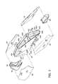
- FIG. 2 is an exploded perspective view of the case illustrated in FIG. 1 ;
- FIG. 3 is a cross-sectional view taken generally along section lines 3 - 3 of FIG. 2 ;
- FIG. 4 is a cross-sectional view taken generally along section lines 4 - 4 of FIG. 2 ;
- FIG. 5 is a perspective view of an insert for adjusting the size of the case illustrated in FIG. 1 ;
- FIG. 6 is a perspective view of an insert for adjusting the size of the case shown in FIG. 1 ;
- FIG. 7 is a top plan view of the case shown in FIG. 1 in a folded position
- FIG. 8 is a perspective view of an additional embodiment of the present invention in the form of a take-down weapon case
- FIG. 9 is a perspective view of an additional embodiment of the present invention in the form of an archery bow case.
- FIG. 10 is a perspective view of an additional embodiment of the present invention in the form of a handgun-equipment case.
- Case 20 is utilized for carrying, storage and transportation of, for example, a rifle, it being understood that the present invention can be utilized for storage, transportation and carrying of a variety of items such as, for example, weapons, binoculars, cameras, and other types of equipment. Additional embodiments of the present case are illustrated in FIGS. 8 , 9 and 10 .
- Protective case 20 includes a first shell member, generally identified by the numeral 22 , and a second shell member, generally identified by the numeral 24 .
- Shell members 22 and 24 define a receiving space, generally identified by the numeral 26 for housing the contents of case 20 .
- Case 20 is defined by a top wall boundary 28 , a bottom wall boundary 30 , a first side wall boundary 32 and a second side wall boundary 34 .
- Each shell member 22 and 24 includes a rigid portion.
- First shell member 22 includes a rigid portion, generally identified by the numeral 40 .
- Second shell member 24 includes a rigid portion, generally identified by the numeral 42 .
- First shell member 22 includes flexible portions 44 and 46 .
- Second shell member 24 includes flexible portions 48 and 50 .
- Rigid portions 40 and 42 may comprise, for example, high impact polypropylene plastic material.
- Flexible portions 44 , 46 , 48 and 50 may comprise, for example, fabric material.
- Rigid portions 40 and 42 are positioned along shell members 22 and 24 of case 20 to protect, for example, a weapon's scope/breech, muzzle, or stock area, and in the case of an archery bow, to protect the sites, strings or cam areas.
- a rigid portion 58 positioned adjacent to first side wall boundary 32 and a rigid portion 60 positioned adjacent to second side wall boundary 34 .
- Case 20 is also provided with a pocket 62 .
- Pocket 62 may also be positioned interiorly within receiving space 26 of case 20 .
- Receiving space 26 is also covered with protective padding 64 .
- a handle 66 extends from rigid portions 40 and 42 .
- Rigid portion 40 of first shell member 22 includes a top 40 a , bottom 40 b , first side 40 c and second side 40 d .
- Rigid portion 42 of second shell member 24 includes a top 42 a , bottom 42 b , first side 42 c and a second side 42 d.
- Flexible portion 44 extends between first side 40 c of rigid portion 40 and rigid portion 58 . Flexible portion 44 is attached in an area 70 located adjacent to side 40 c and overlaps rigid portion 40 in area 70 to increase the overall strength between the connection of flexible portion 44 and rigid portion 40 .
- flexible portion 48 extends between rigid portion 42 and rigid portion 58 . Flexible portion 48 overlaps a portion of rigid portion 42 (not shown).
- Flexible portion 46 extends between rigid portion 40 and rigid portion 60 . Flexible portion 46 overlaps a portion of rigid portion 42 in area 72 adjacent second side 40 d of rigid portion 40 .
- flexible portion 50 extends between rigid portion 42 and rigid portion 60 of case 20 . A portion of flexible portion 50 overlaps an area 74 of rigid portion 42 .
- Flexible members 44 , 46 , 48 and 50 are attachable to rigid portions 40 , 42 , 58 and 60 by using various attachment methods, such as, for example, sewing, gluing, riveting, heat staking, or stapling.
- Hinge 80 may comprise, for example, a piano-type hinge. Hinge 80 is covered by a protective covering 82 which may comprise, for example, an ethylene vinyl acetate material. Cover 82 prevents dirt and debris from interfering with the operation of hinge 80 .
- Shell members 22 and 24 are joined at the top wall boundary 28 of protective case 20 utilizing a zipper 84 ( FIG. 1 ).
- rigid portions 40 and 42 provide a locking feature along top 40 a and top 42 a in the form of a tongue and groove connection.
- top 42 a of rigid portion 42 includes a groove 86 for receiving a tongue portion 88 of top 40 a of rigid portion 40 to form a positive mechanical connection and provide extra rigidity to case 20 .
- Rigid portions 40 and 42 include diagonal strips 100 and 102 which increase the rigidity of rigid portions 40 and 42 .
- Strips 100 and 102 are integrally formed.
- Diagonal strip 100 includes recesses 104 which provide additional surfaces and additional strength for rigid portions 40 and 42 .
- inserts 110 FIG. 5
- 112 FIG. 6
- case 20 can be folded as illustrated in FIG. 7 to a compact configuration when not in use.
- FIGS. 8 , 9 and 10 Additional embodiments of case 20 for use with different contents are illustrated in FIGS. 8 , 9 and 10 .
- FIG. 8 illustrates a take down weapon case 114
- FIG. 9 illustrates an archery bow case 116
- FIG. 10 illustrates a handgun, camera, equipment case 118 .
- Cases 114 , 116 and 118 each include a combination of rigid and flexible portions as described with respect to case 20 .
Landscapes
- Engineering & Computer Science (AREA)
- General Engineering & Computer Science (AREA)
- Purses, Travelling Bags, Baskets, Or Suitcases (AREA)
Abstract
Description
Claims (15)
Priority Applications (1)
| Application Number | Priority Date | Filing Date | Title |
|---|---|---|---|
| US11/259,517 US7434683B1 (en) | 2005-10-26 | 2005-10-26 | Protective case including rigid shell members |
Applications Claiming Priority (1)
| Application Number | Priority Date | Filing Date | Title |
|---|---|---|---|
| US11/259,517 US7434683B1 (en) | 2005-10-26 | 2005-10-26 | Protective case including rigid shell members |
Publications (1)
| Publication Number | Publication Date |
|---|---|
| US7434683B1 true US7434683B1 (en) | 2008-10-14 |
Family
ID=39828208
Family Applications (1)
| Application Number | Title | Priority Date | Filing Date |
|---|---|---|---|
| US11/259,517 Expired - Fee Related US7434683B1 (en) | 2005-10-26 | 2005-10-26 | Protective case including rigid shell members |
Country Status (1)
| Country | Link |
|---|---|
| US (1) | US7434683B1 (en) |
Cited By (22)
| Publication number | Priority date | Publication date | Assignee | Title |
|---|---|---|---|---|
| US20110023347A1 (en) * | 2008-06-25 | 2011-02-03 | Toby Boggan | Insulated Gun Protection Article |
| US20110041376A1 (en) * | 2009-08-18 | 2011-02-24 | Nemo Equipment, Inc. | Weapon protection device |
| US20120261287A1 (en) * | 2011-04-15 | 2012-10-18 | Aerial Machine & Tool Corp. | Tactical Equipment Carrier |
| USD722430S1 (en) * | 2014-08-18 | 2015-02-17 | Nike, Inc. | Backpack |
| USD726405S1 (en) * | 2014-08-18 | 2015-04-14 | Nike, Inc. | Multi-state configurable bag |
| USD731789S1 (en) | 2013-08-12 | 2015-06-16 | The Allen Company, Inc. | Compact tactical case |
| USD744234S1 (en) | 2014-11-04 | 2015-12-01 | The Allen Company, Inc. | Gun case |
| USD759375S1 (en) * | 2014-11-14 | 2016-06-21 | The Allen Company, Inc. | Wedge gun case |
| USD782192S1 (en) * | 2015-10-09 | 2017-03-28 | The Allen Company, Inc. | Wedge gun case |
| USD784014S1 (en) | 2015-11-23 | 2017-04-18 | The Allen Company, Inc. | Handgun case |
| USD796194S1 (en) | 2015-12-28 | 2017-09-05 | The Allen Company, Inc. | Handgun case with pouch |
| WO2018131054A1 (en) * | 2017-01-16 | 2018-07-19 | G.T. Line S.R.L. | Kit for accommodating and transporting transportable containers |
| US10159318B2 (en) | 2015-01-20 | 2018-12-25 | Karsten Manufacturing Corporation | Rolling collapsible travel luggage |
| USD852502S1 (en) | 2017-04-26 | 2019-07-02 | The Allen Company, Inc. | Gun case |
| USD852501S1 (en) | 2017-04-25 | 2019-07-02 | The Allen Company, Inc. | Gun case |
| USD853721S1 (en) * | 2018-02-09 | 2019-07-16 | The Allen Company, Inc. | Gun case |
| USD878040S1 (en) * | 2017-04-15 | 2020-03-17 | Mark S. McCracken | Archery bow cover |
| USD895281S1 (en) * | 2016-05-17 | 2020-09-08 | Scott Zane Barker | Soft cover firearm case convertible into a seat |
| US11388965B2 (en) | 2015-01-20 | 2022-07-19 | Karsten Manufacturing Corporation | Rolling collapsible travel luggage |
| US11730157B1 (en) * | 2018-09-05 | 2023-08-22 | David Alan Zieg | Foldable fishing rod sleeve |
| USD1019130S1 (en) | 2021-02-16 | 2024-03-26 | The Allen Company, Inc. | Handgun storage case |
| US12303007B2 (en) | 2015-01-20 | 2025-05-20 | Karsten Manufacturing Corporation | Rolling collapsible travel luggage |
Citations (30)
| Publication number | Priority date | Publication date | Assignee | Title |
|---|---|---|---|---|
| US1496981A (en) | 1921-07-30 | 1924-06-10 | Dresner Emanuel | Luggage |
| US1712448A (en) * | 1925-07-13 | 1929-05-07 | Philip Eckhardt & Co Inc | Suitcase |
| US1881396A (en) * | 1930-08-30 | 1932-10-04 | Berlin | Accordion case |
| US1921110A (en) * | 1930-02-03 | 1933-08-08 | Wheary Trunk Co | Luggage |
| US2018809A (en) * | 1935-06-05 | 1935-10-29 | Leo J Rodgers | Convertible hand bag |
| US2475961A (en) * | 1946-07-31 | 1949-07-12 | Charles A Heaton | Variable volume suitcase |
| US2502632A (en) | 1947-06-19 | 1950-04-04 | Platt Luggage Inc | Soft-sided hand luggage having shape-retaining end walls |
| US2838085A (en) * | 1955-06-06 | 1958-06-10 | Beeler Wilma | Carrying case for oxygen equipment |
| US2872960A (en) | 1956-10-31 | 1959-02-10 | Howard H Kolpin | Firearm case attachment |
| US2932334A (en) | 1959-05-12 | 1960-04-12 | Louis M Steen | Detachable cover for gun mechanism |
| US3191652A (en) | 1963-04-24 | 1965-06-29 | J M Nash Company Inc | Gun case |
| US3865166A (en) * | 1971-11-08 | 1975-02-11 | Carl Pedro And Sons Inc | Weapons case |
| US4077451A (en) * | 1976-12-13 | 1978-03-07 | Martin Zoland | Expandable bag |
| US4129213A (en) * | 1977-06-06 | 1978-12-12 | Fleig William C | Portable craft and hobby unit |
| US4328634A (en) | 1980-07-03 | 1982-05-11 | Wiltrout James W | Lock cover for muzzle loading rifles |
| US4887700A (en) | 1988-07-25 | 1989-12-19 | Rice Allen C | Luggage to carry suits/dresses |
| US5669495A (en) | 1996-04-26 | 1997-09-23 | West; David T. | Dual utility carrying case |
| US5832912A (en) | 1995-08-31 | 1998-11-10 | Olivarez; Alfonso | Covers for protecting the limbs of a compound bow |
| US6119388A (en) | 1998-05-21 | 2000-09-19 | Innovative Sports, Inc. | Firearm casing device |
| US6206261B1 (en) | 1999-10-21 | 2001-03-27 | Mccrary C. Randal | Scabbard for long guns |
| USD448163S1 (en) | 2000-11-13 | 2001-09-25 | Ronald N. Kolpin | Scoped rifle case |
| USD448165S1 (en) | 2000-11-13 | 2001-09-25 | Ronald N. Kolpin | Bow case |
| USD448558S1 (en) | 2000-11-13 | 2001-10-02 | Ronald N. Kolpin | Shotgun case |
| USD448560S1 (en) | 2000-11-13 | 2001-10-02 | Ronald N. Kolpin | Assault rifle case |
| USD448561S1 (en) | 2000-11-13 | 2001-10-02 | Ronald N. Kolpin | Assault rifle case |
| USD448562S1 (en) | 2000-11-13 | 2001-10-02 | Ronald N. Kolpin | Scoped rifle case |
| US6662944B2 (en) | 2001-11-06 | 2003-12-16 | Plano Molding Company | Firearm carrying case |
| US6722496B2 (en) | 2002-04-24 | 2004-04-20 | Kolpin Outdoors, Inc. | Combination hard and soft weapon case |
| US6763940B1 (en) * | 2003-01-09 | 2004-07-20 | Allen Lai | Sports bag |
| US20050056511A1 (en) | 2003-09-16 | 2005-03-17 | Eminent Luggage Corp. | Case having shell members formed from molded plastic shell parts and a fabric covering |
-
2005
- 2005-10-26 US US11/259,517 patent/US7434683B1/en not_active Expired - Fee Related
Patent Citations (30)
| Publication number | Priority date | Publication date | Assignee | Title |
|---|---|---|---|---|
| US1496981A (en) | 1921-07-30 | 1924-06-10 | Dresner Emanuel | Luggage |
| US1712448A (en) * | 1925-07-13 | 1929-05-07 | Philip Eckhardt & Co Inc | Suitcase |
| US1921110A (en) * | 1930-02-03 | 1933-08-08 | Wheary Trunk Co | Luggage |
| US1881396A (en) * | 1930-08-30 | 1932-10-04 | Berlin | Accordion case |
| US2018809A (en) * | 1935-06-05 | 1935-10-29 | Leo J Rodgers | Convertible hand bag |
| US2475961A (en) * | 1946-07-31 | 1949-07-12 | Charles A Heaton | Variable volume suitcase |
| US2502632A (en) | 1947-06-19 | 1950-04-04 | Platt Luggage Inc | Soft-sided hand luggage having shape-retaining end walls |
| US2838085A (en) * | 1955-06-06 | 1958-06-10 | Beeler Wilma | Carrying case for oxygen equipment |
| US2872960A (en) | 1956-10-31 | 1959-02-10 | Howard H Kolpin | Firearm case attachment |
| US2932334A (en) | 1959-05-12 | 1960-04-12 | Louis M Steen | Detachable cover for gun mechanism |
| US3191652A (en) | 1963-04-24 | 1965-06-29 | J M Nash Company Inc | Gun case |
| US3865166A (en) * | 1971-11-08 | 1975-02-11 | Carl Pedro And Sons Inc | Weapons case |
| US4077451A (en) * | 1976-12-13 | 1978-03-07 | Martin Zoland | Expandable bag |
| US4129213A (en) * | 1977-06-06 | 1978-12-12 | Fleig William C | Portable craft and hobby unit |
| US4328634A (en) | 1980-07-03 | 1982-05-11 | Wiltrout James W | Lock cover for muzzle loading rifles |
| US4887700A (en) | 1988-07-25 | 1989-12-19 | Rice Allen C | Luggage to carry suits/dresses |
| US5832912A (en) | 1995-08-31 | 1998-11-10 | Olivarez; Alfonso | Covers for protecting the limbs of a compound bow |
| US5669495A (en) | 1996-04-26 | 1997-09-23 | West; David T. | Dual utility carrying case |
| US6119388A (en) | 1998-05-21 | 2000-09-19 | Innovative Sports, Inc. | Firearm casing device |
| US6206261B1 (en) | 1999-10-21 | 2001-03-27 | Mccrary C. Randal | Scabbard for long guns |
| USD448165S1 (en) | 2000-11-13 | 2001-09-25 | Ronald N. Kolpin | Bow case |
| USD448163S1 (en) | 2000-11-13 | 2001-09-25 | Ronald N. Kolpin | Scoped rifle case |
| USD448558S1 (en) | 2000-11-13 | 2001-10-02 | Ronald N. Kolpin | Shotgun case |
| USD448560S1 (en) | 2000-11-13 | 2001-10-02 | Ronald N. Kolpin | Assault rifle case |
| USD448561S1 (en) | 2000-11-13 | 2001-10-02 | Ronald N. Kolpin | Assault rifle case |
| USD448562S1 (en) | 2000-11-13 | 2001-10-02 | Ronald N. Kolpin | Scoped rifle case |
| US6662944B2 (en) | 2001-11-06 | 2003-12-16 | Plano Molding Company | Firearm carrying case |
| US6722496B2 (en) | 2002-04-24 | 2004-04-20 | Kolpin Outdoors, Inc. | Combination hard and soft weapon case |
| US6763940B1 (en) * | 2003-01-09 | 2004-07-20 | Allen Lai | Sports bag |
| US20050056511A1 (en) | 2003-09-16 | 2005-03-17 | Eminent Luggage Corp. | Case having shell members formed from molded plastic shell parts and a fabric covering |
Cited By (27)
| Publication number | Priority date | Publication date | Assignee | Title |
|---|---|---|---|---|
| US8327572B2 (en) | 2008-06-25 | 2012-12-11 | Toby Boggan | Insulated gun protection article |
| US20110023347A1 (en) * | 2008-06-25 | 2011-02-03 | Toby Boggan | Insulated Gun Protection Article |
| US20110041376A1 (en) * | 2009-08-18 | 2011-02-24 | Nemo Equipment, Inc. | Weapon protection device |
| US8490788B2 (en) * | 2011-04-15 | 2013-07-23 | Aerial Machine & Tool Corp. | Tactical equipment carrier |
| US20120261287A1 (en) * | 2011-04-15 | 2012-10-18 | Aerial Machine & Tool Corp. | Tactical Equipment Carrier |
| USD731789S1 (en) | 2013-08-12 | 2015-06-16 | The Allen Company, Inc. | Compact tactical case |
| USD722430S1 (en) * | 2014-08-18 | 2015-02-17 | Nike, Inc. | Backpack |
| USD726405S1 (en) * | 2014-08-18 | 2015-04-14 | Nike, Inc. | Multi-state configurable bag |
| USD744234S1 (en) | 2014-11-04 | 2015-12-01 | The Allen Company, Inc. | Gun case |
| USD759375S1 (en) * | 2014-11-14 | 2016-06-21 | The Allen Company, Inc. | Wedge gun case |
| US12303007B2 (en) | 2015-01-20 | 2025-05-20 | Karsten Manufacturing Corporation | Rolling collapsible travel luggage |
| US11178948B2 (en) | 2015-01-20 | 2021-11-23 | Karsten Manufacturing Corporation | Rolling collapsible travel luggage |
| US10159318B2 (en) | 2015-01-20 | 2018-12-25 | Karsten Manufacturing Corporation | Rolling collapsible travel luggage |
| US11930905B2 (en) | 2015-01-20 | 2024-03-19 | Karsten Manufacturing Corporation | Rolling collapsible travel luggage |
| US11910899B2 (en) | 2015-01-20 | 2024-02-27 | Karsten Manufacturing Corporation | Rolling collapsible travel luggage |
| US11388965B2 (en) | 2015-01-20 | 2022-07-19 | Karsten Manufacturing Corporation | Rolling collapsible travel luggage |
| USD782192S1 (en) * | 2015-10-09 | 2017-03-28 | The Allen Company, Inc. | Wedge gun case |
| USD784014S1 (en) | 2015-11-23 | 2017-04-18 | The Allen Company, Inc. | Handgun case |
| USD796194S1 (en) | 2015-12-28 | 2017-09-05 | The Allen Company, Inc. | Handgun case with pouch |
| USD895281S1 (en) * | 2016-05-17 | 2020-09-08 | Scott Zane Barker | Soft cover firearm case convertible into a seat |
| WO2018131054A1 (en) * | 2017-01-16 | 2018-07-19 | G.T. Line S.R.L. | Kit for accommodating and transporting transportable containers |
| USD878040S1 (en) * | 2017-04-15 | 2020-03-17 | Mark S. McCracken | Archery bow cover |
| USD852501S1 (en) | 2017-04-25 | 2019-07-02 | The Allen Company, Inc. | Gun case |
| USD852502S1 (en) | 2017-04-26 | 2019-07-02 | The Allen Company, Inc. | Gun case |
| USD853721S1 (en) * | 2018-02-09 | 2019-07-16 | The Allen Company, Inc. | Gun case |
| US11730157B1 (en) * | 2018-09-05 | 2023-08-22 | David Alan Zieg | Foldable fishing rod sleeve |
| USD1019130S1 (en) | 2021-02-16 | 2024-03-26 | The Allen Company, Inc. | Handgun storage case |
Similar Documents
| Publication | Publication Date | Title |
|---|---|---|
| US7434683B1 (en) | Protective case including rigid shell members | |
| US6547070B1 (en) | Pistol case | |
| US6722496B2 (en) | Combination hard and soft weapon case | |
| US20080264815A1 (en) | Weaponry container having a rigid outer surface | |
| US5669495A (en) | Dual utility carrying case | |
| US8104212B2 (en) | Firearm supports, such as shooting bags, and firearm support assemblies | |
| US9795210B2 (en) | Expandable carry pouch with variable compression | |
| US8397965B2 (en) | Backpack with incorporated gun scabbard | |
| US6807890B1 (en) | Collapsible ballistic shield | |
| US20080110076A1 (en) | Protective gun cover | |
| US20170099934A1 (en) | Expandable carry pouch with variable compression | |
| US6874628B2 (en) | Retainer for holding a gun in a case | |
| US7066366B2 (en) | Long gun carrying system for all terrain vehicles | |
| EP0694751B1 (en) | Carrier-suitcase for sports guns, their spare parts and equipment for the user | |
| GB2242619A (en) | Bag | |
| US9615642B2 (en) | Articulating multi-adjustable divider system | |
| US6662944B2 (en) | Firearm carrying case | |
| US20110233084A1 (en) | Storage System for Archery Equipment and Accessories | |
| US20190339044A1 (en) | Bulletproof backpack | |
| US9297612B2 (en) | Wallet style handgun holster | |
| US11641937B2 (en) | Expandable modular rack for storing at least one magazine and at least one handgun | |
| US7549535B2 (en) | Carrying systems and methods for delicate items | |
| US20130153450A1 (en) | Flexible Protective Case for Firearms and Other Items | |
| US6766927B1 (en) | Vehicle gun holder | |
| US6000592A (en) | Holster with removable insert |
Legal Events
| Date | Code | Title | Description |
|---|---|---|---|
| AS | Assignment |
Owner name: DOSKOCIL MANUFACTURING COMPANY, INC., TEXAS Free format text: ASSIGNMENT OF ASSIGNORS INTEREST;ASSIGNORS:HARPER, MIKE;SKURDALSVOLD, SCOTT;GUYER, JEFFREY ALLEN;AND OTHERS;REEL/FRAME:017149/0065;SIGNING DATES FROM 20051008 TO 20051025 |
|
| AS | Assignment |
Owner name: BANK OF AMERICA, N.A., AS AGENT FOR REVOLVING, TER Free format text: SECURITY AGREEMENT;ASSIGNOR:DOSKOCIL MANUFACTURING COMPANY, INC.;REEL/FRAME:017519/0594 Effective date: 20060131 |
|
| AS | Assignment |
Owner name: PNC BANK, NATIONAL ASSOCIATION, PENNSYLVANIA Free format text: AMENDED AND RESTATED PATENT, TRADEMARK AND COPYRIGHT SECURITY AGREEMENT (ADDING ADDITIONAL COLLATERAL);ASSIGNORS:PLANO MOLDING, LLC;PLANO MOLDING COMPANY;HHS IP, LLC;AND OTHERS;REEL/FRAME:019714/0298 Effective date: 20070817 Owner name: PNC BANK, NATIONAL ASSOCIATION,PENNSYLVANIA Free format text: AMENDED AND RESTATED PATENT, TRADEMARK AND COPYRIGHT SECURITY AGREEMENT (ADDING ADDITIONAL COLLATERAL);ASSIGNORS:PLANO MOLDING, LLC;PLANO MOLDING COMPANY;HHS IP, LLC;AND OTHERS;REEL/FRAME:019714/0298 Effective date: 20070817 |
|
| AS | Assignment |
Owner name: LINCOLNSHIRE ASSOCIATES II, LTD., ILLINOIS Free format text: AMENDED AND RESTATED PATENT, TRADEMARK AND COPYRIGHT SECURITY AGREEMENT (ADDING ADDITIONAL COLLATERAL);ASSIGNORS:PLANO MOLDING, LLC;PLANO MOLDING COMPANY;HHS IP, LLC;AND OTHERS;REEL/FRAME:019725/0001 Effective date: 20070817 Owner name: LINCOLNSHIRE ASSOCIATES II, LTD.,ILLINOIS Free format text: AMENDED AND RESTATED PATENT, TRADEMARK AND COPYRIGHT SECURITY AGREEMENT (ADDING ADDITIONAL COLLATERAL);ASSIGNORS:PLANO MOLDING, LLC;PLANO MOLDING COMPANY;HHS IP, LLC;AND OTHERS;REEL/FRAME:019725/0001 Effective date: 20070817 |
|
| AS | Assignment |
Owner name: PLANO MOLDING COMPANY, ILLINOIS Free format text: ASSIGNMENT OF ASSIGNORS INTEREST;ASSIGNOR:DOSKOCIL MANUFACTURING COMPANY, INC.;REEL/FRAME:019725/0767 Effective date: 20070817 Owner name: PLANO MOLDING COMPANY,ILLINOIS Free format text: ASSIGNMENT OF ASSIGNORS INTEREST;ASSIGNOR:DOSKOCIL MANUFACTURING COMPANY, INC.;REEL/FRAME:019725/0767 Effective date: 20070817 |
|
| AS | Assignment |
Owner name: DOSKOCIL MANUFACTURING COMPANY, INC., TEXAS Free format text: PARTIAL RELEASE OF AMENDED AND RESTATED TRADEMARK AND PATENT SECURITY AGREEMENT;ASSIGNOR:BANK OF AMERICA, N.A.;REEL/FRAME:019773/0419 Effective date: 20070817 Owner name: ASPEN PET PRODUCTS HOLDINGS, INC., TEXAS Free format text: PARTIAL RELEASE OF AMENDED AND RESTATED TRADEMARK AND PATENT SECURITY AGREEMENT;ASSIGNOR:BANK OF AMERICA, N.A.;REEL/FRAME:019773/0419 Effective date: 20070817 Owner name: ASPEN PET PRODUCTS, INC., TEXAS Free format text: PARTIAL RELEASE OF AMENDED AND RESTATED TRADEMARK AND PATENT SECURITY AGREEMENT;ASSIGNOR:BANK OF AMERICA, N.A.;REEL/FRAME:019773/0419 Effective date: 20070817 Owner name: DOSKOCIL MANUFACTURING COMPANY, INC.,TEXAS Free format text: PARTIAL RELEASE OF AMENDED AND RESTATED TRADEMARK AND PATENT SECURITY AGREEMENT;ASSIGNOR:BANK OF AMERICA, N.A.;REEL/FRAME:019773/0419 Effective date: 20070817 Owner name: ASPEN PET PRODUCTS HOLDINGS, INC.,TEXAS Free format text: PARTIAL RELEASE OF AMENDED AND RESTATED TRADEMARK AND PATENT SECURITY AGREEMENT;ASSIGNOR:BANK OF AMERICA, N.A.;REEL/FRAME:019773/0419 Effective date: 20070817 Owner name: ASPEN PET PRODUCTS, INC.,TEXAS Free format text: PARTIAL RELEASE OF AMENDED AND RESTATED TRADEMARK AND PATENT SECURITY AGREEMENT;ASSIGNOR:BANK OF AMERICA, N.A.;REEL/FRAME:019773/0419 Effective date: 20070817 |
|
| AS | Assignment |
Owner name: PNC BANK, NATIONAL ASSOCIATION, PENNSYLVANIA Free format text: AMENDED AND RESTATED PATENT, TRADEMARK AND COPYRIGHT SECURITY AGREEMENT;ASSIGNORS:PLANO MOLDING, LLC;PLANO MOLDING COMPANY;HHS IP, LLC;AND OTHERS;REEL/FRAME:025549/0464 Effective date: 20101223 |
|
| AS | Assignment |
Owner name: LINCOLNSHIRE ASSOCIATES II, LTD, ILLINOIS Free format text: SECURITY AGREEMENT;ASSIGNOR:PLANO MOLDING COMPANY;REEL/FRAME:025597/0410 Effective date: 20101223 |
|
| FPAY | Fee payment |
Year of fee payment: 4 |
|
| AS | Assignment |
Owner name: PLANO MOLDING COMPANY, ILLINOIS Free format text: RELEASE BY SECURED PARTY;ASSIGNOR:LINCOLNSHIRE ASSOCIATES II, LTD.;REEL/FRAME:028230/0100 Effective date: 20120517 |
|
| AS | Assignment |
Owner name: HHS IP, LLC, ILLINOIS Free format text: PATENT RELEASE;ASSIGNOR:PNC BANK, N.A., AS ADMINISTRATIVE AGENT;REEL/FRAME:029529/0769 Effective date: 20121221 Owner name: PLANO INTERNATIONAL, INC., ILLINOIS Free format text: PATENT RELEASE;ASSIGNOR:PNC BANK, N.A., AS ADMINISTRATIVE AGENT;REEL/FRAME:029529/0769 Effective date: 20121221 Owner name: PJJL, LLC, ILLINOIS Free format text: PATENT RELEASE;ASSIGNOR:PNC BANK, N.A., AS ADMINISTRATIVE AGENT;REEL/FRAME:029529/0769 Effective date: 20121221 Owner name: PSV II, LLC, ILLINOIS Free format text: PATENT RELEASE;ASSIGNOR:PNC BANK, N.A., AS ADMINISTRATIVE AGENT;REEL/FRAME:029529/0769 Effective date: 20121221 Owner name: PLANO MOLDING COMPANY, ILLINOIS Free format text: PATENT RELEASE;ASSIGNOR:PNC BANK, N.A., AS ADMINISTRATIVE AGENT;REEL/FRAME:029529/0769 Effective date: 20121221 |
|
| AS | Assignment |
Owner name: PNC BANK, NATIONAL ASSOCIATION, AS ADMINISTRATIVE Free format text: SECURITY AGREEMENT;ASSIGNORS:PLANO ACQUISITION LLC;NEW PLANO MOLDING, LLC;PLANO INTERNATIONAL, INC.;AND OTHERS;REEL/FRAME:029529/0838 Effective date: 20121221 |
|
| AS | Assignment |
Owner name: WELLS FARGO BANK, NATIONAL ASSOCIATION, AS AGENT, Free format text: SECURITY AGREEMENT;ASSIGNORS:PLANO MOLDING COMPANY, LLC;WILDGAME INNOVATIONS, L.L.C.;WGI INNOVATIONS, LTD.;AND OTHERS;REEL/FRAME:035889/0609 Effective date: 20150611 |
|
| AS | Assignment |
Owner name: PLANO INTERNATIONAL, INC., ILLINOIS Free format text: RELEASE OF SECURITY INTEREST IN INTELLECTUAL PROPERTY;ASSIGNOR:PNC BANK;REEL/FRAME:036089/0699 Effective date: 20150619 Owner name: PLANO ACQUISITION, LLC, ILLINOIS Free format text: RELEASE OF SECURITY INTEREST IN INTELLECTUAL PROPERTY;ASSIGNOR:PNC BANK;REEL/FRAME:036089/0699 Effective date: 20150619 Owner name: HHS IP, LLC, ILLINOIS Free format text: RELEASE OF SECURITY INTEREST IN INTELLECTUAL PROPERTY;ASSIGNOR:PNC BANK;REEL/FRAME:036089/0699 Effective date: 20150619 Owner name: NEW PLANO MOLDING, LLC, ILLINOIS Free format text: RELEASE OF SECURITY INTEREST IN INTELLECTUAL PROPERTY;ASSIGNOR:PNC BANK;REEL/FRAME:036089/0699 Effective date: 20150619 Owner name: PLANO MOLDING COMPANY LLC (SUCCESOR IN INTEREST TO Free format text: RELEASE OF SECURITY INTEREST IN INTELLECTUAL PROPERTY;ASSIGNOR:PNC BANK;REEL/FRAME:036089/0699 Effective date: 20150619 |
|
| AS | Assignment |
Owner name: GCI CAPITAL MARKETS, LLC, AS AGENT, NEW YORK Free format text: PATENT SECURITY AGREEMENT;ASSIGNOR:PLANO MOLDING COMPANY, LLC;REEL/FRAME:036106/0188 Effective date: 20150515 |
|
| REMI | Maintenance fee reminder mailed | ||
| LAPS | Lapse for failure to pay maintenance fees | ||
| STCH | Information on status: patent discontinuation |
Free format text: PATENT EXPIRED DUE TO NONPAYMENT OF MAINTENANCE FEES UNDER 37 CFR 1.362 |
|
| STCH | Information on status: patent discontinuation |
Free format text: PATENT EXPIRED DUE TO NONPAYMENT OF MAINTENANCE FEES UNDER 37 CFR 1.362 |
|
| FP | Lapsed due to failure to pay maintenance fee |
Effective date: 20161014 |
|
| AS | Assignment |
Owner name: DOSKOCIL MANUFACTURING COMPANY, INC., TEXAS Free format text: RELEASE OF SECURITY INTEREST 017519/0594;ASSIGNOR:BANK OF AMERICA;REEL/FRAME:042523/0666 Effective date: 20110121 |
|
| AS | Assignment |
Owner name: PLANO MOLDING COMPANY, LLC, ILLINOIS Free format text: CORRECTIVE ASSIGNMENT TO CORRECT THE THE ASSIGNEE NAME PREVIOUSLY RECORDED ON REEL 019725 FRAME 0767. ASSIGNOR(S) HEREBY CONFIRMS THE THE ASSIGNEE NAME IS PLANO MOLDING COMPANY, LLC;ASSIGNOR:DOSKOCIL MANUFACTURING COMPANY, INC.;REEL/FRAME:053572/0634 Effective date: 20070817 |
|
| AS | Assignment |
Owner name: PLANO MOLDING, LLC, ILLINOIS Free format text: RELEASE BY SECURED PARTY;ASSIGNOR:PNC BANK, NATIONAL ASSOCIATION;REEL/FRAME:053730/0565 Effective date: 20200909 Owner name: HHS II, LLC, ILLINOIS Free format text: RELEASE BY SECURED PARTY;ASSIGNOR:PNC BANK, NATIONAL ASSOCIATION;REEL/FRAME:053730/0565 Effective date: 20200909 Owner name: PLANO INTERNATIONAL, INC., ILLINOIS Free format text: RELEASE BY SECURED PARTY;ASSIGNOR:PNC BANK, NATIONAL ASSOCIATION;REEL/FRAME:053730/0565 Effective date: 20200909 Owner name: PLANO MOLDING COMPANY, ILLINOIS Free format text: RELEASE BY SECURED PARTY;ASSIGNOR:PNC BANK, NATIONAL ASSOCIATION;REEL/FRAME:053730/0565 Effective date: 20200909 Owner name: PJJL, LLC, ILLINOIS Free format text: RELEASE BY SECURED PARTY;ASSIGNOR:PNC BANK, NATIONAL ASSOCIATION;REEL/FRAME:053730/0565 Effective date: 20200909 Owner name: HHS IP, LLC, ILLINOIS Free format text: RELEASE BY SECURED PARTY;ASSIGNOR:PNC BANK, NATIONAL ASSOCIATION;REEL/FRAME:053730/0565 Effective date: 20200909 Owner name: PSV II, LLC, ILLINOIS Free format text: RELEASE BY SECURED PARTY;ASSIGNOR:PNC BANK, NATIONAL ASSOCIATION;REEL/FRAME:053730/0565 Effective date: 20200909 |
|
| AS | Assignment |
Owner name: PLANO MOLDING COMPANY, LLC, TEXAS Free format text: RELEASE OF SECURITY INTEREST IN PATENTS AT R/F 036106/0188;ASSIGNOR:GOLUB CAPITAL MARKETS LLC, AS AGENT (F/K/A GCI CAPITAL MARKETS LLC);REEL/FRAME:055965/0683 Effective date: 20210416 Owner name: WILDGAME INNOVATIONS, L.L.C., ILLINOIS Free format text: RELEASE OF GRANT OF SECURITY INTEREST IN UNITED STATES PATENTS;ASSIGNOR:WELLS FARGO BANK, NATIONAL ASSOCIATION;REEL/FRAME:055967/0690 Effective date: 20210416 Owner name: BARNETT OUTDOORS, LLC, ILLINOIS Free format text: RELEASE OF GRANT OF SECURITY INTEREST IN UNITED STATES PATENTS;ASSIGNOR:WELLS FARGO BANK, NATIONAL ASSOCIATION;REEL/FRAME:055967/0690 Effective date: 20210416 Owner name: PLANO MOLDING COMPANY, LLC, ILLINOIS Free format text: RELEASE OF GRANT OF SECURITY INTEREST IN UNITED STATES PATENTS;ASSIGNOR:WELLS FARGO BANK, NATIONAL ASSOCIATION;REEL/FRAME:055967/0690 Effective date: 20210416 Owner name: FRABILL, INC., ILLINOIS Free format text: RELEASE OF GRANT OF SECURITY INTEREST IN UNITED STATES PATENTS;ASSIGNOR:WELLS FARGO BANK, NATIONAL ASSOCIATION;REEL/FRAME:055967/0690 Effective date: 20210416 Owner name: WGI INNOVATIONS, LTD., ILLINOIS Free format text: RELEASE OF GRANT OF SECURITY INTEREST IN UNITED STATES PATENTS;ASSIGNOR:WELLS FARGO BANK, NATIONAL ASSOCIATION;REEL/FRAME:055967/0690 Effective date: 20210416 Owner name: EVOLVED INGENUITY, LLC, ILLINOIS Free format text: RELEASE OF GRANT OF SECURITY INTEREST IN UNITED STATES PATENTS;ASSIGNOR:WELLS FARGO BANK, NATIONAL ASSOCIATION;REEL/FRAME:055967/0690 Effective date: 20210416 |