US7434442B2 - Container bodymaker - Google Patents
Container bodymaker Download PDFInfo
- Publication number
- US7434442B2 US7434442B2 US11/309,514 US30951406A US7434442B2 US 7434442 B2 US7434442 B2 US 7434442B2 US 30951406 A US30951406 A US 30951406A US 7434442 B2 US7434442 B2 US 7434442B2
- Authority
- US
- United States
- Prior art keywords
- planetary gear
- ram
- rotation
- bodymaker
- straight
- Prior art date
- Legal status (The legal status is an assumption and is not a legal conclusion. Google has not performed a legal analysis and makes no representation as to the accuracy of the status listed.)
- Active - Reinstated
Links
- 230000033001 locomotion Effects 0.000 claims abstract description 100
- 238000005096 rolling process Methods 0.000 claims abstract description 14
- 230000007246 mechanism Effects 0.000 claims description 40
- 125000006850 spacer group Chemical group 0.000 claims description 7
- 229910052751 metal Inorganic materials 0.000 description 16
- 239000002184 metal Substances 0.000 description 16
- 238000000034 method Methods 0.000 description 13
- 239000000463 material Substances 0.000 description 10
- 238000004519 manufacturing process Methods 0.000 description 9
- 238000013461 design Methods 0.000 description 6
- 238000005516 engineering process Methods 0.000 description 6
- XEEYBQQBJWHFJM-UHFFFAOYSA-N iron Substances [Fe] XEEYBQQBJWHFJM-UHFFFAOYSA-N 0.000 description 6
- 230000004048 modification Effects 0.000 description 6
- 238000012986 modification Methods 0.000 description 6
- XAGFODPZIPBFFR-UHFFFAOYSA-N aluminium Chemical compound [Al] XAGFODPZIPBFFR-UHFFFAOYSA-N 0.000 description 5
- 230000009467 reduction Effects 0.000 description 5
- 229910052782 aluminium Inorganic materials 0.000 description 4
- 239000007795 chemical reaction product Substances 0.000 description 4
- 229910052742 iron Inorganic materials 0.000 description 4
- 230000008569 process Effects 0.000 description 4
- 230000002441 reversible effect Effects 0.000 description 4
- 230000001360 synchronised effect Effects 0.000 description 4
- 230000008901 benefit Effects 0.000 description 3
- 230000008878 coupling Effects 0.000 description 3
- 238000010168 coupling process Methods 0.000 description 3
- 238000005859 coupling reaction Methods 0.000 description 3
- 230000002706 hydrostatic effect Effects 0.000 description 3
- 239000004033 plastic Substances 0.000 description 3
- 230000009471 action Effects 0.000 description 2
- 230000006978 adaptation Effects 0.000 description 2
- 235000013361 beverage Nutrition 0.000 description 2
- 230000000295 complement effect Effects 0.000 description 2
- 239000002131 composite material Substances 0.000 description 2
- 238000010276 construction Methods 0.000 description 2
- 230000002950 deficient Effects 0.000 description 2
- 230000009977 dual effect Effects 0.000 description 2
- 239000002648 laminated material Substances 0.000 description 2
- 239000007788 liquid Substances 0.000 description 2
- 239000000314 lubricant Substances 0.000 description 2
- 229920000642 polymer Polymers 0.000 description 2
- 238000012545 processing Methods 0.000 description 2
- 230000000750 progressive effect Effects 0.000 description 2
- 238000012935 Averaging Methods 0.000 description 1
- 229910000831 Steel Inorganic materials 0.000 description 1
- 230000001133 acceleration Effects 0.000 description 1
- 239000000956 alloy Substances 0.000 description 1
- 229910045601 alloy Inorganic materials 0.000 description 1
- 230000005540 biological transmission Effects 0.000 description 1
- 230000008859 change Effects 0.000 description 1
- 238000006243 chemical reaction Methods 0.000 description 1
- 238000010924 continuous production Methods 0.000 description 1
- 238000005520 cutting process Methods 0.000 description 1
- 238000011161 development Methods 0.000 description 1
- 229910003460 diamond Inorganic materials 0.000 description 1
- 239000010432 diamond Substances 0.000 description 1
- 238000006073 displacement reaction Methods 0.000 description 1
- 238000009434 installation Methods 0.000 description 1
- 238000010409 ironing Methods 0.000 description 1
- 238000012423 maintenance Methods 0.000 description 1
- 238000005259 measurement Methods 0.000 description 1
- 230000000737 periodic effect Effects 0.000 description 1
- 230000002093 peripheral effect Effects 0.000 description 1
- 239000002994 raw material Substances 0.000 description 1
- 239000011435 rock Substances 0.000 description 1
- 238000004826 seaming Methods 0.000 description 1
- 239000007787 solid Substances 0.000 description 1
- 239000010959 steel Substances 0.000 description 1
- 230000002459 sustained effect Effects 0.000 description 1
Images


Classifications
-
- B—PERFORMING OPERATIONS; TRANSPORTING
- B21—MECHANICAL METAL-WORKING WITHOUT ESSENTIALLY REMOVING MATERIAL; PUNCHING METAL
- B21D—WORKING OR PROCESSING OF SHEET METAL OR METAL TUBES, RODS OR PROFILES WITHOUT ESSENTIALLY REMOVING MATERIAL; PUNCHING METAL
- B21D22/00—Shaping without cutting, by stamping, spinning, or deep-drawing
- B21D22/20—Deep-drawing
- B21D22/30—Deep-drawing to finish articles formed by deep-drawing
-
- B—PERFORMING OPERATIONS; TRANSPORTING
- B21—MECHANICAL METAL-WORKING WITHOUT ESSENTIALLY REMOVING MATERIAL; PUNCHING METAL
- B21D—WORKING OR PROCESSING OF SHEET METAL OR METAL TUBES, RODS OR PROFILES WITHOUT ESSENTIALLY REMOVING MATERIAL; PUNCHING METAL
- B21D51/00—Making hollow objects
- B21D51/16—Making hollow objects characterised by the use of the objects
- B21D51/26—Making hollow objects characterised by the use of the objects cans or tins; Closing same in a permanent manner
Definitions
- the invention generally relates to improvements in a metal deforming mechanism that drives a tool by a link-actuated tool support.
- the invention generally relates to improvements in metal deforming by a tool carrier such as a press frame with a guide for a rectilinearly moving tool.
- the invention relates to a bodymaker for producing container bodies from a blank or preformed cup.
- the invention relates to a bodymaker for forming metal can bodies by a draw-and-iron process.
- the invention also contemplates the use of a bodymaker for forming cans of materials other than metal, which may include plastic, composites, polymer co-extruded laminate materials, or still other materials.
- the food can, beverage container, and the like have evolved into a sophisticated article of manufacture.
- the method of forming a container body from metal sheet stock is well known. This process is known as draw-and-iron. The typical steps of this process are described, below. Over many years, variations, improvements and refinements have been applied to the fundamental steps of the method. Some of these steps may have been significantly modified, supplemented, or eliminated according to different practices.
- Metal containers are formed from metal sheet stock, which is initially selected to be of a specified thickness that is sufficient to produce a competent end product.
- the selected sheet stock is chosen to be as thin as possible.
- parts of the sheet stock are greatly reduced in thickness.
- the ability to adequately manufacture the portions subject to the greatest reduction can be a limiting factor in the determination and selection of the suitable starting sheet stock thickness or the necessary size of the initial blank cut from the sheet stock. Consequently, improved forming techniques can produce significant economies by allowing the use of less metal or other materials than might be required by other techniques.
- improved forming techniques can improve economy by producing container bodies at a greater rate, with improved quality, and with reduced rejection rate.
- the first step for manufacturing a container body of predetermined diameter and height is to form a container blank from metal sheet stock.
- the metal sheet stock is cut to produce a disc.
- the disc is preformed into a shallow cup.
- the cup-shaped blank is considerably wider in diameter and shorter in height then the predetermined diameter and height of the end-product container body.
- the wide, cup-shaped blank is fed into a bodymaker, which is a specifically designed punch that employs a linear reciprocating ram to drive the blank through dies in a tool pack.
- the bodymaker advances a redraw sleeve against the blank to clamp the blank in aligned position with respect to the path of the ram.
- the ram advances along an axial path to engage the blank and to drive the blank along the longitudinal ram axis that extends through the tool pack.
- the tool pack typically consists of a series of dies supported concentrically about the ram axis.
- the initial die is a metal deforming redraw die that reconfigures the blank from a shallow, wide cup into a narrower and longer cup of similar diameter to the predetermined diameter of the end-product container body.
- the subsequent dies of the tool pack are a plurality of ring dies that iron the sidewall of this narrowed blank to form a substantially taller container body.
- the ram stroke reaches its maximum extension, the ram drives the bottom of the container body against a bottom-forming doming die that imparts a new shape to the bottom of the can body.
- the ram then reverses direction. As the ram moves in reverse, compressed air or other means removes the formed can body from the ram and the can body exits the bodymaker.
- this container body is closed at one end, referred to as the bottom, and open at the other, referred to as the top.
- the open top end is trimmed to define a container body of the predetermined height and to form a uniform edge at the open top end.
- the trimmed edge is necked-in and flanged, allowing a small lid to be applied.
- the container body can be filled with selected contents through the open end. The edge of the lid and the edge of the container body are joined together by a seaming process, producing a finished, closed container.
- the type of container body with integral sidewall and bottom wall is called a one-piece container body, and the type of finished container formed from this container body and an applied lid is called a two-piece can or two-piece container.
- the technology for forming a one-piece container body originated from an effort to produce beverage containers from aluminum metal.
- the initial technical achievement was to consistently produce a reasonably uniform aluminum container body that could be used for commercial purposes with automated production and filling equipment. This achievement was realized, and the technology subsequently was expanded to produce similar one-piece cans of steel. Cans of similar structure are known in several different materials, now also including plastic.
- Cost reduction typically translates into reducing the amount of raw material, such as aluminum, that is necessary to reliably produce a can body.
- a reduction in the quantity of metal can be achieved by a variety of modifications. Selecting a thinner starting sheet stock or cutting a disc of smaller diameter will achieve material savings, provided the predetermined end product can be produced reliably.
- the initial blank can be cut in a special configuration that employs a reduced quantity of metal.
- the thickness of present day aluminum sheet stock is in the range from 0.010 to 0.011 inches.
- the sidewall profile of a one-piece aluminum container body reflects the sophistication of various technological advances, with the specification for sidewall thickness at the center of the can height being about 0.004 inches or 0.1 mm, which is extremely thin.
- the sidewall lends itself to the greatest amount of working in the bodymaker and, thus, tends to be the thinnest portion of the container body.
- the bottom end is considerably thicker but is far more difficult to work into a thinner structure.
- the sidewall is considered to be the limiting structure of the container body.
- the minimum thickness of the starting sheet stock or the minimum diameter of the blank disc is limited by the ability of the forming equipment to form the sidewall.
- Rotary or circular motion is the essential driving output of commercial motors and is the power source for the vast majority of industrial machines.
- Rotary motors are a preferred drive mechanism for many applications where reciprocating motion is required in a cycle of machine operation.
- a rotary motor can drive a rotary operating mechanism such as a crank arm, which rotates in a first or forward direction for one half of its cycle and then completes its rotary cycle in an opposite or rearward direction for the second half of each cycle.
- Rotary motion is highly desirable because it enables a machine to reciprocate without altering the rotational direction of motor operation.
- the motor can continue to operate at high speed, in a single direction of rotation.
- a flywheel is desirable in a bodymaker because it adds rotating mass. Often a rotary electric motor will drive a flywheel that carries the crank arm or operates on a concentric axis with the crank arm.
- a hypocycloid straight-line mechanism employs the mathematical relationship between one circle rolling inside another circle to define a straight line. A point on the circumference of a circle rolling on the inside of another circle generates a curve called a hypocycloid.
- Certain linear motors and mechanisms for converting linear motion to rotary motion are known, but their application to a bodymaker is limited by many factors.
- a first is that hypocycloid motor seeks to convert linear motion of a piston to rotary motion of a driven wheel, which is the opposite force pattern required in a bodymaker.
- a second is that a bodymaker tends to employ considerable moving mass.
- a bodymaker is expected to drive the ram with a force from about eight thousand to twelve thousand pounds in order to produce a metal can body. This force must be produced on each stroke of the ram at a rate of several hundred strokes per minute. The stroke of the ram must reverse with the same frequency in order to withdraw the ram after each forward stroke.
- the reciprocal, forward and rearward motion of the ram can be regarded as X-axis movement.
- the crank throws of the crank arm produce an X-axis component at the forward and rearward ends of each half-cycle that brings the ram to its respective forward and rearward extreme positions.
- the rotary action of the crank inherently adds an additional Y-axis or lateral offset component at all rotary positions intermediate to the end points of the forward and rearward half-cycles.
- the main connecting rod moves with rocking motion wherein the first end of the connecting rod follows a circular path that not only provides a useful reciprocal component with respect to an X-axis but also provides an undesirable deviation along a Y-axis.
- the Y-axis components are considered to contribute vibration to the bodymaker as a whole and to cause inaccuracy or limited accuracy in the linear, X-axis motion of the ram. Misalignments of the ram as small as about 0.0005 to 0.0010 inch can produce defective can bodies in a bodymaker. Vibration in the bodymaker as a whole contributes to wear on all moving parts and resultant loss of precision.
- the Maytag patent teaches the adaptation of a straight-line motion assembly acting between the connecting rod and the ram to offset vibration or misalignment.
- This assembly employs a cross-head with side thrust resisting levers.
- the carriageway and rollers are intended to ensure the linear accuracy of ram motion.
- This basic arrangement and subsequent refinements of it have proven successful in producing one-piece can bodies for many years.
- the cross-head and carriageway are less than perfect in eliminating vibration or deviations from linearity.
- the Y-axis deviations introduced in the vertical plane by a rotary crank can add vibration or misalignment to a ram. At certain levels of accuracy, the deviation may be of little importance.
- the inaccuracy caused by deviations may be absorbed in the acceptable tolerance from the specified sidewall thickness.
- a level of technology will be reached at which the deviations become the limiting factor that prevents further savings of costs and materials.
- FIG. 1 shows a counterbalance structure that is reciprocated opposite to movement of the ram, with a perpendicular component, to compensate for X-axis, Y-axis and Z-axis vibration.
- U.S. Pat. No. 5,546,785 to Platt et al. shows a split crank that allows adjustment of the crank throw so that different crank throws can be selected to alter the ram's travel. This adjustability permits a single bodymaker to produce can bodies of different sizes.
- U.S. Pat. No. 5,564,300 to Mueller shows the replacement of Maytag's cross-head with a version of the Peaucellier Straight-line Mechanism that supports linear motion of the ram.
- the ram is supported on two spaced-apart, stationary bearings for guiding the ram on a linear axis with precision.
- the various bearings on the drive rod and the ram are hydrostatic oil bearings, which have good precision aligning or self-centering properties.
- the operational path of the transverse rod is complex and might best be described as requiring wobble.
- the wheels are synchronized to bring both rod ends simultaneously to a forward position, advancing the ram, and simultaneously to a rearward position, withdrawing the ram.
- the counter-rotating wheels cause the transverse rod to tilt or wobble in the Y-Z plane.
- the rod either slightly rotates the ram or requires that its center connection to the ram have rotational pivoting ability.
- the effective length of the rod changes between a minimum length at the forward and rearward extreme positions and a greater but varying length requirement throughout the intermediate wobbling positions. Due to these many complexities of motion, high-speed, stable operation would be difficult to achieve.
- the open center of the Scotch yoke frame is elongated in the Y-dimension.
- Each crank throw is mounted in a slider block that is slidable in the open frame along the Y-axis. Consequently, rotation of the crank causes each crank throw in a slider block to slide freely within the center of the frame on the Y-axis, thereby expending motion along the Y-axis without introducing deflections having a Y-component to the frame.
- the cranks move the frame with what is intended to be only X-axis movement.
- This arrangement has the disadvantage of operating at least two parallel mechanisms in synchronization. Unevenness between the two mechanisms can skew the Scotch yoke and produce binding or excessive wear.
- the sliding between each of the slider blocks and the frame of the Scotch yoke is substantial, covering a distance equal to the length of the ram throw. During high-speed operation, such substantial lateral sliding motion can introduce a high rate of wear, generate heat, change clearances, and introduce distortion.
- the free motion of the crank throws along the Y-axis produces constantly shifting drive points for powering X-axis movement, which creates a complex system of forces in which control of vibration can be difficult.
- the bearings and other low friction mechanisms for rotary systems are highly advanced, operate with precision, and have long life. Therefore, continuous rotary systems are the clear choice for high-speed, durable, and accurate machinery. It would be desirable to employ continuous rotary devices throughout the drive system of a bodymaker, converting to reciprocating linear motion only at the latest possible point in the drive system.
- the bodymaker ram itself reciprocates on a linear, X-axis, for best operation.
- the ram should be substantially the only component of the bodymaker that reciprocates, requires support of linear bearings, or requires that a substantial mass undergo periodic diametric reversal of direction.
- the method and apparatus of this invention may comprise the following.
- a bodymaker drive system in which substantially all portions of the drive system are in continuous rotary motion, including a connection point for attaching a bodymaker ram to the drive system, but allowing substantially only the ram to be in reciprocating linear motion.
- a can bodymaker is formed of a drive housing that carries a hypocycloid straight-line gear assembly.
- An input device provides rotary motion to power the gear assembly.
- An output device of the gear assembly delivers continued rotary motion in which at least one point of the output in rotary motion tracks a straight line.
- a motor delivers the rotary input to the input device.
- a bodymaker ram is connected to the output device in a manner allowing pivotal motion between ram and the point of the output that tracks a straight line. Thus, the connection to the ram moves in a straight line.
- the bodymaker supports the ram with respect to the drive housing for axial movement on a longitudinal axis that is at least parallel to the straight-line tracked by the output device.
- a machine frame supports the bodymaker drive system and ram.
- the drive system is formed of a major ring and a minor planetary ring that is driven in rolling orbit against the inside circumference of the major ring.
- a crank pin is connected to rotate with the planetary ring.
- the crank pin provides a connection to a ram for driving the ram in a straight-line path that is parallel to a selected diameter of the major ring.
- the crank pin is offset from the center point of the planetary ring by a radius of the planetary ring.
- the diameter of the planetary ring is one-half the diameter of the major ring, thereby establishing a straight-line path of movement for the crank pin along an axis of motion that is parallel to the selected diameter of the major ring.
- the ram is supported on the frame for straight-line reciprocation on an axis of motion.
- the crank pin engages two opposed rams that each reciprocate on an axis parallel to the selected diameter of the major ring.
- a machine frame carries a rotary motor and a main shaft.
- the motor drives the main shaft for rotation about a central axis, such as a Z-axis.
- the central axis of the main shaft is concentric to a major ring gear that is in fixed position with respect to the frame.
- a minor planetary gear has a diameter equal to one-half the diameter of the major gear and is positioned at a lateral offset with respect to the main shaft, such as an offset in an X-Y plane.
- the planetary gear orbits the main shaft in rolling relationship with the inside face of the ring gear.
- the planetary gear carries a connecting mechanism at its radius for connection to a ram.
- the arrangement of the two gears moves the connecting mechanism on a hypocycloid, straight-line path that is parallel to a selected diameter of the ring gear.
- the frame supports the ram for straight-line movement along an X-axis that is parallel to the selected diameter, thereby driving the ram on a linear path.
- FIG. 1 is an isometric view taken from front upper right of a hypocycloid gear set in an open gearbox housing of a bodymaker drive system, positioned at the right extreme position.
- FIG. 2 is a view similar to FIG. 1 , with the hypocycloid gear set positioned at the left extreme position.
- FIG. 3 is a front elevational view of the open gearbox housing and gear set of FIG. 1 , with a crank arm added but omitting a front hub and front cover plate, showing right extreme position of the crank arm.
- FIG. 4 is a view similar to FIG. 3 , showing counterclockwise advance in the gear set and crank arm by one-eighth revolution.
- FIG. 5 is a view similar to FIG. 3 , showing counterclockwise advance in the gear set and crank arm by one-quarter revolution.
- FIG. 6 is a view similar to FIG. 3 , showing counterclockwise advance in the gear set and crank arm by three-eighths revolution.
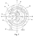
- FIG. 7 is a view similar to FIG. 3 , showing counterclockwise advance in the gear set and crank arm by one-half revolution, showing left extreme position.
- FIG. 8 is a front elevational view of a bodymaker in right extreme position similar to that shown in FIG. 3 , with gearbox housing closed, and showing a dual ram system attached to the crank arm and schematically showing typical accessory equipment to the operation of each ram.
- FIG. 9 is a view similar to FIG. 8 , showing advance in the crank arm by one-eighth counterclockwise revolution similar to that shown in FIG. 4 .
- FIG. 10 is a view similar to FIG. 8 , showing the crank arm advanced one-quarter counterclockwise revolution in the gear set similar to that shown in FIG. 5 .
- FIG. 11 is a view similar to FIG. 8 , showing advance in the crank arm by three-eighths counterclockwise revolution in the gear set similar to that shown in FIG. 6 .
- FIG. 12 is a view similar to FIG. 8 , showing advance in the crank arm by one-half counterclockwise revolution in the gear set similar to that shown in FIG. 7 and showing the bodymaker in left extreme position .
- FIG. 13 is a vertical cross-sectional view of the housing of the bodymaker drive system taken approximately at the plane of line 13 - 13 in FIG. 10 , with center spacer broken away for clarity and showing front, rear and internal shafts and planetary gear in side elevation.
- FIG. 14 is an isometric assembly view of the rotating components of a planetary gear carrier.
- FIG. 15 is a top plan view in partial section, showing input and output mechanisms of the bodymaker gearbox housing.
- FIG. 16 is a view similar to FIG. 13 , showing a modified embodiment wherein the ram output is central within the bodymaker gearbox housing.
- the invention is a can bodymaker generally indicated by the reference character 20 .
- the bodymaker provides a straight-line output to an output device for driving one or more rams along a straight-line path. Substantially all portions of the bodymaker operate in continuous rotary motion, from the motor that powers the bodymaker through the output of a rotary-to-linear converter.
- a crank pin or journal pin provides connection between the rotary-to-linear converter and one or more rams. As the crank pin moves, it tracks a straight-line path, although the crank pin is located on a continuously rotating mechanism and preserves the advantages of a rotating mechanism.
- the rotary-to-linear converter employs a hypocycloid gear train, also known as a hypocycloid straight-line mechanism.
- the drive system of can bodymaker is shown to include a gearbox 20 and is built on a gearbox base or supporting frame 22 .
- a motor 24 and a motion converter mechanism in a drive housing or gearbox housing 26 are mounted on or carried by the gearbox base frame 22 .
- the drive housing 26 may be configured as a cylindrical shell.
- the opposite open ends of the housing 26 which will be referred to as the front and rear faces of the housing, are partially closed at their periphery by annular retainer plates 27 .
- the retainer plates are removably fastened to the front and rear edges of housing 26 , such as by bolts. As best shown in FIG. 13 , the retainer plates retain of bearings within the housing.
- the retainer plates contain lubricant within the gearbox housing 26 and provide attachment points connecting the housing 26 to base 22 .
- the motor is operatively connected to provide rotary input that drives the motion converter, such as by a direct drive connection, through an intermediate system of gears and clutches, by roller chain and sprocket, by a drive belt 28 , or by any other suitable interconnection.
- a suitable input device for delivering rotation to the motion converter is an input shaft or main shaft 30 , FIG. 13 , which receives power to operate the motion converter.
- the main shaft may carry a belt sheave or pulley wheel 31 of variably selected size to carry a drive belt 28 from the motor 24 for adjusting the drive ratio between the motor 24 and motion converter mechanism in gearbox 26 .
- FIGS. 1 and 2 show internal operating portions of the motion converter to be two interacting rollers 32 , 34 .
- the housing 26 carries the major, ring shaped roller 32 with open center of preselected inner diameter.
- the major ring 32 may be attached to the housing and consequently to the base frame 22 in such a way that the major ring 32 is stationary or maintains in a fixed position with respect to the housing 26 and base frame 22 .
- the major ring 32 may be regarded as lying in an X-Y plane.
- the main shaft 30 operates on an axis, which may be regarded as being a Z-axis, concentric with the center point of the major ring 32 .
- the gearbox housing 26 supports main shaft 30 for rotation on the Z-axis with respect to the fixed housing 26 and major ring 32 .
- the main shaft carries an orbitable minor roller or planetary ring 34 in suitable position to roll around the inside circumference of the major ring 32 .
- the planetary ring 34 also may be regarded as lying in an X-Y plane, where it engages the inside circumference of major ring 32 , forming a hypocycloid straight-line mechanism.
- the planetary ring 34 is of preselected diameter that is one-half the preselected inside diameter of the major ring 32 .
- the term, “diameter,” refers to the effective measurement across each ring viewed as an imaginary rolling cylinder.
- major ring 32 is a ring gear
- orbiting ring 34 is a planetary gear.
- the diameter of intermeshing gears typically is measured at the pitch circle, near the midpoint of the gear teeth.
- a pitch surface can be defined as the surface of the imaginary rolling cylinder that each toothed gear may be considered to replace; and the pitch circle is a right section of the pitch surface.
- each gear has a pitch diameter taken across the pitch circle.
- the meshing of the two gears may be equated to the rolling of two cylinders in circumferential engagement, having the respective pitch diameters of the two gears.
- the ring gear and planetary gear have the gear ratio of 2:1.
- the two rollers or gears can be considered to engage at their circumferences taken at the pitch surface, where the ratio of their circumferences is 2:1.
- a planetary gear carrier supports the planetary gear 34 at a radial offset position with respect to the main shaft 30 .
- the planetary gear carrier supports the planetary gear at least from one side support, such as by rear hub 36 , and preferably from supports on both sides, such as between rear and front disk shaped hubs 36 , 46 .
- At least one of the hubs 36 , 46 is connected to main shaft 30 , from which the hub is driven by the rotation of the main shaft 30 .
- driven hub 36 is connected to the opposite hub 46 of the planetary gear carrier and causes all hubs and other connected components of the carrier to rotate in a pre-established alignment among the two hubs and the planetary gear.
- the planetary gear 34 rotates on a planetary gear axis that is parallel to the axis of the main shaft 30 and offset in a radial direction.
- the planetary gear axis is the longitudinal centerline axis of planetary gear shaft 40 , which extends from both the front and rear faces of the planetary gear 34 .
- Rear support hub 36 receives and carries the rear portion of shaft 40 for rotation in bearings 42 .
- the similar front hub 46 of the planetary gear carrier further described below, carries shaft 40 on the opposite or front face of gear 34 .
- Bearings 38 carry the rear hub 36 for rotation in gearbox housing 26 .
- the planetary gear can be regarded as being disposed in an X-Y plane, while the axis of shaft 40 is oriented as a Z-axis. As noted above, the shaft 40 extends from both front and rear faces of gear 34 . Bearings 42 carry the shaft 40 for rotation with respect to both front and rear hubs. Shaft 40 is parallel to main shaft 30 . The centerline of planetary gear shaft 40 is offset from the centerline of main shaft 30 by one-half the pitch diameter, i.e., the pitch radius, of the planetary gear 34 .
- the ring gear 32 and planetary gear 34 may be herringbone or double helical gears.
- two helical gears of opposite hand are located side-by-side to cancel resulting thrust forces.
- FIGS. 1 and 2 also show a combined axial spacer and counterbalance weight 44 carried at a radially offset position from gear 34 and supported at least from rear hub 36 to cancel vibrations due to the orbiting movement of the planetary gear 34 .
- FIGS. 1 and 2 Comparing FIGS. 1 and 2 provides an example of the initial operation of the motion converter between two opposite configurations.
- Motor 24 drives the motion converter, turning rear rotary hub 36 with respect to housing 26 .
- the direction of hub rotation may be counterclockwise in the view of FIGS. 1 and 2 .
- FIG. 1 shows the planetary gear 34 in an arbitrary starting position of rotation, which is preferred to be at a horizontal extreme position such as a right hand extreme position.
- Counterclockwise motion of rear hub 36 will move the planetary gear 34 through a first counterclockwise orbit or arc.
- a one-half rotation of the rotary hub 36 moves the planetary gear to the opposite extreme position, such as extreme left hand position in FIG. 2 .
- the engaged gear teeth of gears 32 and 34 have caused the planetary gear to rotate on planetary gear shaft 40 .
- the planetary gear has rotated one-half revolution on shaft 40 .
- FIGS. 3-7 show the motion converter in a next stage of assembly.
- a front rotary hub 46 of the planetary gear carrier is omitted in these illustrations, which continue to expose the gear set 32 , 34 .
- a completely assembled motion converter in gearbox 26 includes a front rotary hub 46 that is carried in housing 26 for rotation on bearings 48 .
- This front hub 46 carries a front end of the planetary gear shaft 40 .
- the rotary hub 46 also closes the front side of gearbox housing 26 .
- the front and rear rotary hubs are fastened together for synchronized rotation by any suitable fastening or alignment devices such as alignment pins, bolts 50 , or a combination of such fasteners and alignment devices.
- the gearbox housing 26 further may include front and rear rotary cover plates 52 that cover the front and rear rotary hubs 36 , 46 at the front and rear faces of the housing 26 .
- the cover plates may carry seals at their peripheral edges to further seal the gearbox housing 26 against loss of lubricant.
- FIG. 14 shows assembly of a planetary gear carrier mechanism that is the central rotary element of the bodymaker gearbox 20 .
- Planetary gear 34 and counterweight 44 occupy a central area of this assembly.
- the counterweight 44 is thicker than the planetary gear 34 , which permits the counterweight 44 to be clamped in place as a spacer that preserves the ability of the planetary gear 34 to rotate.
- Front rotary hub 46 and rear rotary hub 36 are clamped against the opposite faces of the counterweight-spacer 44 .
- Hubs 36 , 46 and counterweight 44 define aligned bores 81 . Suitable fasteners such as bolts 50 pass through the aligned bores 81 of the pair of rotary hubs 36 , 46 and counterweight 44 .
- the fasteners draw together the rotary hubs against the counterweight 44 .
- the fasteners 50 may be inserted through the front hub 46 and engage nuts 82 at the rear hub 36 , or fasteners 50 be threaded into the rear rotary hub.
- the rotary hubs 36 , 46 define counter bores 84 receiving the fastener heads and nuts within the thickness of the hubs 36 , 46 .
- the rotary hubs 36 , 46 define bores 86 receiving and carrying planetary gear shaft 40 on suitable bearings. A forward end of shaft 40 extends through the front rotary hub 46 to carry the crank arm 54 , as subsequently described.
- Components of the planetary gear carrier assembly in FIG. 14 are timed to each other and the planetary gear carrier is timed to the ring gear 32 .
- the elements of the planetary gear carrier are assembled solidly to eliminate torsional deflection between input and output sides of gearbox housing 26 .
- the planetary gear carrier forms a solid, block-like structure that is capable of resisting strong torsional forces.
- front and rear cover plates 52 are secured to the outer faces of the front and rear hubs 36 , 46 as portions of the block-like structure.
- the front cover plate 52 defines a through-bore 88 for passage of a front end of planetary gear shaft 40 through the front of housing 26 .
- the rear cover plate may define a closed bore 90 for receiving a rear end of shaft 40 or providing clearance from the read end of shaft 40 in hub 36 .
- Each cover plate 52 is secured to an outside face of the juxtaposed rotary hub 36 , 46 .
- a plurality of aligned bores 92 in cover plates 52 and hubs 36 , 46 permit each cover plate 52 to be aligned with the juxtaposed rotary hub in a predetermined rotational position.
- Fasteners such as bolts 94 or other alignment aids such as dowel pins are inserted into bores 92 to secure the cover plates to the rotary hubs in properly aligned positions.
- Each bolt 94 may secure a cover plate to the outer face of a rotary hub by threaded reception in a bore 92 of the respective hub.
- FIGS. 3-7 show the addition of a crank arm 54 that lies forward of the front rotary hub 46 and front cover plate 52 .
- Crank arm 54 is mounted on the front protrusion of planetary gear shaft 40 through front cover plate 52 .
- the crank arm 54 is attached to shaft 40 is a predetermined, aligned position with respect to planetary gear 34 .
- the crank arm 54 may be secured to the shaft 40 by a wedge fastener 55 , FIG. 13 , by a laser weld, or by any other suitable means securing the crank arm in a fixed position with respect to the pitch circle of gear 34 .
- the crank arm 54 is an output device that rotates with shaft 40 while at least one point of the rotating arm tracks a straight-line that overlies a pitch diameter of the ring gear 32 .
- the relative rotational position of the crank arm on shaft 40 determines the path of the line or selection of the pitch diameter that the straight-line point will track.
- a desirable relative orientation of the crank arm 54 on shaft 40 establishes a horizontal pitch diameter or X-axis to be tracked by the straight-line point.
- the presence of the straight-line tracking point on the rotary crank arm completes an entirely rotary transmission sequence, while providing at least the single point following a straight-line path. This one point allows a bodymaker ram to be attached to the crank arm 54 to be driven with straight-line motion.
- the output device may be a connecting point on the crank arm for attaching the ram.
- the output device may further include a connecting device such as a journal pin 56 that swings through an arc on a radius of the planetary gear pitch circle as the crank arm rotates with shaft 40 .
- the output device should be configured for motion about a Z-axis through the straight-line tracking point, which is parallel to and offset from the Z-axis of the planetary gear.
- the output device is aligned with a point on the pitch circle of the planetary gear 34 .
- Either a male or female output component is suitable, as the ram can be equipped with a complementary male or female element that mates or attaches to the output device along the Z-axis of the straight-line tracking point.
- crank pin or journal pin 56 that extends longitudinally on a Z-axis from crank arm 54 .
- the crank pin 56 may be fixed to the crank arm by a press-fit or other technique so that the pin 56 is in fixed position with respect to the crank arm.
- a central longitudinal axis of crank pin 56 passes through the straight-line tracking point on the crank arm 54 .
- the central longitudinal axis of crank pin 56 is spaced from the central longitudinal axis of planetary gear shaft 40 by the pitch radius of the planetary gear 34 .
- the central axis of crank pin 56 is aligned with a fixed point on the circumference or pitch circle of planetary gear 34 and rotates in synchronization with the planetary gear.
- This relationship will be referred to as being aligned with a point on the pitch circle of the planetary gear.
- An aligned output device such as pin 56 may be carried at a Z-axis position removed from the X-Y plane of planetary gear 34 . Nevertheless, the Z-axis of the output device, such as pin 56 , is perpendicular to the X-Y or major plane of the planetary gear 34 and tracks the motion of a point on the pitch circle or circumference of planetary gear 34 .
- the crank pin 56 provides a means for attaching one or more rams of the bodymaker 20 at a laterally offset position from the X-Y plane of the planetary gear.
- the placement of the crank arm 54 in front of rotary hub 46 and front cover plate 52 enables shaft 40 to be supported in bearings on both sides of planetary gear 34 to withstand the high forces transmitted through a bodymaker ram.
- the crank pin 56 carries a ram journal connector 58 on bearings 59 .
- the fixed connection to the crank arm 54 allows the crank pin 56 to remain stationary with respect to the crank arm 54 .
- the arrangement of bearings 59 allows the ram journal connection 58 to move in straight-line motion on an X-axis.
- FIG. 3 again shows the planetary gear 34 in extreme right position, similar to FIG. 1 .
- the crank arm 54 extends further in the extreme direction, to the right according to the orientation of FIG. 3 .
- Due to the position of crank pin 56 at the pitch circle of gears 32 , 34 in the extreme orientation of FIG. 3 the axis of crank pin 56 lies directly over the pitch circle of ring gear 32 .
- the crank pin 56 overlies one end of a preselected pitch diameter of the ring gear.
- FIGS. 3-7 show an XYZ coordinate system in which the X-axis, X-X, overlies and is parallel to the selected pitch diameter of the ring gear.
- Axis X-X typically is a horizontal axis.
- the Y-axis, Y-Y is perpendicular to the X-axis and typically is the vertical axis.
- the Z-axis can be regarded as extending perpendicular to the plane of FIG. 3 .
- the orientation of the crank arm 54 can be described by the position of the Z-axis through crank pin 56 with respect to the Z-axis of planetary gear shaft 40 .
- FIGS. 4-7 show the progressive advancement of the crank pin 56 as the planetary gear 34 rolls around ring gear 32 .
- crank arm 54 and planetary gear 34 have advanced through a counterclockwise arc or orbit of one-eighth revolution with respect to the ring gear 32 .
- the planetary gear 34 rotates on shaft 40 in the opposite or clockwise direction.
- the planetary gear 34 and crank arm 54 both have rotated clockwise by one-eighth revolution with respect to shaft 40 .
- the crank pin 56 has shifted radially toward the center point of the main shaft 30 while tracking the straight-line axis X-X.
- crank arm 54 has advanced by an additional one-eighth revolution for a total arc of one-quarter circle from the position of FIG. 3 .
- FIG. 5 shows that the crank arm now is parallel to axis Y-Y.
- Crank pin 56 continues to track the selected pitch diameter along axis X-X and now is at the midpoint of that pitch diameter.
- FIG. 6 shows the position of the crank arm 54 after a further one-eighth revolution.
- the crank pin 56 continues to track the selected pitch diameter and tracks axis X-X.
- crank arm 54 is shown after advancing through a total arc of one-half circle.
- the crank arm 54 extends horizontally to the left and the crank pin 56 lies over the left or opposite end of the selected pitch diameter, relative to the position of FIG. 3 .
- the connection means 56 followed the straight line of axis X-X.
- the planetary gear 34 can continue through another arc of one-half circle to bring the crank arm back to the position of FIG. 3 .
- the central axis of crank pin 56 will continue to track the true straight line of the selected pitch diameter, as exemplified by axis X-X.
- the motion of the straight-line tracking point exemplified by a centerpoint of pin 56 in FIGS. 3-7 includes no vertical or Y-axis component.
- FIGS. 8-12 show the same progression of motion as in FIGS. 3-7 .
- These figures show the gearbox 20 with front plate 52 in place.
- Front rotary hub 46 supports shaft 40 within the gearbox.
- Front plate 52 and retainer plate 27 close the front face of the gearbox 20 .
- Crank pin 56 is shown in its preferred embodiment to be a ram-connecting journal shaft 56 longitudinally aligned with a Z-axis that is parallel to planetary gear shaft 40 and main shaft 30 .
- a journal box such as rotary junction 58 or other complementary structure on pin 56 mounts at least one punch or ram 60 for straight-line motion on an X-axis such as axis X-X.
- the elongated ram is supported with respect to a ram support base 72 in a linear bearing 62 , which may be a hydrostatic bearing, magnetic bearing, or the like.
- the ram is aligned with a redraw sleeve 63 and adjacent a tool pack housing 64 , both schematically indicated.
- the redraw sleeve 63 travels along an axis that is parallel to the ram 60 and movable for longitudinal motion on an X-axis independently of the ram.
- the tool pack housing 64 encloses a series of ironing dies through which the ram pushes a work piece such as a preformed cup of metal, plastic, composite, polymer co-extruded laminate material, or other materials. The dies iron the preformed cup to produce a can body.
- the redraw mechanism 63 and tool pack 64 typically are served by a cup infeed device, schematically shown at 74 , and a can discharge device and domer sub-assembly, schematically shown at 76 .
- FIG. 8 shows the ram 60 in fully withdrawn position, with crank pin 56 at right extreme position.
- the bodymaker 20 employs double action by powering two rams, each extending in an opposite direction.
- FIG. 8 also shows a fully advanced, opposite ram 66 supported in linear bearing 68 , advanced through redraw sleeve 69 and tool pack 70 .
- the redraw mechanism 69 and tool pack 70 also are served by a cup infeed device, schematically shown at 78 , and a can discharge device and domer sub-assembly, schematically shown at 80 .
- Ram support structure 72 carries the various respective bearings, redraw sleeves, and tool packs.
- Ram support structure 72 also supports the gearbox and motor base 22 , establishing a base structure in which the gearbox, rams, and other components can be aligned as necessary for proper operation.
- the ram components are arranged along an X-axis in alignment with an associated ram.
- the two rams 60 , 66 may operate either on common axis or on parallel, offset axes perpendicular to the Z-axis of crank pin 56 and parallel to an X-axis.
- FIGS. 9-12 show the two rams of a dual-action bodymaker completing one stroke each in opposite phase, with ram 60 showing the forward stroke and ram 66 showing the reverse stroke.
- FIG. 9 shows ram 60 advancing linearly and ram 66 withdrawing linearly as crank arm 54 turns through one-eighth revolution.
- FIG. 10 the rams are at mid-stroke and the crank arm 54 is perpendicular to a longitudinal axis of each ram.
- FIG. 11 shows the rams moved through three-eighths of a stroke.
- FIG. 12 shows ram 60 at the completion of the forward stroke and ram 66 at the completion of the reverse stroke.
- FIG. 15 shows details of the input and output mechanisms of the bodymaker 20 in a partial top view of the bodymaker taken approximately from the view of FIG. 8 .
- the input side at the left of the drawing view illustrates a drive belt 28 engaging a sheave 31 that is fixed on input shaft 30 .
- the input shaft 30 carries an accessory operator that could be used to actuate a mechanical redraw device, if desired.
- the accessory operator includes an opposed pair of elongated actuator shafts 106 that are connected to an eccentric hub 108 on the input shaft 30 .
- the eccentricity of hub 108 alternately extends and retracts each actuator shaft 106 .
- the actuator shafts 106 can perform any accessory function to the operation of the bodymaker.
- the input shaft 30 carries a counterbalance 100 , shown also in FIG. 13 .
- This counterbalance damps vibration at the input shaft 30 .
- FIG. 13 additionally shows a counterbalance 102 fixed to the output shaft 40 or to the crank arm 54 .
- the counterbalance 102 preferably is a pendulum counterbalance and damps vibration at the output side of the bodymaker. Additional counterbalance devices and vibration dampers may be applied to the bodymaker as required, according to known techniques.
- the output shaft 40 carries crank arm 54 in fixed relationship.
- Journal 56 extends parallel to output shaft 40 and carries the journal connection 58 on bearings 59 , as previously described in connection with FIG. 13 .
- the journal connections 58 provide a central journal connection to ram 60 nested between the double or forked journal connections to ram 66 .
- Each ram is provided with an enlarged head 98 that fits closely within a holder 95 .
- a ram stub 97 extends from each holder 95 into a bellows coupling 96 .
- the bellows couplings 96 absorb minor parallel misalignment or angular misalignment while transmitting axial motion.
- the rams 60 , 66 extend outward from the respective bellows couplings.
- bodymaker gearbox 20 provides input at one face of gearbox housing 26 and output at the opposite face of the gearbox housing 26 .
- This arrangement supports the hypocycloid drive system from one side of the ram system.
- FIG. 16 An alternative embodiment provides input on either one or two faces of bodymaker gearbox 20 ′, best shown in FIG. 16 .
- Output is from a center of the gearbox housing 26 .
- FIG. 16 most components are given the same numbers used for the same or nearly equivalent part in FIGS. 1-15 .
- the ring gear 32 and planetary gear 34 are shown on the right or rear side of the view, with an additional ring gear 32 ′ and planetary gear 34 ′ of opposite hand shown on the left or front side of the view.
- the front and rear planetary gears 34 , 34 ′ each carries a corresponding front or rear crank arm 54 near the center of the gearbox housing 26 .
- a central crank pin 56 connects the front and rear crank arms 54 at the center of the housing 26 and carries the journal connections 58 .
- the front and rear crank arms 54 and central crank pin 56 are joined to form a rigid connection between planetary gears 34 and 34 ′.
- the gearbox housing 26 defines passage windows 104 at ends of the preselected straight-line diameter that allow the rams to operate from the central position of crank pin 56 .
- Bodymaker gearbox 20 ′ provides an input shaft 30 at either one or both faces. If driven from only one side, such as from the rear side, a rear input shaft 30 drives rear hub 36 , in turn orbiting rear planetary gear 34 as similarly described in connection with FIGS. 1-15 .
- the planetary gear 34 drives its associated rear side crank arm 54 and crank pin 56 .
- the opposite equivalent structures, such as front crank arm 54 , front planetary gear 34 ′, and front hub 46 are driven from the rear side input through the crank pin 56 . This arrangement supports the crank pin 56 from both front and rear ends.
- Bodymaker gearbox 20 ′ can be driven from both faces by applying synchronized drive systems to both the front and rear input shafts 30 of FIG. 16 . If it is not desired to drive both input shafts 30 , the unused input shaft 30 need not be installed.
- a bodymaker gearbox 20 , 20 ′ constructed according to the invention has a potential production ability that is substantially greater than other known bodymakers.
- Bodymaker 20 , 20 ′ can operate with improved linear stability of the ram, enabled by the output driving force component being coaxial or concentric to the ram, itself. This will allow high-speed operation and a low rejection rate due to defective can bodies. These advantages may enable the use of less metal or other material to form each can body.
- the centerlines of ring gears 32 , 32 ′, planetary gears 34 , 34 ′, and crank pin 56 are initially aligned in a perpendicular plane to the desired straight-line.
- the indicated centerlines are initially arranged in a vertical plane. This initial alignment is as shown in FIGS. 5 and 10 , where the vertical plane is a YZ plane extending perpendicular to the view. The elements are arranged such that their centerlines lie in the same YZ plane.
- crank pin 56 This initial arrangement will result in a horizontal path of displacement for crank pin 56 , with a coaxial relationship with rams 60 , 66 .
- a minute amount of misalignment between the crank pin 56 and rams 60 , 66 can be absorbed through the connecting members 95 , 96 , as mentioned above.
- crank arm following a linear path along a horizontal diameter or between horizontal extreme positions, such as right and left extreme positions.
- This particular orientation may be the commercially practical choice.
- the requirements of a particular installation may favor a differently angled axis for straight-line operations.
- directions of movement, angles of movement, and directions of rotation are for purposes of description and not limitation.
Landscapes
- Engineering & Computer Science (AREA)
- Mechanical Engineering (AREA)
- Transmission Devices (AREA)
- Retarders (AREA)
Abstract
Description
Claims (9)
Priority Applications (3)
| Application Number | Priority Date | Filing Date | Title |
|---|---|---|---|
| US11/309,514 US7434442B2 (en) | 2006-08-16 | 2006-08-16 | Container bodymaker |
| US11/838,888 US7882721B2 (en) | 2006-08-16 | 2007-08-15 | Container bodymaker |
| PCT/US2007/076054 WO2008022229A2 (en) | 2006-08-16 | 2007-08-16 | Container bodymaker |
Applications Claiming Priority (1)
| Application Number | Priority Date | Filing Date | Title |
|---|---|---|---|
| US11/309,514 US7434442B2 (en) | 2006-08-16 | 2006-08-16 | Container bodymaker |
Related Child Applications (1)
| Application Number | Title | Priority Date | Filing Date |
|---|---|---|---|
| US11/838,888 Continuation-In-Part US7882721B2 (en) | 2006-08-16 | 2007-08-15 | Container bodymaker |
Publications (2)
| Publication Number | Publication Date |
|---|---|
| US20080041132A1 US20080041132A1 (en) | 2008-02-21 |
| US7434442B2 true US7434442B2 (en) | 2008-10-14 |
Family
ID=39083122
Family Applications (2)
| Application Number | Title | Priority Date | Filing Date |
|---|---|---|---|
| US11/309,514 Active - Reinstated US7434442B2 (en) | 2006-08-16 | 2006-08-16 | Container bodymaker |
| US11/838,888 Expired - Fee Related US7882721B2 (en) | 2006-08-16 | 2007-08-15 | Container bodymaker |
Family Applications After (1)
| Application Number | Title | Priority Date | Filing Date |
|---|---|---|---|
| US11/838,888 Expired - Fee Related US7882721B2 (en) | 2006-08-16 | 2007-08-15 | Container bodymaker |
Country Status (2)
| Country | Link |
|---|---|
| US (2) | US7434442B2 (en) |
| WO (1) | WO2008022229A2 (en) |
Cited By (11)
| Publication number | Priority date | Publication date | Assignee | Title |
|---|---|---|---|---|
| US20090023546A1 (en) * | 2005-02-28 | 2009-01-22 | Dayco Europe S.R.L. | Friction Wheel Actuator |
| US20090193914A1 (en) * | 2008-02-01 | 2009-08-06 | William Lake | Torque Transfer Device |
| US20110214473A1 (en) * | 2010-03-05 | 2011-09-08 | Hinterkopf Gmbh | Forming Device |
| US20130216334A1 (en) * | 2012-02-22 | 2013-08-22 | Suzhou Slac Precision Equipment Co.,Ltd. | Dual double-action can body maker |
| US20150068268A1 (en) * | 2013-09-11 | 2015-03-12 | Stolle Machinery Company, Llc | Actuator with variable speed servo motor for redraw assembly |
| US20150266251A1 (en) * | 2014-03-21 | 2015-09-24 | Schuler Pressen Gmbh | Drive device with a hypocycloid gear assembly for a forming machine |
| US10343208B2 (en) * | 2013-03-12 | 2019-07-09 | Stolle Machinery Company, Llc | Operating mechanism for a vertically oriented bodymaker |
| USD933108S1 (en) * | 2020-06-02 | 2021-10-12 | Stolle Machinery Company, Llc | Frame member |
| WO2021242358A1 (en) * | 2020-05-28 | 2021-12-02 | Stolle Machinery Company, Llc | Cam driven multi-output bodymaker |
| US20220016690A1 (en) * | 2020-07-20 | 2022-01-20 | Universal Can Corporation | Can body maker and frame for drive mechanism |
| US20230081092A1 (en) * | 2020-05-28 | 2023-03-16 | Stolle Machinery Company, Llc | Forming assembly for bodymaker and bodymaker including same |
Families Citing this family (32)
| Publication number | Priority date | Publication date | Assignee | Title |
|---|---|---|---|---|
| PL2069090T3 (en) * | 2006-09-28 | 2010-07-30 | Crown Packaging Tech | Bodymaker ram attachment |
| JP5100073B2 (en) * | 2006-09-28 | 2012-12-19 | 村田機械株式会社 | Linear motor device and machine tool equipped with the same |
| JP2008157161A (en) * | 2006-12-26 | 2008-07-10 | Kanzaki Kokyukoki Mfg Co Ltd | Multi-pump unit and vehicle equipped with multi-pump unit |
| US8894530B1 (en) * | 2009-04-27 | 2014-11-25 | Thomas M. Read | Hypocycloidal crank apparatus |
| US10137490B2 (en) | 2013-08-28 | 2018-11-27 | Stolle Machinery Company, Llc | Outboard hydrostatic bearing assembly for can bodymaker |
| JP6250168B2 (en) * | 2013-08-28 | 2017-12-20 | ストール マシーナリ カンパニー, エルエルシーStolle Machinery Company, LLC | Outboard guide bearing assembly, ram assembly and can body making machine |
| BR112017004983A2 (en) * | 2014-10-08 | 2017-12-05 | Nestec Sa | beverage extraction machine extraction unit |
| US10076376B2 (en) | 2015-05-27 | 2018-09-18 | Medos International Sàrl | Devices and methods for bending or cutting implants |
| CN112371821B (en) * | 2016-01-12 | 2023-05-05 | 斯多里机械有限责任公司 | Outboard hydrostatic support assembly for can bodymaker |
| US10194957B2 (en) * | 2016-05-13 | 2019-02-05 | Medos International Sarl | Devices and methods for bending or cutting implants |
| JP6789052B2 (en) * | 2016-09-30 | 2020-11-25 | ユニバーサル製缶株式会社 | Reciprocating linear motion mechanism and can molding equipment |
| JP2018095113A (en) * | 2016-12-14 | 2018-06-21 | トヨタ紡織株式会社 | Drive device |
| JP2018100046A (en) * | 2016-12-21 | 2018-06-28 | トヨタ紡織株式会社 | Driving device |
| US10940655B2 (en) | 2017-04-25 | 2021-03-09 | Stolle Machinery Company, Llc | Adjustable crankshaft eccentric for bodymaker ram stroke change |
| US10744550B2 (en) | 2017-04-25 | 2020-08-18 | Stolle Machinery Company, Llc | Eccentric second connecting rod subassembly |
| JP7101783B2 (en) * | 2017-12-21 | 2022-07-15 | ストール マシーナリ カンパニー,エルエルシー | Adjustable crankshaft eccentric mechanism for body maker ram stroke changes |
| US10589334B2 (en) | 2018-01-03 | 2020-03-17 | Stolle Machinery Company, Llc | Dampening assembly for can bodymaker ram |
| CN108705016A (en) * | 2018-04-28 | 2018-10-26 | 芜湖凯德机械制造有限公司 | A kind of two-sided automatic forging equipment of double-station Rectangular Parts |
| CN108730546B (en) * | 2018-08-24 | 2023-12-12 | 南京威普粉体工程有限公司 | Double-gate valve capable of forcing valve disc to rotate |
| CN110877069B (en) * | 2019-11-11 | 2020-12-11 | 苏州斯莱克精密设备股份有限公司 | High-speed balanced two-way double-punch tank stretching machine |
| CN110936365B (en) * | 2019-12-18 | 2021-05-25 | 北京航空航天大学 | Adjustable Stiffness Actuator Based on Reconstructed Adjustable Length Guide Rod Mechanism |
| US20210231172A1 (en) * | 2020-01-24 | 2021-07-29 | Katerra Inc. | Nested double eccentric anchor bolt bushings |
| US11666961B2 (en) | 2020-05-28 | 2023-06-06 | Stolle Machinery Company, Llc | Cam follower assembly for can bodymaker and can bodymaker including same |
| US11766711B2 (en) | 2020-05-28 | 2023-09-26 | Stolle Machinery Company, Llc | Redraw assembly for bodymaker |
| US11511332B2 (en) * | 2020-05-28 | 2022-11-29 | Stolle Machinery Company, Llc | Cam driven bodymaker |
| US11897020B2 (en) * | 2020-07-20 | 2024-02-13 | Universal Can Corporation | Reciprocating linear motion mechanism for can body maker and can body maker |
| JP7542346B2 (en) | 2020-07-20 | 2024-08-30 | アルテミラ製缶株式会社 | Reciprocating linear motion mechanism for can forming device and can forming device |
| JP7475230B2 (en) * | 2020-07-20 | 2024-04-26 | アルテミラ製缶株式会社 | Reciprocating linear motion mechanism for can forming device and can forming device |
| US11980927B2 (en) | 2020-07-20 | 2024-05-14 | Universal Can Corporation | Reciprocating linear motion mechanism for can body maker and can body maker |
| JP7542348B2 (en) * | 2020-07-20 | 2024-08-30 | アルテミラ製缶株式会社 | Reciprocating linear motion mechanism for can forming device and can forming device |
| JP7462501B2 (en) | 2020-07-20 | 2024-04-05 | アルテミラ製缶株式会社 | Reciprocating linear motion mechanism for can forming device and can forming device |
| JP7479240B2 (en) | 2020-08-06 | 2024-05-08 | アルテミラ製缶株式会社 | Reciprocating linear motion mechanism for can forming device and can forming device |
Citations (12)
| Publication number | Priority date | Publication date | Assignee | Title |
|---|---|---|---|---|
| US3696657A (en) | 1970-11-19 | 1972-10-10 | Coors Porcelain Co | Metal working crank and slide press mechanism |
| US3848472A (en) * | 1973-06-04 | 1974-11-19 | Gulf & Western Mfg Co | Cycloid press |
| US4096763A (en) * | 1976-12-22 | 1978-06-27 | General Motors Corporation | Hypocycloidal reduction gearing |
| US4137749A (en) * | 1976-10-23 | 1979-02-06 | Textima Ag | Metalworking press |
| US4173138A (en) | 1977-10-28 | 1979-11-06 | Standun, Inc. | Can bodymaker having improved ram support and drive |
| US4934167A (en) | 1987-07-01 | 1990-06-19 | Adolph Coors Company | Can body making apparatus |
| US4956990A (en) | 1989-09-05 | 1990-09-18 | Adolph Coors Company | Apparatus for forming can bodies |
| US5257523A (en) | 1990-09-07 | 1993-11-02 | Coors Brewing Company | Can body maker with magnetic ram bearing and redraw actuator |
| US5335532A (en) | 1992-06-16 | 1994-08-09 | Aluminum Company Of America | Body maker apparatus |
| US5546785A (en) | 1995-05-05 | 1996-08-20 | Aluminum Company Of America | Crank mechanism for can body maker apparatus |
| US5564300A (en) | 1993-12-28 | 1996-10-15 | Aluminum Company Of America | Ram guidance mechanism for can body maker apparatus |
| US5735165A (en) | 1995-06-23 | 1998-04-07 | The Minster Machine Company | Bodymaker drive system |
Family Cites Families (2)
| Publication number | Priority date | Publication date | Assignee | Title |
|---|---|---|---|---|
| US3907470A (en) * | 1971-08-19 | 1975-09-23 | Hohenzollern Huettenverwalt | Gear machine |
| US4996865A (en) * | 1990-01-05 | 1991-03-05 | Reynolds Metals Company | Apparatus for forming one-piece metal can bodies |
-
2006
- 2006-08-16 US US11/309,514 patent/US7434442B2/en active Active - Reinstated
-
2007
- 2007-08-15 US US11/838,888 patent/US7882721B2/en not_active Expired - Fee Related
- 2007-08-16 WO PCT/US2007/076054 patent/WO2008022229A2/en not_active Ceased
Patent Citations (12)
| Publication number | Priority date | Publication date | Assignee | Title |
|---|---|---|---|---|
| US3696657A (en) | 1970-11-19 | 1972-10-10 | Coors Porcelain Co | Metal working crank and slide press mechanism |
| US3848472A (en) * | 1973-06-04 | 1974-11-19 | Gulf & Western Mfg Co | Cycloid press |
| US4137749A (en) * | 1976-10-23 | 1979-02-06 | Textima Ag | Metalworking press |
| US4096763A (en) * | 1976-12-22 | 1978-06-27 | General Motors Corporation | Hypocycloidal reduction gearing |
| US4173138A (en) | 1977-10-28 | 1979-11-06 | Standun, Inc. | Can bodymaker having improved ram support and drive |
| US4934167A (en) | 1987-07-01 | 1990-06-19 | Adolph Coors Company | Can body making apparatus |
| US4956990A (en) | 1989-09-05 | 1990-09-18 | Adolph Coors Company | Apparatus for forming can bodies |
| US5257523A (en) | 1990-09-07 | 1993-11-02 | Coors Brewing Company | Can body maker with magnetic ram bearing and redraw actuator |
| US5335532A (en) | 1992-06-16 | 1994-08-09 | Aluminum Company Of America | Body maker apparatus |
| US5564300A (en) | 1993-12-28 | 1996-10-15 | Aluminum Company Of America | Ram guidance mechanism for can body maker apparatus |
| US5546785A (en) | 1995-05-05 | 1996-08-20 | Aluminum Company Of America | Crank mechanism for can body maker apparatus |
| US5735165A (en) | 1995-06-23 | 1998-04-07 | The Minster Machine Company | Bodymaker drive system |
Cited By (21)
| Publication number | Priority date | Publication date | Assignee | Title |
|---|---|---|---|---|
| US8206255B2 (en) * | 2005-02-28 | 2012-06-26 | Dayco Europe S.R.L. | Friction wheel actuator |
| US20090023546A1 (en) * | 2005-02-28 | 2009-01-22 | Dayco Europe S.R.L. | Friction Wheel Actuator |
| US20090193914A1 (en) * | 2008-02-01 | 2009-08-06 | William Lake | Torque Transfer Device |
| US7794346B2 (en) * | 2008-02-01 | 2010-09-14 | William Lake | Torque transfer device |
| US20110214473A1 (en) * | 2010-03-05 | 2011-09-08 | Hinterkopf Gmbh | Forming Device |
| US8997544B2 (en) * | 2010-03-05 | 2015-04-07 | Hinterkopf Gmbh | Forming device |
| US9162274B2 (en) * | 2012-02-22 | 2015-10-20 | Suzhou SLAC Precision Equipment Co., Ltd. | Dual double-action can body maker |
| US20130216334A1 (en) * | 2012-02-22 | 2013-08-22 | Suzhou Slac Precision Equipment Co.,Ltd. | Dual double-action can body maker |
| US10343208B2 (en) * | 2013-03-12 | 2019-07-09 | Stolle Machinery Company, Llc | Operating mechanism for a vertically oriented bodymaker |
| US9352375B2 (en) * | 2013-09-11 | 2016-05-31 | Stolle Machinery Company, Llc | Actuator with variable speed servo motor for redraw assembly |
| US10220429B2 (en) | 2013-09-11 | 2019-03-05 | Stolle Machinery Company, Llc | Actuator with variable speed servo motor for redraw assembly |
| US20150068268A1 (en) * | 2013-09-11 | 2015-03-12 | Stolle Machinery Company, Llc | Actuator with variable speed servo motor for redraw assembly |
| US11033946B2 (en) | 2013-09-11 | 2021-06-15 | Stolle Machinery Company, Llc | Actuator with variable speed servo motor for redraw assembly |
| US20150266251A1 (en) * | 2014-03-21 | 2015-09-24 | Schuler Pressen Gmbh | Drive device with a hypocycloid gear assembly for a forming machine |
| US9636880B2 (en) * | 2014-03-21 | 2017-05-02 | Schuler Pressen Gmbh | Drive device with a hypocycloid gear assembly for a forming machine |
| WO2021242358A1 (en) * | 2020-05-28 | 2021-12-02 | Stolle Machinery Company, Llc | Cam driven multi-output bodymaker |
| US11338351B2 (en) * | 2020-05-28 | 2022-05-24 | Stolle Machinery Company, Llc | Cam driven multi-output bodymaker |
| US20230081092A1 (en) * | 2020-05-28 | 2023-03-16 | Stolle Machinery Company, Llc | Forming assembly for bodymaker and bodymaker including same |
| US12257619B2 (en) * | 2020-05-28 | 2025-03-25 | Stolle Machinery Company, Llc | Forming assembly for bodymaker and bodymaker including same |
| USD933108S1 (en) * | 2020-06-02 | 2021-10-12 | Stolle Machinery Company, Llc | Frame member |
| US20220016690A1 (en) * | 2020-07-20 | 2022-01-20 | Universal Can Corporation | Can body maker and frame for drive mechanism |
Also Published As
| Publication number | Publication date |
|---|---|
| WO2008022229B1 (en) | 2008-07-03 |
| WO2008022229A3 (en) | 2008-05-02 |
| US20080041132A1 (en) | 2008-02-21 |
| WO2008022229A2 (en) | 2008-02-21 |
| US20080041133A1 (en) | 2008-02-21 |
| US7882721B2 (en) | 2011-02-08 |
Similar Documents
| Publication | Publication Date | Title |
|---|---|---|
| US7434442B2 (en) | Container bodymaker | |
| EP3831591A1 (en) | Horizontal high-speed paper cup/paper bowl forming machine | |
| US5467628A (en) | Can bottom reprofiler | |
| JPS6366623B2 (en) | ||
| US6477945B1 (en) | Double-action mechanical press | |
| US5826479A (en) | Cutting device | |
| WO2021242361A1 (en) | Forming assembly for bodymaker and bodymaker including same | |
| US4229963A (en) | Machine for noncutting metal shaping | |
| CN100486723C (en) | Reciprocatting type pipe mill with long stroke | |
| CN1017783B (en) | Multi-station die rotary high-speed cold header | |
| US6240794B1 (en) | Crank assembly | |
| US4956990A (en) | Apparatus for forming can bodies | |
| JP4169146B2 (en) | Crank press machine | |
| US5735165A (en) | Bodymaker drive system | |
| WO2021242360A1 (en) | Cam follower assembly for can bodymaker and can bodymaker including same | |
| EP4157560A1 (en) | Cam driven bodymaker | |
| CN107351433A (en) | A kind of jumper bar drive mechanism of metal can body forming machine | |
| JPH04228295A (en) | Press machine | |
| CN214214836U (en) | High-speed stamping press | |
| CN117181978A (en) | One shot forming's transformer housing cold forging equipment | |
| JP7540008B2 (en) | Redraw Assembly for Bodymaker | |
| US5134874A (en) | Method for performing work | |
| CN112620474A (en) | Double-acting stamping movement mechanism | |
| EP4157559A1 (en) | Cam driven multi-output bodymaker | |
| CN112519289A (en) | High-speed stamping press |
Legal Events
| Date | Code | Title | Description |
|---|---|---|---|
| AS | Assignment |
Owner name: WERTH PACKAGING, LLC, COLORADO Free format text: ASSIGNMENT OF ASSIGNORS INTEREST;ASSIGNOR:GOMBAS, LASZLO A.;REEL/FRAME:018131/0884 Effective date: 20060814 |
|
| AS | Assignment |
Owner name: WERTH ADVANCED PACKAGING INNOVATIONS, LTD, COLORAD Free format text: ASSIGNMENT OF ASSIGNORS INTEREST;ASSIGNOR:WERTH PACKAGING, LLC;REEL/FRAME:019927/0909 Effective date: 20070814 |
|
| STCF | Information on status: patent grant |
Free format text: PATENTED CASE |
|
| FEPP | Fee payment procedure |
Free format text: PETITION RELATED TO MAINTENANCE FEES GRANTED (ORIGINAL EVENT CODE: PMFG); ENTITY STATUS OF PATENT OWNER: LARGE ENTITY Free format text: PETITION RELATED TO MAINTENANCE FEES FILED (ORIGINAL EVENT CODE: PMFP); ENTITY STATUS OF PATENT OWNER: LARGE ENTITY |
|
| REMI | Maintenance fee reminder mailed | ||
| PRDP | Patent reinstated due to the acceptance of a late maintenance fee |
Effective date: 20121107 |
|
| FPAY | Fee payment |
Year of fee payment: 4 |
|
| SULP | Surcharge for late payment | ||
| FPAY | Fee payment |
Year of fee payment: 8 |
|
| SULP | Surcharge for late payment |
Year of fee payment: 7 |
|
| AS | Assignment |
Owner name: SCI, LLLP, COLORADO Free format text: ASSIGNMENT OF ASSIGNORS INTEREST;ASSIGNOR:WERTH ADVANCED PACKAGING INNOVATIONS, LTD.;REEL/FRAME:046476/0549 Effective date: 20180613 |
|
| FEPP | Fee payment procedure |
Free format text: MAINTENANCE FEE REMINDER MAILED (ORIGINAL EVENT CODE: REM.); ENTITY STATUS OF PATENT OWNER: SMALL ENTITY |
|
| FEPP | Fee payment procedure |
Free format text: ENTITY STATUS SET TO UNDISCOUNTED (ORIGINAL EVENT CODE: BIG.); ENTITY STATUS OF PATENT OWNER: LARGE ENTITY |
|
| FEPP | Fee payment procedure |
Free format text: 11.5 YR SURCHARGE- LATE PMT W/IN 6 MO, LARGE ENTITY (ORIGINAL EVENT CODE: M1556); ENTITY STATUS OF PATENT OWNER: LARGE ENTITY |
|
| MAFP | Maintenance fee payment |
Free format text: PAYMENT OF MAINTENANCE FEE, 12TH YEAR, LARGE ENTITY (ORIGINAL EVENT CODE: M1553); ENTITY STATUS OF PATENT OWNER: LARGE ENTITY Year of fee payment: 12 |