JP6250168B2 - Outboard guide bearing assembly, ram assembly and can body making machine - Google Patents
Outboard guide bearing assembly, ram assembly and can body making machine Download PDFInfo
- Publication number
- JP6250168B2 JP6250168B2 JP2016537840A JP2016537840A JP6250168B2 JP 6250168 B2 JP6250168 B2 JP 6250168B2 JP 2016537840 A JP2016537840 A JP 2016537840A JP 2016537840 A JP2016537840 A JP 2016537840A JP 6250168 B2 JP6250168 B2 JP 6250168B2
- Authority
- JP
- Japan
- Prior art keywords
- assembly
- ram
- bearing assembly
- component
- bearing
- Prior art date
- Legal status (The legal status is an assumption and is not a legal conclusion. Google has not performed a legal analysis and makes no representation as to the accuracy of the status listed.)
- Active
Links
- 230000008878 coupling Effects 0.000 claims description 131
- 238000010168 coupling process Methods 0.000 claims description 131
- 238000005859 coupling reaction Methods 0.000 claims description 131
- 239000012530 fluid Substances 0.000 claims description 44
- 230000002706 hydrostatic effect Effects 0.000 claims description 32
- 239000000314 lubricant Substances 0.000 claims description 27
- 230000000712 assembly Effects 0.000 claims description 23
- 238000000429 assembly Methods 0.000 claims description 23
- 238000004891 communication Methods 0.000 claims description 7
- 238000004519 manufacturing process Methods 0.000 claims description 5
- 238000000034 method Methods 0.000 description 11
- 238000010409 ironing Methods 0.000 description 8
- 239000012809 cooling fluid Substances 0.000 description 7
- 230000008569 process Effects 0.000 description 7
- 229910052782 aluminium Inorganic materials 0.000 description 6
- XAGFODPZIPBFFR-UHFFFAOYSA-N aluminium Chemical compound [Al] XAGFODPZIPBFFR-UHFFFAOYSA-N 0.000 description 6
- 230000007246 mechanism Effects 0.000 description 5
- 229910000831 Steel Inorganic materials 0.000 description 4
- 238000007665 sagging Methods 0.000 description 4
- 239000010959 steel Substances 0.000 description 4
- 230000008859 change Effects 0.000 description 3
- 230000003068 static effect Effects 0.000 description 3
- 229920000049 Carbon (fiber) Polymers 0.000 description 2
- XEEYBQQBJWHFJM-UHFFFAOYSA-N Iron Chemical compound [Fe] XEEYBQQBJWHFJM-UHFFFAOYSA-N 0.000 description 2
- 239000004917 carbon fiber Substances 0.000 description 2
- 239000002826 coolant Substances 0.000 description 2
- 230000000694 effects Effects 0.000 description 2
- 230000001050 lubricating effect Effects 0.000 description 2
- VNWKTOKETHGBQD-UHFFFAOYSA-N methane Chemical group C VNWKTOKETHGBQD-UHFFFAOYSA-N 0.000 description 2
- 230000009467 reduction Effects 0.000 description 2
- UONOETXJSWQNOL-UHFFFAOYSA-N tungsten carbide Chemical compound [W+]#[C-] UONOETXJSWQNOL-UHFFFAOYSA-N 0.000 description 2
- 238000011144 upstream manufacturing Methods 0.000 description 2
- 235000019687 Lamb Nutrition 0.000 description 1
- 238000005452 bending Methods 0.000 description 1
- 230000008901 benefit Effects 0.000 description 1
- -1 but not limited to Substances 0.000 description 1
- 238000004140 cleaning Methods 0.000 description 1
- 238000001816 cooling Methods 0.000 description 1
- 238000012864 cross contamination Methods 0.000 description 1
- 230000003247 decreasing effect Effects 0.000 description 1
- 230000009977 dual effect Effects 0.000 description 1
- 239000000945 filler Substances 0.000 description 1
- 230000005484 gravity Effects 0.000 description 1
- 238000007689 inspection Methods 0.000 description 1
- 229910052742 iron Inorganic materials 0.000 description 1
- 239000000463 material Substances 0.000 description 1
- 229910052751 metal Inorganic materials 0.000 description 1
- 239000002184 metal Substances 0.000 description 1
- 230000004048 modification Effects 0.000 description 1
- 238000012986 modification Methods 0.000 description 1
- 238000007639 printing Methods 0.000 description 1
- 230000004044 response Effects 0.000 description 1
- 238000007493 shaping process Methods 0.000 description 1
- 238000006467 substitution reaction Methods 0.000 description 1
- 230000007704 transition Effects 0.000 description 1
- 238000009966 trimming Methods 0.000 description 1
Images


Classifications
-
- B—PERFORMING OPERATIONS; TRANSPORTING
- B21—MECHANICAL METAL-WORKING WITHOUT ESSENTIALLY REMOVING MATERIAL; PUNCHING METAL
- B21D—WORKING OR PROCESSING OF SHEET METAL OR METAL TUBES, RODS OR PROFILES WITHOUT ESSENTIALLY REMOVING MATERIAL; PUNCHING METAL
- B21D22/00—Shaping without cutting, by stamping, spinning, or deep-drawing
- B21D22/20—Deep-drawing
- B21D22/28—Deep-drawing of cylindrical articles using consecutive dies
-
- B—PERFORMING OPERATIONS; TRANSPORTING
- B30—PRESSES
- B30B—PRESSES IN GENERAL
- B30B1/00—Presses, using a press ram, characterised by the features of the drive therefor, pressure being transmitted directly, or through simple thrust or tension members only, to the press ram or platen
- B30B1/10—Presses, using a press ram, characterised by the features of the drive therefor, pressure being transmitted directly, or through simple thrust or tension members only, to the press ram or platen by toggle mechanism
- B30B1/14—Presses, using a press ram, characterised by the features of the drive therefor, pressure being transmitted directly, or through simple thrust or tension members only, to the press ram or platen by toggle mechanism operated by cams, eccentrics, or cranks
-
- B—PERFORMING OPERATIONS; TRANSPORTING
- B30—PRESSES
- B30B—PRESSES IN GENERAL
- B30B15/00—Details of, or accessories for, presses; Auxiliary measures in connection with pressing
- B30B15/04—Frames; Guides
- B30B15/041—Guides
-
- F—MECHANICAL ENGINEERING; LIGHTING; HEATING; WEAPONS; BLASTING
- F16—ENGINEERING ELEMENTS AND UNITS; GENERAL MEASURES FOR PRODUCING AND MAINTAINING EFFECTIVE FUNCTIONING OF MACHINES OR INSTALLATIONS; THERMAL INSULATION IN GENERAL
- F16C—SHAFTS; FLEXIBLE SHAFTS; ELEMENTS OR CRANKSHAFT MECHANISMS; ROTARY BODIES OTHER THAN GEARING ELEMENTS; BEARINGS
- F16C29/00—Bearings for parts moving only linearly
- F16C29/02—Sliding-contact bearings
- F16C29/025—Hydrostatic or aerostatic
-
- B—PERFORMING OPERATIONS; TRANSPORTING
- B21—MECHANICAL METAL-WORKING WITHOUT ESSENTIALLY REMOVING MATERIAL; PUNCHING METAL
- B21D—WORKING OR PROCESSING OF SHEET METAL OR METAL TUBES, RODS OR PROFILES WITHOUT ESSENTIALLY REMOVING MATERIAL; PUNCHING METAL
- B21D51/00—Making hollow objects
- B21D51/16—Making hollow objects characterised by the use of the objects
- B21D51/26—Making hollow objects characterised by the use of the objects cans or tins; Closing same in a permanent manner
-
- B—PERFORMING OPERATIONS; TRANSPORTING
- B23—MACHINE TOOLS; METAL-WORKING NOT OTHERWISE PROVIDED FOR
- B23Q—DETAILS, COMPONENTS, OR ACCESSORIES FOR MACHINE TOOLS, e.g. ARRANGEMENTS FOR COPYING OR CONTROLLING; MACHINE TOOLS IN GENERAL CHARACTERISED BY THE CONSTRUCTION OF PARTICULAR DETAILS OR COMPONENTS; COMBINATIONS OR ASSOCIATIONS OF METAL-WORKING MACHINES, NOT DIRECTED TO A PARTICULAR RESULT
- B23Q1/00—Members which are comprised in the general build-up of a form of machine, particularly relatively large fixed members
- B23Q1/25—Movable or adjustable work or tool supports
- B23Q1/26—Movable or adjustable work or tool supports characterised by constructional features relating to the co-operation of relatively movable members; Means for preventing relative movement of such members
- B23Q1/38—Movable or adjustable work or tool supports characterised by constructional features relating to the co-operation of relatively movable members; Means for preventing relative movement of such members using fluid bearings or fluid cushion supports
-
- B—PERFORMING OPERATIONS; TRANSPORTING
- B30—PRESSES
- B30B—PRESSES IN GENERAL
- B30B1/00—Presses, using a press ram, characterised by the features of the drive therefor, pressure being transmitted directly, or through simple thrust or tension members only, to the press ram or platen
- B30B1/26—Presses, using a press ram, characterised by the features of the drive therefor, pressure being transmitted directly, or through simple thrust or tension members only, to the press ram or platen by cams, eccentrics, or cranks
- B30B1/268—Presses, using a press ram, characterised by the features of the drive therefor, pressure being transmitted directly, or through simple thrust or tension members only, to the press ram or platen by cams, eccentrics, or cranks using a toggle connection between driveshaft and press ram
Description
[関連出願の相互参照]
本出願は、2013年8月28日出願の米国特許仮出願第61/870,831の利益を主張し、この出願は、参照によって本明細書に組み込まれる。
[Cross-reference of related applications]
This application claims the benefit of US Provisional Application No. 61 / 870,831, filed Aug. 28, 2013, which is hereby incorporated by reference.
開示されており、特許請求の範囲に記載される概念は、缶ボディ製造機に関しており、より詳細には、ラムアセンブリが、アウトボード(outboard)ベアリングと、長さが短くされたラム本体とを含む缶ボディ製造機に関する。 The disclosed and claimed concept relates to a can body making machine, and more particularly, a ram assembly comprising an outboard bearing and a reduced ram body. Including can body making machine.
一般に、アルミニウム缶は、シート状の又はコイル状に巻かれたアルミニウムから打ち抜かれた円盤状のアルミニウム(「ブランク」としても知られている)として始まる。即ち、シートがデュアルアクションプレスに送り込まれ、外側スライド/ラムの動きによって、シートから円盤状の「ブランク」が切り出される。次いで、絞り加工プロセスを通して、内側スライド/ラムが「ブランク」を押して、カップが生じる。カップは、底部と、底部とこれに付随する側壁とを有する。カップは、再絞り及びしごき加工操作を実行する幾つかのボディ製造機の1つに供給される。より具体的には、カップは、缶形成機内にて、略円形の開口を有するダイパックの入口に配置される。カップは、再絞りアセンブリの一部である再絞りスリーブによって、定位置に保持される。再絞りスリーブは、中空の管状構造体であって、カップの内側に配置され、カップをダイパックに対して付勢する。より具体的には、ダイパックにおける第1ダイは、再絞りダイであるが、再絞りアセンブリの一部ではない。カップは、再絞りスリーブによって、再絞りダイに対して付勢される。その他のダイ、即ちしごきダイは、再絞りダイの後方に配置され、再絞りダイと軸方向に揃えられている。しごきダイ及び再絞りダイは、再絞りアセンブリの一部ではない。図1及び図1Aに示される細長い円筒状のラムアセンブリ1は、キャリッジ2を含む。キャリッジ2は、前方の遠位端において、パンチ4を有するラム本体3を支持する。ラム及びパンチは、再絞りダイ及びしごきダイの開口と揃えられ、それら開口を通って移動するように構成される。ラムの反対側におけるダイパックの先端には、ドーマ(domer)がある。ドーマは、カップ/缶の底に、窪んだドームを形成するように構成されたダイである。
In general, aluminum cans begin as disk-shaped aluminum (also known as “blanks”) stamped from sheet-like or coiled aluminum. That is, the sheet is fed into a dual action press and a disc-shaped “blank” is cut out of the sheet by the movement of the outer slide / ram. Then, through the drawing process, the inner slide / ram presses the “blank” to produce a cup. The cup has a bottom and a bottom and associated side walls. The cup is fed into one of several body making machines that perform redrawing and ironing operations. More specifically, the cup is placed in the can of the die pack at the entrance of a die pack having a substantially circular opening. The cup is held in place by a redraw sleeve that is part of the redraw assembly. The redraw sleeve is a hollow tubular structure that is disposed inside the cup and biases the cup against the die pack. More specifically, the first die in the die pack is a redraw die but is not part of the redraw assembly. The cup is biased against the redraw die by the redraw sleeve. The other die, that is, the ironing die, is disposed behind the redraw die and is aligned with the redraw die in the axial direction. The ironing die and the redraw die are not part of the redraw assembly. The elongated cylindrical ram assembly 1 shown in FIGS. 1 and 1A includes a
従って、作動中は、カップはダイパックの一端に配置される。カップは通常、完成された缶よりも直径が大きく、壁の肉厚も大きい。再絞りスリーブは、カップの内側に配置され、カップの底を再絞りダイに対して付勢する。再絞りダイにおける開口は、カップよりも小さい直径を有する。細長いラム本体、より具体的にはパンチは、中空の再絞りスリーブを通過し、カップの底に接触する。ラム本体が前方に移動し続けると、カップが再絞りダイを通して移動する。再絞りダイの開口は、カップの元の直径よりも小さいので、カップは変形し、引き延ばされて、直径がより小さくなる。カップが再絞りダイを通過するとき、カップの壁の肉厚は通常同じままである。ラムが前方に移動し続けると、引き延ばされたカップが幾つかのしごきダイを通過する。しごきダイはそれぞれ、カップの肉厚を薄くし、これによりカップを引き延ばす。引き延ばされたカップの底がドーマに係合し、カップの底に窪んだドームが形成されて、缶ボディの最終成形が行われる。この時点で、カップの元の形状と比較すると、缶ボディは引き延ばされており、より薄い壁とドーム状の底とを有する。 Thus, during operation, the cup is placed at one end of the die pack. Cups are usually larger in diameter and wall thickness than a finished can. The redraw sleeve is disposed inside the cup and biases the bottom of the cup against the redraw die. The opening in the redraw die has a smaller diameter than the cup. The elongate ram body, more specifically the punch, passes through the hollow redraw sleeve and contacts the bottom of the cup. As the ram body continues to move forward, the cup moves through the redraw die. Since the aperture of the redraw die is smaller than the original diameter of the cup, the cup is deformed and stretched to become smaller in diameter. As the cup passes through the redraw die, the wall thickness of the cup usually remains the same. As the ram continues to move forward, the stretched cup passes through several ironing dies. Each squeeze die reduces the wall thickness of the cup, thereby extending the cup. The stretched cup bottom engages the dormer, and a recessed dome is formed at the bottom of the cup for final shaping of the can body. At this point, compared to the original shape of the cup, the can body is stretched and has a thinner wall and a dome-shaped bottom.
この動作中、ラムアセンブリ及びダイパックの双方において、摩擦によって熱が生じる。この熱は、構成要素を通る及びその表面上を通過する冷却流体によって放散する。ラム本体の表面にある冷却流体は、静圧(hydrostatic)/動圧(hydrodynamic)ベアリングアセンブリと、再絞り(又はホールドダウン(hold down))アセンブリとの間に配置されるシールアセンブリにほとんど集められる。シールアセンブリは、ラム本体の断面形状に適合する幾つかのシールを含む。ラム本体がシールアセンブリを通過すると、冷却流体は収集されて再循環される。 During this operation, heat is generated by friction in both the ram assembly and the die pack. This heat is dissipated by the cooling fluid passing through the component and over its surface. The cooling fluid at the surface of the ram body is mostly collected in a seal assembly that is placed between the hydrostatic / hydrodynamic bearing assembly and the re-throttle (or hold down) assembly. . The seal assembly includes a number of seals that conform to the cross-sectional shape of the ram body. As the ram body passes through the seal assembly, the cooling fluid is collected and recirculated.
缶ボディの形成動作が完了すると、缶ボディは、ラム、より詳細にはパンチから取り出されて、これらに限定されないが、トリミング、洗浄、印刷、フランジ形成、検査等の更なる工程を経て、パレットに置かれて、充填装置(filler)に送られる。充填装置にて、缶は、パレットから取り外され、中身を注入されて、エンドが取り付けられる。充填された缶は6パック及び/又は12パックのケース等に再梱包される。 When the can body forming operation is completed, the can body is removed from the ram, more specifically from the punch, and is not limited thereto, but is subjected to further steps such as trimming, cleaning, printing, flange forming, inspection, etc. And sent to a filler. In the filling device, the can is removed from the pallet, the contents are injected and the end is attached. The filled cans are repackaged in 6-pack and / or 12-pack cases.
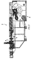
ラム本体は、毎分何度も、周期的に移動する。この動きを実現するために、ボディ製造機はまた、クランクアームを有するクランクアセンブリを含む。クランクアームは、ラムアセンブリに接続され、ラムアセンブリを往復させる。ラム本体は、中空の再絞りスリーブ及びダイパックと軸方向にほぼ揃えられる。このアライメントは重要であって、なぜならば、位置のずれはラムがダイをすり減らす原因となり、その逆もまた同様だからである。図1Aに示されるように、ラム本体のアラインメントは、ツーリングを通ってラム本体をガイドする静圧/動圧ガイド流体ベアリングアセンブリ5、即ち、「ガイドベアリング」によって改善する。ラムアセンブリキャリッジの両側には付加的な静圧/動圧流体ベアリングアセンブリ6があるが、これらのベアリングはラムを「ガイドする」ことはしない。これらの静圧/動圧流体ベアリングアセンブリ6は、チャネルに配置され、ポート7を有する。ポート7は、上面、側面及び下面に配置されて潤滑流体をもたらす。種々の要因、例えば、これに限定されないが、キャリッジの長さが比較的短いことにより、これらの付加的な静圧/動圧流体ベアリングアセンブリ6がラム本体の向き及びアラインメントを制御することが妨げられる。即ち、チャネル内のキャリッジの「ぐらつき(wobble)」量が小さいと、キャリッジ及び静圧/動圧流体ベアリングアセンブリ6がラム本体をガイドすることが妨げられる。 The ram body moves periodically many times every minute. To achieve this movement, the body making machine also includes a crank assembly having a crank arm. The crank arm is connected to the ram assembly and reciprocates the ram assembly. The ram body is substantially aligned axially with the hollow redraw sleeve and die pack. This alignment is important because misalignment causes the ram to wear out the die and vice versa. As shown in FIG. 1A, the alignment of the ram body is improved by a hydrostatic / dynamic pressure guide fluid bearing assembly 5 or “guide bearing” that guides the ram body through the tooling. There are additional hydrostatic / dynamic fluid bearing assemblies 6 on either side of the ram assembly carriage, but these bearings do not "guide" the ram. These hydrostatic / dynamic pressure fluid bearing assemblies 6 are arranged in channels and have ports 7. Ports 7 are disposed on the top, side and bottom surfaces to provide lubricating fluid. Various factors such as, but not limited to, the relatively short carriage length prevents these additional hydrostatic / dynamic pressure fluid bearing assemblies 6 from controlling the ram body orientation and alignment. It is done. That is, a small “wobble” amount of the carriage in the channel prevents the carriage and hydrostatic / dynamic pressure fluid bearing assembly 6 from guiding the ram body.
故に、本明細書で用いられているように、ラム本体ベアリングに関して用いられる場合の「ガイド」は、ラム本体の向き及びアラインメントを制御することを意味する。故に、本明細書で用いられる「ガイドベアリングアセンブリ」は、ラム本体の向き及びアラインメントを制御するように構成されており、それらを制御する。ラムアセンブリのキャリッジの両側にある先行技術の静圧/動圧流体ベアリングアセンブリ6のようなベアリングは、作用が微少であるか、又は単にラム本体の向き及びアラインメントに影響を及ぼすことができるだけであって、本明細書で用いられるような「ガイド」ベアリングアセンブリではない。換言すると、ラム本体がガイドされなければならない点に注目すると、ラム本体がガイドを有していない場合、ラムキャリッジの両側のベアリングアセンブリは、「ガイドベアリングアセンブリ」である。しかしながら、ラム本体がガイドを有している場合には、ラムキャリッジの両側のベアリングアセンブリは、「ガイドベアリングアセンブリ」ではない。 Thus, as used herein, “guide” when used with respect to ram body bearings means controlling the orientation and alignment of the ram body. Thus, as used herein, a “guide bearing assembly” is configured to control and control the orientation and alignment of the ram body. Bearings such as the prior art hydrostatic / hydrodynamic fluid bearing assembly 6 on either side of the ram assembly carriage may have a minor effect or may only affect the orientation and alignment of the ram body. And not a “guide” bearing assembly as used herein. In other words, noting that the ram body must be guided, if the ram body does not have a guide, the bearing assemblies on both sides of the ram carriage are “guide bearing assemblies”. However, if the ram body has a guide, the bearing assemblies on both sides of the ram carriage are not “guide bearing assemblies”.
ガイドアセンブリは、典型的には、再絞りアセンブリの上流のすぐ近く(クランクアームの近く)に配置される。流体ベアリングアセンブリは、通路を規定する本体を含む。ラム本体は、流体ベアリングアセンブリの通路を通って延びる。更に、流体ベアリングアセンブリは、流体ベアリングアアセンブリの本体とラム本体との間に、流体、限定されないが、例えば、油を導入する。流体の量及び圧力を制御することで、中空の再絞りスリーブ及びダイパックとのラム本体のアラインメントを正確に制御することができる。流体ベアリングアセンブリの流体は、シールアセンブリによって収集されて再利用される。 The guide assembly is typically located immediately upstream of the redraw assembly (near the crank arm). The fluid bearing assembly includes a body that defines a passage. The ram body extends through the passage of the fluid bearing assembly. Further, the fluid bearing assembly introduces fluid, but not limited to oil, between the body of the fluid bearing assembly and the ram body. By controlling the amount and pressure of the fluid, the alignment of the ram body with the hollow redraw sleeve and die pack can be accurately controlled. The fluid in the fluid bearing assembly is collected and reused by the seal assembly.
この構成の不利な点は、流体ベアリングアセンブリの流体が、シールアセンブリによって完全には取り除かれないということである。故に、冷却流体が使用される場合、流体ベアリングアセンブリの流体の一部は、ラム本体に残る。更に、流体が混ざり合って、収集された冷却流体は、汚染される。このことはまた、高価な油であり得る流体ベアリングアセンブリの流体が、徐々に失われることを意味する。 A disadvantage of this configuration is that the fluid in the fluid bearing assembly is not completely removed by the seal assembly. Thus, when cooling fluid is used, a portion of the fluid in the fluid bearing assembly remains in the ram body. Furthermore, it intermingled fluid, collected the cooling fluid is contaminated. This also means that fluids in the fluid bearing assembly, which can be expensive oil, are gradually lost.
もう一つの不利な点は、ラム本体が、ダイパックのみならず、シールアセンブリ及び流体ベアリングアセンブリを通って延びるのに充分な長さを有していなければならないことである。一般的な12液量オンス缶の缶ボディでは、一般的な12液量オンス缶用の24インチストロークを使用した場合、ラム本体の長さは約50インチ乃至52インチとなる。ラムの長さはストロークの長さによって異なり、これにより異なるサイズの缶ボディを支持する。例えば、以下は、一般的なラムの長さと、それに関連するストロークとを示した表である。 Another disadvantage is that the ram body must be long enough to extend through the seal and fluid bearing assemblies as well as the die pack. A typical 12 fluid ounce can body can have a ram body length of about 50 inches to 52 inches when using a 24 inch stroke for a typical 12 fluid ounce can. The length of the ram depends on the length of the stroke, thereby supporting different sized can bodies. For example, the following is a table showing typical ram lengths and associated strokes.

これらの何れの長さのラム本体も、通常使用による消耗によって損傷しやすい。 Any of these lengths of ram body are susceptible to damage due to wear from normal use.
上記のように、ラム本体は、缶ボディを形成するときに第1の方向にダイパックを通過し、続いて、缶ボディが形成された後にダイパックを逆行する。ボディ製造機のダイパックは、互いに離間した複数のダイを有し、各ダイは開口を有する。各ダイの開口は、隣接する上流側のダイよりも僅かに小さい。ダイパックにおける後続するダイの開口は、より小さな内径、即ち、より小さな開口を有する。そのため、ラムがダイパックの残りにアルミニウムを通すと、アルミニウムカップは薄くなる。パンチと再絞りダイ間との空間は通常、金属の肉厚を超えた未詳な隙間(1側面につき0.001〜2インチ)であり、最後のしごき加工ダイでは0.004インチ未満である。一般的な12液量オンス缶を作製するのに用いられる典型的なアルミニウムゲージが、今日では実際のところ、0.0108インチである。しかしながら、このように空間を狭くすることは、特に戻り工程において不利である。 As described above, the ram body passes through the die pack in a first direction when forming the can body, and then reverses the die pack after the can body is formed. A die pack of a body manufacturing machine has a plurality of dies spaced apart from each other, and each die has an opening. The opening of each die is slightly smaller than the adjacent upstream die. Subsequent die openings in the die pack have a smaller inner diameter, ie, a smaller opening. Therefore, when the ram passes aluminum through the rest of the die pack, the aluminum cup becomes thinner. The space between the punch and the redraw die is typically an unknown gap (0.001 to 2 inches per side) exceeding the metal thickness, and less than 0.004 inches for the last ironing die. A typical aluminum gauge used to make a typical 12 fluid ounce can is today 0.0108 inches in practice. However, such a narrowing of the space is disadvantageous especially in the return process.
缶の直径、缶の高さ及びマシンモデルに応じて、ストロークの長さが22〜30インチで変化し、且つスループットの頻度が210乃至450ストローク/分(SPM)に及ぶようなこの細長い水平ラム及びパンチには、ラムの垂れ又は撓みがつきものである。最も単純な形態において、ラムは、片持ち梁として一端に固定されており、他端では自由であるように描出される。上側の理論化された梁のタイプは、タングステンカーバイド製パンチの重量によるラムの撓みを示す。下側の理論化された梁のタイプは、自重による、長いスチール製ラムの撓みを示す。既知のボディ製造機における水平ラムの総撓みは、これらの2つの影響の組合せである。 Depending on the can diameter, can height and machine model, this elongated horizontal ram whose stroke length varies from 22 to 30 inches and the throughput frequency ranges from 210 to 450 strokes per minute (SPM) And the punch is accompanied by sagging or bending of the ram. In its simplest form, the ram is depicted as being cantilevered at one end and free at the other end. The upper theorized beam type shows ram deflection due to the weight of the tungsten carbide punch. The lower theorized beam type shows the deflection of a long steel ram due to its own weight. The total deflection of the horizontal ram in known body making machines is a combination of these two effects.
ラム及びパンチアセンブリの典型的な重量は、合計でおよそ50lbfである。撓み(δ)、即ちラムの垂れの最大値は、細長い軽量のスチール製ラム(ρsteel=0.284lb/in3)と、ラムの先端の重いタングステンカーバイド(即ち、WC−ρWC=0.567lb/in3)製パンチの重量(点荷重P又は分布荷重ω)と直線的に比例する。しかしながら、(片持ち梁として概念化された)撓み又はラムの垂れの最大値は、長さ(l)、即ち、細長いスチールラムについてはその4乗の長さ、ラム先端の重いカーバイドパンチについてはその3乗の長さによって左右される。Iは、周知の通り、断面二次モーメント(area moment of inertia)である。従って、ラムを短くできれば、撓み又はラムの垂れがかなり低減され得る。静圧/動圧ラムベアリングを主たるラム自体の外に配置する(outboard)概念は、ラムの長さを短くするのに不可欠である。なぜなら、ラムはもはや、缶ボディ製造プロセスを通してベアリングによって支えられるための付加的な長さを必要としないからである。ラムの垂れは、缶が形成されない戻り工程における問題である。戻り工程においては、パンチ及びラムがツーリングに接触する傾向が強く、これが摩耗及び損傷の原因となる。この大きな一因が、機械の戻り工程におけるパンチとしごきダイ(主に第3のアイロン又は最後のアイロン)と間の接触である。 The typical weight of the ram and punch assembly is approximately 50 lbf in total. The maximum deflection (δ), or ram sagging, is a long and light steel ram (ρ steel = 0.284 lb / in 3 ) and a heavy tungsten carbide at the tip of the ram (ie WC−ρ WC = 0. 567 lb / in 3 ) linearly proportional to the weight of the punch (point load P or distributed load ω). However, the maximum value of deflection or ram sag (conceptualized as a cantilever beam) is the length (l), that is, the length of its fourth power for elongated steel rams, and that for heavy carbide punches at the ram tip. It depends on the length of the cube. As is well known, I is an area moment of inertia. Thus, if the ram can be shortened, deflection or ram droop can be significantly reduced. The concept of outboarding the hydrostatic / dynamic ram bearings outside the main ram itself is essential to reduce the length of the ram. This is because the ram no longer requires an additional length to be supported by the bearing throughout the can body manufacturing process. Lamb sag is a problem in the return process where no can is formed. In the return process, the punch and ram tend to come into contact with the tooling, which causes wear and damage. One major reason for this is the contact between the punch and ironing die (mainly the third or final iron) in the return process of the machine.
更に、上記のように、ラム本体は、静圧/動圧流体ベアリングアセンブリを通過する。静圧/動圧流体ベアリングアセンブリは、缶ボディ製造機のハウジングアセンブリのバルクヘッドに固定される。このことは、ラム本体の片持ち部分の長さが、ボディ製造サイクル中に変化することを意味する。即ち、ラム本体が引き込まれて第1の位置にある場合、ラム本体の片持ち部分の長さは、比較的短い。反対に、ラム本体が延びて第2の位置にある場合、ラム本体の片持ち部分の長さは、比較的長い。ラム本体の片持ち部分の長さの動的性質は、垂れ量が同様に動的に変化することを意味する。このことは、ラムの垂れを補償するシステムまた動的なシステムでなければならないことを意味する。 Further, as described above, the ram body passes through a hydrostatic / dynamic pressure fluid bearing assembly. The hydrostatic / dynamic pressure fluid bearing assembly is secured to the bulkhead of the housing assembly of the can body making machine. This means that the length of the cantilevered portion of the ram body changes during the body manufacturing cycle. That is, when the ram body is retracted and is in the first position, the length of the cantilevered portion of the ram body is relatively short. Conversely, when the ram body extends and is in the second position, the length of the cantilevered portion of the ram body is relatively long. The dynamic nature of the length of the cantilevered portion of the ram body means that the amount of sag changes dynamically as well. This means that the system must compensate for sag drooping or be dynamic.
従って、ラムの垂れの影響を受けにくいラム本体を含むラムアセンブリが求められている。より詳細には、長さが短いラム本体が求められている。即ち、ラム本体の長さが、定められた問題である。 Accordingly, there is a need for a ram assembly that includes a ram body that is less susceptible to ram drooping. More specifically, there is a need for a ram body that is short in length. That is, the length of the ram body is a defined problem.
これらの要請とその他の要請は、本発明の少なくとも1つの実施形態によって満たされる。本発明は、一実施形態において、直径が、例えば、典型的な12流体オンスの缶について、約2.0乃至2.5インチであり、長さが約30.0インチ乃至32.0インチ、又は約31.0インチであるラム本体を有するラムアセンブリを提供する。別の例示的な実施形態においては、ラムシールアセンブリが用いられ、ラム本体の長さは、約33.0インチ乃至約36.0インチ、又は約34.5インチである。この実施形態において、ラム本体の直径は、典型的な12流体オンスの缶について、約1.5乃至約3.5インチ、又は約2.5インチである。 These needs and others are met by at least one embodiment of the present invention. The present invention, in one embodiment, has a diameter of, for example, about 2.0 to 2.5 inches and a length of about 30.0 inches to 32.0 inches for a typical 12 fluid ounce can. Alternatively, a ram assembly having a ram body that is approximately 31.0 inches is provided. In another exemplary embodiment, a ram seal assembly is used and the length of the ram body is from about 33.0 inches to about 36.0 inches, or about 34.5 inches. In this embodiment, the diameter of the ram body is about 1.5 to about 3.5 inches, or about 2.5 inches for a typical 12 fluid ounce can.
別の実施形態において、缶ボディ製造機のラムアセンブリは、アウトボードガイドベアリングアセンブリを含む。アウトボードガイドベアリングアセンブリは、「アウトボード(outboard)」しており、即ち、本明細書で用いられているように、ラム本体から離間している。アウトボードガイドベアリングアセンブリは、キャリッジアセンブリ及びベアリングアセンブリを含む。ベアリングアセンブリは、例示的な実施形態において、キャリッジアセンブリの両側に配置される2つのベアリングを含む。例示的な実施形態において、ベアリングアセンブリは、静圧/動圧ベアリングアセンブリである。アウトボードガイドベアリングアセンブリを使用すると、ラム本体がベアリングアセンブリ及びダイパックを通って延びる必要がないので、ラム本体を短くすることが可能となる。 In another embodiment, the ram assembly of the can body making machine includes an outboard guide bearing assembly. The outboard guide bearing assembly is "outboard", i.e., spaced from the ram body as used herein. The outboard guide bearing assembly includes a carriage assembly and a bearing assembly. The bearing assembly includes two bearings disposed on opposite sides of the carriage assembly in the exemplary embodiment. In the exemplary embodiment, the bearing assembly is a hydrostatic / dynamic pressure bearing assembly. Using an outboard guide bearing assembly allows the ram body to be shortened because the ram body need not extend through the bearing assembly and die pack.
別の実施形態では、缶ボディ製造機のラムアセンブリは、細長い、ほぼ中空のラム本体と引張アセンブリとを含む。ラム本体は、近位端、中央部分及び遠位端を含む。引張アセンブリは、細長い支持部材を含む。引張アセンブリの支持部材は、近位端及び遠位端を含む。引張アセンブリの支持部材は、ラム本体内にほとんど配置され、引張アセンブリの支持部材の近位端は、ラム本体の近位端に結合され、引張アセンブリの支持部材の遠位端は、ラム本体の中央部分又はラム本体の遠位端の一方に結合される。 In another embodiment, a ram assembly of a can body making machine includes an elongated, generally hollow ram body and a tensioning assembly. The ram body includes a proximal end, a central portion and a distal end. The tension assembly includes an elongated support member. The support member of the tension assembly includes a proximal end and a distal end. The tension assembly support member is mostly disposed within the ram body, the proximal end of the tension assembly support member is coupled to the proximal end of the ram body, and the distal end of the tension assembly support member is coupled to the ram body. Coupled to one of the central portion or the distal end of the ram body.
好ましい実施形態についての以下の説明を、添付の図面と併せて読むことによって、本発明の充分な理解を得ることができる。 A full understanding of the invention can be obtained by reading the following description of the preferred embodiments in conjunction with the accompanying drawings, in which:
例えば「時計方向」、「反時計方向」、「左」、「右」、「上」、「底」、「上方」、「下方」、及びこれらの派生語など、本明細書において使用される方向に関する表現は、図面に示されている要素の向きに関連しており、特許請求の範囲に明示的に記載されない限り、特許請求の範囲を限定するものではない。 For example, “clockwise”, “counterclockwise”, “left”, “right”, “top”, “bottom”, “upward”, “downward”, and derivatives thereof are used herein. Reference to orientation relates to the orientation of elements shown in the drawings and does not limit the scope of the claims, unless explicitly stated in the claims.
本明細書で用いられているように、「1つ」及び「その」のような単数形は、複数を含まないことを文脈が明らかに定めていない限り、複数への言及を含む。 As used herein, the singular forms “a” and “the” include plural references unless the context clearly dictates that the plural is not included.
本明細書で用いられているように、2つ以上の部品又は構成要素が「結合される」という記述は、リンクが生じる限りにおいて、直接的に、又は、間接的に、つまり、1又は複数の中間部又は構成要素を介して、部品が結合される又は一緒に動作することを意味している。本明細書で用いられる「直接的に結合される」は、2つの要素が互いに直接的に接触していることを意味する。本明細書で用いられる「固定して結合される」又は「固定される」は、2つの構成要素が1つとして移動するように結合されていると同時に、互いに対して一定の向きを維持していることを意味する。従って、2つの要素が結合されると、これらの要素の全ての部分が結合される。しかしながら、第1のホイールに結合されている心棒の第1の端部のような、第2の要素に結合されている第1の要素の特定の部分の記載は、第1の要素の特定の部分は、他の部分よりも第2の要素の近くに配置されることを意味している。更に、別の物体に載置されている物体が、重力のみによってその場に保持されている場合、上側の物体がその場に実質的に維持されていない限り、下側の物体に「結合」されていない。即ち、例えば、テーブル上の本はテーブルに結合されていないが、テーブルに接着された本はテーブルに結合されている。 As used herein, a statement that two or more parts or components are “coupled” is used directly or indirectly, ie, one or more, as long as the link occurs. It is meant that the parts are joined or operate together via the middle part or component of the. As used herein, “directly coupled” means that two elements are in direct contact with each other. As used herein, “fixedly coupled” or “fixed” means that two components are coupled to move as one while maintaining a constant orientation relative to each other. Means that Thus, when two elements are combined, all parts of these elements are combined. However, a description of a particular portion of the first element that is coupled to the second element, such as the first end of the mandrel that is coupled to the first wheel, A part means that it is located closer to the second element than the other part. Furthermore, if an object placed on another object is held in place only by gravity, it will be “coupled” to the lower object unless the upper object is substantially maintained in place. It has not been. That is, for example, the book on the table is not coupled to the table, but the book bonded to the table is coupled to the table.
本明細書で用いられているように、2つ以上の部品又は構成要素が互いに「係合する」という記述は、直接的に、或いは1又は複数の中間要素又は構成要素を介して、要素が互いに対して力を及ぼし、又は付勢することを意味する。 As used herein, a statement that two or more parts or components “engage” each other means that the element is directly or via one or more intermediate elements or components. Means exerting or energizing each other.
本明細書で用いられているように、用語「一体(unitary)」は、構成要素が単一の片又はユニットとして作られていることを意味する。即ち、別々に作られてからユニットとして互いに結合されている片を含む構成要素は、「一体」な構成要素又は物体ではない。 As used herein, the term “unitary” means that the components are made as a single piece or unit. That is, a component that includes pieces that are made separately and then joined together as a unit is not an “integral” component or object.
本明細書で用いられているように、用語「幾つか」は、1又は1よりも大きい整数(即ち、複数)を意味する。 As used herein, the term “some” means one or an integer greater than one (ie, a plurality).
本明細書で用いられているように、「カップリングアセンブリ」は、2つ以上のカップリング又はカップリング構成要素を含む。カップリング又はカップリングアセンブリの複数の構成要素は一般に、同じ要素又は他の構成要素の一部ではない。従って、「カップリングアセンブリ」の複数の構成要素は、以下の説明において同時に記載されないことがある。 As used herein, a “coupling assembly” includes two or more couplings or coupling components. Multiple components of a coupling or coupling assembly are generally not part of the same or other components. Accordingly, multiple components of the “coupling assembly” may not be described simultaneously in the following description.
本明細書で用いられているように、「カップリング」又は「カップリング構成要素」は、カップリングアセンブリの1又は複数の構成要素である。即ち、カップリングアセンブリは、一緒に結合されるように構成された少なくとも2つの構成要素を含む。カップリングアセンブリの構成要素は、互いに適合性すると理解される。例えば、カップリングアセンブリにおいて、一方のカップリング構成要素がスナップソケットであるならば、他方のカップリング構成要素はスナッププラグである。又は、一方のカップリング構成要素がボルトであるならば、他方のカップリング構成要素はナットである。 As used herein, a “coupling” or “coupling component” is one or more components of a coupling assembly. That is, the coupling assembly includes at least two components configured to be coupled together. The components of the coupling assembly are understood to be compatible with each other. For example, in a coupling assembly, if one coupling component is a snap socket, the other coupling component is a snap plug. Or, if one coupling component is a bolt, the other coupling component is a nut.
本明細書で用いられているように、「関連する」は、要素が、同じアセンブリの一部である、及び/又は協働すること、或いは、何らかの形で互いに/共に作動することを意味する。例えば、自動車は、4つのタイヤと4つのハブキャップを有する。全ての要素が自動車の一部として結合される一方で、各ハブキャップが特定のタイヤと「関連する」と理解される。 As used herein, “related” means that the elements are part of the same assembly and / or cooperate or operate in some way / with each other. . For example, an automobile has four tires and four hub caps. While all elements are combined as part of the vehicle, each hub cap is understood to be “associated” with a particular tire.
本明細書で用いられているように、「対応する」は、2つの構造要素が、互いに類似する大きさ及び形状にされており、最小量の摩擦で互いに結合できることを表す。故に、部材に「対応する」開口は、部材が開口を最小量の摩擦で通過できるように、当該部材よりも僅かに大きくされている。この定義は、2つの構成要素が互いに「ぴったりと(snugly)」適合している、又は「ぴったりと対応する」と言われる場合には変更される。このような状況では、構成要素の大きさの差異は更に小さく、これによって摩擦量は増大する。開口を規定する要素及び/又は開口に挿入される構成要素が、変形又は圧縮可能な材料で作られている場合には、開口は、開口に挿入される構成要素よりも僅かに小さくてよい。この定義は更に、2つの構成要素が「ほとんど対応する」と言われる場合に、変更される。「ほとんど対応する」は、開口の大きさが、その中に挿入される要素の大きさに非常に近いことを意味する。即ち、ぴったり適合する場合のように、顕著な摩擦を生じさせるほどは近くないが、「対応する適合」、即ち「僅かに大きな」適合よりも接触及び摩擦が大きい。更に、本明細書で用いられる「疎に(loosely)対応する」は、スロット又は開口が、その中に配置される要素よりも大きくされていることを意味する。このことは、スロット又は開口の大きさの増大が意図的であり、製作公差よりも大きいことを意味する。更に、2つ以上の要素によって形成されている表面に関して、「対応する」形状とは、表面形状、例えば曲率が類似することを意味する。 As used herein, “corresponding” indicates that two structural elements are sized and shaped similar to each other and can be coupled to each other with a minimum amount of friction. Thus, the opening "corresponding" to the member is slightly larger than the member so that the member can pass through the opening with the least amount of friction. This definition is changed when two components are said to “snugly” fit or “just correspond” to each other. In such a situation, the difference in component sizes is even smaller, which increases the amount of friction. If the element defining the opening and / or the component inserted into the opening is made of a deformable or compressible material, the opening may be slightly smaller than the component inserted into the opening. This definition is further modified when two components are said to be “mostly corresponding”. “Almost corresponding” means that the size of the opening is very close to the size of the element inserted therein. That is, it is not close enough to cause significant friction, as in the case of a close fit, but has more contact and friction than a “corresponding fit”, ie “slightly larger” fit. Further, as used herein, “loosely correspond” means that the slot or opening is made larger than the element disposed therein. This means that an increase in the size of the slot or opening is intentional and is greater than the manufacturing tolerance. Furthermore, with respect to a surface formed by two or more elements, a “corresponding” shape means that the surface shape, eg, curvature, is similar.
本明細書で用いられているように、「[動詞]するように構成される」は、特定の要素又はアセンブリが、特定の動詞を実行するように形作られ、大きさを決められ、配置され、結合され、及び/又は構成されている構造を有することを意味する。例えば、「移動するように構成された」部材は、別の要素に移動可能に結合されており、当該部材を動かす要素を含んでいる。或いは、部材は、別のやり方で、他の要素若しくはアセンブリに応答して移動するように構成されている。 As used herein, “configured to [verb]” means that a particular element or assembly is shaped, sized and arranged to perform a particular verb. , And / or having a structured structure. For example, a member “configured to move” is movably coupled to another element and includes an element that moves the member. Alternatively, the member is otherwise configured to move in response to other elements or assemblies.
本明細書で用いられているように、「片持ち梁(cantilever)」は、1又は複数の点で支持される突出した梁又は他の水平部材を意味する。 As used herein, “cantilever” means a protruding beam or other horizontal member that is supported at one or more points.
本明細書で用いられているように、「引張部材」は、張力を受けると長さが最大になる、さもなければ、かなりの可撓性がある構造体であり、例えば鎖やケーブルが例として挙げられるが、これらに限られない。 As used herein, a “tensile member” is a structure that has a maximum length when subjected to tension, or is otherwise quite flexible, such as a chain or cable. However, it is not limited to these.
図2乃至図7に示されるように、缶ボディ製造機10は、カップ2(図2)を缶ボディ3(図2)に変換するように構成される。以下に記載されるように、カップ2、ラム本体50、ダイパック16を通る通路、及び他の要素は、略円形の断面を有すると仮定される。しかしながら、カップ2及び結果として得られる缶ボディ3と、カップ2又は缶ボディ3と相互作用する要素とは、略円形以外の形状を有していてよいことが理解される。カップ2は底部4を有しており、付随する側壁5は、実質的に包囲された空間(図示せず)を規定する。カップの底部4の端は開いている。
As shown in FIGS. 2-7, the can
缶ボディ製造機10は、ハウジングアセンブリ11、往復ラムアセンブリ12、駆動機構14、ダイパック16、再絞りアセンブリ18、及びカップフィーダ20を含む。ここで特定された各要素は、ハウジングアセンブリ11に結合される。例示的な実施形態において、駆動機構14は、往復運動クランクアーム32を含むクランクアセンブリ30を含む。周知のように、各サイクルにおいて、カップフィーダ20は、ダイパック16の前方にカップ2を配置し、開放端は、ラムアセンブリ12に向く。カップ2がダイパック16の前方にある場合にて、再絞りスリーブ40は、カップ2を再絞りダイ42に対して付勢する。周知のように、駆動機構14は、例えば幾つかの二次的クランクアーム36(図5)を介して再絞りスリーブ40を駆動し、再絞りスリーブ40が進んだ直後にラムアセンブリ12が進むようにタイミング設定される。例示的な実施形態では、ハウジングアセンブリ11は、ラム本体50用のシールアセンブリを備えていない。即ち、ラムは潤滑されないので、ラム本体50は、潤滑剤を収集するように構成されたシールアセンブリを通って延びない。
The can
一般に、ラムアセンブリ12は、細長い略円形のラム本体50を含み、ラム本体50は、近位端52、遠位端54、及び長手方向軸56を有する。ラム本体の遠位端54はパンチ58を含む。ラム本体の近位端52は、駆動機構14と接続される。駆動機構14はラム本体50に往復運動をもたらし、ラム本体50はその長手方向軸56に沿って前後に移動する。即ち、ラム本体50は、第1の引き込み位置と、第2の前進位置との間を往復運動するように構成されている。第1の引き込み位置において、ラム本体50は、ダイパック16から離間している。第2の延びた位置において、ラム本体50は、ダイパック16を通って延びている。従って、往復ラムアセンブリ12は、再絞りスリーブ40を通過し、カップ2を係合して前方へ(図では左へ)向かって進む。カップ2は、再絞りダイ42と、ダイパック16内にある幾つかのしごきダイ(図示せず)とを通って移動する。カップ2は、ダイパック16内で缶ボディ3に変換されてから、そこから取り出される。本明細書で用いられるように、「サイクル」は、ラムアセンブリ12の第1の引き込み位置から始まるラムアセンブリ12のサイクルを意味することが理解される。
In general, the
故に、缶ボディ3を運ぶパンチ58がダイパック16を通過すると、缶ボディ3は変形する。より具体的には、缶ボディ3は細長くなり、側壁5はより薄くなる。形成工程の最後に、周知の方法によって、缶の底部4にドームが形成されてよい。更に、戻り工程の開始時に、缶ボディ3がパンチ58から取り出されるが、これには如何なる周知の方法又は装置が用いられてもよく、例えば、ストリッパー装置又は缶ボディ3の内側に圧縮されたガスを供給する方法が挙げられるが、これらに限られない。次の形成工程の開始時に、新たなカップ2がパンチ58の端部を覆って配置される。
Therefore, when the
図5乃至図9に示されているように、例示的な実施形態において、ラムアセンブリ12はまた、アウトボードガイドベアリングアセンブリ60を含む。第1の例示的な実施形態では、アウトボードガイドベアリングアセンブリ60は、キャリッジアセンブリ62と幾つかの細長いジャーナル64とを含む。図示しないある実施形態においては、単一のジャーナル64が、ラム本体50の鉛直方向下側に配置されて、ラム本体50と揃えられており、即ち、ラム本体50と平行であるが、離間している。図示された実施形態では、2つのジャーナル64、即ち、第1のジャーナル66及び第2のジャーナル68が存在しており、それらは、ラム本体50と略水平方向に揃えられており、即ち、ラム本体50と同一の略水平面内にある。例示的な実施形態においては、第1のジャーナル66及び第2のジャーナル68は、ラムアセンブリ12のストローク長さよりも僅かに長く、ボディ製造機のハウジングアセンブリ11に結合される。
As shown in FIGS. 5-9, in the exemplary embodiment, the
キャリッジアセンブリ62は、2つのジャーナル66、68を有する実施形態では、ラムカップリング72、クランクカップリング74を含む略矩形の本体70を含んでおり、本体70は、幾つかのジャーナル通路80を規定する。例示的な実施形態において、ラムカップリング72は、略水平方向にラム本体50を支持するように構成される。クランクカップリング74は、例示的な実施形態において、クランクアーム32の略円形の開口(図示せず)を通って延びるように構成された略円形のベアリング76である。
The
例示的な実施形態において、幾つかのジャーナル通路80は、ほぼ揃えられたジャーナル通路の第1の対82と、ほぼ揃えられたジャーナル通路の第2の対84とを含む。ジャーナル通路の各対82、84におけるジャーナル通路80は、離間している。例示的な実施形態において、ジャーナル通路の各対82、84におけるジャーナル通路80は、約8.0乃至12.0インチ、又は約10.25インチ長手方向に離間している。第1のジャーナル66は、ほぼ揃えられたジャーナル通路の第1の対82を通って延び、第2のジャーナル68は、ほぼ揃えられたジャーナル通路の第2の対84を通って延びる。例示的な実施形態において、ジャーナル通路80は、キャリッジアセンブリの矩形の本体70の各隅部に配置される。
In the exemplary embodiment, the number of
ジャーナル通路の各対82、84におけるジャーナル通路80はそれぞれ、ベアリングアセンブリ90を含む。ある実施形態において、ベアリングアセンブリ90は、炭素繊維ベアリング(図示せず)を含んでいる。このような炭素繊維ベアリングは、潤滑剤を必要とせず、これに限定されないが、ボールベアリングのような移動要素を含まない。故に、ある実施形態において、ベアリングアセンブリ90は、「静的ベアリングアセンブリ」である。即ち、本明細書で用いられる「静的ベアリングアセンブリ」は、潤滑剤を必要とせず、動く要素を含まないベアリングアセンブリである。
Each
このような構成において、キャリッジアセンブリの本体70は、略平面内を移動し、第1の引き込み位置と、第2の前進位置との間を往復運動するように構成される。キャリッジアセンブリの本体70が第1の位置にあると、ラム本体50はその第1の位置にあり、キャリッジアセンブリの本体70が第2の位置にあると、ラム本体50はその第2の位置にあることは理解される。故に、キャリッジアセンブリの本体70は、ラム本体の長手方向軸56とほぼ揃えられる運動の軸78を有する。即ち、キャリッジアセンブリの本体の運動の軸78は、ラム本体の長手方向軸56と平行であり且つ長手方向軸56から離間してよく、或いは、ほぼ長手方向軸56上に配置されてもよい。
In such a configuration, the
別の実施形態では、図8及び図9に最も良く示されているように、各ベアリングアセンブリ90は、静圧/動圧ベアリングアセンブリ100である。本明細書で用いられているように、「静圧/動圧ベアリングアセンブリ」は、静圧ベアリングアセンブリ、動圧ベアリングアセンブリ、又はこれらの組合せの何れかである。周知のように、静圧/動圧ベアリングアセンブリ100は、ハウジング102及びベアリング104を含む。ベアリング104は、ハウジング102内に配置される。ベアリング104は、通路80を規定し、先に説明したように、これを通ってジャーナル64が延びる。静圧/動圧ベアリングアセンブリ100、即ちアウトボードガイドベアリングアセンブリ60は更に、潤滑剤サンプ106、ポンプアセンブリ108、及び複数の導管110を含んでおり、全て模式的に示されている。静圧/動圧ベアリングアセンブリ導管110は、静圧/動圧ベアリングアセンブリのハウジング102及びベアリング104を通って延びる導管を含む。周知のように、潤滑剤、限定されないが、例えば油が導管110を通過し、ベアリング表面とジャーナル64との間に配置される。或いは、ベアリング104の直動回転が、ベアリング104の内面に流体を引き寄せて、ジャーナル64の下又は周りに潤滑ウェッジ(lubricating wedge)又は流体リフト(fluid lift)を形成する。
In another embodiment, each bearing
静圧/動圧ベアリングアセンブリ100は、例示的な実施形態では、ラム本体50から離れているので、冷却液と静圧/動圧ベアリングアセンブリ潤滑剤との相互汚染が大幅に少なくなる。故に、例示的な実施形態では、アウトボードガイドベアリングアセンブリ60は、潤滑剤を収集して、潤滑剤を潤滑剤サンプ106又はフィルタアセンブリに戻すようなシールアセンブリを含んでいない。それどころか、ハウジングアセンブリ11の一部、即ちアウトボードガイドベアリングアセンブリ60の下側の部分は、ほぼ中空であり、サンプ106として作用する囲まれた空間を規定する。このような構成では、ジャーナル64からの潤滑剤はサンプ106に入る。更に、ラム本体50とは異なり、ジャーナル64は、冷却流体が必要とされる温度にまで加熱されない。故に、ジャーナル64及び/又は静圧/動圧ベアリングアセンブリ100と関連した冷却アセンブリは存在しない。ジャーナル64及び/又は静圧/動圧ベアリングアセンブリ100と関連したフィルタアセンブリも存在しないが、これは、潤滑剤を冷却流体から分離する必要がないからである。
Since the hydrostatic /
例示的な実施形態では、組み立てられると、第1のジャーナル66及び第2のジャーナル68は、先に述べたように、水平方向に、即ち同一の略水平面内に揃えられる。更に、第1のジャーナル66及び第2のジャーナル68は、ジャーナル通路の2つの対82、84を通って延びる。故に、キャリッジアセンブリの本体70は、略水平面内を移動するように構成される。更に、ラム本体50はまた、例示的な実施形態において、キャリッジアセンブリのラムカップリング72に結合され、直接的に結合され、又は固定される。より詳細には、ラム本体の近位端52は、キャリッジアセンブリのラムカップリング72に結合され、直接的に結合され、又は固定される。更に、例示的な実施形態において、ラム本体50は、第1のジャーナル66及び第2のジャーナル68によって規定される水平面内に配置される。ラム本体50及びキャリッジアセンブリの本体70は、ラム本体の長手方向軸56とほぼ揃えられた方向に移動し、より詳細には往復運動する。故に、キャリッジアセンブリのラムカップリング72は、ほぼ移動平面内にラム本体50を支持するように構成される。
In the exemplary embodiment, when assembled, the
アウトボードガイドベアリングアセンブリ60を利用することで、先に述べたように、缶ボディ製造機10は、シールアセンブリがラム本体50の周りに配置されずとも動作できる。更に、ラム本体50は、静圧/動圧ベアリングアセンブリ100を通過しない。故に、これらの要素/アセンブリ及びダイパック16を通過するのに充分な長さがなければならない既知のラム本体とは異なり、例示的な実施形態のラム本体50は、ダイパック16を通過するのに充分な長さを必要とするだけである。ラム本体50の長さのこの縮小によって、ラムの垂れ量が低減し、これによって、ラム本体50及びダイパック16の摩滅が軽減する。例示的な実施形態では、ラム本体50の長さは、約30.0インチ乃至32.0インチであり、別の実施形態においては、長さは約31.0インチである。即ち、大きさの変化により、既知の技術において知られている欠点が改善する。
By utilizing the outboard
既知のラム本体50には、幾つかのサイズが存在する。先に特定した寸法は、ある例示的な実施形態、例えば、標準的な12液量オンスの缶用に大きさが決められたラム本体50と関連している。先行技術では、そのようなラム本体の長さは、24インチのストロークを用いる場合、約50インチ乃至52インチであった。従って、開示された発明は、ラム本体の長さを、約40%プラスマイナス約1インチ縮小可能とすることが理解される。その他の知られているラム本体の長さとして、45.387インチ、50.0インチ、51.0インチ及び57.0インチがあり、それらの長さにプラスマイナス約1インチしたものを含む。故に、開示された発明はまた、全てプラスマイナス約1インチで、長さが約27.0インチ、30.0インチ、及び34.2インチのラム本体(図示せず)を提供する。或いは、大まかに述べると、縮小されたラム本体50の長さは約26.0インチ乃至36.0インチであり、それらの全ては、既知のラム本体の長さよりも短い。即ち、本明細書で用いられる「縮小された長さのラム本体」の長さは、約26.0インチ乃至36.0インチである。
There are several sizes of known
別の例示的な実施形態では、図11乃至図13に示されているように、アウトボードガイドベアリングアセンブリ160は、キャリッジアセンブリ162を含んでおり、キャリッジアセンブリ162は、ラムカップリング172、クランクカップリング174及び幾つかのガイドベアリングアセンブリ180を有する本体170を含む。前述のように、キャリッジアセンブリのガイドベアリングアセンブリ180は、ラム本体50から離間している。即ち、前述のように、キャリッジアセンブリの本体170は、例示的な実施形態において、略矩形であり、そして、前側軸面171と、第1の側面173及び第2の側面175とを含む。ラムカップリング172は、キャリッジアセンブリの本体の前側軸面171、即ち運動の軸が通過する前面に配置される。ラムカップリング172は、略水平方向にラム本体50を支持するように構成される。前述のように、キャリッジアセンブリの本体170は、略平面内を移動し、第1の引き込み位置と、第2の前進位置との間を往復運動するように構成される。
In another exemplary embodiment, as shown in FIGS. 11-13, the outboard
キャリッジアセンブリのガイドベアリングアセンブリ180は、例示的な実施形態において、キャリッジアセンブリの2つのガイドベアリングアセンブリ180、つまり、キャリッジアセンブリの第1のガイドベアリングアセンブリ180Aとキャリッジアセンブリの第2のガイドベアリングアセンブリ180Bとを含む。例示的な実施形態において、キャリッジアセンブリの第1のガイドベアリングアセンブリ180Aは、キャリッジアセンブリの本体の第1の側面173に配置されて結合され、キャリッジアセンブリの第2のガイドベアリングアセンブリ180Bは、キャリッジアセンブリの本体の第2の側面175に配置されて結合される。キャリッジアセンブリの第1のガイドベアリングアセンブリ180A及び第2のガイドベアリングアセンブリ180Bの要素はまた、以下に記載されるように、ボディ製造機のハウジングアセンブリ11に結合されることは更に理解される。なお、ラム本体50は、キャリッジアセンブリの本体の前側軸面171に結合され、キャリッジアセンブリの第1のガイドベアリングアセンブリ180A及び第2のガイドベアリングアセンブリ180Bは、キャリッジアセンブリの本体の第1の側面173及び第2の側面175に結合されており、キャリッジアセンブリのガイドベアリングアセンブリ180A、180Bは、ラム本体50から離れていることに留意のこと。
In the exemplary embodiment, the
キャリッジアセンブリの第1のガイドベアリングアセンブリ180A及び第2のガイドベアリングアセンブリ180Bは、ほとんど類似しているので、1つのみを記載することとする。しかしながら、キャリッジアセンブリの各ガイドベアリングアセンブリ180A、180Bは、以後に記載される要素を含んでおり、キャリッジアセンブリの第1のガイドベアリングアセンブリ180Aと関連したそれら要素は、参照文字「A」によって、キャリッジアセンブリの第2のガイドベアリングアセンブリ180Bと関連した要素は、参照文字「B」によって特定されるが、たとえ各要素についての最初の記述にその表示が与えられていなかったとしても、それらの要素が含まれると理解されるべきである。
Since the first
例示的な実施形態において、キャリッジアセンブリのガイドベアリングアセンブリ180は、第1の構成要素182及び第2の構成要素184を含む。キャリッジアセンブリのガイドベアリングアセンブリの第1の構成要素182は、サドル186であり、キャリッジアセンブリのガイドベアリングアセンブリの第2の構成要素184は、ジャーナルチャネル188である。即ち、本明細書で用いられるジャーナルチャネル188は、移動の経路を規定するチャネルであり、先に記載されるジャーナル66、68と類似する。更に、本明細書で用いられているように、「サドル」は、関連するチャネル188とほぼ一致する大きさにされた構造体である。即ち、サドルの断面形状は、チャネルと類似するが、僅かに小さく、長手方向の寸法が縮小されている。この機器構成において、サドル186はチャネル188を通って移動するように構成される。
In the exemplary embodiment,
例示的な実施形態において、ジャーナルチャネル188は、幾つかの略平坦な表面で形成されて、略正方形でC字状のチャネルが形成される。即ち、チャネル188は略矩形の断面を有する。従って、対応するサドル186は同様に、略矩形の断面を有する。更に、図*に示されるように、例示的な実施形態において、サドル186は略平行六面体の構造体である。図示されていない別の実施形態においては、チャネル188及びサドル186は、台形の断面形状を有する。
In the exemplary embodiment,
更に、ある例示的な実施形態では、キャリッジアセンブリのガイドベアリングアセンブリ180は、静圧/動圧ベアリングアセンブリである。この実施形態では、ベアリングアセンブリの第1の構成要素182は、潤滑剤サンプ106に結合されて、潤滑剤サンプ106と流体連通するように構成される。即ち、サドル186は、潤滑剤サンプ106に結合されて、潤滑剤サンプ106と流体連通する幾つかの流体ポート190を含む。前述のように、幾つかの導管110により、潤滑剤の流体連通が実現され、ポンプアセンブリ108によって、サンプ106から流体ポート190を通って潤滑剤をポンプで送ることができる。幾つかの導管110は、例示的な実施形態において、キャリッジアセンブリの本体170を通過する。この構成では、潤滑剤の層が、キャリッジアセンブリのガイドベアリングアセンブリの第1の構成要素182とキャリッジアセンブリのガイドベアリングアセンブリの第2の構成要素184との間に配置される。
Further, in an exemplary embodiment,
例示的な実施形態では、キャリッジアセンブリのガイドベアリングアセンブリの第2の構成要素184は、ジブ(gib)アセンブリ192を含む。ジブアセンブリ192は、幾つかの、典型的には2つの略平行な平らな部材(図示せず)を含んでおり、これらは、離間した調整可能なカップリング構成要素、限定されないが、例えばねじ棒(図示せず)によって結合される。平らな部材の相対的な間隔及び角度は、調整可能なカップリング構成要素を作動させることによって調整されてよい。例えば、ジャーナルチャネル188が、3つの略平らな表面を有する略正方形でC字状のチャネルであれば、各表面がそれぞれジブアセンブリ192によって形成されてよい。即ち、各ジブアセンブリ192の平らな部材の1つが、正方形でC字状のチャネルの平らな各表面を形成する。この構成では、特徴、例えばチャネル表面又はジャーナルチャネル188の断面積のアラインメントが調整できる。
In the exemplary embodiment, the
この実施形態では、ハウジングアセンブリ11は、ラム本体50のためのシールアセンブリ196を含んでいてよく、図では含んでいる。即ち、シールアセンブリ196は、周知のように、2つのカップシール(図示せず)を含んでいる。即ち、一方のカップシールは、ラム本体が第2の位置から第1の位置に移動すると、冷却剤をラム本体50から除去するように構成され、他方のカップシールは、ラム本体50が第1の位置から第2の位置に移動するにつれ、潤滑剤をラム本体50から除去するように構成されている。なお、シールアセンブリ196は、ベアリングアセンブリではなく、ラム本体50を支持しないので、以下に説明されるように、ラム本体50の「片持ち長さ」を変えないことに留意のこと。
In this embodiment, the housing assembly 11 may include a
この実施形態では、ベアリングアセンブリを通過するのに充分な長さがなければならない既知のラム本体とは異なり、この例示的な実施形態のラム本体50は、シールアセンブリ196及びダイパック16を通過するのに充分な長さを必要とするだけである。ラム本体50の長さのこの縮小により、ラムの垂れの量が低減して、これによってラム本体50及びダイパック16の摩滅が軽減する。例示的な実施形態において、ラム本体50は、約33.0インチ乃至約36.0インチ、又は約34.5インチの長さがある。即ち、大きさの変化により、既知の技術の欠点が改善する。
In this embodiment, unlike the known ram body, which must be long enough to pass through the bearing assembly, the
アウトボードガイドベアリングアセンブリ60、160の何れかの実施形態を用いて、ラム本体の近位端52は、キャリッジアセンブリのラムカップリング72に結合され、直接的に結合され、又は固定されて、ラム本体50はそこから延びる。ラム本体50は片持ち部材120、220である(図8及び図13)。図3に示された再絞りスリーブ40の右側にあるアセンブリ、限定されないが、例えば、エアブレード44及び機械式ストリッパ46は、ラム本体50を支持しないことに留意のこと。
Using either embodiment of the outboard
更に、片持ち部材120は、「片持ち長さ」を有し、これは、支持されていない一端に最も近い支持物を越えた片持ち部材の長さである。上述のように、ラム本体50がベアリングアセンブリ60を通って移動する先行技術においては、先行技術のラム本体の片持ち長さは、動的な片持ち長さを有していた。即ち、片持ち長さは、ベアリングアセンブリ60を通って延びるラム本体50の長さによって決まっていた。例示的な実施形態のラム本体50は、ベアリングアセンブリ60を通って延びないので、片持ち部材120の片持ち長さは、キャリッジアセンブリ62の往復運動の間も一定に保たれる。
Further, the
別の例示的な実施形態では、図10、図10A及び図10Bに示されているが、ラムアセンブリ12は、細長い、略円形の、ほぼ中空のラム本体50Aを含む。前述のように、ラム本体50Aは、近位端52、遠位端54及び長手方向軸56、並びに中間部分59を含む。例示的な実施形態において、そしてラム本体の中間部分59にて、中空のラム本体50Aの内面は、内向きに延びるフランジ130を含む。この例示的な実施形態では、ラム本体のフランジ130は、ラム本体の遠位端54とラム本体の中間部分59との間の境界となる。
In another exemplary embodiment, shown in FIGS. 10, 10A, and 10B, the
パンチ58は、内向きに延びるフランジ130を越えてラム本体の遠位端54に配置される。即ち、ラム本体の遠位端54の半径は、ラム本体の近位端52及びラム本体の中間部分59に対して減少している。パンチ58は略円筒状であり、中空体57を含む。パンチ本体57の外径は、ラム本体の中間部分59及び近位端52の外径とほぼ同じである。パンチ58は、ラム本体の遠位端54を超えて配置され、且つこれに結合される。この構成において、パンチ58とラム本体の中間部分59との間の外側の移行部は、実質的に滑らかである。この例示的な実施形態では、ラムアセンブリ12はまた、引張アセンブリ140を含む。
The
引張アセンブリ140は、ラム本体50Aに張力を与えることによって、ラムの垂れを低減するように構成される。例示的な実施形態において、引張アセンブリ140は、細長い支持部材142、近位カップリングアセンブリ144、及び遠位カップリングアセンブリ146を含む。支持部材142は、近位端150、遠位端152及び長手方向軸154を含む。支持部材142は、例示的な実施形態において、剛性部材又は引張部材の1つである。支持部材142は、ラム本体50A内にほぼ配置される。
The
引張アセンブリの近位カップリングアセンブリ144は、ラム本体の近位端52に配置される。引張アセンブリの近位カップリングアセンブリ144は、例示的な実施形態では、調整可能なカップリングアセンブリ148である。即ち、例示的な実施形態において、支持部材の近位端150と引張アセンブリの近位カップリングアセンブリ144とは、ねじ結合されており、例えば、それぞれは、ねじ棒143と係留ナット145である。図示されているように、支持部材の近位端150は、ラム本体の近位端52内で軸方向の通路149を通って延びる。図示したように、ラム本体の近位端の軸方向の通路149は、内向きに延びるフランジを規定するカラー147に配置される。
The
引張アセンブリの遠位カップリングアセンブリ146は、ラム本体の中間部分59又はラム本体の遠位端54の一方に配置される。例示的な実施形態では、引張アセンブリの遠位カップリングアセンブリ146は、ラム本体のフランジ130に配置される。例示的な実施形態では、引張アセンブリの遠位カップリングアセンブリ146は、マウント260及びマウントカップリングアセンブリ262を含む。即ち、マウントカップリングアセンブリ262は、後述のカップリング構成要素を含んでおり、これはマウント260をラム本体50Aに結合する。引張アセンブリの遠位カップリングアセンブリのマウント260は、本体264を含んでおり、本体264は、軸方向の第1のカップリングアセンブリ266と径方向の第2のカップリングアセンブリ268を規定する。さもなければ、引張アセンブリの遠位カップリングアセンブリのマウント本体264は、ラム本体フランジ130にてラム本体50A内に適合する大きさと形状にされる。引張アセンブリの遠位カップリングアセンブリのマウント本体の第1のカップリングアセンブリ266は、例示的な実施形態において、ねじ付きキャビティ270を含む。別の実施形態では、キャビティ270は、径方向のピンと、その通路(図示せず)とを含む。引張アセンブリの遠位カップリングアセンブリのマウント本体の第1のカップリング構成要素のキャビティ270は、支持部材の遠位端152に対応する。故に、支持部材の遠位端152が、引張アセンブリの遠位カップリングアセンブリのマウント本体の第1のカップリング構成要素のキャビティ270内に螺合して配置されることによって、支持部材142は、引張アセンブリの遠位カップリングアセンブリのマウント本体264に結合される。
The
引張アセンブリの遠位カップリングアセンブリのマウント本体264は、引張アセンブリの遠位カップリングアセンブリのマウント本体の第2のカップリングアセンブリ268によって、ラム本体50Aに結合される。例示的な実施形態において、引張アセンブリの遠位カップリングアセンブリのマウント本体の第2のカップリングアセンブリ268は、ねじ穴290を含んでおり、これは、略径方向に、引張アセンブリの遠位カップリングアセンブリのマウント本体264内に延びている。引張アセンブリの遠位カップリングアセンブリのマウント本体の第2のカップリングアセンブリ268はまた、ファスナー292と、フランジ130にてラム本体の中間部分59を通る径方向の通路294とを含む。引張アセンブリの遠位カップリングアセンブリのマウント本体264は、フランジ130にてラム本体50A内に配置される。引張アセンブリの遠位カップリングアセンブリのマウント本体の第2のカップリング構成要素のファスナー292は、引張アセンブリの遠位カップリングアセンブリのマウント本体の第2のカップリング構成要素の径方向の通路294を通過し、引張アセンブリの遠位カップリングアセンブリのマウント本体の第2のカップリング構成要素のねじ穴290に螺入されることによって、引張アセンブリの遠位カップリングアセンブリのマウント260が、ラム本体50Aに結合されて固定される。
The tension assembly distal coupling
支持部材142は、引張アセンブリの近位カップリングアセンブリ144と引張アセンブリの遠位カップリングアセンブリ146との間で延びて、これらに結合される。支持部材142は、張力を受ける。支持部材の遠位端152の、引張アセンブリの遠位カップリングアセンブリ146への結合は、先に説明されている。先に更に述べられたように、例示的な実施形態では、支持部材の近位端150と引張アセンブリの近位カップリングアセンブリ144とは、ねじ付きカップリングであり、それぞれは、例えば、ねじ棒143と係留ナット145である。即ち、支持部材の近位端150は、ねじ付きである。この機器構成において、支持部材142における張力は、容易に調整できる。即ち、係留ナット145は、支持部材の近位端150に螺合しており、ラム本体の近位端のカラー147に対して引き出される。係留ナット145が、ラム本体の近位端のカラー147に対して引き出されて、支持部材142において張力が生じる。そして、ねじ棒143の係留ナット145を回転させることで、支持部材142の張力を増減させる。
The
更に、例示的な実施形態では、支持部材142は、ラム本体の長手方向軸56の上方に配置されて、これと揃えられる。即ち、支持部材の長手方向軸154は、ラム本体の長手方向軸56と略平行であり、これから離間している。
Further, in the exemplary embodiment,
図14及び図14Aに示される別の例示的な実施形態では、引張アセンブリ340は、ほとんど囲まれるように構成される。即ち、この実施形態では、マウント本体をラム本体50Aに結合する構造体は、ラム本体50Aの外面に露出しない。この構成においては、マウント本体264をラム本体50Aに結合する構造体は、シールアセンブリ196で摩滅を引き起こす位置にはない。故に、図14に示されているように、支持部材142と引張アセンブリの近位カップリングアセンブリ144とは、ほぼ上述の通りである。しかしながら、この実施形態では、引張アセンブリの遠位カップリングアセンブリ146は、下記の通りである。
In another exemplary embodiment shown in FIGS. 14 and 14A, the
この例示的な実施形態では、引張アセンブリの遠位カップリングアセンブリ146は、マウント360と、マウントカップリングアセンブリ362とを含む。即ち、マウントカップリングアセンブリ362は、以下で説明されるカップリング構成要素を含んでおり、これはマウント360をラム本体50Aに結合する。引張アセンブリの遠位カップリングアセンブリのマウント360は本体364を含む。本体364は、第1の遠位端363及び第2の近位端365を有しており、軸方向の第1のカップリングアセンブリ366と径方向の第2のカップリングアセンブリ368とを規定する。引張アセンブリの遠位カップリングアセンブリのマウント本体264は、ラム本体50A内に適合するように、そして、ラム本体のフランジ130にわたって延びるような大きさと形状にされる。即ち、装着されると、引張アセンブリの遠位カップリングアセンブリのマウント本体の遠位端363は、フランジ130の遠位側に配置される。
In the exemplary embodiment,
テンションアセンブリの遠位カップリングアセンブリマウンティングボディ第1カップリング構成要素266は、テンションアセンブリの遠位カップリングアセンブリマウンティングボディの近位端365に配置され、ある典型的な実施形態では、ねじ付きキャビティ370を含む。テンションアセンブリの遠位カップリングアセンブリマウンティングボディ第1カップリング構成要素キャビティ370は、支持部材の遠位端252に対応する。この典型的な実施形態では、支持部材の遠位端152は、ねじ374を含む。従って、支持部材の遠位端152は、テンションアセンブリの遠位カップリングアセンブリマウンティングボディ第1カップリング構成要素キャビティ370と螺合可能に接続される。
The distal coupling assembly mounting body first coupling
引張アセンブリの遠位カップリングアセンブリのマウント本体364は、引張アセンブリの遠位カップリングアセンブリのマウント本体の第2のカップリングアセンブリ368によって、ラム本体50Aに結合される。例示的な実施形態では、引張アセンブリの遠位カップリングアセンブリのマウント本体の第2のカップリングアセンブリ368は、引張アセンブリの遠位カップリングアセンブリのマウント本体364にて、略径方向に延びるねじ穴390を含んでいる。引張アセンブリの遠位カップリングアセンブリのマウント本体の第2のカップリングアセンブリ368はまた、ファスナー392と、フランジ130より遠位の位置にてラム本体の遠位端54を通る径方向の通路394とを含む。引張アセンブリの遠位カップリングアセンブリのマウント本体364は、フランジ130にてラム本体50A内に配置される。引張アセンブリの遠位カップリングアセンブリのマウント本体の第2のカップリング構成要素のファスナー392は、引張アセンブリの遠位カップリングアセンブリのマウント本体の第2のカップリング構成要素の径方向の通路394を通過し、引張アセンブリの遠位カップリングアセンブリのマウント本体の第2のカップリング構成要素のねじ穴390に螺入されることによって、引張アセンブリの遠位カップリングアセンブリのマウント260は、ラム本体50Aに結合されて固定される。
The tension assembly distal coupling
ラムアセンブリ12が組み立てられるとき、テンションアセンブリの遠位カップリングアセンブリ146が、パンチ58の下方/内部に配置されることが注目される。換言すると、パンチ58が、テンションアセンブリの遠位カップリングアセンブリ146を覆う。従って、作動中は、ラム本体が第1位置及び第2位置の間を往復するので、テンションアセンブリの遠位カップリングアセンブリ146は露出されず、シールアセンブリ196と接触できない。本明細書で使用されているように、ラム本体50Aの外側から見えないカップリングアセンブリは、「隠されたカップリング」である。即ち、この実施形態では、テンションアセンブリの遠位カップリングアセンブリマウンティングボディ第2カップリングアセンブリ368は、隠されたカップリングである。
It is noted that the
発明の具体的な実施形態が詳細に説明されてきたが、本開示の全体的な教示に照らしてそれらの詳細に対する様々な修正と代替がなされ得ることが当業者には理解されるであろう。従って、開示された特定の構成は、例示であるようにのみ意図されており、添付の特許請求の範囲と、その任意且つ全ての均等物の全範囲として与えられる本発明の範囲とに対する限定ではない。 While specific embodiments of the invention have been described in detail, those skilled in the art will recognize that various modifications and substitutions may be made to those details in light of the overall teachings of the present disclosure. . Accordingly, the specific configuration disclosed is intended to be exemplary only and is not a limitation on the appended claims and the scope of the invention given as the full scope of any and all equivalents thereof. Absent.
Claims (17)
前記缶ボディ製造機(10)は、細長いラム本体(50)と、クランクアセンブリ(30)と、ハウジングアセンブリ(11)とを含んでおり、前記クランクアセンブリ(30)は、往復するクランクアーム(32)を含んでおり、
前記アウトボードガイドベアリングアセンブリ(160)は、ラムカップリング(172)と、クランクカップリング(174)と、幾つかのベアリングアセンブリ(180)とを有する本体(170)を含むキャリッジアセンブリ(162)を含んでおり、
前記幾つかのベアリングアセンブリ(180)は、前記ラム本体(50)から離間しており、
前記ラムカップリング(172)は、前記ラム本体(50)に結合されるように構成されており、
前記クランクカップリング(174)は、前記クランクアーム(32)に結合されるように構成されており、
前記キャリッジアセンブリの本体(170)は、略平面内を移動して、引き込まれた第1位置と前進した第2位置との間を往復するように構成されており、
どのベアリングアセンブリ(180)も前記ラム本体(50)と接触しない、アウトボードガイドベアリングアセンブリ。 A can body maker (10) for the outboard guide bearing assembly (1 60),
The can body making machine (10) includes an elongated ram body (50), a crank assembly (30), and a housing assembly (11), wherein the crank assembly (30) is a reciprocating crank arm (32). )
The outboard guide bearing assembly (1 60) includes a ram coupling (1 72), a crank coupling (1 74), a carriage assembly including a body (1 70) having a number of bearing assemblies (180) ( 1 62)
The several bearing assemblies (180) are spaced apart from the ram body (50);
The ram coupling (1 72) is configured such that the coupled to the ram body (50),
The crank coupling ( 1 74) is configured to be coupled to the crank arm (32);
Body (1 70) of said carriage assembly is moved substantially in a plane, it is configured to reciprocate between a second advanced position to the first position drawn,
Outboard guide bearing assembly in which no bearing assembly (180) contacts the ram body (50) .
前記幾つかのベアリングアセンブリ(180)は、第1ベアリングアセンブリ(180A)及び第2ベアリングアセンブリ(180B)を含んでおり、
前記第1ベアリングアセンブリ(180A)は、第1構成要素(182A)及び第2構成要素(184A)を含んでおり、
前記第2ベアリングアセンブリ(180B)は、第1構成要素(182B)及び第2構成要素(184B)を含んでおり、
前記第1ベアリングアセンブリの第1構成要素(182A)は、前記キャリッジアセンブリの本体の第1側面(173)に結合されており、
前記第1ベアリングアセンブリの第2構成要素(184A)は、前記缶ボディ製造機のハウジングアセンブリ(11)に結合されており、前記キャリッジアセンブリの本体の第1側面(173)に配置されており、
前記第2ベアリングアセンブリの第1構成要素(182B)は、前記キャリッジアセンブリの本体の第2側面(175)に結合されており、
前記第2ベアリングアセンブリの第2構成要素(184B)は、前記缶ボディ製造機のハウジングアセンブリ(11)に結合されており、前記キャリッジアセンブリの本体の第2側面(175)に配置されている、請求項1に記載のアウトボードガイドベアリングアセンブリ。 The carriage assembly of the main body (1 70) has a first side surface (173) and a second side (the 175),
The several bearing assemblies (180) include a first bearing assembly (180A) and a second bearing assembly (180B);
It said first bearing assembly (180A) is comprises a first component (182A) and a second component of the (184 A),
The second bearing assembly (180B) includes a first component (182B) and a second component (184B);
A first component (182A) of the first bearing assembly is coupled to a first side (173) of the body of the carriage assembly ;
The second component (18 4 A) of the first bearing assembly is coupled to the housing assembly (11) of the can body making machine and is disposed on the first side (173) of the body of the carriage assembly. And
A first component (182B) of the second bearing assembly is coupled to a second side (175) of the body of the carriage assembly ;
The second component (184B) of the second bearing assembly is coupled to the housing assembly (11) of the can body making machine and is disposed on the second side (175) of the body of the carriage assembly . The outboard guide bearing assembly according to claim 1.
前記第2ベアリングアセンブリ(180B)は、静圧/動圧ベアリングアセンブリ(100)であり、前記第2ベアリングアセンブリの第1構成要素(182B)は、潤滑剤サンプ(106)に結合されて流体連通するように構成されている、請求項3に記載のアウトボードガイドベアリングアセンブリ。 It said first bearing assembly (180A) is a hydrostatic / hydrodynamic bearing assembly (100), a first component of said first bearing assembly (182 A) is coupled to a lubricant sump (106) fluid Configured to communicate,
The second bearing assembly (180B) is a hydrostatic / dynamic bearing assembly (100), and the first component (182B) of the second bearing assembly is coupled to a lubricant sump (106) for fluid communication. The outboard guide bearing assembly of claim 3 , wherein the outboard guide bearing assembly is configured to:
前記第1ベアリングアセンブリの第2構成要素(184A)はジャーナルチャネル(188)であり、
前記第2ベアリングアセンブリの第1構成要素(182B)はサドル(186)であり、
前記第2ベアリングアセンブリの第2構成要素(184B)はジャーナルチャネル(188)である、請求項3に記載のアウトボードガイドベアリングアセンブリ。 The first component (182A) of the first bearing assembly is a saddle (186);
The second component (184A) of the first bearing assembly is a journal channel (188);
The first component (182B) of the second bearing assembly is a saddle (186);
The outboard guide bearing assembly of claim 3 , wherein the second component (184B) of the second bearing assembly is a journal channel (188).
前記缶ボディ製造機(10)は、クランクアセンブリ(30)と、ハウジングアセンブリ(11)とを含んでおり、前記クランクアセンブリ(30)は、往復するクランクアーム(32)を含んでおり、
前記ラムアセンブリ(12)は、
細長いラム本体(50)と、
キャリッジアセンブリ(162)を含むアウトボードガイドベアリングアセンブリ(160)と、
を備えており、
前記キャリッジアセンブリ(162)は、ラムカップリング(172)と、クランクカップリング(174)と、幾つかのベアリングアセンブリ(180)とを有する本体(170)を含んでおり、
前記幾つかのベアリングアセンブリ(180)は、前記ラム本体(50)から離間しており、
前記ラム本体(50)は、前記ラムカップリング(172)に結合されており、
前記クランクカップリング(174)は、前記クランクアーム(32)に結合されるように構成されており、
前記キャリッジアセンブリの本体(170)は、略平面内を移動して、引き込まれた第1位置と前進した第2位置との間を往復するように構成されており、
どのベアリングアセンブリ(180)も前記ラム本体(50)と接触しない、ラムアセンブリ。 A ram assembly (12) for a can body making machine (10) comprising:
The can body making machine (10) includes a crank assembly (30) and a housing assembly (11), and the crank assembly (30) includes a reciprocating crank arm (32);
The ram assembly (12)
An elongated ram body (50);
Outboard guide bearing assembly including a carriage assembly (1 62) and (1 60),
With
The carriage assembly ( 1 62) includes a body ( 1 70) having a ram coupling ( 1 72), a crank coupling ( 1 74), and several bearing assemblies (180),
The several bearing assemblies (180) are spaced apart from the ram body (50);
The ram body (50) is coupled to the ram coupling ( 172 );
The crank coupling ( 1 74) is configured to be coupled to the crank arm (32);
Body (1 70) of said carriage assembly is moved substantially in a plane, it is configured to reciprocate between a second advanced position to the first position drawn,
A ram assembly in which no bearing assembly (180) contacts the ram body (50) .
前記幾つかのベアリングアセンブリ(180)は、第1ベアリングアセンブリ(180A)及び第2ベアリングアセンブリ(180B)を含んでおり、
前記第1ベアリングアセンブリ(180A)は、第1構成要素(182A)及び第2構成要素(184A)を含んでおり、
前記第2ベアリングアセンブリ(180B)は、第1構成要素(182B)及び第2構成要素(184B)を含んでおり、
前記第1ベアリングアセンブリの第1構成要素(182A)は、前記キャリッジアセンブリの本体の第1側面(173)に結合されており、
前記第1ベアリングアセンブリの第2構成要素(184A)は、前記缶ボディ製造機のハウジングアセンブリ(11)に結合されており、前記キャリッジアセンブリの本体の第1側面(173)に配置されており、
前記第2ベアリングアセンブリの第1構成要素(182B)は、前記キャリッジアセンブリの本体の第2側面(175)に結合されており、
前記第2ベアリングアセンブリの第2構成要素(184B)は、前記缶ボディ製造機のハウジングアセンブリ(11)に結合されており、前記キャリッジアセンブリの本体の第2側面(175)に配置されている、請求項6に記載のラムアセンブリ。 The carriage assembly of the main body (1 70) has a first side surface (173) and a second side (the 175),
The several bearing assemblies (180) include a first bearing assembly (180A) and a second bearing assembly (180B);
The first bearing assembly (180A) includes a first component (182A) and a second component (184A);
The second bearing assembly (180B) includes a first component (182B) and a second component (184B);
The first component (182 A ) of the first bearing assembly is coupled to the first side (173) of the body of the carriage assembly ;
The second component ( 184A ) of the first bearing assembly is coupled to the housing assembly (11) of the can body making machine and is disposed on the first side (173) of the body of the carriage assembly. ,
A first component (182B) of the second bearing assembly is coupled to a second side (175) of the body of the carriage assembly ;
The second component (184B) of the second bearing assembly is coupled to the housing assembly (11) of the can body making machine and is disposed on the second side (175) of the body of the carriage assembly . The ram assembly of claim 6 .
前記第2ベアリングアセンブリ(180B)は、静圧/動圧ベアリングアセンブリ(100)であり、前記第2ベアリングアセンブリの第1構成要素(182B)は、潤滑剤サンプ(106)に結合されて流体連通するように構成されている、請求項8に記載のラムアセンブリ。 It said first bearing assembly (180A) is a hydrostatic / hydrodynamic bearing assembly (100), a first component of said first bearing assembly (182 A) is coupled to a lubricant sump (106) fluid Configured to communicate,
The second bearing assembly (180B) is a hydrostatic / dynamic bearing assembly (100), and the first component (182B) of the second bearing assembly is coupled to a lubricant sump (106) for fluid communication. The ram assembly of claim 8 , wherein the ram assembly is configured to:
前記第1ベアリングアセンブリの第2構成要素(184A)はジャーナルチャネル(188)であり、
前記第2ベアリングアセンブリの第1構成要素(182B)はサドル(186)であり、
前記第2ベアリングアセンブリの第2構成要素(184B)はジャーナルチャネル(188)である、請求項8に記載のラムアセンブリ。 The first component (182A) of the first bearing assembly is a saddle (186);
The second component (184A) of the first bearing assembly is a journal channel (188);
The first component (182B) of the second bearing assembly is a saddle (186);
The ram assembly of claim 8 , wherein the second component (184B) of the second bearing assembly is a journal channel (188).
クランクアセンブリ(30)と、
ハウジングアセンブリ(11)と、
ラムアセンブリ(12)と
を含んでおり、
前記クランクアセンブリ(30)は、前記ハウジングアセンブリ(11)に結合されており、往復するクランクアーム(32)を含んでおり、
前記ラムアセンブリ(12)は、細長いラム本体(50)と、アウトボードガイドベアリングアセンブリ(160)とを含んでおり、
前記アウトボードガイドベアリングアセンブリ(160)は、キャリッジアセンブリ(162)を含んでおり、
前記キャリッジアセンブリ(162)は、ラムカップリング(172)と、クランクカップリング(174)と、幾つかのベアリングアセンブリ(180)とを有する本体(70)を含んでおり、
前記幾つかのベアリングアセンブリ(180)は、前記ラム本体(50)から離間しており、
前記ラム本体(50)は、前記ラムカップリング(172)に結合されており、
前記クランクカップリング(174)は、前記クランクアーム(32)に結合されるように構成されており、
前記キャリッジアセンブリの本体(170)は、略平面内を移動して、引き込まれた第1位置と前進した第2位置との間を往復するように構成されており、
どのベアリングアセンブリ(180)も前記ラム本体(50)と接触しない、缶ボディ製造機。 A can body making machine (10),
A crank assembly ( 30 );
A housing assembly (11);
A ram assembly (12),
The crank assembly (30) is coupled to the housing assembly (11) and includes a reciprocating crank arm (32);
The ram assembly (12) comprises an elongated ram body (50), includes a outboard guide bearing assembly (1 60),
The outboard guide bearing assembly (1 60) includes a carriage assembly (1 62),
The carriage assembly ( 1 62) includes a body (70) having a ram coupling ( 1 72), a crank coupling ( 1 74), and several bearing assemblies (180);
The several bearing assemblies (180) are spaced apart from the ram body (50);
The ram body (50) is coupled to the ram coupling ( 1 7 2 );
The crank coupling ( 1 74) is configured to be coupled to the crank arm (32);
Body (1 70) of said carriage assembly is moved substantially in a plane, it is configured to reciprocate between a second advanced position to the first position drawn,
Can body making machine , wherein no bearing assembly (180) contacts the ram body (50) .
前記幾つかのベアリングアセンブリ(180)は、第1ベアリングアセンブリ(180A)及び第2ベアリングアセンブリ(180B)を含んでおり、
前記第1ベアリングアセンブリ(180A)は、第1構成要素(182A)及び第2構成要素(184A)を含んでおり、
前記第2ベアリングアセンブリ(180B)は、第1構成要素(182B)及び第2構成要素(184B)を含んでおり、
前記第1ベアリングアセンブリの第1構成要素(182A)は、前記キャリッジアセンブリの本体の第1側面(173)に結合されており、
前記第1ベアリングアセンブリの第2構成要素(184A)は、前記缶ボディ製造機のハウジングアセンブリ(11)に結合されており、前記キャリッジアセンブリの本体の第1側面(173)に配置されており、
前記第2ベアリングアセンブリの第1構成要素(182B)は、前記キャリッジアセンブリの本体の第2側面(175)に結合されており、
前記第2ベアリングアセンブリの第2構成要素(184B)は、前記缶ボディ製造機のハウジングアセンブリ(11)に結合されており、前記キャリッジアセンブリの本体の第2側面(175)に配置されている、請求項12に記載の缶ボディ製造機。 The carriage assembly of the main body (1 70) has a first side surface (173) and a second side (the 175),
The several bearing assemblies (180) include a first bearing assembly (180A) and a second bearing assembly (180B);
It said first bearing assembly (180A) is comprises a first component (182A) and a second component of the (184 A),
The second bearing assembly (180B) includes a first component (182B) and a second component (184B);
A first component (182A) of the first bearing assembly is coupled to a first side (173) of the body of the carriage assembly ;
The second component (184A) of the first bearing assembly is coupled to the housing assembly (11) of the can body making machine and is disposed on the first side (173) of the body of the carriage assembly ;
A first component (182B) of the second bearing assembly is coupled to a second side (175) of the body of the carriage assembly ;
The second component (184B) of the second bearing assembly is coupled to the housing assembly (11) of the can body making machine and is disposed on the second side (175) of the body of the carriage assembly . The can body manufacturing machine according to claim 12 .
前記第2ベアリングアセンブリ(180B)は、静圧/動圧ベアリングアセンブリ(100)であり、前記第2ベアリングアセンブリの第1構成要素(182B)は、潤滑剤サンプ(106)に結合されて流体連通するように構成されている、請求項14に記載の缶ボディ製造機。 The first bearing assembly (180A) is a hydrostatic / dynamic pressure bearing assembly (100), and the first component (182A) of the first bearing assembly is coupled to a lubricant sump (106) for fluid communication. Is configured to
The second bearing assembly (180B) is a hydrostatic / dynamic bearing assembly (100), and the first component (182B) of the second bearing assembly is coupled to a lubricant sump (106) for fluid communication. The can body making machine according to claim 14 , wherein the can body making machine is configured to.
前記第1ベアリングアセンブリの第2構成要素(184A)はジャーナルチャネル(188)であり、
前記第2ベアリングアセンブリの第1構成要素(182B)はサドル(186)であり、
前記第2ベアリングアセンブリの第2構成要素(184B)はジャーナルチャネル(188)である、請求項14に記載の缶ボディ製造機。 The first component (182A) of the first bearing assembly is a saddle (186);
The second component (184A) of the first bearing assembly is a journal channel (188);
The first component (182B) of the second bearing assembly is a saddle (186);
15. The can body making machine according to claim 14 , wherein the second component (184B) of the second bearing assembly is a journal channel (188).
Applications Claiming Priority (3)
| Application Number | Priority Date | Filing Date | Title |
|---|---|---|---|
| US201361870831P | 2013-08-28 | 2013-08-28 | |
| US61/870,831 | 2013-08-28 | ||
| PCT/US2014/053071 WO2015031568A1 (en) | 2013-08-28 | 2014-08-28 | Outboard hydrostatic bearing assembly for can bodymaker |
Publications (2)
| Publication Number | Publication Date |
|---|---|
| JP2016532564A JP2016532564A (en) | 2016-10-20 |
| JP6250168B2 true JP6250168B2 (en) | 2017-12-20 |
Family
ID=52581275
Family Applications (1)
| Application Number | Title | Priority Date | Filing Date |
|---|---|---|---|
| JP2016537840A Active JP6250168B2 (en) | 2013-08-28 | 2014-08-28 | Outboard guide bearing assembly, ram assembly and can body making machine |
Country Status (5)
| Country | Link |
|---|---|
| US (1) | US9533338B2 (en) |
| EP (2) | EP3912745A1 (en) |
| JP (1) | JP6250168B2 (en) |
| CN (1) | CN105451907B (en) |
| WO (1) | WO2015031568A1 (en) |
Families Citing this family (11)
| Publication number | Priority date | Publication date | Assignee | Title |
|---|---|---|---|---|
| US10137490B2 (en) | 2013-08-28 | 2018-11-27 | Stolle Machinery Company, Llc | Outboard hydrostatic bearing assembly for can bodymaker |
| JP6779309B2 (en) * | 2016-01-12 | 2020-11-04 | ストール マシーナリ カンパニー, エルエルシーStolle Machinery Company, LLC | Guide bearing assembly and can body making machine for carriage assembly for can body making machine |
| WO2018061259A1 (en) * | 2016-09-30 | 2018-04-05 | ユニバーサル製缶株式会社 | Can forming device |
| US10625324B2 (en) * | 2017-04-25 | 2020-04-21 | Stolle Machinery Company, Llc | Support arm—tool cradle module |
| US10661324B2 (en) * | 2017-04-25 | 2020-05-26 | Stolle Machinery Company, Llc | Tool pack clamp cover |
| US10486217B2 (en) * | 2017-04-25 | 2019-11-26 | Stolle Machinery Company, Llc | Unitary body swing lever |
| US10744550B2 (en) | 2017-04-25 | 2020-08-18 | Stolle Machinery Company, Llc | Eccentric second connecting rod subassembly |
| US10730093B2 (en) * | 2017-04-25 | 2020-08-04 | Stolle Machinery Company, Llc | Unitary forward mounting body for a unitary forward mounting assembly |
| WO2019126091A1 (en) * | 2017-12-21 | 2019-06-27 | Stolle Machinery Company, Llc | Adjustable crankshaft eccentric for bodymaker ram stroke change |
| US10589334B2 (en) * | 2018-01-03 | 2020-03-17 | Stolle Machinery Company, Llc | Dampening assembly for can bodymaker ram |
| US11529668B2 (en) * | 2020-05-28 | 2022-12-20 | Stolle Machinery Company, Llc | Forming assembly for bodymaker and bodymaker including same |
Family Cites Families (20)
| Publication number | Priority date | Publication date | Assignee | Title |
|---|---|---|---|---|
| US3735629A (en) * | 1970-06-11 | 1973-05-29 | Standun | Apparatus for forming one piece metallic can bodies |
| US3696657A (en) * | 1970-11-19 | 1972-10-10 | Coors Porcelain Co | Metal working crank and slide press mechanism |
| US3955394A (en) * | 1975-01-09 | 1976-05-11 | Gulf & Western Manufacturing Company (Hastings) | Stripping device for ironing presses |
| US4007620A (en) * | 1975-06-11 | 1977-02-15 | Crown Cork & Seal Company, Inc. | Metal container forming apparatus |
| US4173138A (en) * | 1977-10-28 | 1979-11-06 | Standun, Inc. | Can bodymaker having improved ram support and drive |
| JPS58107299U (en) * | 1982-01-13 | 1983-07-21 | 東洋製罐株式会社 | ram support device |
| US4530228A (en) * | 1983-03-21 | 1985-07-23 | National Can Corporation | Apparatus for producing seamless container bodies |
| US4807459A (en) * | 1987-07-01 | 1989-02-28 | Adolph Coors Company | Redraw apparatus for a can body making apparatus |
| US4934167A (en) * | 1987-07-01 | 1990-06-19 | Adolph Coors Company | Can body making apparatus |
| JPH04505285A (en) * | 1989-02-27 | 1992-09-17 | アドルフ、クアーズ、カンパニー | Can body manufacturing equipment |
| GB9417337D0 (en) * | 1994-08-27 | 1994-10-19 | Metal Box Plc | Presses for drawing a hollow article |
| US5799573A (en) * | 1996-09-16 | 1998-09-01 | Tishken Products, Inc. | Press with hydraulically operated linkage mechanism with rollers for providing four point roller contact |
| US6070523A (en) * | 1998-11-18 | 2000-06-06 | The Minster Machine Company | Press dynamic balancer guide system |
| US6186061B1 (en) * | 1999-05-11 | 2001-02-13 | The Minster Machine Company | Press bearing lubrication system |
| US6553806B1 (en) * | 2001-04-13 | 2003-04-29 | O.K.L. Can Line Inc. | Reciprocation apparatus including a guide assembly |
| US7062949B1 (en) * | 2002-12-20 | 2006-06-20 | Haulsee Donald R | Metal forming press having straight line drive mechanism |
| US7434442B2 (en) * | 2006-08-16 | 2008-10-14 | Werth Advanced Packaging Innovations, Ltd. | Container bodymaker |
| EP2067543A1 (en) * | 2007-12-06 | 2009-06-10 | Crown Packaging Technology, Inc | Bodymaker |
| US9162274B2 (en) * | 2012-02-22 | 2015-10-20 | Suzhou SLAC Precision Equipment Co., Ltd. | Dual double-action can body maker |
| CN102581107B (en) * | 2012-02-22 | 2013-09-11 | 苏州斯莱克精密设备股份有限公司 | Bidirectional double-punching can body drawing machine |
-
2014
- 2014-08-28 EP EP21182444.6A patent/EP3912745A1/en active Pending
- 2014-08-28 CN CN201480044139.4A patent/CN105451907B/en active Active
- 2014-08-28 JP JP2016537840A patent/JP6250168B2/en active Active
- 2014-08-28 EP EP14839922.3A patent/EP3038767B1/en active Active
- 2014-08-28 WO PCT/US2014/053071 patent/WO2015031568A1/en active Application Filing
- 2014-08-28 US US14/470,987 patent/US9533338B2/en active Active
Also Published As
| Publication number | Publication date |
|---|---|
| US20150059428A1 (en) | 2015-03-05 |
| CN105451907B (en) | 2018-12-14 |
| JP2016532564A (en) | 2016-10-20 |
| US9533338B2 (en) | 2017-01-03 |
| EP3038767A4 (en) | 2017-05-10 |
| WO2015031568A1 (en) | 2015-03-05 |
| CN105451907A (en) | 2016-03-30 |
| EP3038767B1 (en) | 2021-07-28 |
| EP3912745A1 (en) | 2021-11-24 |
| EP3038767A1 (en) | 2016-07-06 |
Similar Documents
| Publication | Publication Date | Title |
|---|---|---|
| JP6250168B2 (en) | Outboard guide bearing assembly, ram assembly and can body making machine | |
| JP6305540B2 (en) | Mechanism and design to cope with ram droop | |
| US11806772B2 (en) | Outboard hydrostatic bearing assembly for can bodymaker | |
| JP6043230B2 (en) | Manufacturing apparatus and manufacturing method for knuckle bracket | |
| US20060005600A1 (en) | Ram guidance system | |
| JP7008115B2 (en) | Guide bearing assembly for can body making machines and can body making machines | |
| JP2014104495A (en) | Shell body manufacturing device and shell body manufacturing method | |
| CN101328914A (en) | Main hydraulic cylinder of hydraulic bending machine | |
| CN201046489Y (en) | Jack-up mechanism of expanding machine | |
| CN104354101A (en) | Double-station clamping device for chamfering tube |
Legal Events
| Date | Code | Title | Description |
|---|---|---|---|
| A977 | Report on retrieval |
Free format text: JAPANESE INTERMEDIATE CODE: A971007 Effective date: 20170517 |
|
| A131 | Notification of reasons for refusal |
Free format text: JAPANESE INTERMEDIATE CODE: A131 Effective date: 20170530 |
|
| A521 | Request for written amendment filed |
Free format text: JAPANESE INTERMEDIATE CODE: A523 Effective date: 20170829 |
|
| TRDD | Decision of grant or rejection written | ||
| A01 | Written decision to grant a patent or to grant a registration (utility model) |
Free format text: JAPANESE INTERMEDIATE CODE: A01 Effective date: 20171024 |
|
| A61 | First payment of annual fees (during grant procedure) |
Free format text: JAPANESE INTERMEDIATE CODE: A61 Effective date: 20171121 |
|
| R150 | Certificate of patent or registration of utility model |
Ref document number: 6250168 Country of ref document: JP Free format text: JAPANESE INTERMEDIATE CODE: R150 |
|
| R250 | Receipt of annual fees |
Free format text: JAPANESE INTERMEDIATE CODE: R250 |
|
| R250 | Receipt of annual fees |
Free format text: JAPANESE INTERMEDIATE CODE: R250 |
|
| R250 | Receipt of annual fees |
Free format text: JAPANESE INTERMEDIATE CODE: R250 |
|
| R250 | Receipt of annual fees |
Free format text: JAPANESE INTERMEDIATE CODE: R250 |