US7433907B2 - Signal analyzing method, signal synthesizing method of complex exponential modulation filter bank, program thereof and recording medium thereof - Google Patents
Signal analyzing method, signal synthesizing method of complex exponential modulation filter bank, program thereof and recording medium thereof Download PDFInfo
- Publication number
- US7433907B2 US7433907B2 US10/986,624 US98662404A US7433907B2 US 7433907 B2 US7433907 B2 US 7433907B2 US 98662404 A US98662404 A US 98662404A US 7433907 B2 US7433907 B2 US 7433907B2
- Authority
- US
- United States
- Prior art keywords
- formula
- signal
- exp
- complex
- calculating
- Prior art date
- Legal status (The legal status is an assumption and is not a legal conclusion. Google has not performed a legal analysis and makes no representation as to the accuracy of the status listed.)
- Expired - Fee Related, expires
Links
Images


Classifications
-
- H—ELECTRICITY
- H03—ELECTRONIC CIRCUITRY
- H03H—IMPEDANCE NETWORKS, e.g. RESONANT CIRCUITS; RESONATORS
- H03H17/00—Networks using digital techniques
- H03H17/02—Frequency selective networks
- H03H17/0223—Computation saving measures; Accelerating measures
-
- G—PHYSICS
- G10—MUSICAL INSTRUMENTS; ACOUSTICS
- G10L—SPEECH ANALYSIS OR SYNTHESIS; SPEECH RECOGNITION; SPEECH OR VOICE PROCESSING; SPEECH OR AUDIO CODING OR DECODING
- G10L19/00—Speech or audio signals analysis-synthesis techniques for redundancy reduction, e.g. in vocoders; Coding or decoding of speech or audio signals, using source filter models or psychoacoustic analysis
- G10L19/02—Speech or audio signals analysis-synthesis techniques for redundancy reduction, e.g. in vocoders; Coding or decoding of speech or audio signals, using source filter models or psychoacoustic analysis using spectral analysis, e.g. transform vocoders or subband vocoders
- G10L19/0204—Speech or audio signals analysis-synthesis techniques for redundancy reduction, e.g. in vocoders; Coding or decoding of speech or audio signals, using source filter models or psychoacoustic analysis using spectral analysis, e.g. transform vocoders or subband vocoders using subband decomposition
-
- H—ELECTRICITY
- H03—ELECTRONIC CIRCUITRY
- H03H—IMPEDANCE NETWORKS, e.g. RESONANT CIRCUITS; RESONATORS
- H03H17/00—Networks using digital techniques
- H03H17/02—Frequency selective networks
- H03H17/0248—Filters characterised by a particular frequency response or filtering method
- H03H17/0264—Filter sets with mutual related characteristics
- H03H17/0266—Filter banks
Definitions
- This invention relates to signal analyzing and signal synthesizing methods of a complex exponential modulation filter bank with low electric power consumption or high speed by reducing quantity of arithmetic operation.
- a signal analysis filter bank which divides a signal into a plurality of band signals and a signal synthesis filter bank which reproduces an original signal by synthesizing the band signals have drawn attention as signal analyzing and signal synthesizing means which realizes high efficiency coding due to sub-band coding of audio signals and image signals.
- a complex exponential modulation filter bank has been drawn attention.
- the complex exponential modulation filter bank has such an advantage that there occurs no aliasing even if gain is changed with respect to each band, unlike a cosine modulation filter bank which has been used in MPEG (Moving Picture Experts Group)-1 audio etc.
- the complex exponential modulation filter bank handles band signals with complex numbers, and therefore, it has such a drawback that quantity of arithmetic operation is large, as compared to the cosine modulation filter bank which handles the band signals with real numbers.
- AAC+SBR Spectrum Band Replication
- MPEG Motion Picture Experts Group
- AAC Advanced Audio Coding
- This complex exponential modulation filter bank is disclosed in ISO/IEC 14496-3:2001, Information technology—Coding of audio-visual objects—Part 3: Audio, ISO/IEC JTC1/SC29/WG11/N5570, March 2003 (Text of ISO/IEC 14496-3:2001/FDAM1, Bandwidth Extension).
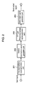
- FIG. 12 is a block diagram which shows configurations of a signal analysis filter bank and a signal synthesis filter bank.
- signal analysis filter bank 1201 includes sampling frequency K times interpolator 1203 and M analysis band-pass filters 1204 and M decimators 1205 .
- the signal synthesis filter bank 1202 includes M interpolators 1206 , M synthesis band-pass filters 1207 , adder 1208 , and sampling frequency 1/L times decimator 1209 .
- the analysis band-pass filter 1204 and the synthesis band-pass filter 1207 are paired each other.
- K and L are a divisor of number of bands M, and a positive integers including 1.
- it is also possible, in FIG. 12 to realize a configuration which does not have sampling frequency K times interpolator 1203 , or sampling frequency 1/L times decimator 1209 (i.e., such a configuration that a value of K or L is 1).
- sampling frequency K times interpolator 1203 by inserting (K ⁇ 1) zero data with respect to each data, to an input signal with sampling frequency fs, sampling frequency is elevated by K times, to become Kfs.
- this signal becomes band-pass signals by analysis band-pass filter 1204 which divides an entire band into M bands with equal bandwidth, and (M ⁇ 1) data are removed with respect to each M data, by decimator 1205 , and 1 piece data is outputted, and thereby, it is converted into a band signal with sampling frequency fsK/M, and outputted. Since sampling frequency of an input signal is set to K times, a band signal in (M/K)-th band or above is zero.
- a band signal with sampling frequency fsK/M which was outputted from signal analysis filter bank 1201 is used as an input, and (M ⁇ 1) zero data is inserted by interpolator 1206 with respect to each 1 piece of data, and thereby, sampling frequency is elevated to Kfs which is M times.
- This signal is converted into band-pass signals by M synthesis band-pass filters 1207 with equal bandwidth, and thereafter, they are synthesized by adder 1208 , so that a signal with sampling frequency Kfs is reproduced.
- decimator 1209 decimator 1209 , (L ⁇ 1) pieces of data are removed with respect to each L pieces of data, so that a signal with sampling frequency fsK/L is outputted.
- information compression is carried out between the signal analysis filter bank and the signal synthesis filter bank, through the use of deviation of distribution of a frequency direction of a band signal, and an auditory characteristic or a visual characteristic of humans to realize a high efficiency coding.
- the complex exponential modulation filter bank is configured by modulating a prototype filter with complex exponentials.
- a filter coefficient of a linear phase non-recursive type prototype filter is h(n) (0 ⁇ n ⁇ N, N is a filter order)
- a filter coefficient ha(k, n) of n sample in k-th band of a complex exponential modulation signal analysis filter bank is given by (formula 1) (j is imaginary unit, and A is phase for signal analysis).
- ha ( k,n ) Kh ( Kn )exp( j ⁇ ( k+ 0.5)(2 Kn+A )/(2 M )) (formula 1)
- FIG. 13 is a flow chart which shows processing steps of a conventional analyzing method of a complex exponential modulation signal analysis filter bank.
- step 1301 intermediate signal w(n) is calculated by (formula 3) from input signal x(n) at sampling time n.
- step 1302 complex band output signal X (k, mM/K) at sampling time mM/K in k-th band (0 ⁇ k ⁇ M/K ⁇ 1) is calculated by (formula 4) (A is phase for signal analysis) from intermediate signal w(n).
- pages 60 and 62 in the above-described ISO/IEC document describe an example of a complex exponential modulation signal analysis filter bank for such a case that number of bands M is 64, and filter order N of a prototype filter is 640, and scaling factor k of up-sampling is 2, and phase A of signals is ⁇ 1.
- this document uses c(n) which was calculated by (formula 5) from h(n), in lieu of filter coefficient h(n) of the prototype filter.
- c ( n ) ( ⁇ 1) INT(n/2M) h ( n ) (0 ⁇ n ⁇ N ⁇ 1) (formula 5)
- INT(x) is a function for making an integer with truncation of a fractional part of x.
- quantity of arithmetic operation which is necessary for realizing the complex exponential modulation signal analysis filter bank of FIG. 13 , is evaluated with number of real number addition and number of real number multiplication.
- the number of real number addition is 512 times and the number of real number multiplication is 640 times, in step 1301 , and the number of real number addition is 16256 times and the number of real number multiplication is 16384 times, in step 1302 , and as a total of combination of step 1301 and step 1302 , the number of real number addition is 16768 times and the number of real number multiplication is 17024 times.
- filter coefficient hs(k, n) of n sample in k-th band of a complex exponential modulation signal synthesis filter bank is given by (formula 6) (B is phase for signal synthesis).
- hs ( k,n ) (1 /M ) h ( Ln )exp( j ⁇ ( k+ 0.5)(2 Ln+B )/(2 M )) (formula 6)
- phase B for signal synthesis satisfies a relational formula of (formula 7) (P is arbitrary integer) with phase A for signal analysis.
- A+B+ 2 N 8 MP (formula 7)
- a real number part of summation in an effective band (band from 0-th band up to (M/L ⁇ 1)-th band) of such a signal that an input complex band signal is convolved with the filter coefficient of (formula 6) is an output of signal synthesis filter bank 1202 .
- values of filter coefficients of first and last prototype filters are set to zero, assuming that a complex band input signal at sample time mM/K in k-th band of a complex exponential modulation signal synthesis filter bank is X(k, mM/K), output signal x(mM/K+nL/K) at sampling time mM/K+nL/K is given by (formula 8) (Re(x) is an real part of complex number x).
- FIG. 14 is a flow chart which shows processing steps of a conventional synthesizing method of a complex exponential modulation signal synthesis filter bank.
- step 1401 intermediate signal w(n) of 0 ⁇ n ⁇ 2(N ⁇ M)/L ⁇ 1 is shifted to w(n+2M/L), and intermediate signal w(n) of 0 ⁇ n ⁇ 2M/L ⁇ 1 is calculated by (formula 9), from complex band input signal X(k, mM/K) at sampling time mM/K in k-th band.
- output signal x(mM/K+nL/K) at sampling time mM/K+nL/K (0 ⁇ n ⁇ M/L ⁇ 1) is calculated by (formula 10), from intermediate signal w(n).
- Pages 60, 61, and 63 of the above-described ISO/IEC document describe an example of a complex exponential modulation signal synthesis filter bank for such a case that number of bands M is 64, and filter order N of a prototype filter is 640, and scaling factor K of up-sampling is 2, and scaling factor 1/L of down-sampling is 1, and phase B for signal synthesis is ⁇ 255.
- Quantity of arithmetic operation which is necessary for realizing the complex exponential modulation signal synthesis filter bank of FIG. 14 , is evaluated with number of real number addition and number of real number multiplication.
- the number of real number addition is 16256 times and the number of real number multiplication is 16384 times, in step 1401 , and the number of real number addition is 576 times and the number of real number multiplication is 640 times, in step 1402 , and as a total of combination of step 1401 and step 1402 , the number of real number addition is 16832 times and the number of real number multiplication is 17024 times.
- a signal analyzing method of a complex exponential modulation filter bank is a signal analyzing method which makes up-sampling of an input signal with sampling frequency fs by K times, and divides it into M complex band signals with equal bandwidth and sampling frequency fsK/M to be outputted, and has a step of calculating a first intermediate signal from the input signal, a step of calculating a second intermediate signal from the first intermediate signal, a step of calculating a third intermediate signal from the second intermediate signal by fast Fourier transform, and a step of calculating a complex band output signal from the third intermediate signal.
- a signal synthesizing method of a complex exponential modulation filter bank is a signal synthesizing method which synthesizes complex band input signals, and makes down-sampling to 1/L times (Lisa divisor of M and a positive integer including 1), and outputs a signal with sampling frequency fsK/L, and has a step of calculating a first intermediate signal from the complex band input signal, a step of calculating a second intermediate signal from the first intermediate signal, with fast Fourier transform, a step of calculating a third intermediate signal from the second intermediate signal, and a step of calculating an output signal from the third intermediate signal.
- a program is a program for having a computer or a digital signal processor execute the above-described signal analyzing and synthesizing methods of a complex exponential modulation filter bank.
- a recording medium is a computer readable recording medium in which the above-described program for having a computer or a digital signal processor execute the above-described signal analyzing and synthesizing methods of a complex exponential modulation filter bank has been recorded.
- FIG. 1 is a flow chart which shows processing steps of a signal analyzing method of a complex exponential modulation filter bank in embodiment 1 of the invention
- FIG. 2 is a block diagram which shows a configuration of a device for carrying out the signal analyzing method of the complex exponential modulation filter bank in embodiment 1 of the invention
- FIG. 3 is a flow chart which shows processing steps of a signal analyzing method of a complex exponential modulation filter bank in embodiment 2 of the invention
- FIG. 4 is a flow chart which shows processing steps of a signal analyzing method of a complex exponential modulation filter bank in embodiment 3 of the invention
- FIG. 5 is a flow chart which shows processing steps of a signal analyzing method of a complex exponential modulation filter bank in embodiment 4 of the invention
- FIG. 6 is a flow chart which shows processing steps of a signal synthesizing method of a complex exponential modulation filter bank in embodiment 5 of the invention.
- FIG. 7 is a block diagram which shows a configuration of a device for carrying out the signal synthesizing method of the complex exponential modulation filter bank in embodiment 5 of the invention.
- FIG. 8 is a flow chart which shows processing steps of a signal synthesizing method of a complex exponential modulation filter bank in embodiment 6 of the invention.
- FIG. 9 is a flow chart which shows processing steps of a signal synthesizing method of a complex exponential modulation filter bank in embodiment 7 of the invention.
- FIG. 10 is a flow chart which shows processing steps of a signal synthesizing method of a complex exponential modulation filter bank in embodiment 8 of the invention.
- FIG. 11 is a flow chart which shows processing steps of a signal synthesizing method of a complex exponential modulation filter bank in embodiment 9 of the invention.
- FIG. 12 is a block diagram which shows configurations of a signal analysis filter bank and a signal synthesis filter bank
- FIG. 13 is a flow chart which shows processing steps of a conventional signal analyzing method of a complex exponential modulation filter bank
- FIG. 14 is a flow chart which shows processing steps of a conventional signal synthesizing method of a complex exponential modulation filter bank.
- the conventional signal analyzing method and signal synthesizing method of a complex exponential modulation filter bank have such a problem that quantity of arithmetic operation is large. Therefore, the conventional method has such a problem that operation clock frequency is heightened at the time of installing a filter bank by time-divisionally using the limited number of multipliers and adders as in a digital signal processor, so that electric power consumption is large. It also has such a problem that processing time is long at the time that a filter bank is executed by software, using a computer.
- the invention is to solve the above-described conventional problems, and it is its object to provide a signal analyzing method and a signal synthesizing method, by which quantity of arithmetic operation can be reduced at the time of complex exponential modulation filter bank execution, and electric power consumption can be reduced. It is another object of the invention to provide a signal analyzing method and a signal synthesizing method by which processing time was shortened and can speed up at the time of complex exponential modulation filter bank execution.
- a signal analyzing method of the invention is a signal analyzing method of a complex exponential modulation filter bank which makes up-sampling of an input signal with sampling frequency fs by K times, and divides it into M complex band signals with equal bandwidth and sampling frequency fsK/M to be outputted, and has a step of calculating a first intermediate signal from the input signal, a step of calculating a second intermediate signal from the first intermediate signal, a step of calculating a third intermediate signal from the second intermediate signal by fast Fourier transform or inverse fast Fourier transform at M/K points, and a step of calculating a complex band output signal from the third intermediate signal.
- a signal synthesizing method of the invention is a signal synthesizing method of a complex exponential modulation filter bank which synthesizes M complex band input signals with equal bandwidth and sampling frequency fsk/M, and makes down-sampling to 1/L times, and outputs a signal with sampling frequency fsK/L, and has a step of calculating a first intermediate signal from the complex band input signal, a step of calculating a second intermediate signal from the first intermediate signal, with fast Fourier transform or inverse fast Fourier transform at M/L point, and a step of shifting a third intermediate signal, and then, calculating the third intermediate signal from the second intermediate signal, and a step of calculating an output signal from the third intermediate signal.
- the signal analyzing method and signal synthesizing method of the invention handle a real number part and an imaginary part as a complex number without separating them, and therefore, by setting up phase for signal analysis or phase for signal synthesis in such a manner that quantity of arithmetic operation becomes small, it is possible to further reduce quantity of arithmetic operation.
- the invention it is possible to reduce quantity of arithmetic operation at the time of complex exponential modulation filter bank execution. Therefore, it is possible to reduce operation clock frequency when a filter bank is implemented in a digital signal processor and LSI, and it is possible to realize a complex exponential modulation filter bank with low electric power consumption. It is also possible to reduce processing time when a complex exponential modulation filter bank is executed by software, using a computer, and it is possible to realize speeding-up of processing.
- a signal analyzing method of a complex exponential modulation filter bank of the invention makes up-sampling of a signal with sampling frequency fs by K times (K is a divisor of number of bands M and a positive integer including 1), and divides it into M complex band signals with equal bandwidth and sampling frequency fsK/M.
- a signal synthesizing method of a complex exponential modulation filter bank of the invention synthesizes M complex band signals with equal bandwidth and sampling frequency fsK/M, and makes down-sampling to 1/L times (L is a divisor of M and a positive integer including 1), and outputs a signal with sampling frequency fsK/L.
- the complex exponential modulation filter bank is configured by applying complex exponential modulation to a prototype filter.
- FIG. 1 is a flow chart which shows processing steps of a signal analyzing method of a complex exponential modulation filter bank in embodiment 1 of the invention.
- a first intermediate signal is calculated from an input signal. Assuming that an input signal at sampling time n is x(n), a first intermediate signal w 1 (n)(0 ⁇ n ⁇ 2M/K ⁇ 1) is calculated by (formula 11) from the input signal.
- Step 101 is identical to step 1301 in the conventional example of FIG. 13 .
- c(n) which was calculated by (formula 12) in advance, is stored in a table and used, in lieu of h(n), (formula 11) becomes (formula 13).
- c ( n ) ( ⁇ 1) INT(n/2M) h ( n ) (0 ⁇ n ⁇ N ⁇ 1) (formula 12)
- a second intermediate signal w 2 (n)(0 ⁇ n ⁇ M/K ⁇ 1) is calculated from the first intermediate signal by (formula 14)(j is imaginary unit).
- w 2( n ) ( w 1( n ) ⁇ jw 1( n+M/K )) K exp( ⁇ j ⁇ nK /(2 M )) (0 ⁇ n ⁇ M/K ⁇ 1) (formula 14)
- a third intermediate signal W 3 (k)(0 ⁇ k ⁇ M/K ⁇ 1) is calculated from the second intermediate signal by fast Fourier transform (FFT) through the use of (formula 15).
- X (2 l,mM/K ) W 3*( l )exp( j ⁇ (4 l +1) A /(4 M )) (0 ⁇ l ⁇ M /(2 K ) ⁇ 1) (formula 16)
- X (2 l+ 1, mM/K ) W 3( M/K ⁇ 1 ⁇ l )exp( j ⁇ (4 l +3) A /(4 M )) (0 ⁇ l ⁇ M /(2 K ) ⁇ 1) (formula 17)
- an effective band of the complex band output signal is from 0-th band up to (M/K ⁇ 1)-th band, and the complex band output signal in M/K-th band or above is zero.
- step 104 In order to execute step 104 , complex multiplication with M/K times is necessary, and therefore, real number addition with 2M/K times and real number multiplication with 4M/K times are necessary.
- the number of arithmetic operation necessary for executing embodiment 1 of FIG. 1 is calculated by summation of the number of arithmetic operation in the above-described each step, the number of real number addition is N/K+2M/K+(3M/K)log 2 (M/K) times, and the number of real number multiplication is N/K+8M/K+(2M/K)log 2 (M/K) times.
- order N of a prototype filter is 640
- number of bands M is 64
- scaling factor K of up-sampling is 1
- quantity of arithmetic operation necessary for executing embodiment 1 is of 1920 times as the number of real number addition, and 1920 times as the number of real number multiplication.
- FIG. 2 is a block diagram which shows a configuration of a device which executes the signal analyzing method of the complex exponential modulation filter bank in embodiment 1.
- first intermediate signal generation part 201 executes (formula 13) from an input signal and filter coefficient of a prototype filter, to output a first intermediate signal.
- Second intermediate signal generation part 202 executes (formula 14) from the first intermediate signal which was outputted from first intermediate signal generation part 201 , to output a second intermediate signal.
- FFT part 203 executes (formula 15) by fast Fourier transform at M/K points to the second intermediate signal which was outputted from second intermediate signal generation part 202 , to output its result as a third intermediate signal.
- Band division output signal generation part 204 calculates and outputs a complex band output signal in accordance with (formula 16) and (formula 17) from the third intermediate signal which was outputted from FFT part 203 .
- the signal analyzing method of the complex exponential modulation filter bank in embodiment 1 it is possible to reduce quantity of arithmetic operation necessary for execution of a complex exponential modulation signal analysis filter bank, by effectively applying fast Fourier transform through the use of periodicity of a complex exponential function.
- it is possible to reduce operation clock frequency at the time of implementing a complex exponential modulation signal analysis filter bank in a digital signal processor and LSI it is possible to realize a complex exponential modulation signal analysis filter bank with low electric power consumption.
- FIG. 3 is a flow chart which shows processing steps of a signal analyzing method of a complex exponential modulation filter bank in embodiment 2 of the invention.
- Embodiment 2 is such a thing that phase A for signal analysis in embodiment 1 was set up to 8MP (P is arbitrary integer).
- Steps 301 , 302 and 303 of FIG. 3 are identical to steps 101 , 102 and 103 of FIG. 1 , respectively, and explanations will be omitted.
- X (2 l,mM/K ) W 3*( l ) (0 ⁇ l ⁇ M /(2 K ) ⁇ 1) (formula 20)
- X (2 l+ 1, mM/K ) W 3( M/K ⁇ 1 ⁇ l ) (0 ⁇ l ⁇ M /(2 K ) ⁇ 1) (formula 21)
- step 104 of FIG. 1 in embodiment 1 complex multiplication with M/K times is necessary, and real number addition with 2M/K times and real number multiplication with 4M/K times are necessary.
- step 304 complex multiplication is unnecessary, and quantity of arithmetic operation can be reduced by just that much.
- the number of arithmetic operation necessary for executing embodiment 2 of FIG. 3 is calculated by summation of the number of arithmetic operation in each step of FIG. 3 , the number of real number addition is N/K+(3M/K)log 2 (M/K) times, and the number of real number multiplication is N/K+4M/K+(2M/K)log 2 (M/K) times.
- order N of a prototype filter is 640
- number of bands M is 64
- scaling factor K of up-sampling is 1
- quantity of arithmetic operation necessary for executing embodiment 2 is of 1792 times as the number of real number addition, and 1664 times as the number of real number multiplication. Comparing this with embodiment 1, the number of real number addition is less by 128 times, and the number of real number multiplication is less by 256 times.
- phase A for signal analysis is set up to 8MP, but phase A of a signal may be set up to any one of the following (condition 2), (condition 3) and (condition 4).
- A 8MP (condition 1)
- A 2 M+ 8 MP (condition 2)
- A 4 M+ 8 MP (condition 3)
- A 6 M+ 8 MP (condition 4)
- phase A for signal analysis was set up to any one of (condition 2), (condition 3) and (condition 4), complex multiplication becomes unnecessary in a step of calculating a complex band output signal from the third intermediate signal, and it is possible to reduce quantity of arithmetic operation as compared with embodiment 1.
- To multiply with imaginary unit j in (formula 22) means to make a real number part as an imaginary part, and also, a sign of the imaginary part is inverted to be made as the real number part, so that multiplication is unnecessary.
- to multiply with ⁇ j in (formula 23) means to invert a sign of a real number part to be made as an imaginary part, and to make the imaginary part to the real number part, so that multiplication is unnecessary.
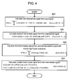
- FIG. 4 is a flow chart which shows processing steps of a signal analyzing method of a complex exponential modulation filter bank in embodiment 3 of the invention.
- reduced is quantity of arithmetic operation necessary for execution of the complex exponential modulation signal analysis filter bank, by effectively applying fast Fourier transform.
- reduced is quantity of arithmetic operation necessary for execution of the complex exponential modulation signal analysis filter bank by effectively applying inverse fast Fourier transform (IFFT).
- IFFT inverse fast Fourier transform
- second intermediate signal w 2 (n)(0 ⁇ n ⁇ M/K ⁇ 1) is calculated from the first intermediate signal by (formula 28).
- w 2( n ) ( w 1( n )+ jw 1( n+M/K )) K exp( ⁇ nK /(2 M )) (0 ⁇ n ⁇ M/K ⁇ 1) (formula 28)
- the number of complex multiplication necessary for executing step 402 is M/K times. If this is converted into real number operation, the number of real number addition is 2M/K times, and the number of real number multiplication is 4M/K times.
- step 403 third intermediate signal W 3 (k) (0 ⁇ k ⁇ M/K ⁇ 1) is calculated from the second intermediate signal with inverse fast Fourier transform by (formula 29).
- IFFT at M/K points requires butterfly operations with (M/(2K))log 2 (M/K) times in the same manner as in FFT. Therefore, the number of real number addition necessary for executing step 403 is (3M/K)log 2 (M/K) times, and the number of real number multiplication is (2M/K)log 2 (M/K) times.
- X (2 l,mM/K ) W 3( l )exp( j ⁇ (4 l+ 1) A /(4 M )) (0 ⁇ l ⁇ M /(2 K ) ⁇ 1) (formula 30)
- X (2 l+ 1, mM/K ) W 3*( M/K ⁇ 1 ⁇ l )exp( j ⁇ (4 l+ 3) A /(4 M )) (0 ⁇ l ⁇ M /(2 K ) ⁇ 1) (formula 31)
- step 404 In order to execute step 404 , complex multiplication by M/K times is necessary, and therefore, real number addition by 2M/K times and real number multiplication by 4M/K times are necessary.
- the number of arithmetic operation necessary for executing embodiment 3 of FIG. 4 is calculated by summation of the number of arithmetic operation in the above-described each step, the number of real number addition is N/K+2M/K+(3M/K)log 2 (M/K) times, and the number of real number multiplication is N/K+8M/K+(2M/K)log 2 (M/K) times. This is the same quantity of arithmetic operation as in embodiment 1.
- steps 402 , 403 and 404 in embodiment 3 can output identical result to step 1302 in FIG. 13 of the conventional example, by substituting (formula 28) for (formula 29) and by further substituting its substitution result for (formula 30) and (formula 31), in the same manner as described in embodiment 1.
- FIG. 5 is a flow chart which shows processing steps of a signal analyzing method of a complex exponential modulation filter bank in embodiment 4 of the invention.
- Embodiment 4 is of such a thing that phase A for signal analysis was set up to 8MP (P is an arbitrary integer) in embodiment 3.
- Steps 501 , 502 and 503 of FIG. 5 are identical to steps 401 , 402 and 403 of FIG. 4 , respectively, and explanations will be omitted.
- X (2 l,mM/K ) W 3( l ) (0 ⁇ l ⁇ M /(2 K ) ⁇ 1) (formula 32)
- X (2 l+ 1, mM/K ) W 3*( M/K ⁇ 1 ⁇ l ) (0 ⁇ l ⁇ M /(2 K ) ⁇ 1) (formula 33)
- step 404 of FIG. 4 complex multiplication by M/K times is necessary, and therefore, real number addition by 2M/K times and real number multiplication by 4M/K times are necessary.
- step 504 complex multiplication is unnecessary and quantity of arithmetic operation can be reduced by just that much.
- the number of arithmetic operation necessary for executing embodiment 4 of FIG. 5 is calculated by summation of the number of arithmetic operation in each step of FIG. 5 , the number of real number addition is N/K+(3M/K)log 2 (M/K) times, and the number of real number multiplication is N/K+4M/K+(2M/K)log 2 (M/K) times.
- order N of a prototype filter is 640
- number of bands M is 64
- scaling factor K of up-sampling is 1
- quantity of arithmetic operation necessary for executing embodiment 4 is of 1792 times as the number of real number addition, and 1664 times as the number of real number multiplication. Comparing this with embodiment 3, the number of real number addition is less by 128 times, and the number of real number multiplication is less by 256 times.
- phase A for signal analysis was set up to 8 MP, but phase A of a signal may be set up to any one of the following (condition 2), (condition 3) and (condition 4).
- A 8MP (condition 1)
- A 2 M+ 8 MP (condition 2)
- A 4 M+ 8 MP (condition 3)
- A 6 M+ 8 MP (condition 4)
- phase A for signal analysis was set up to any one of (condition 2), (condition 3) and (condition 4), complex multiplication becomes unnecessary in a step of calculating a complex band output signal from the third intermediate signal, and it is possible to reduce quantity of arithmetic operation as compared with embodiment 3.
- To multiply with imaginary unit j in (formula 34) means to make a real number part as an imaginary part, and also, a sign of the imaginary part is inverted to be made as the real number part, so that multiplication is unnecessary.
- to multiply with ⁇ j in (formula 35) means to invert a sign of a real number part to be made as an imaginary part, and to make the imaginary part to the real number part, so that multiplication is unnecessary.
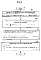
- FIG. 6 is a flow chart which shows processing steps of a signal synthesizing method of a complex exponential modulation filter bank in embodiment 5 of the invention.
- a first intermediate signal is calculated from a complex band input signal. Assuming that a complex band input signal at sampling time mM/K in k-th band is set to X(k, mM/K), first intermediate signal W 1 (k) is calculated from the complex band input signal by (formula 40) of 0 ⁇ k ⁇ M/(2L) ⁇ 1, and calculated by (formula 41) of M/(2L) ⁇ k ⁇ M/L ⁇ 1.
- W 1( k ) X *(2 k,mM/K )exp( ⁇ j ⁇ kB/M ) (0 ⁇ k ⁇ M /(2 L ) ⁇ 1) (formula 40)
- W 1( k ) X (2 M/L ⁇ 1 ⁇ 2 k,mM/K )exp( j ⁇ B (1/ L ⁇ k/M )) ( M /(2 L ) ⁇ k ⁇ M/L ⁇ 1) (formula 41)
- exp( ⁇ j ⁇ kB/M) and exp( ⁇ j ⁇ B(1/L ⁇ k/M)) are stored in a table and used, in order to execute step 601 , complex multiplication by M/L times is necessary, and if this is converted into real number operation, real number addition by 2M/L times and real number multiplication by 4M/L times are necessary.
- step 602 second intermediate signal w 2 (n) (0 ⁇ n ⁇ M/L ⁇ 1) is calculated from the first intermediate signal by fast Fourier transform through the use of (formula 43).
- step 602 the number of real number addition necessary for executing FFT at M/L point is (3M/L)log 2 (M/L) times, and the number of real number multiplication is (2M/L)log 2 (M/L) times.
- step 603 third intermediate signal w 3 (n) of 0 ⁇ n ⁇ 2(N ⁇ M)/L ⁇ 1 is shifted to w 3 (n+2M/L), and then, third intermediate signals w 3 (n) and w 3 (n+M/L) of 0 ⁇ n ⁇ M/L are calculated from the second intermediate signal by (formula 44) (Re(x) is an real part of a complex number x, and Im(x) is an imaginary part of x).
- step 603 assuming that (1/M)exp( ⁇ j ⁇ (2Ln+B)/(4M)) is stored in a table and used, in order to execute step 603 , complex multiplication by M/L times is necessary, and if this is converted into real number operation, real number addition by M/L times and real number multiplication by 4M/L times are necessary.
- step 604 an output signal x(mM/K+nL/K) at sampling time mM/K+nL/K(0 ⁇ n ⁇ M/L ⁇ 1) is calculated from the third intermediate signal by (formula 45).
- Step 604 is identical to step 1402 in the conventional example of FIG. 14 .
- the number of arithmetic operation necessary for executing embodiment 5 of FIG. 6 is calculated by summation of the number of arithmetic operation in the above-described each step, the number of real number addition is N/L+3M/L+(3M/L)log 2 (M/L) times, and the number of real number multiplication is N/L+8M/L+(2M/L)log 2 (M/L) times.
- order N of a prototype filter is 640
- number of bands M is 64
- scaling factor 1/L of down-sampling is 1, quantity of arithmetic operation necessary for executing embodiment 5 is of 1984 times as the number of real number addition, and 1920 times as the number of real number multiplication.
- a final formula of (Formula 49) is coincident with such a formula that w is substituted for w 3 in (formula 9) and a range of a value of n is set to 0 ⁇ n ⁇ M/L ⁇ 1.
- FIG. 7 is a block diagram of a device which executes the signal synthesizing method of the complex exponential modulation filter bank of embodiment 5.
- a first intermediate signal generation part outputs a first intermediate signal by executing (formula 40) and (formula 41) from a complex band input signal.
- FFT part 702 outputs a second intermediate signal by executing (formula 43) with fast Fourier transform at M/L point to the first intermediate signal which was outputted from first intermediate signal generation part 701 .
- Third intermediate signal generation part 703 executes (formula 44) from the second intermediate signal which was outputted from FFT part 702 , and outputs a third intermediate signal.
- an output signal is calculated by (formula 47) from the third intermediate signal which was outputted from third intermediate signal generation part 703 and filter coefficient of a prototype filter, and outputted.
- constant number 1/M was multiplied in step 603 , but this maybe modified in such a manner that it is multiplied in another step, e.g., in step 602 .
- FIG. 8 is a flow chart which shows processing steps of a signal synthesizing method of a complex exponential modulation filter bank in embodiment 6 of the invention.
- Embodiment 6 is of such a thing that phase B for signal synthesis was set up to ML in embodiment 5.
- Steps 802 and 804 of FIG. 8 are identical to steps 602 and 604 of FIG. 6 , and explanations will be omitted.
- a first intermediate signal is calculated from a complex band input signal. Assuming that a complex band input signal at sampling time mM/K in k-th band is set to X(k, mM/K), first intermediate signal W 1 (k) is calculated from the complex band input signal by (formula 51) of 0 ⁇ k ⁇ M/(2L) ⁇ 1, and calculated by (formula 52) of M/(2L) ⁇ k ⁇ M/L ⁇ 1.
- W 1( k ) X *(2 k,mM/K ) (0 ⁇ k ⁇ M /(2 L ) ⁇ 1) (formula 51)
- W 1( k ) X (2 M/L ⁇ 1 ⁇ 2 k,mM/K ) ( M /(2 L ) ⁇ k ⁇ M/L ⁇ 1) (formula 52)
- step 601 of FIG. 6 in embodiment 5 In order to execute step 601 of FIG. 6 in embodiment 5, complex multiplication by M/L times is necessary, and real number addition by 2M/L times and real number multiplication by 4M/L times are necessary. However, complex multiplication is unnecessary in step 801 , and quantity of arithmetic operation can be reduced by just that much.
- step 803 third intermediate signal w 3 (n) of 0 ⁇ n ⁇ 2(N ⁇ M)/L ⁇ 1 is shifted to w 3 (n+2M/L), and then, third intermediate signals w 3 (n) and w 3 (n+M/L) of 0 ⁇ n ⁇ M/L are calculated from the second intermediate signal by (formula 53).
- step 803 assuming that (1/M)exp( ⁇ j ⁇ L(n+M)/(2M)) is stored in a table and used, in order to execute step 803 , complex multiplication by M/L times is necessary, and if this is converted into real number operation, real number addition by 2M/L times and real number multiplication by 4M/L times are necessary. This number of arithmetic operation is identical to step 603 of FIG. 6 .
- the number of arithmetic operation necessary for executing embodiment 6 of FIG. 8 is calculated by summation of the number of arithmetic operation in the above-described each step, the number of real number addition is N/L+M/L+(3M/L)log 2 (M/L) times, and the number of real number multiplication is N/L+4M/L+(2M/L)log 2 (M/L) times.
- order N of a prototype filter is 640
- number of bands M is 64
- scaling factor 1/L of down-sampling is 1
- quantity of arithmetic operation necessary for executing embodiment 6 is of 1856 times as the number of real number addition, and 1664 times as the number of real number multiplication. Comparing this with embodiment 5, the number of real number addition is less by 128 times, and the number of real number multiplication is less by 256 times.
- FIG. 9 is a flow chart which shows processing steps of a signal synthesizing method of a complex exponential modulation filter bank in embodiment 7 of the invention.
- Embodiment 5 by effectively applying fast Fourier transform, quantity of arithmetic operation necessary for realizing a complex exponential modulation signal synthesis filter bank is reduced.
- embodiment 7 by effectively applying inverse fast Fourier transform, quantity of arithmetic operation necessary for realizing a complex exponential modulation signal synthesis filter bank is reduced.
- step 904 is identical to step 604 of FIG. 6 , and explanation will be omitted.
- a first intermediate signal is calculated from a complex band signal.
- first intermediate signal W 1 (k) is calculated from the complex band input signal by (formula 54) of 0 ⁇ k ⁇ M/(2L) ⁇ 1, and calculated by (formula 55) of M/(2L) ⁇ k ⁇ M/L ⁇ 1.
- B designates a phase for signal synthesis, and satisfies a relation formula of (formula 42) with phase A for signal analysis.
- W 1( k ) X (2 k,mM/K )exp( j ⁇ kB/M ) (0 ⁇ k ⁇ M /(2 L ) ⁇ 1) (formula 54)
- W 1( k ) X *(2 M/L ⁇ 1 ⁇ 2 k,mM/K )exp( j ⁇ B ( k/M ⁇ 1 /L )) ( M /(2 L ) ⁇ k ⁇ M/L ⁇ 1) (formula 55)
- exp(j ⁇ kB/M) and exp(j ⁇ B(k/M) ⁇ 1/L) are stored in a table and used, in order to execute step 901 , the number of complex multiplication by M/K times is necessary, and if this is converted into real number operation, the number of real number addition by 2M/L times, and the number of real number multiplication by 4M/L times are necessary.
- step 902 second intermediate signal W 2 (n)(0 ⁇ n ⁇ M/L ⁇ 1) is calculated from the first intermediate signal with inverse fast Fourier transform by (formula 56).
- step 902 the number of real number addition necessary for executing IFFT at M/L point is (3M/L)log 2 (M/L) times, and the number of real number multiplication is (2M/L)log 2 (M/L) times.
- step 903 third intermediate signal w 3 (n) of 0 ⁇ n ⁇ 2(N ⁇ M)/L ⁇ 1 is shifted to w 3 (n+2M/L), and then, third intermediate signals w 3 (n) and w 3 (n+M/L) of 0 ⁇ n ⁇ M/L are calculated from the second intermediate signal by (formula 57).
- step 903 assuming that (1/M)exp(j ⁇ (2Ln+B)/(4M)) is stored in a table and used, in order to execute step 903 , complex multiplication by M/L times is necessary, and if this is converted into real number operation, real number addition by 2M/L times and real number multiplication by 4M/L times are necessary.
- the number of arithmetic operation necessary for executing embodiment 7 of FIG. 9 is calculated by summation of the number of arithmetic operation in the above-described each step, the number of real number addition is N/L+3M/L+(3M/L)log 2 (M/L) times, and the number of real number multiplication is N/L+8M/L+(2M/L)log 2 (M/L) times. This is the same quantity of arithmetic operation as in embodiment 5.
- steps 901 , 902 and 903 in embodiment 7 can output identical result to step 1401 in FIG. 14 of the conventional example, by substituting (formula 54) and (formula 55) for (formula 56) and by further substituting its substitution result for (formula 57), in the same manner as described in embodiment 5.
- FIG. 10 is a flow chart which shows processing steps of a signal synthesizing method of a complex exponential modulation filter bank in embodiment 8 of the invention.
- Embodiment 8 is of such a thing that phase B for signal synthesis was set up to ML in embodiment 7.
- Steps 1002 and 1004 of FIG. 10 are identical to steps 902 and 904 of FIG. 9 , respectively, and explanations will be omitted.
- a first intermediate signal is calculated from a complex band input signal. Assuming that a complex band input signal at sampling time mM/K in k-th band is set to X(k, mM/K), first intermediate signal W 1 (k) is calculated from the complex band input signal by (formula 58) of 0 ⁇ k ⁇ M/(2L) ⁇ 1, and calculated by (formula 59) of M/(2L) ⁇ k ⁇ M/L ⁇ 1.
- W 1( k ) X (2 k,mM/K ) (0 ⁇ k ⁇ M /(2 L ) ⁇ 1) (formula 58)
- W 1( k ) X *(2 M/L ⁇ 1 ⁇ 2 k,mM/K ) ( M /(2 L ) ⁇ k ⁇ M/L ⁇ 1) (formula 59)
- step 901 of FIG. 9 complex multiplication by M/L times is necessary, and real number addition by 2M/L times and real number multiplication by 4M/L times are necessary.
- step 1001 complex multiplication is unnecessary, and quantity of arithmetic operation can be reduced by just that much.
- step 1003 third intermediate signal w 3 (n) of 0 ⁇ n ⁇ 2(N ⁇ M)/L ⁇ 1 is shifted to w 3 (n+2M/L), and then, third intermediate signals w 3 (n) and w 3 (n+M/L) of 0 ⁇ n ⁇ M/L are calculated from the second intermediate signal by (formula 60)
- w 3( n ) Re ⁇ w 2( n )(1 /M )exp( j ⁇ L ( n+M )/(2 M )) ⁇
- w 3( n+M/L ) ⁇ Im ⁇ w 2( n )(1 /M )exp( j ⁇ L ( n+M )/(2 M )) ⁇ (0 ⁇ n ⁇ M/L ⁇ 1) (formula 60)
- step 1003 assuming that (1/M)exp(j ⁇ L(n+M)/(2M)) is stored in a table and used, in order to execute step 1003 , complex multiplication by M/L times is necessary, and if this is converted into real number operation, real number addition by 2M/L times and real number multiplication by 4M/L times are necessary. This result of arithmetic operation is identical to step 903 of FIG. 9 .
- the number of arithmetic operation necessary for executing embodiment 8 of FIG. 10 is calculated by summation of the number of arithmetic operation in the above-described each step, the number of real number addition is N/L+M/L+(3M/L)log 2 (M/L) times, and the number of real number multiplication is N/L+4M/L+(2M/L)log 2 (M/L) times.
- order N of a prototype filter is 640
- number of bands M is 64
- scaling factor 1/L of down-sampling is 1
- quantity of arithmetic operation necessary for executing embodiment 8 is of 1856 times as the number of real number addition, and 1664 times as the number of real number multiplication. Comparing this with embodiment 7, the number of real number addition is less by 128 times, and the number of real number multiplication is less by 256 times.
- the signal synthesizing method of the complex exponential modulation filter bank of embodiment 8 sets up the phase for signal synthesis in such a manner that there occurs no multiplication in a step of calculating the first intermediate signal from the complex band input signal. By doing this, it is possible to further reduce quantity of arithmetic operation, as compared with embodiment 7.
- FIG. 11 is a flow chart which shows processing steps of a signal synthesizing method of a complex exponential modulation filter bank in embodiment 9 of the invention.
- Steps 1102 and 1104 of FIG. 11 are identical to steps 602 and 604 of FIG. 6 , respectively, and explanations will be omitted.
- a first intermediate signal is calculated from a complex band input signal. Assuming that the complex band input signal at sampling time mM/K in k-th band is set to X(k, mM/K), first intermediate signal W 1 (k) is calculated from the complex band input signal by (formula 61) of 0 ⁇ k ⁇ M/(2L) ⁇ 1, and calculated by (formula 62) of M/(2L) ⁇ k ⁇ M/L ⁇ 1.
- W 1( k ) X *(2 l,mM/K )exp( ⁇ j ⁇ B (4 k+ 1)/(4 M )) (0 ⁇ k ⁇ M /(2 L ) ⁇ 1) (formula 61)
- W 1( k ) X (2 M/L ⁇ 1 ⁇ 2 k,mM/K )exp( j ⁇ B (1 /L ⁇ (4 k+ 1)/(4 M ))) ( M /(2 L ) ⁇ k ⁇ M/L ⁇ 1) (formula 62)
- step 1101 is of such a thing that exp( ⁇ j ⁇ B/(4M)) was multiplied with step 601 .
- step 1103 third intermediate signal w 3 (n) of 0 ⁇ n ⁇ 2(N ⁇ M)/L ⁇ 1 is shifted to w 3 (n+2M/L), and then, third intermediate signals w 3 (n) and w 3 (n+M/L) of 0 ⁇ n ⁇ M/L are calculated from the second intermediate signal by (formula 63).
- step 1103 is of such a thing that exp(j ⁇ B/(4M)) was multiplied with step 603 .
- Embodiment 9 of FIG. 11 is comparable to such a thing that constant number exp( ⁇ j ⁇ B/(4M)) was multiplied in step 601 of FIG. 6 , and inverse number exp(j ⁇ B/(4M)) of the constant number was multiplied in step 603 . If the constant number is multiplied in the former step, and the inverse number of the constant number is multiplied in the latter step, it is possible to obtain a result which is the same as original. Therefore, embodiment 9 of FIG. 11 can obtain an identical result to embodiment 5 of FIG. 6 .
- the signal analyzing and signal synthesizing method in the above-described each embodiment can be realized as a program for having a computer or a digital signal processor execute it, and this may be recorded on a computer readable recording medium.
- a signal analyzing and signal synthesizing method of a complex exponential modulation filter bank which relates to the invention is useful as high efficiency coding of audio signals and image signals and a signal analyzing and signal synthesizing method for a digital equalizer etc., and in particular, suitable for realizing a complex exponential modulation filter bank with low electric power consumption or high speed, by reducing quantity of arithmetic operation.
Abstract
Description
ha(k,n)=Kh(Kn)exp(jπ(k+0.5)(2Kn+A)/(2M)) (formula 1)
c(n)=(−1)INT(n/2M) h(n) (0≦n≦N−1) (formula 5)
hs(k,n)=(1/M)h(Ln)exp(jπ(k+0.5)(2Ln+B)/(2M)) (formula 6)
A+B+2N=8MP (formula 7)
c(n)=(−1)INT(n/2M) h(n) (0≦n≦N−1) (formula 12)
w2(n)=(w1(n)−jw1(n+M/K))K exp(−jπnK/(2M)) (0≦n≦M/K−1) (formula 14)
X(2l,mM/K)=W3*(l)exp(jπ(4l+1)A/(4M)) (0≦l≦M/(2K)−1) (formula 16)
X(2l+1,mM/K)=W3(M/K−1−l)exp(jπ(4l+3)A/(4M)) (0≦l≦M/(2K)−1) (formula 17)
X(2l,mM/K)=W3*(l) (0≦l≦M/(2K)−1) (formula 20)
X(2l+1,mM/K)=W3(M/K−1−l) (0≦l≦M/(2K)−1) (formula 21)
A=8MP (condition 1)
A=2M+8MP (condition 2)
A=4M+8MP (condition 3)
A=6M+8MP (condition 4)
X(2l,mM/K)=jW3*(l) (0≦l≦M/(2K)−1) (formula 22)
X(2l+1,mM/K)=−jW3(M/K−1−l) (0≦l≦M/(2K)−1) (formula 23)
X(2l,mM/K)=−W3*(l) (0≦l≦M/(2K)−1) (formula 24)
X(2l+1,mM/K)=−W3(M/K−1−l) (0≦l≦M/(2K)−1) (formula 25)
X(2l,mM/K)=−jW3*(l) (0≦l≦M/(2K)−1) (formula 26)
X(2l+1,mM/K)=jW3(M/K−1−l) (0≦l≦M/(2K)−1) (formula 27)
w2(n)=(w1(n)+jw1(n+M/K))K exp(πnK/(2M)) (0≦n≦M/K−1) (formula 28)
X(2l,mM/K)=W3(l)exp(jπ(4l+1)A/(4M)) (0≦l≦M/(2K)−1) (formula 30)
X(2l+1,mM/K)=W3*(M/K−1−l)exp(jπ(4l+3)A/(4M)) (0≦l≦M/(2K)−1) (formula 31)
X(2l,mM/K)=W3(l) (0≦l≦M/(2K)−1) (formula 32)
X(2l+1,mM/K)=W3*(M/K−1−l) (0≦l≦M/(2K)−1) (formula 33)
A=8MP (condition 1)
A=2M+8MP (condition 2)
A=4M+8MP (condition 3)
A=6M+8MP (condition 4)
X(2l,mM/K)=jW3(l) (0≦l≦M/(2K)−1) (formula 34)
X(2l+1,mM/K)=−jW3*(M/K−1−l) (0≦l≦M/(2K)−1) (formula 35)
X(2l,mM/K)=−W3(l) (0≦l≦M/(2K)−1) (formula 36)
X(2l+1,mM/K)=−W3*(M/K−1−l) (0≦l≦M/(2K)−1) (formula 37)
X(2l,mM/K)=−jW3(l) (0≦l≦M/(2K)−1) (formula 38)
X(2l+1,mM/K)=jW3*(M/K−1−l) (0≦l≦M/(2K)−1) (formula 39)
W1(k)=X*(2k,mM/K)exp(−jπkB/M) (0≦k≦M/(2L)−1) (formula 40)
W1(k)=X(2M/L−1−2k,mM/K)exp(jπB(1/L−k/M)) (M/(2L)≦k≦M/L−1) (formula 41)
A+B+2N=8MP (formula 42)
w3(n)=Re{w2(n)(1/M)exp(−jπ(2Ln+B)/(4M))}
w3(n+M/L)=Im{w2(n)(1/M)exp(−jπ(2Ln+B)/(4M))} (0≦n≦M/L−1) (formula 44)
c(n)=(−1)INT(n/2M) h(n) (0≦n≦N−1) (formula 46)
W1(k)=X*(2k,mM/K) (0≦k≦M/(2L)−1) (formula 51)
W1(k)=X(2M/L−1−2k,mM/K) (M/(2L)≦k≦M/L−1) (formula 52)
w3(n)=Re{w2(n)(1/M)exp(−jπL(n+M)/(2M))}
w3(n+M/L)=Im{w2(n)(1/M)exp(−jπL(n+M)/(2M))} (0≦n≦M/L−1) (formula 53)
W1(k)=X(2k,mM/K)exp(jπkB/M) (0≦k≦M/(2L)−1) (formula 54)
W1(k)=X*(2M/L−1−2k,mM/K)exp(jπB(k/
w3(n)=Re{w2(n)1/M)exp(jπ(2Ln+B)/(4M))}
w3(n+M/L)=−Im{w2(n)(1/M)exp(jπ(2Ln+B)/(4M))} (0≦n≦M/L−1) (formula 57)
W1(k)=X(2k,mM/K) (0≦k≦M/(2L)−1) (formula 58)
W1(k)=X*(2M/L−1−2k,mM/K) (M/(2L)≦k≦M/L−1) (formula 59)
w3(n)=Re{w2(n)(1/M)exp(jπL(n+M)/(2M))}
w3(n+M/L)=−Im{w2(n)(1/M)exp(jπL(n+M)/(2M))} (0≦n≦M/L−1) (formula 60)
W1(k)=X*(2l,mM/K)exp(−jπB(4k+1)/(4M)) (0≦k≦M/(2L)−1) (formula 61)
W1(k)=X(2M/L−1−2k,mM/K)exp(jπB(1/L−(4k+1)/(4M))) (M/(2L)≦k≦M/L−1) (formula 62)
w3(n)=Re{w2(n)(1/M)exp(−jπLn/(2M))}
w3(n+M/L)=Im{w2(n)(1/M)exp(−jπLn/(2M))} (0≦n≦M/L−1) (formula 63)
Claims (12)
w2(n)=(w1(n)−jw1(n+M/K))K exp(−jπnK/(2M))(0≦n≦M/K−1) (formula 2)
X(2l,mM/K)=W3*(l)exp(jπ(4l+1)A/(4M)) (0≦l≦M/(2K)−1) (formula 4)
X(2l+1,mM/K)=W3(M/K−1−l)exp(jπ(4l+3)A/(4M)) (0≦l≦M/(2K)−1) (formula 5).
w2(n)=(w1(n)+jw1(n+M/K))K exp(jπnK/(2M)) (0≦n≦M/K−1) (formula 7)
X(2l,mM/K)=W3(l)exp(jπ(4l+1)A/(4M)) (0≦l≦M/(2K)−1) (formula 9)
X(2l+1,mM/K)=W3*(M/K−1−l)exp(jπ(4l+3)A/(4M)) (0≦l≦M/(2K)−1) (formula 10).
W1(k)=X*(2k,mM/K)exp(−jπkB/M) (0≦k≦M/(2L)−1) (formula 11)
W1(k)=X(2M/L−1−2k,mM/K)exp(jπB(1/L−k/M)) (M/(2L)≦k≦M/L−1) (formula 12)
w3(n)=Re{w2(n)(1/M)exp(−jπ(2Ln+B)/(4M))}
w3(n+M/L)=Im{w2(n)(1/M)exp(−jπ(2Ln+B)/(4M))} (0≦n≦M/L−1) (formula 14)
W1(k)=X(2k,mM/K)exp(jπkB/M) (0≦k≦M/(2L)−1) (formula 16)
W1(k)=X*(2M/L−1−2k,mM/K)exp(jπB(k/M−1/L)) (M/(2L)≦k≦M/L−1) (formula 17)
w3(n)=Re{w2(n)(1/M)exp(jπ(2Ln+B)/(4M))}
w3(n+M/L)=−Im{w2(n)(1/M)exp(jπ(2Ln+B)/(4M))} (0≦n≦M/L−1) (formula 19)
w2(n)=(w1(n)−jw1(n+M/K))K exp(−jπnK/(2M)) (0≦n≦M/K−1) (formula 2)
X(2l,mM/K)=W3*(l)exp(jπ(4l+1)A/(4M)) (0≦l≦M/(2K)−1) (formula 4)
X(2l+1,mM/K)=W3(M/K−1−l)exp(jπ(4l+3)A/(4M)) (0≦l≦M/(2K)−1) (formula 5).
w2(n)=(w1(n)+jw1(n+M/K))K exp(jπnK/(2M)) (0≦n≦M/K−1) (formula 7)
X(2l,mM/K)=W3(l)exp(jπ(4l+1)A/(4M)) (0≦l≦M/(2K)−1) (formula 9)
X(2l+1,mM/K)=W3*(M/K−1−l)exp(jπ(4l+3)A/(4M)) (0≦l≦M/(2K)−1) (formula 10).
W1(k)=X*(2k,mM/K)exp(−jπkB/M) (0≦k≦M/(2L)−1) (formula 11)
W1(k)=X(2M/L−1−2k,mM/K)exp(jπ(1/L−k/M)) (M/(2L)≦k≦M/L−1) (formula 12)
w3(n)=Re{w2(n)(1/M)exp(−jπ(2Ln+B)/(4M))}
w3(n+M/L)=Im{w2(n)(1/M)exp(−jπ(2Ln+B)/(4M))} (0≦n≦M/L−1) (formula 14)
W1(k)=X(2k,mM/K)exp(jπkB/M) (0≦k≦M/(2L)−1) (formula 16)
W1(k)=X*(2M/L−1−2k,mM/K)exp(jπB(k/M−1/L)) (M/(2L)≦k≦M/L−1) (formula 17)
w3(n)=Re{w2(n)(1/M)exp(jπ(2Ln+B)/(4M))}
w3(n+M/L)=−Im{w2(n)(1/M)exp(jπ(2Ln+B)/(4M))} (0≦n≦M/L−1) (formula 19)
Applications Claiming Priority (2)
| Application Number | Priority Date | Filing Date | Title |
|---|---|---|---|
| JP2003-383535 | 2003-11-13 | ||
| JP2003383535A JP4396233B2 (en) | 2003-11-13 | 2003-11-13 | Complex exponential modulation filter bank signal analysis method, signal synthesis method, program thereof, and recording medium thereof |
Publications (2)
| Publication Number | Publication Date |
|---|---|
| US20050108002A1 US20050108002A1 (en) | 2005-05-19 |
| US7433907B2 true US7433907B2 (en) | 2008-10-07 |
Family
ID=34567305
Family Applications (1)
| Application Number | Title | Priority Date | Filing Date |
|---|---|---|---|
| US10/986,624 Expired - Fee Related US7433907B2 (en) | 2003-11-13 | 2004-11-12 | Signal analyzing method, signal synthesizing method of complex exponential modulation filter bank, program thereof and recording medium thereof |
Country Status (2)
| Country | Link |
|---|---|
| US (1) | US7433907B2 (en) |
| JP (1) | JP4396233B2 (en) |
Cited By (25)
| Publication number | Priority date | Publication date | Assignee | Title |
|---|---|---|---|---|
| US20070100612A1 (en) * | 2005-09-16 | 2007-05-03 | Per Ekstrand | Partially complex modulated filter bank |
| US20070154031A1 (en) * | 2006-01-05 | 2007-07-05 | Audience, Inc. | System and method for utilizing inter-microphone level differences for speech enhancement |
| US20090012783A1 (en) * | 2007-07-06 | 2009-01-08 | Audience, Inc. | System and method for adaptive intelligent noise suppression |
| US20090220107A1 (en) * | 2008-02-29 | 2009-09-03 | Audience, Inc. | System and method for providing single microphone noise suppression fallback |
| US20090238373A1 (en) * | 2008-03-18 | 2009-09-24 | Audience, Inc. | System and method for envelope-based acoustic echo cancellation |
| US20100033888A1 (en) * | 2008-08-08 | 2010-02-11 | General Electric Company | Circuit breaker with arc fault detection and method of operation |
| US20100169104A1 (en) * | 2005-09-16 | 2010-07-01 | Per Ekstrand | Partially Complex Modulated Filter Bank |
| US8189766B1 (en) | 2007-07-26 | 2012-05-29 | Audience, Inc. | System and method for blind subband acoustic echo cancellation postfiltering |
| US8194880B2 (en) | 2006-01-30 | 2012-06-05 | Audience, Inc. | System and method for utilizing omni-directional microphones for speech enhancement |
| US8204252B1 (en) | 2006-10-10 | 2012-06-19 | Audience, Inc. | System and method for providing close microphone adaptive array processing |
| US8204253B1 (en) | 2008-06-30 | 2012-06-19 | Audience, Inc. | Self calibration of audio device |
| US8259926B1 (en) | 2007-02-23 | 2012-09-04 | Audience, Inc. | System and method for 2-channel and 3-channel acoustic echo cancellation |
| US8521530B1 (en) | 2008-06-30 | 2013-08-27 | Audience, Inc. | System and method for enhancing a monaural audio signal |
| US9008329B1 (en) | 2010-01-26 | 2015-04-14 | Audience, Inc. | Noise reduction using multi-feature cluster tracker |
| US9076456B1 (en) | 2007-12-21 | 2015-07-07 | Audience, Inc. | System and method for providing voice equalization |
| US9185487B2 (en) | 2006-01-30 | 2015-11-10 | Audience, Inc. | System and method for providing noise suppression utilizing null processing noise subtraction |
| CN105337587A (en) * | 2015-11-10 | 2016-02-17 | 哈尔滨工程大学 | Non maximum extraction system integrated filter bank construction method based on DFT |
| US9306606B2 (en) * | 2014-06-10 | 2016-04-05 | The Boeing Company | Nonlinear filtering using polyphase filter banks |
| US9536540B2 (en) | 2013-07-19 | 2017-01-03 | Knowles Electronics, Llc | Speech signal separation and synthesis based on auditory scene analysis and speech modeling |
| US9640194B1 (en) | 2012-10-04 | 2017-05-02 | Knowles Electronics, Llc | Noise suppression for speech processing based on machine-learning mask estimation |
| US9799330B2 (en) | 2014-08-28 | 2017-10-24 | Knowles Electronics, Llc | Multi-sourced noise suppression |
| US9820042B1 (en) | 2016-05-02 | 2017-11-14 | Knowles Electronics, Llc | Stereo separation and directional suppression with omni-directional microphones |
| US9830899B1 (en) | 2006-05-25 | 2017-11-28 | Knowles Electronics, Llc | Adaptive noise cancellation |
| US9838784B2 (en) | 2009-12-02 | 2017-12-05 | Knowles Electronics, Llc | Directional audio capture |
| US9978388B2 (en) | 2014-09-12 | 2018-05-22 | Knowles Electronics, Llc | Systems and methods for restoration of speech components |
Families Citing this family (10)
| Publication number | Priority date | Publication date | Assignee | Title |
|---|---|---|---|---|
| US7027942B1 (en) * | 2004-10-26 | 2006-04-11 | The Mitre Corporation | Multirate spectral analyzer with adjustable time-frequency resolution |
| ES2750304T3 (en) * | 2006-01-27 | 2020-03-25 | Dolby Int Ab | Efficient filtration with a complex modulated filter bank |
| US8150065B2 (en) * | 2006-05-25 | 2012-04-03 | Audience, Inc. | System and method for processing an audio signal |
| EP2603913B1 (en) | 2010-08-12 | 2014-06-11 | Fraunhofer Gesellschaft zur Förderung der angewandten Forschung e.V. | Resampling output signals of qmf based audio codecs |
| US9778902B2 (en) * | 2011-10-27 | 2017-10-03 | Intel Corporation | Software digital front end (SoftDFE) signal processing |
| RU2012102842A (en) | 2012-01-27 | 2013-08-10 | ЭлЭсАй Корпорейшн | INCREASE DETECTION OF THE PREAMBLE |
| US9813223B2 (en) | 2013-04-17 | 2017-11-07 | Intel Corporation | Non-linear modeling of a physical system using direct optimization of look-up table values |
| US9923595B2 (en) | 2013-04-17 | 2018-03-20 | Intel Corporation | Digital predistortion for dual-band power amplifiers |
| KR101824399B1 (en) * | 2015-12-30 | 2018-02-01 | 어보브반도체 주식회사 | Bluetooth signal receiving method and device using improved packet detection and symbol timing acquisition |
| CN112383497B (en) * | 2020-11-10 | 2023-02-14 | 展讯半导体(成都)有限公司 | OFDM conversion method in 5G system and related product |
Citations (7)
| Publication number | Priority date | Publication date | Assignee | Title |
|---|---|---|---|---|
| WO2002080362A1 (en) | 2001-04-02 | 2002-10-10 | Coding Technologies Sweden Ab | Aliasing reduction using complex-exponential modulated filterbanks |
| US6690717B1 (en) * | 1999-12-14 | 2004-02-10 | Electronics And Telecommunications Research Institute | Multi-tone transceiver system using two steps of DMT-CMFB |
| US20040042557A1 (en) * | 2002-08-29 | 2004-03-04 | Kabel Allan M. | Partial band reconstruction of frequency channelized filters |
| US6856653B1 (en) * | 1999-11-26 | 2005-02-15 | Matsushita Electric Industrial Co., Ltd. | Digital signal sub-band separating/combining apparatus achieving band-separation and band-combining filtering processing with reduced amount of group delay |
| US6952446B1 (en) * | 2001-12-10 | 2005-10-04 | The United States Of America As Represented By The Secretary Of The Air Force | Digital filter bank followed by monobit receivers for signal processing |
| US7043512B2 (en) * | 2002-02-01 | 2006-05-09 | Korea Advanced Institute Of Science And Technology | Filter bank approach to adaptive filtering method using independent component analysis |
| US7290021B2 (en) * | 2001-04-24 | 2007-10-30 | California Institute Of Technology | Method and apparatus for parallel signal processing |
-
2003
- 2003-11-13 JP JP2003383535A patent/JP4396233B2/en not_active Expired - Fee Related
-
2004
- 2004-11-12 US US10/986,624 patent/US7433907B2/en not_active Expired - Fee Related
Patent Citations (7)
| Publication number | Priority date | Publication date | Assignee | Title |
|---|---|---|---|---|
| US6856653B1 (en) * | 1999-11-26 | 2005-02-15 | Matsushita Electric Industrial Co., Ltd. | Digital signal sub-band separating/combining apparatus achieving band-separation and band-combining filtering processing with reduced amount of group delay |
| US6690717B1 (en) * | 1999-12-14 | 2004-02-10 | Electronics And Telecommunications Research Institute | Multi-tone transceiver system using two steps of DMT-CMFB |
| WO2002080362A1 (en) | 2001-04-02 | 2002-10-10 | Coding Technologies Sweden Ab | Aliasing reduction using complex-exponential modulated filterbanks |
| US7290021B2 (en) * | 2001-04-24 | 2007-10-30 | California Institute Of Technology | Method and apparatus for parallel signal processing |
| US6952446B1 (en) * | 2001-12-10 | 2005-10-04 | The United States Of America As Represented By The Secretary Of The Air Force | Digital filter bank followed by monobit receivers for signal processing |
| US7043512B2 (en) * | 2002-02-01 | 2006-05-09 | Korea Advanced Institute Of Science And Technology | Filter bank approach to adaptive filtering method using independent component analysis |
| US20040042557A1 (en) * | 2002-08-29 | 2004-03-04 | Kabel Allan M. | Partial band reconstruction of frequency channelized filters |
Non-Patent Citations (1)
| Title |
|---|
| ISO/IEC 14496-3: 2001, Information technology-Coding of audio-visual objects-Part 3: Audio, ISO/IEC JTC1/SC29/WG11/N5570, Mar. 2003 (Text of ISO/IEC 14496-3:2001/FDAM1, Bandwidth Extension). |
Cited By (41)
| Publication number | Priority date | Publication date | Assignee | Title |
|---|---|---|---|---|
| US8180819B2 (en) | 2005-09-16 | 2012-05-15 | Dolby International Ab | Partially complex modulated filter bank |
| US8756266B2 (en) | 2005-09-16 | 2014-06-17 | Dolby International Ab | Partially complex modulated filter bank |
| US8443026B2 (en) | 2005-09-16 | 2013-05-14 | Dolby International Ab | Partially complex modulated filter bank |
| US20070100612A1 (en) * | 2005-09-16 | 2007-05-03 | Per Ekstrand | Partially complex modulated filter bank |
| US8285771B2 (en) | 2005-09-16 | 2012-10-09 | Dolby International Ab | Partially complex modulated filter bank |
| US8180818B2 (en) | 2005-09-16 | 2012-05-15 | Dolby International Ab | Partially complex modulated filter bank |
| US20100169104A1 (en) * | 2005-09-16 | 2010-07-01 | Per Ekstrand | Partially Complex Modulated Filter Bank |
| US20100179814A1 (en) * | 2005-09-16 | 2010-07-15 | Per Ekstrand | Partially complex modulated filter bank |
| US20100228555A1 (en) * | 2005-09-16 | 2010-09-09 | Per Ekstrand | Partially Complex Modulated Filter Bank |
| US7917561B2 (en) | 2005-09-16 | 2011-03-29 | Coding Technologies Ab | Partially complex modulated filter bank |
| US20110106541A1 (en) * | 2005-09-16 | 2011-05-05 | Per Ekstrand | Partially Complex Modulated Filter Bank |
| US8345890B2 (en) | 2006-01-05 | 2013-01-01 | Audience, Inc. | System and method for utilizing inter-microphone level differences for speech enhancement |
| US8867759B2 (en) | 2006-01-05 | 2014-10-21 | Audience, Inc. | System and method for utilizing inter-microphone level differences for speech enhancement |
| US20070154031A1 (en) * | 2006-01-05 | 2007-07-05 | Audience, Inc. | System and method for utilizing inter-microphone level differences for speech enhancement |
| US9185487B2 (en) | 2006-01-30 | 2015-11-10 | Audience, Inc. | System and method for providing noise suppression utilizing null processing noise subtraction |
| US8194880B2 (en) | 2006-01-30 | 2012-06-05 | Audience, Inc. | System and method for utilizing omni-directional microphones for speech enhancement |
| US9830899B1 (en) | 2006-05-25 | 2017-11-28 | Knowles Electronics, Llc | Adaptive noise cancellation |
| US8204252B1 (en) | 2006-10-10 | 2012-06-19 | Audience, Inc. | System and method for providing close microphone adaptive array processing |
| US8259926B1 (en) | 2007-02-23 | 2012-09-04 | Audience, Inc. | System and method for 2-channel and 3-channel acoustic echo cancellation |
| US20090012783A1 (en) * | 2007-07-06 | 2009-01-08 | Audience, Inc. | System and method for adaptive intelligent noise suppression |
| US8886525B2 (en) | 2007-07-06 | 2014-11-11 | Audience, Inc. | System and method for adaptive intelligent noise suppression |
| US8744844B2 (en) | 2007-07-06 | 2014-06-03 | Audience, Inc. | System and method for adaptive intelligent noise suppression |
| US8189766B1 (en) | 2007-07-26 | 2012-05-29 | Audience, Inc. | System and method for blind subband acoustic echo cancellation postfiltering |
| US9076456B1 (en) | 2007-12-21 | 2015-07-07 | Audience, Inc. | System and method for providing voice equalization |
| US8194882B2 (en) | 2008-02-29 | 2012-06-05 | Audience, Inc. | System and method for providing single microphone noise suppression fallback |
| US20090220107A1 (en) * | 2008-02-29 | 2009-09-03 | Audience, Inc. | System and method for providing single microphone noise suppression fallback |
| US20090238373A1 (en) * | 2008-03-18 | 2009-09-24 | Audience, Inc. | System and method for envelope-based acoustic echo cancellation |
| US8355511B2 (en) | 2008-03-18 | 2013-01-15 | Audience, Inc. | System and method for envelope-based acoustic echo cancellation |
| US8204253B1 (en) | 2008-06-30 | 2012-06-19 | Audience, Inc. | Self calibration of audio device |
| US8521530B1 (en) | 2008-06-30 | 2013-08-27 | Audience, Inc. | System and method for enhancing a monaural audio signal |
| US20100033888A1 (en) * | 2008-08-08 | 2010-02-11 | General Electric Company | Circuit breaker with arc fault detection and method of operation |
| US9838784B2 (en) | 2009-12-02 | 2017-12-05 | Knowles Electronics, Llc | Directional audio capture |
| US9008329B1 (en) | 2010-01-26 | 2015-04-14 | Audience, Inc. | Noise reduction using multi-feature cluster tracker |
| US9640194B1 (en) | 2012-10-04 | 2017-05-02 | Knowles Electronics, Llc | Noise suppression for speech processing based on machine-learning mask estimation |
| US9536540B2 (en) | 2013-07-19 | 2017-01-03 | Knowles Electronics, Llc | Speech signal separation and synthesis based on auditory scene analysis and speech modeling |
| US9306606B2 (en) * | 2014-06-10 | 2016-04-05 | The Boeing Company | Nonlinear filtering using polyphase filter banks |
| US9799330B2 (en) | 2014-08-28 | 2017-10-24 | Knowles Electronics, Llc | Multi-sourced noise suppression |
| US9978388B2 (en) | 2014-09-12 | 2018-05-22 | Knowles Electronics, Llc | Systems and methods for restoration of speech components |
| CN105337587A (en) * | 2015-11-10 | 2016-02-17 | 哈尔滨工程大学 | Non maximum extraction system integrated filter bank construction method based on DFT |
| CN105337587B (en) * | 2015-11-10 | 2018-07-24 | 哈尔滨工程大学 | A kind of non-maximum extraction system synthesis filter group building method based on DFT |
| US9820042B1 (en) | 2016-05-02 | 2017-11-14 | Knowles Electronics, Llc | Stereo separation and directional suppression with omni-directional microphones |
Also Published As
| Publication number | Publication date |
|---|---|
| US20050108002A1 (en) | 2005-05-19 |
| JP2005148274A (en) | 2005-06-09 |
| JP4396233B2 (en) | 2010-01-13 |
Similar Documents
| Publication | Publication Date | Title |
|---|---|---|
| US7433907B2 (en) | Signal analyzing method, signal synthesizing method of complex exponential modulation filter bank, program thereof and recording medium thereof | |
| JP2005148274A5 (en) | ||
| EP1616461B1 (en) | Advanced processing based on a complex-exponential-modulated filterbank and adaptive time signalling methods | |
| Karp et al. | Modified DFT filter banks with perfect reconstruction | |
| Allen | Short term spectral analysis, synthesis, and modification by discrete Fourier transform | |
| CA2688871C (en) | Method for reduction of aliasing introduced by spectral envelope adjustment in real-valued filterbanks | |
| KR100921905B1 (en) | Partially complex modulated filter bank | |
| CN102985970B (en) | Improved magnitude response and temporal alignment in phase vocoder based bandwidth extension for audio signals | |
| CN105141285A (en) | Audio signal processing apparatus and processing method for time audio signals | |
| JP3576936B2 (en) | Frequency interpolation device, frequency interpolation method, and recording medium | |
| Lian et al. | An improved frequency response masking approach for designing sharp FIR filters | |
| Jones et al. | Generation and combination of grains for music synthesis | |
| Narasimhan et al. | Improved Wigner–Ville distribution performance by signal decomposition and modified group delay | |
| JP2007228349A (en) | Sampling frequency converting method, its program, and its recording medium | |
| Dai et al. | Fast algorithm for modulated complex lapped transform | |
| Shukla et al. | Filter banks and DWT | |
| Thyagarajan et al. | Fast Fourier Transform | |
| Sundararajan et al. | Multirate Digital Signal Processing | |
| KR0138588B1 (en) | Filtering calculation circuits of subband filter | |
| Bose et al. | Wavelets and Filter Banks | |
| Gillan et al. | Harmonic-band Complex Wavelet Transform Audio Analysis and Synthesis | |
| Song et al. | An Efficient Method Using the Parameterized HRTFs for 3D Audio Real-Time Rendering on Mobile Devices | |
| JP3060767B2 (en) | Modified discrete cosine transform and inverse transform method and apparatus | |
| KR930006705B1 (en) | Quadrature mirror filter of linear phase | |
| JPH07135448A (en) | Signal analysis and synthesis filter bank |
Legal Events
| Date | Code | Title | Description |
|---|---|---|---|
| AS | Assignment |
Owner name: MATSUSHITA ELECTRIC INDUSTRIAL CO., LTD., JAPAN Free format text: ASSIGNMENT OF ASSIGNORS INTEREST;ASSIGNORS:NAGAI, KIYOTAKA;USAMI, HIKARU;REEL/FRAME:015997/0199 Effective date: 20041105 |
|
| FEPP | Fee payment procedure |
Free format text: PAYOR NUMBER ASSIGNED (ORIGINAL EVENT CODE: ASPN); ENTITY STATUS OF PATENT OWNER: LARGE ENTITY |
|
| CC | Certificate of correction | ||
| FPAY | Fee payment |
Year of fee payment: 4 |
|
| AS | Assignment |
Owner name: GODO KAISHA IP BRIDGE 1, JAPAN Free format text: ASSIGNMENT OF ASSIGNORS INTEREST;ASSIGNOR:PANASONIC CORPORATION (FORMERLY MATSUSHITA ELECTRIC INDUSTRIAL CO., LTD.);REEL/FRAME:032209/0630 Effective date: 20131203 |
|
| REMI | Maintenance fee reminder mailed | ||
| LAPS | Lapse for failure to pay maintenance fees | ||
| STCH | Information on status: patent discontinuation |
Free format text: PATENT EXPIRED DUE TO NONPAYMENT OF MAINTENANCE FEES UNDER 37 CFR 1.362 |
|
| FP | Lapsed due to failure to pay maintenance fee |
Effective date: 20161007 |