US7433752B2 - Device and method for automatic generation of control instructions for rotary machines - Google Patents
Device and method for automatic generation of control instructions for rotary machines Download PDFInfo
- Publication number
- US7433752B2 US7433752B2 US11/391,172 US39117206A US7433752B2 US 7433752 B2 US7433752 B2 US 7433752B2 US 39117206 A US39117206 A US 39117206A US 7433752 B2 US7433752 B2 US 7433752B2
- Authority
- US
- United States
- Prior art keywords
- control
- rotary machine
- respective segments
- programmable computer
- machine
- Prior art date
- Legal status (The legal status is an assumption and is not a legal conclusion. Google has not performed a legal analysis and makes no representation as to the accuracy of the status listed.)
- Expired - Lifetime, expires
Links
Images


Classifications
-
- G—PHYSICS
- G05—CONTROLLING; REGULATING
- G05B—CONTROL OR REGULATING SYSTEMS IN GENERAL; FUNCTIONAL ELEMENTS OF SUCH SYSTEMS; MONITORING OR TESTING ARRANGEMENTS FOR SUCH SYSTEMS OR ELEMENTS
- G05B19/00—Program-control systems
- G05B19/02—Program-control systems electric
- G05B19/04—Program control other than numerical control, i.e. in sequence controllers or logic controllers
- G05B19/05—Programmable logic controllers, e.g. simulating logic interconnections of signals according to ladder diagrams or function charts
- G05B19/056—Programming the PLC
-
- G—PHYSICS
- G05—CONTROLLING; REGULATING
- G05B—CONTROL OR REGULATING SYSTEMS IN GENERAL; FUNCTIONAL ELEMENTS OF SUCH SYSTEMS; MONITORING OR TESTING ARRANGEMENTS FOR SUCH SYSTEMS OR ELEMENTS
- G05B2219/00—Program-control systems
- G05B2219/10—Plc systems
- G05B2219/13—Plc programming
- G05B2219/13015—Semi automatic, manual automatic
-
- G—PHYSICS
- G05—CONTROLLING; REGULATING
- G05B—CONTROL OR REGULATING SYSTEMS IN GENERAL; FUNCTIONAL ELEMENTS OF SUCH SYSTEMS; MONITORING OR TESTING ARRANGEMENTS FOR SUCH SYSTEMS OR ELEMENTS
- G05B2219/00—Program-control systems
- G05B2219/10—Plc systems
- G05B2219/13—Plc programming
- G05B2219/13106—Natural language, use simple words like move, rotate
-
- G—PHYSICS
- G05—CONTROLLING; REGULATING
- G05B—CONTROL OR REGULATING SYSTEMS IN GENERAL; FUNCTIONAL ELEMENTS OF SUCH SYSTEMS; MONITORING OR TESTING ARRANGEMENTS FOR SUCH SYSTEMS OR ELEMENTS
- G05B2219/00—Program-control systems
- G05B2219/10—Plc systems
- G05B2219/13—Plc programming
- G05B2219/13144—GUI graphical user interface, icon, function bloc editor, OI operator interface
Definitions
- the invention relates to a device and a method for generating control instructions for a rotary machine, where processing stations are located on a rotary machine, the rotary machine comprises an input and a display terminal.
- the invention relates to a system for generating machine codes for PLC (programmable logic controller) and microcontrollers which control a rotary machine and its components.
- PLC programmable logic controller
- Rotary machines such as those to be controlled by the present invention are used in wide range of applications.
- the rotary machine shown in FIG. 1 is used for coating bottles, especially plastic bottles, with the aid of plasma.
- the surface of the bottle is coated and the barrier property of the surface is thereby modified.
- Other applications are feasible.
- process stations rotate about a central point and contain bottles. Different process steps are executed depending on the rotational position, as can be seen clearly from the Fig.s.
- the invention relates to a device and a method for generating control instructions for a rotary machine, wherein processing stations are disposed on a rotary machine.
- the processing stations have holders for receiving bottles.
- gas is supplied via the processing stations and via the pressure management system.
- the processing stations can be controlled centrally by a PLC, by respectively one separate PLC or by specific microcontrollers. Said components can be programmed by code instructions.
- a further component of the device is an input and display terminal by which means the programs are created interactively. This is preferably a laptop with a windowed interface such as Windows®.
- the invention consequently provides a system which allows the user to create a program code for controlling a rotary machine by means of structured menu guidance.
- a segment is defined on the rotary machine using circumferential position parameters.
- the circumferential parameters can be numbers of degrees, centimeters on the circumferential circle or other equivalent values. In the preferred embodiment these are numbers of degrees.
- a plurality of segments can be defined on the rotary machine in which specific functions are then controlled.
- the functions of the rotary machine or the processing stations are determined in a second menu level which has a reference to the definition of the segment in the first menu level.
- the circular orbit can be divided into logical segments within which functions are controlled.
- the functions are selected interactively and selectively by means of a mask so that the functions within the logical segment are controlled.
- Control instructions in the form of a control code are generated on the basis of the logical segmentation thus described and are then transferred to the machine.
- the segments are defined by numbers of degrees and thereby delimited with respect to one another.
- the execution of the segments can likewise be determined within the segments by numbers of degrees which are then added as DELTA to the beginnings of the segments and determine the start or stop of the function.
- the start or the end of the function within the segment can be determined by a time definition such as, for example, a delay.
- This time unit indicates, for example that the function measured from the time of passing through the logical segment is switched on or off or activated for a certain time unit, the latter being determined directly from the rotational speed.
- desired values, warning values and error values for sensors can be specified within a segment. These data can also be specified globally and used for quality determination, especially for determining the rejects and thus serve as the basis for all segments, where the more specific information in the segment has the higher priority. These are for example the global machine control parameters: speed, desired parameters, warning values, error values.
- the local functions (within the logical segment) and the global functions can be as follows: valve control, valve monitoring, pump control, pump monitoring, microwave control, microwave monitoring, temperature monitoring, temperature control, plasma control, plasma monitoring, gas control, gas monitoring.
- Other functions are naturally feasible and are obtained depending on the use of the rotary machine.
- the code is generated on the basis of a machine code template, also called a template.
- a machine code template also called a template.
- This is generally provided with macro-instructions which are generally replaced by a macro-editor before the scan and parser process.
- the code thus prepared is either interpreted on the rotary machine or it is compiled further before it is transferred to the machine.
- instructions are modified in the compiled code using a special macro-program identification.
- this approach is associated with a greater effort because of the possible address relocations/translation.
- All these preparatory activities as far as completion of the program code for the rotary machine and the individual processing stations are preferably carried out on a PC or laptop.
- the program fragments thus produced and code instructions can then be transferred via a network connection such as a telephone network for example.
- FIG. 1 is a perspective schematic view of a rotary machine with processing stations where not all the processing stations are installed;
- FIG. 2 is a schematic diagram of a logical segmentation of a rotary machine
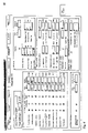
- FIG. 3 is a screen shot of the global parameter mask
- FIG. 4 is a screen shot of a segment parameter mask.
- a rotary coating system 31 comprises twelve processing stations 32 or twelve chambers.
- the chambers 32 double reactors are each provided with respectively two MW generators 33 .
- the segmentation takes place so that two chambers are always in the coating phase ( 17 , 18 , 19 , 20 ) for the adhesion promoter.
- Four chambers ( 9 , 10 , 11 , 12 , 13 , 14 , 15 , 16 ) are always in the coating phase for the barrier.
- the other segments ( 21 , 22 , 1 , 2 ) the bottles are transferred to the machine or leave the machine.
- pump functions are controlled ( 3 , 4 , 5 , 6 ).
- Said gas generator is supplied by a precursor storage container.
- FIG. 3 shows the adjustment of global recipe parameters; there comprise regulating speed and mass flow regulation.
- the descriptions are self-explanatory so that no further comment need be made on this with reference to FIG. 1 .
- FIG. 4 shows the control in a fifth segment which comprises the flooding segment ( 17 , 18 , 19 , 20 ) in relation to FIG. 2 .
- This segment begins at 275 degrees.
- the functions internal aeration and external aeration are activated and begin with a delay of 80 ms or 150 ms respectively and end after 25 degrees relative to the beginning of the segment. Flushing gas is then pumped in, this being initiated after a delay of 140 ms and also being initiated so that it covers the segments. Since this involves the end of the segment, the flushing is stopped at the latest when the bottle is ejected.
Landscapes
- Physics & Mathematics (AREA)
- General Physics & Mathematics (AREA)
- Engineering & Computer Science (AREA)
- Automation & Control Theory (AREA)
- Chemical Vapour Deposition (AREA)
- Details Of Rigid Or Semi-Rigid Containers (AREA)
- Spray Control Apparatus (AREA)
- Numerical Control (AREA)
- Coating Apparatus (AREA)
Abstract
Description
Claims (21)
Applications Claiming Priority (2)
| Application Number | Priority Date | Filing Date | Title |
|---|---|---|---|
| DE102005015063.2 | 2005-03-31 | ||
| DE102005015063A DE102005015063B4 (en) | 2005-03-31 | 2005-03-31 | Apparatus and method for the automatic generation of control instructions for rotary machines |
Publications (2)
| Publication Number | Publication Date |
|---|---|
| US20060224257A1 US20060224257A1 (en) | 2006-10-05 |
| US7433752B2 true US7433752B2 (en) | 2008-10-07 |
Family
ID=36972809
Family Applications (1)
| Application Number | Title | Priority Date | Filing Date |
|---|---|---|---|
| US11/391,172 Expired - Lifetime US7433752B2 (en) | 2005-03-31 | 2006-03-28 | Device and method for automatic generation of control instructions for rotary machines |
Country Status (4)
| Country | Link |
|---|---|
| US (1) | US7433752B2 (en) |
| JP (1) | JP4963853B2 (en) |
| DE (1) | DE102005015063B4 (en) |
| FR (1) | FR2883993A1 (en) |
Cited By (3)
| Publication number | Priority date | Publication date | Assignee | Title |
|---|---|---|---|---|
| CN101758615B (en) * | 2009-05-17 | 2012-02-15 | 柳州市精业机器有限公司 | Double-station reciprocating rotary type injection stretch blow hollow forming machine |
| US8386072B1 (en) * | 2009-04-20 | 2013-02-26 | Pneumatic Scale Corporation | Dual meter filler apparatus and method |
| US11307554B2 (en) | 2019-11-20 | 2022-04-19 | Younes Faraj | System and method for keyword-based PLC programming |
Families Citing this family (4)
| Publication number | Priority date | Publication date | Assignee | Title |
|---|---|---|---|---|
| DE102012204690A1 (en) | 2012-03-23 | 2013-09-26 | Krones Ag | Apparatus for plasma coating of product containers, such as bottles |
| CN103677570B (en) * | 2013-12-16 | 2017-01-04 | 中国电子科技集团公司第四十一研究所 | A kind of intelligent association input method of microwave measuring instrument software |
| CN108594667A (en) * | 2018-05-02 | 2018-09-28 | 芜湖乐锐思信息咨询有限公司 | Smart home control host with regulatory function |
| CN109352961A (en) * | 2018-10-23 | 2019-02-19 | 佛山美石机械有限公司 | A kind of rotation of bottle blowing machine takes a bottle manipulator |
Citations (6)
| Publication number | Priority date | Publication date | Assignee | Title |
|---|---|---|---|---|
| US5357450A (en) * | 1991-12-02 | 1994-10-18 | General Electric Company | Automated maintenance system for computer numerically controlled machines |
| DE19911294C1 (en) | 1999-03-13 | 2000-06-15 | Fette Wilhelm Gmbh | Adjustment device for press with circular rotors for manufacture of tablets has two-stage coarse and fine adjustment systems |
| DE10231345A1 (en) | 2002-03-18 | 2003-10-16 | Tetra Laval Holdings & Finance | Device for producing plastic containers by means of stretch blow molding and device for coating the inner walls of a plastic container |
| US20050092772A1 (en) * | 2003-10-30 | 2005-05-05 | Miller William A. | Automated cosmetics dispenser for point of sale cosmetics products |
| US7025559B2 (en) * | 2004-06-04 | 2006-04-11 | General Electric Company | Methods and systems for operating rotary machines |
| US20060099340A1 (en) * | 2002-05-24 | 2006-05-11 | Schott Ag | Device and method for treating workpieces |
Family Cites Families (2)
| Publication number | Priority date | Publication date | Assignee | Title |
|---|---|---|---|---|
| US5855681A (en) * | 1996-11-18 | 1999-01-05 | Applied Materials, Inc. | Ultra high throughput wafer vacuum processing system |
| JP4489853B2 (en) * | 1998-09-01 | 2010-06-23 | 株式会社日立国際電気 | Semiconductor manufacturing equipment |
-
2005
- 2005-03-31 DE DE102005015063A patent/DE102005015063B4/en not_active Revoked
-
2006
- 2006-03-28 JP JP2006086944A patent/JP4963853B2/en not_active Expired - Lifetime
- 2006-03-28 US US11/391,172 patent/US7433752B2/en not_active Expired - Lifetime
- 2006-03-31 FR FR0602811A patent/FR2883993A1/en not_active Withdrawn
Patent Citations (7)
| Publication number | Priority date | Publication date | Assignee | Title |
|---|---|---|---|---|
| US5357450A (en) * | 1991-12-02 | 1994-10-18 | General Electric Company | Automated maintenance system for computer numerically controlled machines |
| DE19911294C1 (en) | 1999-03-13 | 2000-06-15 | Fette Wilhelm Gmbh | Adjustment device for press with circular rotors for manufacture of tablets has two-stage coarse and fine adjustment systems |
| DE10231345A1 (en) | 2002-03-18 | 2003-10-16 | Tetra Laval Holdings & Finance | Device for producing plastic containers by means of stretch blow molding and device for coating the inner walls of a plastic container |
| US20060110483A1 (en) * | 2002-03-18 | 2006-05-25 | Volker Damerow | Device for the production of plastic containers by means of stretch blow moulding and device for coating the inner walls of a plastic container |
| US20060099340A1 (en) * | 2002-05-24 | 2006-05-11 | Schott Ag | Device and method for treating workpieces |
| US20050092772A1 (en) * | 2003-10-30 | 2005-05-05 | Miller William A. | Automated cosmetics dispenser for point of sale cosmetics products |
| US7025559B2 (en) * | 2004-06-04 | 2006-04-11 | General Electric Company | Methods and systems for operating rotary machines |
Cited By (3)
| Publication number | Priority date | Publication date | Assignee | Title |
|---|---|---|---|---|
| US8386072B1 (en) * | 2009-04-20 | 2013-02-26 | Pneumatic Scale Corporation | Dual meter filler apparatus and method |
| CN101758615B (en) * | 2009-05-17 | 2012-02-15 | 柳州市精业机器有限公司 | Double-station reciprocating rotary type injection stretch blow hollow forming machine |
| US11307554B2 (en) | 2019-11-20 | 2022-04-19 | Younes Faraj | System and method for keyword-based PLC programming |
Also Published As
| Publication number | Publication date |
|---|---|
| DE102005015063A1 (en) | 2006-10-12 |
| DE102005015063B4 (en) | 2008-05-15 |
| JP4963853B2 (en) | 2012-06-27 |
| FR2883993A1 (en) | 2006-10-06 |
| JP2006285988A (en) | 2006-10-19 |
| US20060224257A1 (en) | 2006-10-05 |
Similar Documents
| Publication | Publication Date | Title |
|---|---|---|
| JP5922713B2 (en) | How to perform batch processing | |
| KR100434025B1 (en) | Method for automatically generating part program for use in step-nc | |
| CN104155972B (en) | Mechanical engineering electronic controller parameter debugging method | |
| US7433752B2 (en) | Device and method for automatic generation of control instructions for rotary machines | |
| US20040193287A1 (en) | Method for offline-parametering of a field device of the process automation technology | |
| US20090326852A1 (en) | Method for Testing Device Descriptions for Field Devices of Automation Technology | |
| US20020049959A1 (en) | Industrial controller based on distributable technology objects | |
| JP2012510099A5 (en) | ||
| CN100430848C (en) | Programmable controller system based on foundation fieldbus high-speed Ethernet | |
| CN104063242A (en) | Method applicable to parameter upgrading in whole production process of inertial measurement unit | |
| US20210405611A1 (en) | Virtual computerized numerical control machine system and method | |
| US8667475B2 (en) | Computer-readable storage medium and program-converting method | |
| US10747211B2 (en) | Method for engineering a method- or process-engineering plant, function module and stored program control | |
| US20090182451A1 (en) | Method for controlling turning machining and nc machines suitable for turning machining | |
| JP7704866B2 (en) | Machine tool control device and machine tool control system | |
| CN105807718A (en) | Production machine with own functionality testing and method | |
| US5479354A (en) | Method for the computer-assisted control of a machine or process | |
| US20130218300A1 (en) | Method for operating an automation system | |
| US6584373B1 (en) | Method for controlling a CNC machine tool | |
| CN114489616A (en) | Industrial control upper computer motion control system and software editing method | |
| JP4564965B2 (en) | Method for generating an injection program | |
| CN108027602B (en) | Simulation method for simulating a real controller of an industrial process, facility or machine and simulation system for performing the simulation method | |
| CN120390911A (en) | Method for operating a production machine or a machine tool and a production machine or a machine tool | |
| Rooker et al. | Modeling flexible mechatronical based assembly systems through simulation support | |
| JP2004031671A (en) | System and method for treating substrate |
Legal Events
| Date | Code | Title | Description |
|---|---|---|---|
| AS | Assignment |
Owner name: SCHOTT AG, GERMANY Free format text: ASSIGNMENT OF ASSIGNORS INTEREST;ASSIGNORS:EIMANN, PETER;JOHANNES, PATRICK;EGGERT, HARTMUT;AND OTHERS;REEL/FRAME:017613/0666;SIGNING DATES FROM 20060416 TO 20060428 |
|
| STCF | Information on status: patent grant |
Free format text: PATENTED CASE |
|
| FPAY | Fee payment |
Year of fee payment: 4 |
|
| FPAY | Fee payment |
Year of fee payment: 8 |
|
| SULP | Surcharge for late payment |
Year of fee payment: 7 |
|
| AS | Assignment |
Owner name: KHS PLASMAX GMBH, GERMANY Free format text: ASSIGNMENT OF ASSIGNORS INTEREST;ASSIGNOR:SCHOTT AG;REEL/FRAME:043473/0033 Effective date: 20160512 |
|
| AS | Assignment |
Owner name: KHS CORPOPLAST GMBH, GERMANY Free format text: MERGER;ASSIGNOR:KHS PLASMAX GMBH;REEL/FRAME:043823/0388 Effective date: 20170602 |
|
| MAFP | Maintenance fee payment |
Free format text: PAYMENT OF MAINTENANCE FEE, 12TH YEAR, LARGE ENTITY (ORIGINAL EVENT CODE: M1553); ENTITY STATUS OF PATENT OWNER: LARGE ENTITY Year of fee payment: 12 |
|
| AS | Assignment |
Owner name: KHS GMBH, GERMANY Free format text: MERGER;ASSIGNOR:KHS CORPOPLAST GMBH;REEL/FRAME:060715/0640 Effective date: 20210119 |