US7422231B2 - Air-bag - Google Patents

Air-bag Download PDF

Info

Publication number
US7422231B2
US7422231B2 US10/518,334 US51833405A US7422231B2 US 7422231 B2 US7422231 B2 US 7422231B2 US 51833405 A US51833405 A US 51833405A US 7422231 B2 US7422231 B2 US 7422231B2
Authority
US
United States
Prior art keywords
air
bag
gas inlet
inlet throat
inflatable region
Prior art date
Legal status (The legal status is an assumption and is not a legal conclusion. Google has not performed a legal analysis and makes no representation as to the accuracy of the status listed.)
Expired - Fee Related, expires
Application number
US10/518,334
Other versions
US20060255571A1 (en
Inventor
Altay Kismir
Simon Valkenburg
Current Assignee (The listed assignees may be inaccurate. Google has not performed a legal analysis and makes no representation or warranty as to the accuracy of the list.)
Autoliv Development AB
Original Assignee
Autoliv Development AB
Priority date (The priority date is an assumption and is not a legal conclusion. Google has not performed a legal analysis and makes no representation as to the accuracy of the date listed.)
Filing date
Publication date
Application filed by Autoliv Development AB filed Critical Autoliv Development AB
Assigned to AUTOLIV DEVELOPMENT AB reassignment AUTOLIV DEVELOPMENT AB ASSIGNMENT OF ASSIGNORS INTEREST (SEE DOCUMENT FOR DETAILS). Assignors: VALKENBURG, SIMON, KISMIR, ALTAY
Publication of US20060255571A1 publication Critical patent/US20060255571A1/en
Application granted granted Critical
Publication of US7422231B2 publication Critical patent/US7422231B2/en
Adjusted expiration legal-status Critical
Expired - Fee Related legal-status Critical Current

Links

Images

Classifications

    • BPERFORMING OPERATIONS; TRANSPORTING
    • B60VEHICLES IN GENERAL
    • B60RVEHICLES, VEHICLE FITTINGS, OR VEHICLE PARTS, NOT OTHERWISE PROVIDED FOR
    • B60R21/00Arrangements or fittings on vehicles for protecting or preventing injuries to occupants or pedestrians in case of accidents or other traffic risks
    • B60R21/02Occupant safety arrangements or fittings, e.g. crash pads
    • B60R21/16Inflatable occupant restraints or confinements designed to inflate upon impact or impending impact, e.g. air bags
    • B60R21/23Inflatable members
    • B60R21/231Inflatable members characterised by their shape, construction or spatial configuration
    • B60R21/232Curtain-type airbags deploying mainly in a vertical direction from their top edge
    • BPERFORMING OPERATIONS; TRANSPORTING
    • B60VEHICLES IN GENERAL
    • B60RVEHICLES, VEHICLE FITTINGS, OR VEHICLE PARTS, NOT OTHERWISE PROVIDED FOR
    • B60R21/00Arrangements or fittings on vehicles for protecting or preventing injuries to occupants or pedestrians in case of accidents or other traffic risks
    • B60R21/02Occupant safety arrangements or fittings, e.g. crash pads
    • B60R21/16Inflatable occupant restraints or confinements designed to inflate upon impact or impending impact, e.g. air bags
    • B60R21/26Inflatable occupant restraints or confinements designed to inflate upon impact or impending impact, e.g. air bags characterised by the inflation fluid source or means to control inflation fluid flow
    • B60R21/261Inflatable occupant restraints or confinements designed to inflate upon impact or impending impact, e.g. air bags characterised by the inflation fluid source or means to control inflation fluid flow with means other than bag structure to diffuse or guide inflation fluid
    • B60R2021/2612Gas guiding means, e.g. ducts

Definitions

  • the present invention relates to an air-bag.
  • an air-bag which has a plurality of inflatable regions or chambers which are to be supplied with gas from a gas generator.
  • One example of such an air-bag is a so-called “inflatable curtain” which is adapted to be mounted in the roof line of the vehicle above the door openings of the vehicle, and which is also adapted, when an accident occurs, to be deployed to lie adjacent to the window openings formed in the door, thus forming a protective curtain located between the occupants of the vehicle and the side of the vehicle.
  • inflatable curtains are intended to provide protection to the occupants of the vehicle in the event of a side impact or roll-over situation.
  • Inflatable curtains must be inflated very quickly, necessitating a high gas flow rate into the bag. The forces generated by this very high gas flow rate may cause the bag to tear. Continued inflation may result in the tear propagating, therefore degrading the performance characteristic of the air-bag. Certain areas of the air-bag have been found to be more prone to tearing than others, and in certain air-bag designs it has been found that even adding extra stitching does not result in the avoidance of such tearing.
  • the invention seeks to provide an improved air-bag.
  • an air-bag comprising an inflatable element having an inflatable region and a gas inlet throat extending from the inflatable region, a gusset of excess fabric being present in the region proximate to the junction between the gas inlet throat and the inflatable region.
  • the inflatable region and the gas inlet throat each have at least two side edges, one side edge of the gas inlet throat being substantially aligned with one side of the inflatable region, the other side edge of the gas inlet throat being substantially perpendicular to another side edge of the inflatable region.
  • the gusset is located adjacent the junction of the other side edge of the gas inlet throat and another side edge of the inflatable region.
  • the gas inlet throat is sharply bent or cranked and extends from a point between the ends of one side edge of the inflatable region, one part of the throat being substantially parallel with one side edge.
  • the gusset is formed integrally with the air-bag.
  • the inflatable region has a gas flow passage formed within it, the gas flow passage defining a first axis, and at least part of the gas inlet throat configured to be connected to an inflator defines a second axis, the air-bag having a first and a second configuration, the axis of the gas flow passage and the axis of the gas inlet throat defining an oblique angle therebetween in the first configuration, the two axes being co-aligned or parallel and the gusset of excess fabric being present in the region proximate to the junction between the gas inlet throat and the inflatable region in the second configuration.
  • the inflatable region incorporates a plurality of cells defined by seams in the air-bag, the cells communicating with the gas flow passage.
  • straps extend from spaced apart points on the inflatable region, each strap having a free end adapted to be secured to a respective anchoring point formed on the interior of a vehicle.
  • the air-bag is formed from woven fabric.
  • the woven fabric has warp and weft yarns, the axis defined by the gas flow passage being aligned with either the warp yarns or the weft yarns of the woven fabric, and the axis defined by the gas inlet throat being inclined at the oblique angle relative to either the warp yarns or the weft yarns of the fabric.
  • the oblique angle is between 10 and 20 degrees.
  • the oblique angle is 15 degrees.
  • the invention further provides for method for processing an air-bag for mounting in a vehicle, the air-bag comprising an inflatable element having an inflatable region and a gas inlet throat extending from a side edge of the inflatable region, the inflatable region having a gas flow passage formed within it, the gas flow passage defining a first axis; said gas inlet throat having a part configured to an inflator, which part defines a second axis, the gas inlet throat initially extending from the inflatable region, the method comprising the step of re-positioning the gas inlet throat from a first condition in which the axis defined by the gas inlet throat is inclined relative to the axis defined by the gas flow passage to a second condition in which the axis defined by the gas inlet throat is aligned with the axis defined by the gas flow passage, thereby forming a gusset of excess material, the gusset being located adjacent the junction of the gas inlet throat and the side edge of the inflatable region.
  • the method further comprises the step of concertina-folding the inflatable region.
  • the concertina folds are parallel to the axis defined by the gas flow passage of the inflatable region.
  • the method further comprises the step of encasing the air-bag in a sleeve or housing.
  • the method further comprises the step of locating parts of the air-bag to extend through apertures formed in the sleeve or housing such that the parts protrude from the sleeve or housing.
  • the method further comprises the step of connecting the gas inlet throat to a gas generator.
  • FIG. 1 is a diagrammatic side view of a prior art air-bag of the inflatable curtain type connected to a gas generator and sensor arrangement,
  • FIG. 2 is a diagrammatic side view of a presently preferred embodiment of an air-bag of the invention
  • FIG. 3 is an enlarged diagrammatic side view of a region of the air-bag of FIG. 2 shown in the first stage of preparation for mounting in a vehicle,
  • FIG. 4 is a diagrammatic side view of the air-bag of FIG. 2 in the final stage of preparation for mounting in a vehicle connected to a gas generator and sensor arrangement,
  • FIG. 5 is a diagrammatic side view of a region of a further form of air-bag.
  • FIG. 6 is a diagrammatic side view, corresponding to FIG. 5 , showing the air-bag in a first stage of preparation for mounting in a vehicle.
  • the prior art air-bag 2 of FIG. 1 is formed from two superimposed layers of fabric, each layer of fabric having the same outer peripheral shape.
  • the two layers of fabric may be secured together to form seams by stitching.
  • the entire bag may be constructed using a one piece weaving technique, familiar to those skilled in the art, in which the seams are integrally woven into the bag.
  • the inflatable curtain has a substantially rectangular main inflatable region 4 , defined by four side edges: an upper side edge 6 , lower side edge 8 and two opposed side edges 10 and 12 .
  • the upper and lower side edges 6 , 8 are longer than the two opposed side edges 10 , 12 .
  • a plurality of mounting tabs 14 extend from the upper side edge 6 of the air-bag.
  • Each of the mounting tabs 14 has a hole 16 formed therethrough to facilitate the mounting of the air-bag in a vehicle.
  • the mounting tabs 14 are evenly spaced along the upper side edge 6 of the substantially rectangular main inflatable region of the air-bag.
  • a projecting portion 18 is formed at one end of the substantially rectangular main inflatable region 4 , and extends from an upper corner of the region 4 in a direction parallel to the upper side edge 6 of the air-bag and perpendicular to a side edge 12 of the air-bag.
  • the projecting portion 18 is formed from the fabric used to form the main inflatable region 4 and thus the air-bag is formed integrally.
  • the projecting portion 18 defines a substantially rectangular shaped gas inlet throat 20 formed between an upper side edge 21 and lower side edge 23 .
  • the upper side edge 21 and the lower side edge 23 of the gas inlet throat are each constituted by a respective seam 22 , 24 .
  • the gas inlet throat 20 is linear and defines a first axis.
  • One end 25 of the gas inlet throat 20 which is remote from the rectangular region of the air-bag is connected to a gas generator 26 .
  • This gas generator is connected to a collision and roll-over sensor 27 .
  • the other end of the gas inlet throat 20 communicates with a gas flow passage 28 formed in the interior of the rectangular main inflatable region 4 of the air-bag.
  • the gas flow passage 28 is generally linear and runs along the top of the air-bag adjacent to the upper side edge 6 .
  • the gas flow passage 28 defines a second axis.
  • the axis of the gas inlet throat 20 and the axis of the gas flow passage 28 are co-aligned.
  • a plurality of vertically extending seams 30 define a row of inflatable cells 32 , each cell having a substantially vertical axis which intersects the lower edge 8 of the rectangular region of the air-bag.
  • the top of each of the cells 32 communicates with the gas flow passage 28 . When inflated, these cells 32 adopt a substantially cylindrical profile.
  • a pair of straps 34 , 36 extend from two spaced apart points on the lower side edge 8 of the air-bag. Each strap has a free end which is adapted to be secured or mounted to a respective anchoring point formed on the interior of a vehicle in which the air-bag is to be mounted.
  • the senor 27 In the event that the vehicle in which the air-bag 2 is mounted is involved in a side-impact collision or a rollover, the sensor 27 generates a signal which is sent to the gas generator 26 , causing the gas generator to generate and discharge gas.
  • the gas flows through the gas inlet throat 20 and along the gas flow passage 28 and hence into the cells 32 , which are inflated.
  • the cells inflate, they adopt a substantially cylindrical profile, resulting in the lower edge of the bag 8 decreasing in length. This reduction in length creates a line of tension between the anchoring points to which the straps 34 , 36 are secured which acts to hold the bag in place.
  • the substantially vertical axes of the cells 32 intersect this line of tension.
  • tearing may occur in the throat region of this type of air-bag.
  • tearing has been found to occur in the region ‘A’ shown in FIG. 1 , that is, in the region between the lower side edge 23 of the gas inlet throat 20 and the side edge 12 of the air-bag from which the gas inlet throat 20 extends.
  • FIG. 2 a presently preferred embodiment of an air-bag according to the invention is illustrated in a first configuration.
  • the basic design of the air-bag is very similar to that of FIG. 1 .
  • like parts have been given like references and will not be re-described in detail.
  • the air-bag in the first configuration is flat and the gas inlet throat 20 is not co-aligned with the gas flow passage 28 , but is inclined upwardly above the upper side edge 6 of the air-bag.
  • the axes defined by the gas inlet throat 20 and the gas flow passage 28 are not co-aligned, but are at an oblique angle relative to each other.
  • An oblique (as opposed to a right) angle is formed in the area A between the lower side edge 23 of the gas inlet throat 20 and the side edge of the air-bag 12 .
  • the preferred angle between the axis of the gas inlet throat 20 and the axis of the gas flow passage 28 is in the range of 10 to 20 degrees, the most preferred angle being 15 degrees.
  • the upper, lower and opposed side edges 6 , 8 , 10 , and 12 of the rectangular region 4 of the air-bag, together with the seams 30 formed in the air-bag and the axis defined by the gas flow passage 20 align with either the warp or the weft yarns of the fabric (shown at region B) from which the bag is made, and are thus perpendicular to the other of either the warp or weft yarns.
  • the axis of the gas inlet throat 20 defines respective oblique angles relative to both the warp and weft yarns of the fabric, shown at region C.
  • the air-bag In processing the air-bag 2 of FIG. 2 for mounting in a vehicle, the air-bag is initially in the configuration as shown in and described with reference to FIG. 2 . Subsequently, the gas inlet throat 20 is re-positioned so that the axis of the gas inlet throat 20 and the axis of the gas flow passage 28 are co-aligned, so that the air-bag has a second configuration as shown in FIG. 3 . Correspondingly, a right angle is created between the lower side edge 23 of the gas inlet throat 20 and the side edge 12 of the rectangular main inflatable region of the air-bag.
  • the air-bag of FIG. 3 is configured to have substantially the same overall configuration as the air-bag of FIG. 1 , and it may readily be mounted in a vehicle in the same manner as the air bag shown in and described with reference to FIG. 1 .
  • a wrinkled region or gusset 38 of excess fabric is formed along the lower edge 23 of the gas inlet throat where it joins the rectangular main inflatable region 4 of the air-bag.
  • “Gussett” as used in this specification and the claims means a wrinkled region of excess fabric formed along a lower region of the gas inlet throat where it joins the rectangular main inflatable region of the airbag, thus permitting this region to expand upon inflation to cause an obliquely angled gas inlet throat.
  • the air-bag may be attached to a gas generator 40 which in turn may be connected to a collision and roll-over sensor 42 , as shown in FIG. 4 .
  • the air-bag may be folded in a concertina manner with folds parallel to the axis defined by the gas flow passage.
  • the folded air-bag is encased within a sleeve or a housing 44 .
  • a plurality of mounting tabs 14 extend through and protrude from apertures 46 (apertures 46 are schematic) formed in the upper side edge of the sleeve or housing, and the straps 34 , 36 extend from the air-bag and protrude through the ends of the sleeve or housing 44 .
  • the mounting tabs 14 may be mounted by the holes 16 therein to anchoring points within the roof line of a vehicle, and straps 34 and 36 may be secured to respective anchoring points within the vehicle, which are preferably on the A and C posts of the vehicle, or alternatively on the A and B posts of the vehicle.
  • the senor 42 triggers the gas generator 40 to generate gas which is subsequently passed through the gas inlet throat 20 and into the gas flow passage 28 of the air-bag.
  • the gas will flow initially into the gas flow passage 28 of the air-bag and subsequently into the cells 32 .
  • the air-bag inflates to occupy a position beneath the sleeve 44 or housing.
  • the individual cells 32 of the air-bag inflate, and the lower edge 8 of the air-bag decreases in length, creating a line of tension between the anchoring points to which the straps 34 , 36 are attached.
  • the wrinkled region or gusset 38 is not particularly susceptible to tearing.
  • the presence of this gusset 38 increases the ability of the fabric to elongate, thus distributing the load applied across a greater area of material and to a greater amount of warp and weft strands.
  • a buffer zone is provided by the gusset 38 which acts to absorb the force applied by gas on inflation of the air-bag and minimize the risk of tearing.
  • an angle or corner such as the angle or corner between the lower side edge 23 of the gas inlet throat 20 and the side edge 12 of the air-bag is intrinsically stronger if one of the elements defining the angle or corner is at an oblique angle to the warp or weft yarns.
  • FIGS. 5 and 6 illustrate an air-bag 50 of this general type.
  • the air-bag 50 has an upper side edge 51 provided with a plurality of spaced-apart mounting tabs 52 . Adjacent the upper edge 51 within the inflatable region of the air-bag, is a gas flow passage 53 which extends parallel with the upper edge 51 .
  • a plurality of cells 54 , 55 are defined within the inflatable region by dividing seams 56 , 57 , as in the embodiment described above.
  • a gas inlet throat 58 is provided which extends from the upper edge 51 of the air-bag 50 .
  • the throat is a cranked, i.e. sharply bent, throat of generally “L” form having two arms 59 , 60 .
  • the arm 60 defines an axis 61 and, in an initial condition of the air-bag, the arm 60 is inclined by an angle relative to the upper edge 51 of the air-bag and thus relative to the axis of the gas flow passage 53 .
  • the warp and weft yarns of the fabric are parallel and orthogonal to the upper edge and the axis of the gas flow passage 53 .
  • the angle made by the axis 61 of the arm 60 of the throat 58 is in the region of 10 to 30 degrees, the most preferred angle being 20 degrees. As can be seen at regions C, the axis 61 makes the same angle with regard to the warp and weft yarns.
  • the air-bag in processing the air-bag for mounting in a vehicle, the air-bag is initially in the configuration shown in and described with reference to FIG. 5 . Subsequently, the arm 60 of the gas inlet throat is re-positioned so that the axis 61 of the gas inlet throat is parallel with the axis of the upper edge 51 and thus the axis of the gas flow passage 53 , as shown in FIG. 6 . As a consequence of this re-positioning of the gas inlet throat, a wrinkled region or gusset 62 of excess fabric is created on that part of the gas inlet throat 58 which lies between the arm 60 and the upper edge 51 of the air-bag 50 .
  • the air-bag 50 is to be attached to a gas generator which is attached to the end of the arm 60 of the gas inlet throat 58 .
  • the mounting tabs 52 are used to secure the air-bag within the roof line of a vehicle.
  • the wrinkled region or gusset 62 is not particularly susceptible to tearing due to the presence of the excess fabric.

Landscapes

  • Engineering & Computer Science (AREA)
  • Mechanical Engineering (AREA)
  • Air Bags (AREA)
  • Packages (AREA)
  • Medical Preparation Storing Or Oral Administration Devices (AREA)

Abstract

An air-bag comprising an inflatable element having an inflatable region and a gas inlet throat extending from the inflatable region, a gusset of excess fabric being present in the region proximate to the junction between the gas inlet throat and the inflatable region.

Description

CROSS REFERENCE TO RELATED APPLICATION
This application claims priority to PCT/SE03/000975, filed Jun. 12, 2003, and GB 0214396.4, filed Jun. 21, 2002.
BACKGROUND OF THE INVENTION
The present invention relates to an air-bag.
It has been proposed to provide an air-bag which has a plurality of inflatable regions or chambers which are to be supplied with gas from a gas generator. One example of such an air-bag is a so-called “inflatable curtain” which is adapted to be mounted in the roof line of the vehicle above the door openings of the vehicle, and which is also adapted, when an accident occurs, to be deployed to lie adjacent to the window openings formed in the door, thus forming a protective curtain located between the occupants of the vehicle and the side of the vehicle. Such inflatable curtains are intended to provide protection to the occupants of the vehicle in the event of a side impact or roll-over situation.
Inflatable curtains must be inflated very quickly, necessitating a high gas flow rate into the bag. The forces generated by this very high gas flow rate may cause the bag to tear. Continued inflation may result in the tear propagating, therefore degrading the performance characteristic of the air-bag. Certain areas of the air-bag have been found to be more prone to tearing than others, and in certain air-bag designs it has been found that even adding extra stitching does not result in the avoidance of such tearing.
The invention seeks to provide an improved air-bag.
SUMMARY OF THE INVENTION
According to the present invention, there is provided an air-bag comprising an inflatable element having an inflatable region and a gas inlet throat extending from the inflatable region, a gusset of excess fabric being present in the region proximate to the junction between the gas inlet throat and the inflatable region.
Preferably, the inflatable region and the gas inlet throat each have at least two side edges, one side edge of the gas inlet throat being substantially aligned with one side of the inflatable region, the other side edge of the gas inlet throat being substantially perpendicular to another side edge of the inflatable region. The gusset is located adjacent the junction of the other side edge of the gas inlet throat and another side edge of the inflatable region.
Alternatively, the gas inlet throat is sharply bent or cranked and extends from a point between the ends of one side edge of the inflatable region, one part of the throat being substantially parallel with one side edge.
Conveniently, the gusset is formed integrally with the air-bag.
Advantageously, the inflatable region has a gas flow passage formed within it, the gas flow passage defining a first axis, and at least part of the gas inlet throat configured to be connected to an inflator defines a second axis, the air-bag having a first and a second configuration, the axis of the gas flow passage and the axis of the gas inlet throat defining an oblique angle therebetween in the first configuration, the two axes being co-aligned or parallel and the gusset of excess fabric being present in the region proximate to the junction between the gas inlet throat and the inflatable region in the second configuration.
Preferably, the inflatable region incorporates a plurality of cells defined by seams in the air-bag, the cells communicating with the gas flow passage.
Conveniently, straps extend from spaced apart points on the inflatable region, each strap having a free end adapted to be secured to a respective anchoring point formed on the interior of a vehicle.
Advantageously, the air-bag is formed from woven fabric.
Preferably, the woven fabric has warp and weft yarns, the axis defined by the gas flow passage being aligned with either the warp yarns or the weft yarns of the woven fabric, and the axis defined by the gas inlet throat being inclined at the oblique angle relative to either the warp yarns or the weft yarns of the fabric.
Conveniently, the oblique angle is between 10 and 20 degrees.
Advantageously, the oblique angle is 15 degrees.
The invention further provides for method for processing an air-bag for mounting in a vehicle, the air-bag comprising an inflatable element having an inflatable region and a gas inlet throat extending from a side edge of the inflatable region, the inflatable region having a gas flow passage formed within it, the gas flow passage defining a first axis; said gas inlet throat having a part configured to an inflator, which part defines a second axis, the gas inlet throat initially extending from the inflatable region, the method comprising the step of re-positioning the gas inlet throat from a first condition in which the axis defined by the gas inlet throat is inclined relative to the axis defined by the gas flow passage to a second condition in which the axis defined by the gas inlet throat is aligned with the axis defined by the gas flow passage, thereby forming a gusset of excess material, the gusset being located adjacent the junction of the gas inlet throat and the side edge of the inflatable region.
Preferably, the method further comprises the step of concertina-folding the inflatable region.
Conveniently, the concertina folds are parallel to the axis defined by the gas flow passage of the inflatable region.
Advantageously, the method further comprises the step of encasing the air-bag in a sleeve or housing.
Preferably, the method further comprises the step of locating parts of the air-bag to extend through apertures formed in the sleeve or housing such that the parts protrude from the sleeve or housing.
Conveniently, the method further comprises the step of connecting the gas inlet throat to a gas generator.
BRIEF DESCRIPTION OF THE DRAWINGS
In order that the invention may be more readily understood, and so that further features thereof may be appreciated, the invention will now be described, by way of example, with reference to the accompanying drawings in which:
FIG. 1 is a diagrammatic side view of a prior art air-bag of the inflatable curtain type connected to a gas generator and sensor arrangement,
FIG. 2 is a diagrammatic side view of a presently preferred embodiment of an air-bag of the invention,
FIG. 3 is an enlarged diagrammatic side view of a region of the air-bag of FIG. 2 shown in the first stage of preparation for mounting in a vehicle,
FIG. 4 is a diagrammatic side view of the air-bag of FIG. 2 in the final stage of preparation for mounting in a vehicle connected to a gas generator and sensor arrangement,
FIG. 5 is a diagrammatic side view of a region of a further form of air-bag, and
FIG. 6 is a diagrammatic side view, corresponding to FIG. 5, showing the air-bag in a first stage of preparation for mounting in a vehicle.
DETAILED DESCRIPTION OF THE INVENTION
The prior art air-bag 2 of FIG. 1 is formed from two superimposed layers of fabric, each layer of fabric having the same outer peripheral shape. The two layers of fabric may be secured together to form seams by stitching. Alternatively, the entire bag may be constructed using a one piece weaving technique, familiar to those skilled in the art, in which the seams are integrally woven into the bag.
The inflatable curtain has a substantially rectangular main inflatable region 4, defined by four side edges: an upper side edge 6, lower side edge 8 and two opposed side edges 10 and 12. The upper and lower side edges 6, 8 are longer than the two opposed side edges 10, 12.
A plurality of mounting tabs 14 extend from the upper side edge 6 of the air-bag. Each of the mounting tabs 14 has a hole 16 formed therethrough to facilitate the mounting of the air-bag in a vehicle. The mounting tabs 14 are evenly spaced along the upper side edge 6 of the substantially rectangular main inflatable region of the air-bag.
A projecting portion 18 is formed at one end of the substantially rectangular main inflatable region 4, and extends from an upper corner of the region 4 in a direction parallel to the upper side edge 6 of the air-bag and perpendicular to a side edge 12 of the air-bag. The projecting portion 18 is formed from the fabric used to form the main inflatable region 4 and thus the air-bag is formed integrally.
The projecting portion 18 defines a substantially rectangular shaped gas inlet throat 20 formed between an upper side edge 21 and lower side edge 23. The upper side edge 21 and the lower side edge 23 of the gas inlet throat are each constituted by a respective seam 22, 24. The gas inlet throat 20 is linear and defines a first axis. One end 25 of the gas inlet throat 20 which is remote from the rectangular region of the air-bag is connected to a gas generator 26. This gas generator is connected to a collision and roll-over sensor 27. The other end of the gas inlet throat 20 communicates with a gas flow passage 28 formed in the interior of the rectangular main inflatable region 4 of the air-bag. The gas flow passage 28 is generally linear and runs along the top of the air-bag adjacent to the upper side edge 6. The gas flow passage 28 defines a second axis. The axis of the gas inlet throat 20 and the axis of the gas flow passage 28 are co-aligned.
A plurality of vertically extending seams 30 define a row of inflatable cells 32, each cell having a substantially vertical axis which intersects the lower edge 8 of the rectangular region of the air-bag. The top of each of the cells 32 communicates with the gas flow passage 28. When inflated, these cells 32 adopt a substantially cylindrical profile.
A pair of straps 34, 36 extend from two spaced apart points on the lower side edge 8 of the air-bag. Each strap has a free end which is adapted to be secured or mounted to a respective anchoring point formed on the interior of a vehicle in which the air-bag is to be mounted.
In the event that the vehicle in which the air-bag 2 is mounted is involved in a side-impact collision or a rollover, the sensor 27 generates a signal which is sent to the gas generator 26, causing the gas generator to generate and discharge gas. The gas flows through the gas inlet throat 20 and along the gas flow passage 28 and hence into the cells 32, which are inflated.
As the cells inflate, they adopt a substantially cylindrical profile, resulting in the lower edge of the bag 8 decreasing in length. This reduction in length creates a line of tension between the anchoring points to which the straps 34, 36 are secured which acts to hold the bag in place. The substantially vertical axes of the cells 32 intersect this line of tension.
It has been found that tearing may occur in the throat region of this type of air-bag. In particular tearing has been found to occur in the region ‘A’ shown in FIG. 1, that is, in the region between the lower side edge 23 of the gas inlet throat 20 and the side edge 12 of the air-bag from which the gas inlet throat 20 extends.
Turning to FIG. 2, a presently preferred embodiment of an air-bag according to the invention is illustrated in a first configuration. The basic design of the air-bag is very similar to that of FIG. 1. Thus like parts have been given like references and will not be re-described in detail.
In the embodiment of FIG. 2 the air-bag in the first configuration is flat and the gas inlet throat 20 is not co-aligned with the gas flow passage 28, but is inclined upwardly above the upper side edge 6 of the air-bag.
The axes defined by the gas inlet throat 20 and the gas flow passage 28 are not co-aligned, but are at an oblique angle relative to each other. An oblique (as opposed to a right) angle is formed in the area A between the lower side edge 23 of the gas inlet throat 20 and the side edge of the air-bag 12. The preferred angle between the axis of the gas inlet throat 20 and the axis of the gas flow passage 28 is in the range of 10 to 20 degrees, the most preferred angle being 15 degrees.
The upper, lower and opposed side edges 6, 8, 10, and 12 of the rectangular region 4 of the air-bag, together with the seams 30 formed in the air-bag and the axis defined by the gas flow passage 20 align with either the warp or the weft yarns of the fabric (shown at region B) from which the bag is made, and are thus perpendicular to the other of either the warp or weft yarns.
The axis of the gas inlet throat 20 defines respective oblique angles relative to both the warp and weft yarns of the fabric, shown at region C.
In processing the air-bag 2 of FIG. 2 for mounting in a vehicle, the air-bag is initially in the configuration as shown in and described with reference to FIG. 2. Subsequently, the gas inlet throat 20 is re-positioned so that the axis of the gas inlet throat 20 and the axis of the gas flow passage 28 are co-aligned, so that the air-bag has a second configuration as shown in FIG. 3. Correspondingly, a right angle is created between the lower side edge 23 of the gas inlet throat 20 and the side edge 12 of the rectangular main inflatable region of the air-bag.
Thus, the air-bag of FIG. 3 is configured to have substantially the same overall configuration as the air-bag of FIG. 1, and it may readily be mounted in a vehicle in the same manner as the air bag shown in and described with reference to FIG. 1.
As a result of the re-positioning of the gas inlet throat 20, with its axis aligned with that of the gas flow passage 28, a wrinkled region or gusset 38 of excess fabric is formed along the lower edge 23 of the gas inlet throat where it joins the rectangular main inflatable region 4 of the air-bag. “Gussett” as used in this specification and the claims means a wrinkled region of excess fabric formed along a lower region of the gas inlet throat where it joins the rectangular main inflatable region of the airbag, thus permitting this region to expand upon inflation to cause an obliquely angled gas inlet throat.
The air-bag may be attached to a gas generator 40 which in turn may be connected to a collision and roll-over sensor 42, as shown in FIG. 4. The air-bag may be folded in a concertina manner with folds parallel to the axis defined by the gas flow passage. The folded air-bag is encased within a sleeve or a housing 44. A plurality of mounting tabs 14 extend through and protrude from apertures 46 (apertures 46 are schematic) formed in the upper side edge of the sleeve or housing, and the straps 34, 36 extend from the air-bag and protrude through the ends of the sleeve or housing 44.
The mounting tabs 14 may be mounted by the holes 16 therein to anchoring points within the roof line of a vehicle, and straps 34 and 36 may be secured to respective anchoring points within the vehicle, which are preferably on the A and C posts of the vehicle, or alternatively on the A and B posts of the vehicle.
In the event that the vehicle in which the air-bag is mounted is involved in a side-impact collision or a roll-over, the sensor 42 triggers the gas generator 40 to generate gas which is subsequently passed through the gas inlet throat 20 and into the gas flow passage 28 of the air-bag.
The gas will flow initially into the gas flow passage 28 of the air-bag and subsequently into the cells 32.
As the gas flows into the cells 32, the air-bag inflates to occupy a position beneath the sleeve 44 or housing. The individual cells 32 of the air-bag inflate, and the lower edge 8 of the air-bag decreases in length, creating a line of tension between the anchoring points to which the straps 34, 36 are attached.
It has been found that due to the excess fabric, the wrinkled region or gusset 38 is not particularly susceptible to tearing. The presence of this gusset 38 increases the ability of the fabric to elongate, thus distributing the load applied across a greater area of material and to a greater amount of warp and weft strands.
Furthermore, a buffer zone is provided by the gusset 38 which acts to absorb the force applied by gas on inflation of the air-bag and minimize the risk of tearing.
It is also believed that an angle or corner, such as the angle or corner between the lower side edge 23 of the gas inlet throat 20 and the side edge 12 of the air-bag is intrinsically stronger if one of the elements defining the angle or corner is at an oblique angle to the warp or weft yarns.
Whilst the invention has been described above with reference to an embodiment in which the gas inlet throat for the air-bag is substantially aligned with the gas flow passage within the air-bag, it has been proposed to provide air-bags of the general form as shown in FIGS. 1 to 3, with a gas inlet throat which is mounted on the upper edge of the inflatable region, typically at a substantially central position. Locating the gas inlet throat in such a position facilitates rapid inflation of the air-bag.
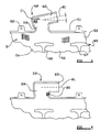
FIGS. 5 and 6 illustrate an air-bag 50 of this general type. The air-bag 50 has an upper side edge 51 provided with a plurality of spaced-apart mounting tabs 52. Adjacent the upper edge 51 within the inflatable region of the air-bag, is a gas flow passage 53 which extends parallel with the upper edge 51. A plurality of cells 54, 55 are defined within the inflatable region by dividing seams 56, 57, as in the embodiment described above.
A gas inlet throat 58 is provided which extends from the upper edge 51 of the air-bag 50. The throat is a cranked, i.e. sharply bent, throat of generally “L” form having two arms 59, 60. The arm 60 defines an axis 61 and, in an initial condition of the air-bag, the arm 60 is inclined by an angle relative to the upper edge 51 of the air-bag and thus relative to the axis of the gas flow passage 53. As can be seen in region B, the warp and weft yarns of the fabric are parallel and orthogonal to the upper edge and the axis of the gas flow passage 53. The angle made by the axis 61 of the arm 60 of the throat 58 is in the region of 10 to 30 degrees, the most preferred angle being 20 degrees. As can be seen at regions C, the axis 61 makes the same angle with regard to the warp and weft yarns.
It is to be appreciated that in processing the air-bag for mounting in a vehicle, the air-bag is initially in the configuration shown in and described with reference to FIG. 5. Subsequently, the arm 60 of the gas inlet throat is re-positioned so that the axis 61 of the gas inlet throat is parallel with the axis of the upper edge 51 and thus the axis of the gas flow passage 53, as shown in FIG. 6. As a consequence of this re-positioning of the gas inlet throat, a wrinkled region or gusset 62 of excess fabric is created on that part of the gas inlet throat 58 which lies between the arm 60 and the upper edge 51 of the air-bag 50.
Again the air-bag 50 is to be attached to a gas generator which is attached to the end of the arm 60 of the gas inlet throat 58. As in the previously-described embodiment, the mounting tabs 52 are used to secure the air-bag within the roof line of a vehicle. Also, it is to be understood that the wrinkled region or gusset 62 is not particularly susceptible to tearing due to the presence of the excess fabric.
While the above description constitutes the preferred embodiment of the present invention, it will be appreciated that the invention is susceptible to modification, variation and change without departing from the proper scope and fair meaning of the accompanying claims.

Claims (17)

1. An air-bag comprising an inflatable element having an inflatable region and a gas inlet throat joined to and extending from the inflatable region, the gas inlet throat configured for receiving gas to inflate the inflatable region, a gusset defined by a wrinkled region of excess fabric and being present in the region proximate to the junction between the gas inlet throat and the inflatable region, wherein the gusset elongates to absorb force that is applied by the gas to the inflatable element when the inflatable region is inflated.
2. An air-bag according to claim 1, wherein the inflatable region and the gas inlet throat each have at least a first and a second side edge, the first side edge of the gas inlet throat being substantially aligned with a first side of the inflatable region, the second side edge of the gas inlet throat being substantially perpendicular to a second side edge of the inflatable region, the gusset being located adjacent the junction of the second side edge of the gas inlet throat and the second side edge of the inflatable region.
3. An air-bag according to claim 1, wherein the gas inlet throat is cranked and extends from a point between opposed ends of a side edge of the inflatable region, one part of the throat being substantially parallel with the side edge.
4. An air-bag according to claim 1 wherein the gusset is formed integrally with the air-bag.
5. An air-bag according to claim 1 wherein the inflatable region has a gas flow passage formed within it, the gas flow passage defining a first axis, and at least part of the gas inlet throat configured to be connected to an inflator defines a second axis, the air-bag having a first and a second configuration, the axis of the gas flow passage and the axis of the gas inlet throat defining an oblique angle therebetween in the first configuration, the axes being co-aligned or parallel and the gusset being present in the region proximate to the junction between the gas inlet throat and the inflatable region in the second configuration.
6. An air-bag according to claim 5, wherein the inflatable region incorporates a plurality of cells defined by seams in the air-bag, the cells communicating with the gas flow passage.
7. An air-bag according to claim 6, wherein straps extend from spaced apart points on the inflatable region, each strap having a free end adapted to be secured to a respective anchoring point formed on the interior of a vehicle.
8. An air-bag according to claim 5 wherein the oblique angle is between 10 and 20 degrees.
9. An air-bag according to claim 8 wherein the oblique angle is 15 degrees.
10. An air-bag according to claim 1 wherein the air-bag is formed from woven fabric.
11. An air-bag according to claim 10 wherein the woven fabric has warp and weft yarns, and further wherein a gas flow passage formed within the inflatable region defines an axis which is aligned with either the warp yarns or the weft yarns of the woven fabric, and further wherein the axis defined by the gas inlet throat is inclined at an oblique angle relative to either the warp yarns or the weft yarns of the fabric.
12. A method for processing an air-bag for mounting in a vehicle, the air-bag comprising an inflatable element having an inflatable region and a gas inlet throat joined to and extending from a side edge of the inflatable region, the inflatable region having a gas flow passage formed within it, the gas flow passage defining a first axis; the gas inlet throat communicating with an inflator and defining a second axis, the gas inlet throat initially extending from the inflatable region, the method comprising the step of re-positioning the gas inlet throat from a first condition in which the axis defined by the gas inlet throat is inclined relative to the axis defined by the gas flow passage to a second condition in which the axis defined by the gas inlet throat is aligned with the axis defined by the gas flow passage, thereby forming a gusset of excess material, the gusset being located adjacent the junction of the gas inlet throat and the side edge of the inflatable region.
13. A method of processing an air-bag according to claim 12, further comprising the step of concertina-folding the inflatable region.
14. A method of processing an air-bag according to claim 13, wherein the concertina folds are parallel to the axis defined by the gas flow passage of the inflatable region.
15. A method of processing an air-bag according to claim 12 further comprising the step of encasing the air-bag in a sleeve or housing.
16. A method of processing an air-bag according to claim 15, further comprising the step of locating parts of the air-bag to extend through apertures formed in the sleeve or housing such that the parts protrude from the sleeve or housing.
17. A method of processing an air-bag according to claim 12 further comprising the step of connecting the gas inlet throat to a gas generator.
US10/518,334 2002-06-21 2003-06-12 Air-bag Expired - Fee Related US7422231B2 (en)

Applications Claiming Priority (3)

Application Number Priority Date Filing Date Title
GB0214396.4 2002-06-21
GB0214396A GB2389823A (en) 2002-06-21 2002-06-21 An airbag having a gusset of excess fabric between the gas inlet throat and the inflatable region of the bag
PCT/SE2003/000975 WO2004000609A1 (en) 2002-06-21 2003-06-12 An air-bag

Publications (2)

Publication Number Publication Date
US20060255571A1 US20060255571A1 (en) 2006-11-16
US7422231B2 true US7422231B2 (en) 2008-09-09

Family

ID=9939074

Family Applications (1)

Application Number Title Priority Date Filing Date
US10/518,334 Expired - Fee Related US7422231B2 (en) 2002-06-21 2003-06-12 Air-bag

Country Status (8)

Country Link
US (1) US7422231B2 (en)
EP (1) EP1536989B1 (en)
JP (1) JP4051372B2 (en)
AT (1) ATE398556T1 (en)
AU (1) AU2003245205A1 (en)
DE (1) DE60321687D1 (en)
GB (1) GB2389823A (en)
WO (1) WO2004000609A1 (en)

Cited By (4)

* Cited by examiner, † Cited by third party
Publication number Priority date Publication date Assignee Title
US20080197611A1 (en) * 2007-02-20 2008-08-21 Takata Corporation Curtain airbag and curtain airbag apparatus
US20080224457A1 (en) * 2005-03-02 2008-09-18 Autoliv Development Ab Tubular Gas Guide Element, Gas Generation and Feed Unit and Curtain Airbag Unit
US20100225098A1 (en) * 2007-11-20 2010-09-09 Takata-Petri Ag Airbag having a filling piece and airbag arrangement having an airbag and a gas generator
US8382151B2 (en) * 2009-10-28 2013-02-26 Key Safety Systems, Inc. Ejection countermeasures for curtain air bags

Families Citing this family (12)

* Cited by examiner, † Cited by third party
Publication number Priority date Publication date Assignee Title
GB2393692A (en) 2002-10-01 2004-04-07 Autoliv Dev Air bag with reinforced apertures in gas duct
GB2394921A (en) 2002-11-07 2004-05-12 Autoliv Dev A vehicle curtain type air bag rolled up when not in use
GB2399792A (en) 2003-03-24 2004-09-29 Autoliv Dev An air-bag mounting arrangement
EP1698522B1 (en) 2003-12-08 2009-05-06 Autoliv Development Ab Vehicle air bag device
US20050209539A1 (en) * 2004-03-19 2005-09-22 Mordechai Lev Body therapy apparatus
US20050212270A1 (en) * 2004-03-26 2005-09-29 Key Safety Systems, Inc. Unfolding assist mechanism for side curtain air bag
DE102004044525A1 (en) * 2004-09-15 2006-03-30 Autoliv Development Ab airbag
DE102005001598A1 (en) 2005-01-12 2006-07-20 Autoliv Development Ab Airbag and method for producing an airbag
DE102005054955A1 (en) * 2005-08-31 2007-04-26 Osram Opto Semiconductors Gmbh Light-emitting module, in particular for use in a projection optical device and optical projection device
KR20090126087A (en) * 2008-06-03 2009-12-08 현대자동차주식회사 Car airbag device
EP2876003A1 (en) * 2013-11-25 2015-05-27 Autoliv Development AB Airbag
US9663062B2 (en) * 2015-10-16 2017-05-30 Autoliv Asp, Inc. Airbags including internal tethers and methods of forming the same

Citations (38)

* Cited by examiner, † Cited by third party
Publication number Priority date Publication date Assignee Title
US5149130A (en) * 1991-05-28 1992-09-22 General Motors Corporation Liner for inflatable occupant restraint cushion
JPH06227344A (en) * 1993-02-08 1994-08-16 Toyota Motor Corp Bag body structure of side air bag unit
JPH0958392A (en) 1995-08-24 1997-03-04 Bridgestone Corp Air bag
WO1998026959A2 (en) 1996-12-17 1998-06-25 Petri Ag Airbag, especially lateral airbag
WO1999042333A1 (en) 1998-02-20 1999-08-26 Breed Automotive Technology, Inc. Side curtain airbag system
DE10021576A1 (en) 1999-05-27 2000-11-30 Takata Corp Protective cushion and protective device for the head area of a vehicle occupant
JP2000335356A (en) 1999-05-28 2000-12-05 Toyoda Gosei Co Ltd Airbag for head protection airbag device
US6199898B1 (en) 1998-08-20 2001-03-13 Takata Corporation Protective cushion for vehicle occupant's head
US6203058B1 (en) 2000-02-24 2001-03-20 Trw Inc. Inflatable curtain with two inflatable members
US6227561B1 (en) 1998-04-06 2001-05-08 Breed Automotive Technology, Inc. Roofliner for a motor vehicle
US6231073B1 (en) 1999-12-17 2001-05-15 Trw Vehicle Safety Systems Inc. Inflatable side curtain
US6273456B1 (en) 1998-08-20 2001-08-14 Trw Occupant Restraint Systems Gmbh & Co. Kg Gas bag
US20010019201A1 (en) 1998-08-20 2001-09-06 Yasushi Masuda Protective cushion for vehicle occupant's head
US6293581B1 (en) 1999-04-15 2001-09-25 Honda Giken Kogyo Kabushiki Kaisha Occupant restraint device
US6299199B1 (en) 1999-09-17 2001-10-09 Trw Vehicle Safety Systems Inc. Inflatable side curtain
US20010045729A1 (en) 1997-10-22 2001-11-29 Olaf Mueller Air bag device, production method of an air bag device, activation method of an air bag device and vehicle with an air bag device
US6336654B1 (en) 1999-12-09 2002-01-08 Trw Vehicle Safety Systems Inc. Inflatable side curtain
US20020014762A1 (en) 2000-03-17 2002-02-07 Trw Vehicle Safety Systems Inc. Inflatable side curtain
US20020020991A1 (en) 2000-07-31 2002-02-21 Toshinori Tanase Air bag in use for head protection air bag device
US20020036396A1 (en) 2000-09-27 2002-03-28 Trw Occupant Restraint Systems Gmbh & Co. Kg Side gas bag module
US20020056974A1 (en) 1999-05-12 2002-05-16 Thomas Webert Inflatable airbag module for an airbag unit
US6409211B1 (en) 2000-10-10 2002-06-25 Trw Vehicle Safety Systems Inc. Inflatable side curtain
US6428037B1 (en) 2001-04-20 2002-08-06 Trw Vehicle Safety Systems Inc. Inflatable curtain
US20020105173A1 (en) 2001-02-08 2002-08-08 Saderholm Davin G. Inflatable curtain cushion
US6431587B1 (en) 1999-11-02 2002-08-13 Trw Inc. Inflatable side curtain
EP1238865A2 (en) 2001-03-06 2002-09-11 Takata Corporation Automotive vehicle and head protection device for vehicle occupants
US20020125693A1 (en) 2001-03-07 2002-09-12 Alsup Therial Levell Hinging reinforced trim piece
US6450527B2 (en) * 2000-04-21 2002-09-17 Takata Corporation Protection bag and protection apparatus for protecting head of automobile passenger
US20020163167A1 (en) 2001-05-02 2002-11-07 Trw Vehicle Safety Systems Inc. Multi-layered inflatable curtain
US20020175502A1 (en) 2001-05-23 2002-11-28 Tesch Todd E. Tensioning assembly for curtain style inflatable air bag
US20020195804A1 (en) 2001-06-26 2002-12-26 Hess Travis B. Apparatus and method for airbag inflation gas distribution
WO2003018372A1 (en) 2001-08-22 2003-03-06 Autoliv Development Ab An air-bag
WO2003051679A1 (en) 2001-12-18 2003-06-26 Autoliv Development Ab An air-bag
WO2003051680A1 (en) 2001-12-18 2003-06-26 Autoliv Development Ab An air-bag
WO2003078214A1 (en) 2002-03-19 2003-09-25 Autoliv Development Ab An air-bag
US6655713B2 (en) * 2000-06-30 2003-12-02 Toyoda Gosei Co., Ltd. Air bag
US6793240B2 (en) * 2002-07-25 2004-09-21 Autoliv Asp, Inc. Expandable section for inflatable curtains
US6869099B2 (en) * 2001-02-20 2005-03-22 Nissan Motor Co., Ltd. Air bag apparatus for vehicle

Family Cites Families (2)

* Cited by examiner, † Cited by third party
Publication number Priority date Publication date Assignee Title
US6303114B1 (en) * 1998-03-05 2001-10-16 The Medical College Of Ohio IL-12 enhancement of immune responses to T-independent antigens
FR2835616B1 (en) * 2002-02-01 2005-02-11 Junior Instruments DEVICE FOR THE AUTOMATED ANALYSIS OF A LIQUID SAMPLE

Patent Citations (39)

* Cited by examiner, † Cited by third party
Publication number Priority date Publication date Assignee Title
US5149130A (en) * 1991-05-28 1992-09-22 General Motors Corporation Liner for inflatable occupant restraint cushion
JPH06227344A (en) * 1993-02-08 1994-08-16 Toyota Motor Corp Bag body structure of side air bag unit
JPH0958392A (en) 1995-08-24 1997-03-04 Bridgestone Corp Air bag
WO1998026959A2 (en) 1996-12-17 1998-06-25 Petri Ag Airbag, especially lateral airbag
US20010045729A1 (en) 1997-10-22 2001-11-29 Olaf Mueller Air bag device, production method of an air bag device, activation method of an air bag device and vehicle with an air bag device
WO1999042333A1 (en) 1998-02-20 1999-08-26 Breed Automotive Technology, Inc. Side curtain airbag system
US6073961A (en) 1998-02-20 2000-06-13 Breed Automotive Technology, Inc. Inflatable side airbag curtain module
US6227561B1 (en) 1998-04-06 2001-05-08 Breed Automotive Technology, Inc. Roofliner for a motor vehicle
US6199898B1 (en) 1998-08-20 2001-03-13 Takata Corporation Protective cushion for vehicle occupant's head
US6273456B1 (en) 1998-08-20 2001-08-14 Trw Occupant Restraint Systems Gmbh & Co. Kg Gas bag
US20010019201A1 (en) 1998-08-20 2001-09-06 Yasushi Masuda Protective cushion for vehicle occupant's head
US6293581B1 (en) 1999-04-15 2001-09-25 Honda Giken Kogyo Kabushiki Kaisha Occupant restraint device
US20020056974A1 (en) 1999-05-12 2002-05-16 Thomas Webert Inflatable airbag module for an airbag unit
DE10021576A1 (en) 1999-05-27 2000-11-30 Takata Corp Protective cushion and protective device for the head area of a vehicle occupant
JP2000335356A (en) 1999-05-28 2000-12-05 Toyoda Gosei Co Ltd Airbag for head protection airbag device
US6299199B1 (en) 1999-09-17 2001-10-09 Trw Vehicle Safety Systems Inc. Inflatable side curtain
US6431587B1 (en) 1999-11-02 2002-08-13 Trw Inc. Inflatable side curtain
US6336654B1 (en) 1999-12-09 2002-01-08 Trw Vehicle Safety Systems Inc. Inflatable side curtain
US6231073B1 (en) 1999-12-17 2001-05-15 Trw Vehicle Safety Systems Inc. Inflatable side curtain
US6203058B1 (en) 2000-02-24 2001-03-20 Trw Inc. Inflatable curtain with two inflatable members
US20020014762A1 (en) 2000-03-17 2002-02-07 Trw Vehicle Safety Systems Inc. Inflatable side curtain
US6450527B2 (en) * 2000-04-21 2002-09-17 Takata Corporation Protection bag and protection apparatus for protecting head of automobile passenger
US6655713B2 (en) * 2000-06-30 2003-12-02 Toyoda Gosei Co., Ltd. Air bag
US20020020991A1 (en) 2000-07-31 2002-02-21 Toshinori Tanase Air bag in use for head protection air bag device
US20020036396A1 (en) 2000-09-27 2002-03-28 Trw Occupant Restraint Systems Gmbh & Co. Kg Side gas bag module
US6409211B1 (en) 2000-10-10 2002-06-25 Trw Vehicle Safety Systems Inc. Inflatable side curtain
US20020105173A1 (en) 2001-02-08 2002-08-08 Saderholm Davin G. Inflatable curtain cushion
US6869099B2 (en) * 2001-02-20 2005-03-22 Nissan Motor Co., Ltd. Air bag apparatus for vehicle
EP1238865A2 (en) 2001-03-06 2002-09-11 Takata Corporation Automotive vehicle and head protection device for vehicle occupants
US20020125693A1 (en) 2001-03-07 2002-09-12 Alsup Therial Levell Hinging reinforced trim piece
US6428037B1 (en) 2001-04-20 2002-08-06 Trw Vehicle Safety Systems Inc. Inflatable curtain
US20020163167A1 (en) 2001-05-02 2002-11-07 Trw Vehicle Safety Systems Inc. Multi-layered inflatable curtain
US20020175502A1 (en) 2001-05-23 2002-11-28 Tesch Todd E. Tensioning assembly for curtain style inflatable air bag
US20020195804A1 (en) 2001-06-26 2002-12-26 Hess Travis B. Apparatus and method for airbag inflation gas distribution
WO2003018372A1 (en) 2001-08-22 2003-03-06 Autoliv Development Ab An air-bag
WO2003051679A1 (en) 2001-12-18 2003-06-26 Autoliv Development Ab An air-bag
WO2003051680A1 (en) 2001-12-18 2003-06-26 Autoliv Development Ab An air-bag
WO2003078214A1 (en) 2002-03-19 2003-09-25 Autoliv Development Ab An air-bag
US6793240B2 (en) * 2002-07-25 2004-09-21 Autoliv Asp, Inc. Expandable section for inflatable curtains

Non-Patent Citations (1)

* Cited by examiner, † Cited by third party
Title
American Heritage Dictionary, 2<SUP>nd </SUP>College Edition, c. 1982, p. 583. *

Cited By (6)

* Cited by examiner, † Cited by third party
Publication number Priority date Publication date Assignee Title
US20080224457A1 (en) * 2005-03-02 2008-09-18 Autoliv Development Ab Tubular Gas Guide Element, Gas Generation and Feed Unit and Curtain Airbag Unit
US7648162B2 (en) * 2005-03-02 2010-01-19 Autoliv Development Ab Tubular gas guide element, gas generation and feed unit and curtain airbag unit
US20080197611A1 (en) * 2007-02-20 2008-08-21 Takata Corporation Curtain airbag and curtain airbag apparatus
US20100225098A1 (en) * 2007-11-20 2010-09-09 Takata-Petri Ag Airbag having a filling piece and airbag arrangement having an airbag and a gas generator
US8342571B2 (en) * 2007-11-20 2013-01-01 Takata AG Airbag having a filling piece and airbag arrangement having an airbag and a gas generator
US8382151B2 (en) * 2009-10-28 2013-02-26 Key Safety Systems, Inc. Ejection countermeasures for curtain air bags

Also Published As

Publication number Publication date
EP1536989A1 (en) 2005-06-08
DE60321687D1 (en) 2008-07-31
GB2389823A (en) 2003-12-24
JP4051372B2 (en) 2008-02-20
GB0214396D0 (en) 2002-07-31
AU2003245205A1 (en) 2004-01-06
US20060255571A1 (en) 2006-11-16
WO2004000609A1 (en) 2003-12-31
JP2005529796A (en) 2005-10-06
ATE398556T1 (en) 2008-07-15
EP1536989B1 (en) 2008-06-18

Similar Documents

Publication Publication Date Title
US7159896B2 (en) Occupant restraint system
US7422231B2 (en) Air-bag
US6672612B2 (en) Airbag for a motor vehicle
US7828322B2 (en) Airbag device
US7213836B2 (en) Curtain air bag module
US9067563B2 (en) Head protection airbag apparatus
US20070001433A1 (en) Head-protecting airbag and head-protecting airbag device
EP1117566A1 (en) Roll-over airbag
US7422233B2 (en) Air-bag
KR100650145B1 (en) Airbag
US20040100077A1 (en) Airbag for head-protecting airbag device
US20070096443A1 (en) Airbag
EP1256491B1 (en) Head-protecting bag device for occupants in an automobile
US7963557B2 (en) Airbag for protecting a vehicle occupant
US7614643B2 (en) Inflatable curtain air-bag
US12097820B1 (en) Airbag with extendable member
US7063351B2 (en) Air-bag arrangement
GB2374053A (en) Air bag with tensioning means
WO2022215399A1 (en) Curtain airbag and curtain airbag device

Legal Events

Date Code Title Description
AS Assignment

Owner name: AUTOLIV DEVELOPMENT AB, SWEDEN

Free format text: ASSIGNMENT OF ASSIGNORS INTEREST;ASSIGNORS:KISMIR, ALTAY;VALKENBURG, SIMON;REEL/FRAME:018034/0181;SIGNING DATES FROM 20050908 TO 20050909

STCF Information on status: patent grant

Free format text: PATENTED CASE

FPAY Fee payment

Year of fee payment: 4

FPAY Fee payment

Year of fee payment: 8

FEPP Fee payment procedure

Free format text: MAINTENANCE FEE REMINDER MAILED (ORIGINAL EVENT CODE: REM.); ENTITY STATUS OF PATENT OWNER: LARGE ENTITY

LAPS Lapse for failure to pay maintenance fees

Free format text: PATENT EXPIRED FOR FAILURE TO PAY MAINTENANCE FEES (ORIGINAL EVENT CODE: EXP.); ENTITY STATUS OF PATENT OWNER: LARGE ENTITY

STCH Information on status: patent discontinuation

Free format text: PATENT EXPIRED DUE TO NONPAYMENT OF MAINTENANCE FEES UNDER 37 CFR 1.362

FP Lapsed due to failure to pay maintenance fee

Effective date: 20200909