US7418946B2 - Engine start control apparatus and method - Google Patents
Engine start control apparatus and method Download PDFInfo
- Publication number
- US7418946B2 US7418946B2 US11/880,878 US88087807A US7418946B2 US 7418946 B2 US7418946 B2 US 7418946B2 US 88087807 A US88087807 A US 88087807A US 7418946 B2 US7418946 B2 US 7418946B2
- Authority
- US
- United States
- Prior art keywords
- rotation speed
- engine
- intake
- fuel
- target
- Prior art date
- Legal status (The legal status is an assumption and is not a legal conclusion. Google has not performed a legal analysis and makes no representation as to the accuracy of the status listed.)
- Active
Links
- 238000000034 method Methods 0.000 title claims description 45
- 239000000446 fuel Substances 0.000 claims abstract description 290
- 238000002347 injection Methods 0.000 claims abstract description 93
- 239000007924 injection Substances 0.000 claims abstract description 93
- 239000003054 catalyst Substances 0.000 claims abstract description 63
- 238000002485 combustion reaction Methods 0.000 claims abstract description 55
- 230000001133 acceleration Effects 0.000 claims abstract description 19
- 238000012545 processing Methods 0.000 claims abstract description 19
- 230000004044 response Effects 0.000 claims abstract description 14
- 238000001514 detection method Methods 0.000 claims abstract description 4
- 238000012937 correction Methods 0.000 claims description 160
- 239000007858 starting material Substances 0.000 claims description 55
- 239000007789 gas Substances 0.000 claims description 18
- 230000000979 retarding effect Effects 0.000 claims description 14
- 230000008859 change Effects 0.000 claims description 9
- QVGXLLKOCUKJST-UHFFFAOYSA-N atomic oxygen Chemical compound [O] QVGXLLKOCUKJST-UHFFFAOYSA-N 0.000 claims 9
- 239000001301 oxygen Substances 0.000 claims 9
- 229910052760 oxygen Inorganic materials 0.000 claims 9
- MWUXSHHQAYIFBG-UHFFFAOYSA-N Nitric oxide Chemical compound O=[N] MWUXSHHQAYIFBG-UHFFFAOYSA-N 0.000 description 21
- 238000004880 explosion Methods 0.000 description 21
- 230000008569 process Effects 0.000 description 17
- 230000007423 decrease Effects 0.000 description 16
- 239000004215 Carbon black (E152) Substances 0.000 description 15
- 229930195733 hydrocarbon Natural products 0.000 description 15
- 150000002430 hydrocarbons Chemical class 0.000 description 15
- 101100409308 Neurospora crassa (strain ATCC 24698 / 74-OR23-1A / CBS 708.71 / DSM 1257 / FGSC 987) adv-1 gene Proteins 0.000 description 12
- XLYOFNOQVPJJNP-UHFFFAOYSA-N water Substances O XLYOFNOQVPJJNP-UHFFFAOYSA-N 0.000 description 12
- 230000000694 effects Effects 0.000 description 10
- 239000000203 mixture Substances 0.000 description 7
- 230000006835 compression Effects 0.000 description 5
- 238000007906 compression Methods 0.000 description 5
- 239000000498 cooling water Substances 0.000 description 5
- 230000007246 mechanism Effects 0.000 description 5
- 230000001052 transient effect Effects 0.000 description 5
- UGFAIRIUMAVXCW-UHFFFAOYSA-N Carbon monoxide Chemical compound [O+]#[C-] UGFAIRIUMAVXCW-UHFFFAOYSA-N 0.000 description 4
- 229910002091 carbon monoxide Inorganic materials 0.000 description 4
- 230000003247 decreasing effect Effects 0.000 description 4
- 230000003213 activating effect Effects 0.000 description 3
- 230000000052 comparative effect Effects 0.000 description 3
- 238000002474 experimental method Methods 0.000 description 3
- 230000006978 adaptation Effects 0.000 description 2
- 230000003044 adaptive effect Effects 0.000 description 2
- 230000008901 benefit Effects 0.000 description 2
- 238000010586 diagram Methods 0.000 description 2
- 238000011144 upstream manufacturing Methods 0.000 description 2
- 230000008016 vaporization Effects 0.000 description 2
- 238000010792 warming Methods 0.000 description 2
- 230000004913 activation Effects 0.000 description 1
- 230000005540 biological transmission Effects 0.000 description 1
- 238000004140 cleaning Methods 0.000 description 1
- 230000007547 defect Effects 0.000 description 1
- 239000003344 environmental pollutant Substances 0.000 description 1
- 238000010304 firing Methods 0.000 description 1
- 230000006870 function Effects 0.000 description 1
- 239000007788 liquid Substances 0.000 description 1
- 231100000719 pollutant Toxicity 0.000 description 1
- 230000009467 reduction Effects 0.000 description 1
- 230000035939 shock Effects 0.000 description 1
- 239000000243 solution Substances 0.000 description 1
Images


Classifications
-
- F—MECHANICAL ENGINEERING; LIGHTING; HEATING; WEAPONS; BLASTING
- F02—COMBUSTION ENGINES; HOT-GAS OR COMBUSTION-PRODUCT ENGINE PLANTS
- F02P—IGNITION, OTHER THAN COMPRESSION IGNITION, FOR INTERNAL-COMBUSTION ENGINES; TESTING OF IGNITION TIMING IN COMPRESSION-IGNITION ENGINES
- F02P5/00—Advancing or retarding ignition; Control therefor
- F02P5/04—Advancing or retarding ignition; Control therefor automatically, as a function of the working conditions of the engine or vehicle or of the atmospheric conditions
- F02P5/145—Advancing or retarding ignition; Control therefor automatically, as a function of the working conditions of the engine or vehicle or of the atmospheric conditions using electrical means
- F02P5/15—Digital data processing
- F02P5/1502—Digital data processing using one central computing unit
- F02P5/1508—Digital data processing using one central computing unit with particular means during idling
-
- F—MECHANICAL ENGINEERING; LIGHTING; HEATING; WEAPONS; BLASTING
- F02—COMBUSTION ENGINES; HOT-GAS OR COMBUSTION-PRODUCT ENGINE PLANTS
- F02D—CONTROLLING COMBUSTION ENGINES
- F02D41/00—Electrical control of supply of combustible mixture or its constituents
- F02D41/0002—Controlling intake air
-
- F—MECHANICAL ENGINEERING; LIGHTING; HEATING; WEAPONS; BLASTING
- F02—COMBUSTION ENGINES; HOT-GAS OR COMBUSTION-PRODUCT ENGINE PLANTS
- F02D—CONTROLLING COMBUSTION ENGINES
- F02D41/00—Electrical control of supply of combustible mixture or its constituents
- F02D41/02—Circuit arrangements for generating control signals
- F02D41/04—Introducing corrections for particular operating conditions
- F02D41/06—Introducing corrections for particular operating conditions for engine starting or warming up
-
- F—MECHANICAL ENGINEERING; LIGHTING; HEATING; WEAPONS; BLASTING
- F02—COMBUSTION ENGINES; HOT-GAS OR COMBUSTION-PRODUCT ENGINE PLANTS
- F02D—CONTROLLING COMBUSTION ENGINES
- F02D41/00—Electrical control of supply of combustible mixture or its constituents
- F02D41/02—Circuit arrangements for generating control signals
- F02D41/04—Introducing corrections for particular operating conditions
- F02D41/08—Introducing corrections for particular operating conditions for idling
-
- F—MECHANICAL ENGINEERING; LIGHTING; HEATING; WEAPONS; BLASTING
- F02—COMBUSTION ENGINES; HOT-GAS OR COMBUSTION-PRODUCT ENGINE PLANTS
- F02D—CONTROLLING COMBUSTION ENGINES
- F02D11/00—Arrangements for, or adaptations to, non-automatic engine control initiation means, e.g. operator initiated
- F02D11/06—Arrangements for, or adaptations to, non-automatic engine control initiation means, e.g. operator initiated characterised by non-mechanical control linkages, e.g. fluid control linkages or by control linkages with power drive or assistance
- F02D11/10—Arrangements for, or adaptations to, non-automatic engine control initiation means, e.g. operator initiated characterised by non-mechanical control linkages, e.g. fluid control linkages or by control linkages with power drive or assistance of the electric type
- F02D2011/101—Arrangements for, or adaptations to, non-automatic engine control initiation means, e.g. operator initiated characterised by non-mechanical control linkages, e.g. fluid control linkages or by control linkages with power drive or assistance of the electric type characterised by the means for actuating the throttles
- F02D2011/102—Arrangements for, or adaptations to, non-automatic engine control initiation means, e.g. operator initiated characterised by non-mechanical control linkages, e.g. fluid control linkages or by control linkages with power drive or assistance of the electric type characterised by the means for actuating the throttles at least one throttle being moved only by an electric actuator
-
- F—MECHANICAL ENGINEERING; LIGHTING; HEATING; WEAPONS; BLASTING
- F02—COMBUSTION ENGINES; HOT-GAS OR COMBUSTION-PRODUCT ENGINE PLANTS
- F02D—CONTROLLING COMBUSTION ENGINES
- F02D31/00—Use of speed-sensing governors to control combustion engines, not otherwise provided for
- F02D31/001—Electric control of rotation speed
-
- F—MECHANICAL ENGINEERING; LIGHTING; HEATING; WEAPONS; BLASTING
- F02—COMBUSTION ENGINES; HOT-GAS OR COMBUSTION-PRODUCT ENGINE PLANTS
- F02D—CONTROLLING COMBUSTION ENGINES
- F02D37/00—Non-electrical conjoint control of two or more functions of engines, not otherwise provided for
- F02D37/02—Non-electrical conjoint control of two or more functions of engines, not otherwise provided for one of the functions being ignition
-
- F—MECHANICAL ENGINEERING; LIGHTING; HEATING; WEAPONS; BLASTING
- F02—COMBUSTION ENGINES; HOT-GAS OR COMBUSTION-PRODUCT ENGINE PLANTS
- F02D—CONTROLLING COMBUSTION ENGINES
- F02D41/00—Electrical control of supply of combustible mixture or its constituents
- F02D41/02—Circuit arrangements for generating control signals
- F02D41/14—Introducing closed-loop corrections
- F02D41/1438—Introducing closed-loop corrections using means for determining characteristics of the combustion gases; Sensors therefor
- F02D41/1444—Introducing closed-loop corrections using means for determining characteristics of the combustion gases; Sensors therefor characterised by the characteristics of the combustion gases
- F02D41/1454—Introducing closed-loop corrections using means for determining characteristics of the combustion gases; Sensors therefor characterised by the characteristics of the combustion gases the characteristics being an oxygen content or concentration or the air-fuel ratio
-
- F—MECHANICAL ENGINEERING; LIGHTING; HEATING; WEAPONS; BLASTING
- F02—COMBUSTION ENGINES; HOT-GAS OR COMBUSTION-PRODUCT ENGINE PLANTS
- F02D—CONTROLLING COMBUSTION ENGINES
- F02D41/00—Electrical control of supply of combustible mixture or its constituents
- F02D41/30—Controlling fuel injection
- F02D41/32—Controlling fuel injection of the low pressure type
- F02D41/34—Controlling fuel injection of the low pressure type with means for controlling injection timing or duration
-
- F—MECHANICAL ENGINEERING; LIGHTING; HEATING; WEAPONS; BLASTING
- F02—COMBUSTION ENGINES; HOT-GAS OR COMBUSTION-PRODUCT ENGINE PLANTS
- F02P—IGNITION, OTHER THAN COMPRESSION IGNITION, FOR INTERNAL-COMBUSTION ENGINES; TESTING OF IGNITION TIMING IN COMPRESSION-IGNITION ENGINES
- F02P3/00—Other installations
- F02P3/02—Other installations having inductive energy storage, e.g. arrangements of induction coils
- F02P3/04—Layout of circuits
- F02P3/0407—Opening or closing the primary coil circuit with electronic switching means
- F02P3/0414—Opening or closing the primary coil circuit with electronic switching means using digital techniques
-
- F—MECHANICAL ENGINEERING; LIGHTING; HEATING; WEAPONS; BLASTING
- F02—COMBUSTION ENGINES; HOT-GAS OR COMBUSTION-PRODUCT ENGINE PLANTS
- F02P—IGNITION, OTHER THAN COMPRESSION IGNITION, FOR INTERNAL-COMBUSTION ENGINES; TESTING OF IGNITION TIMING IN COMPRESSION-IGNITION ENGINES
- F02P5/00—Advancing or retarding ignition; Control therefor
- F02P5/04—Advancing or retarding ignition; Control therefor automatically, as a function of the working conditions of the engine or vehicle or of the atmospheric conditions
- F02P5/145—Advancing or retarding ignition; Control therefor automatically, as a function of the working conditions of the engine or vehicle or of the atmospheric conditions using electrical means
- F02P5/15—Digital data processing
- F02P5/1502—Digital data processing using one central computing unit
- F02P5/1506—Digital data processing using one central computing unit with particular means during starting
-
- Y—GENERAL TAGGING OF NEW TECHNOLOGICAL DEVELOPMENTS; GENERAL TAGGING OF CROSS-SECTIONAL TECHNOLOGIES SPANNING OVER SEVERAL SECTIONS OF THE IPC; TECHNICAL SUBJECTS COVERED BY FORMER USPC CROSS-REFERENCE ART COLLECTIONS [XRACs] AND DIGESTS
- Y02—TECHNOLOGIES OR APPLICATIONS FOR MITIGATION OR ADAPTATION AGAINST CLIMATE CHANGE
- Y02T—CLIMATE CHANGE MITIGATION TECHNOLOGIES RELATED TO TRANSPORTATION
- Y02T10/00—Road transport of goods or passengers
- Y02T10/10—Internal combustion engine [ICE] based vehicles
- Y02T10/40—Engine management systems
Definitions
- the present invention relates to an apparatus and method for controlling starting of an engine.
- a catalyst In a cold start of the engine, meaning that the engine and other components are not still warm from previous use, a catalyst is in an inactive state since its temperature is low and is incapable of purifying an exhaust gas. In this situation, it is important to activate the catalyst in order for the catalyst to begin to purify the exhaust gas.
- JP-A No. 8-232645 discloses a technique for activating the catalyst after the engine is started.
- an ignition timing is set at a start ignition timing until the engine is started by cranking and the engine fires. After the engine fires, the ignition timing is quickly retarded to a predetermined ignition timing after the compression top dead point, whereby the temperature of an exhaust gas is raised to quickly activate the catalyst. Further, an idling control valve is opened wide before the ignition timing retardation to thereby increase the amount of intake air, and after the ignition timing retardation, the amount of the intake air is further increased to smoothly and quickly fire the engine.
- JP-A-8-232645 causes the engine to smoothly and quickly fire, but the engine rotation speed exceeds a target idling rotation speed. This reduces the fuel economy because more fuel is consumed at the higher engine rotation speed.
- an engine start control apparatus includes an intake air amount control device for controlling an amount of air supplied to a combustion chamber, a fuel supply device for injecting fuel to be fed into the combustion chamber, and an igniting device for igniting the fuel.
- the engine start control apparatus further includes an engine operation state detecting unit for detecting an operation state of the engine, an ignition timing retard angle processing unit for operating the igniting device configured to retard an ignition timing from a start ignition timing to an ignition timing for catalyst warming-up acceleration in response to detection that the engine operation state has shifted to an idling operation state, an intake control device operation unit for operating an intake control device so as to supply such an amount of intake air as to keep the idling operation state when the engine operation state has shifted to the idling operation state, and an injection fuel amount increasing unit for increasing an amount of fuel injected into a cylinder to be shifted to a combustion stroke so as to be combusted in the combustion stroke when the engine operation state has shifted to the idling operation state.
- an engine operation state detecting unit for detecting an operation state of the engine
- an ignition timing retard angle processing unit for operating the igniting device configured to retard an ignition timing from a start ignition timing to an ignition timing for catalyst warming-up acceleration in response to detection that the engine operation
- an engine start control method includes retarding an ignition timing when an engine rotation speed at start of the engine reaches a target idling rotation speed, opening an intake throttle before the retarding of the ignition timing by a response delay period from when an intake throttle opens until air reaches a combustion chamber of the engine, and increasing an amount of fuel injected into a cylinder expected to be in a combustion stroke when the start engine rotation speed reaches the target idling rotation speed, and in the exhaust stroke immediately before the start engine rotation speed reaches the target idling rotation speed.
- the engine rotation speed swiftly settles down to the target rotation speed at the time of idling.
- FIG. 1 is a diagram schematically showing an arrangement of an engine start control apparatus according to a first embodiment of the present invention.
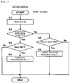
- FIG. 2 is a flow chart for setting a complete explosion flag and a target-rotation reaching flag in the first embodiment.
- FIG. 3 is a flow chart for calculating an ignition timing command value and a throttle-valve target opening-degree in the first embodiment.
- FIG. 4 is a flow chart showing a fuel-increase control logic.
- FIG. 5 is a flow chart showing a calculation routine for calculating an after-start fuel-increase correction coefficient KAS in the first embodiment.
- FIG. 6 is a flow chart for calculating a fuel injection pulse width Ti.
- FIG. 7 is a timing chart showing operations of the engine start control apparatus according to the first embodiment.
- FIG. 8 is a timing chart useful in explaining the effects of the engine start control apparatus of the first embodiment.
- FIG. 9 is a timing chart showing operations of an engine start control apparatus according to a second embodiment of the present invention.
- FIG. 10 is a timing chart showing operations of an engine start control apparatus according to a third embodiment of the present invention.
- FIG. 11 is a timing chart showing operations of an engine start control apparatus according to a fourth embodiment of the present invention.
- FIG. 12 is a timing chart showing operations of an engine start control apparatus according to a fifth embodiment of the present invention.
- FIG. 13 is a timing chart showing operations of an engine start control apparatus according to a sixth embodiment of the present invention.
- FIG. 14 is a flow chart for setting a complete explosion flag and a target-rotation reaching flag in the sixth embodiment.
- FIG. 15 is a timing chart showing operations of the engine start control apparatus according to the sixth embodiment.
- FIG. 16 is a flow chart showing a calculation routine for calculating an after-start fuel-increase correction coefficient KAS in the sixth embodiment.
- FIG. 17 is a graph diagrammatically showing a fuel correction quantity in the sixth embodiment.
- FIG. 18 is a timing chart showing operations of an engine start control apparatus according to a seventh embodiment of the present invention.
- FIG. 19 is a flow chart for calculating an ignition timing command value and a throttle valve target opening-degree in the seventh embodiment.
- FIG. 20 is a graph diagrammatically showing an ignition timing correction quantity in the seventh embodiment.
- FIG. 21 is a timing chart showing operations of engine start control apparatuses according to eighth and ninth embodiments of the present invention.
- FIG. 22 is a flow chart showing calculation routines for calculating an after-start fuel-increase correction coefficient KAS, common to both the eighth and ninth embodiments.
- FIG. 23 is a flow chart for calculating an ignition timing command value and a throttle valve target opening-degree in the ninth embodiment.
- FIG. 24 is a flow chart for explaining how to set a timer-2 value in the eighth and ninth embodiments.
- FIG. 25 is a timing chart comparatively showing operations of the engine start control apparatuses of the sixth and ninth to thirteenth embodiments of the invention.
- embodiments of the present invention relate to an engine start control apparatus and method which, in the cold start situation, swiftly shifts an engine operation state to an idling operation state after the complete ignition while accelerating the warming-up of the engine, and after the idling operation state is set up, sets up an operation state providing a stable air fuel ratio.
- FIG. 1 is a diagram schematically showing an arrangement of an engine start control apparatus according to a first embodiment of the present invention.
- An intake throttle device 51 as intake control means and a fuel injection valve 52 as fuel supply means are installed in an intake air passage 2 of an engine 1 , including an intake air collector 21 .
- the intake throttle device 51 includes an intake throttle 51 a and a throttle motor 51 b .
- a controller 7 as control means determines a target torque in accordance with a signal from an accelerator position sensor 67 , determines a target amount of air to attain the target torque, and controls a degree of opening of the intake throttle 51 a with the aid of the throttle motor 51 b so as to obtain the target air amount.
- the controller 7 determines a target air amount to attain the target torque and controls a degree of opening of the intake throttle 51 a with the aid of the throttle motor 51 b so as to obtain the target air amount.
- the intake throttle device 51 is not mechanically connected to the acceleration pedal 35 , and the throttle motor 51 b drives the intake throttle 51 a.
- An exhaust passage 3 is provided with a manifold catalyst 31 and an underfloor catalyst 32 .
- the manifold catalyst 31 and the underfloor catalyst 32 are each a three-way catalyst capable of simultaneously removing hydrocarbon (HC), carbon monoxide (CO) and nitrogen oxide (NOx) when the air fuel ratio of the exhaust gas is within a narrow range with respect to the theoretical air fuel ratio.
- the controller 7 determines a basic fuel injection amount of the fuel from the fuel injection valve 52 on the basis of operation conditions, and controls the air fuel ratio according to a signal from a O 2 sensor 64 located upstream of the manifold catalyst 31 in a feedback manner.
- the engine 1 includes a variable valve event and lift control system (referred to as “VEL mechanism”) 41 and a valve timing control (referred to as “VTC mechanism”) 42 .
- the VEL mechanism 41 is constructed with a multinodular-link mechanism to continuously vary a lift quantity and an operation angle of an intake valve 15 .
- the VTC mechanism 42 continuously varies a rotation phase difference between a crank shaft 14 and an intake-valve cam shaft 41 a to advance and retard a valve timing of the intake valve 15 .
- the amount of air is controlled by the intake throttle Sla and is stored in the intake air collector 21 .
- the air is introduced into respective cylinders 11 through an intake manifold 22 .
- the fuel is intermittently injected from the fuel injection valves 52 located at intake ports 23 of the cylinders to the intake ports 23 at predetermined timings.
- the controller 7 calculates an amount of fuel fed to the fuel injection valve 52 by using an intake air flow rate detected by an air flow meter 61 (air flow-rate detecting means) and an engine rotation speed calculated by using a signal from crank angle sensors ( 33 , 34 ).
- the injected fuel is mixed with the intake air to form an air-fuel mixture, which is confined in each cylinder 11 when the intake valve 15 is closed, compressed through the lifting of a piston 13 , and ignited with an ignition plug 17 to be combusted.
- a gas pressure generated by the combustion presses down the piston 13 .
- the reciprocal motion of the piston 13 is converted into a rotary motion of the crank shaft 14 .
- Gas (exhaust gas) after the combustion is exhausted to the exhaust passage 3 when an exhaust valve 16 is opened.
- the first catalyst 31 (start-up catalyst) is installed at the manifold aggregate of the exhaust passage 3
- the second catalyst 32 is positioned at the underfloor of the vehicle.
- Those two catalysts 31 and 32 are each a three-way catalyst.
- the three-way catalyst is capable of simultaneously removing HC, CO, and NOx when the air fuel ratio of the exhaust gas is within a narrow range with respect to the theoretical air fuel ratio.
- the controller 7 which receives a signal indicative of an intake air amount output from the air flow meter 61 and a signal from a crank angle sensor 62 (position sensor 33 and phase sensor 34 ), determines the basic fuel injection amount of the fuel from the fuel injection valve 52 according to those signals, and controls the air fuel ratio according to a signal from a O 2 sensor 64 located upstream of the manifold catalyst 31 in a feedback manner.
- the controller swiftly increases the temperature of the O 2 sensor 64 immediately after the start of the engine. Upon receipt of a signal from the O 2 sensor 64 , the controller performs the feedback control of the air fuel ratio at the timing of activating the O 2 sensor 64 .
- the catalysts 31 and 32 may be used in any other suitable way.
- the engine may be operated at a lean air fuel ratio, rather than the theoretical air fuel ratio.
- an NOx trap catalyst may be used for the second catalyst 32 in order to absorb NOx, which is generated in greater amounts during the lean operation of the engine.
- the NOx trap catalyst may have a three-way catalyst function.
- the controller 7 contains a microcomputer including a central processing unit (CPU), a read only memory (ROM), a random access memory (RAM), and an input/output interface (I/O interface).
- An engine controller 50 may contain a plurality of microcomputers.
- the ignition timing is set at a start ignition timing until the engine is completely ignited by the cranking and the engine fires. After the engine fires, the ignition timing is quickly retarded to a predetermined ignition timing following the compression top dead point, whereby the temperature of the exhaust gas is raised to quickly activate the catalyst. Further, the idling control valve is opened wide before the ignition timing retardation to thereby increase the amount of intake air, and after the ignition timing retardation, the intake air amount is further increased to smoothly and quickly ignite the engine. In the prior art, the engine smoothly and quickly fires, but the engine speed reaches then exceeds the target idling rotation speed. Accordingly, the fuel is wastefully consumed, which reduces the fuel economy.
- a preferable engine operation state for example, is such that when an engine rotation speed is detected, the engine rotation speed swiftly settles down to the target idling rotation speed without excessively exceeding the target idling rotation speed thereafter.
- the ignition timing is quickly retarded from the start ignition timing to a predetermined ignition timing after the compression top dead point when the engine rotation speed reaches the target idling rotation speed.
- the intake throttle is opened before the engine rotation speed reaches the target idling rotation speed, allowing for a response delay from the opening of the intake throttle until the intake air arrives at the combustion chamber.
- the engine rotation speed swiftly settles down to the target idling rotation speed without exceeding the target idling rotation speed, and is kept at the target idling rotation speed.
- the engine rotation speed settles down to the target idling rotation speed and is kept at the target idling rotation speed, but the air fuel ratio exceeds the stable combustion limit and becomes lean. If the air fuel ratio is within a narrow range, called a window, which extends with respect to the theoretical air fuel ratio, the three-way catalyst having undergone the warming-up operation is capable of simultaneously removing HC, CO, and NOx. If the air fuel ratio is too lean and outside the window, the cleaning performance of the catalyst degrades and the amount of exhausted HC increases.
- Embodiments of the present invention increase the amount of fuel injected at a proper timing so as to prevent the air fuel ratio from becoming lean.
- Step numbers will each be attached with letter S for clarifying relationships between the details of the description to be given and flow charts.
- the timing chart provided in FIG. 7 is for a four-cylinder engine.
- An expected engine rotation speed Nf is less than a target idling rotation speed NSET until a time point t 1 in FIG. 7 .
- an after-start fuel-increase correction coefficient KAS is set at the previous value and a normal amount of fuel is injected into the cylinders in the order of # 3 ⁇ # 4 ⁇ # 2 .
- the after-start fuel-increase correction coefficient KAS is set according to a characteristic map. Thereby, an amount of fuel injected to the cylinder # 1 is increased.
- step S 19 in FIG. 5 a two-times ago value KASzz of the after-start fuel-increase correction coefficient for two times ago is set at the previous value KASz of the after-start fuel-increase correction coefficient, the increased fuel resumes the original amount of the fuel, and the normal amount of the fuel is injected into the cylinder # 3 .
- the ignition timing is quickly retarded from the ignition timing of the cylinder # 1 . Calculation of after-start fuel-increase correction coefficients is discussed in greater detail below with respect to FIG. 5 .
- the ignition timing is quickly retarded from the start ignition timing to a predetermined ignition timing after the compression top dead point when the engine rotation speed reaches the target idling rotation speed (time point t 2 in FIG. 7 ). Further, prior to the retardation of the ignition timing, the intake throttle is opened before the engine rotation speed reaches the target idling rotation speed, allowing for a response delay from the opening of the intake throttle to the arrival of the intake air at the combustion chamber (time point t 1 in FIG. 7 ). At about the same time, the amount of the fuel injected to the cylinder # 1 is increased, as shown in FIG. 7 .
- the engine rotation speed when the engine rotation speed reaches the target idling rotation speed (time point t 3 in FIG. 7 ), the engine rotation speed can be kept at the target idling rotation speed without substantially exceeding the target idling rotation speed.
- the value of the air fuel ratio is equal to or near the value of the theoretical air fuel ratio, the three-way catalyst can clean the exhaust gas, and the amount of the HC does not increase.
- a starter switch 65 ( FIG. 1 ) is turned on to start the engine.
- the controller starts to open the intake throttle at time t 1 allowing for a response delay from the opening of the intake throttle until the intake air reaches the combustion chamber (one dot chain line in section B of FIG. 8 ).
- the controller quickly retards the ignition timing from a first ignition timing ADV 1 to a second ignition timing ADV 2 at time point t 2 at which the engine rotation speed reaches the target idling rotation speed NSET.
- the engine rotation speed is kept at the target idling rotation speed NSET (indicated by a solid line in FIG. 8A ). Accordingly, there is no chance that the engine rotation speed will exceed the target idling rotation speed NSET and the engine is not blown up, so that wasteful fuel consumption is suppressed to improve fuel economy.
- the air fuel ratio When the control is viewed in terms of the air fuel ratio, the air fuel ratio is close to the theoretical air fuel ratio at time point t 2 as indicated by one dot chain line in section F of FIG. 8 , and subsequent to the time point, the air fuel ratio exceeds a combustion stability limit to be lean. The amount of the exhausted HC increases as indicated by one dot chain line in FIG. 8G .
- the inventors of the present application made much efforts to inquire into the cause of the phenomenon.
- the result shows that fuel flowing along an inner wall of the intake port (wall-flow fuel) gives rise to the phenomenon.
- the wall-flow fuel will be briefed below.
- the fuel is intermittently injected to the intake port at predetermined timings, from the fuel injection valve 52 .
- the fuel thus injected is not entirely injected into the combustion chamber in the initial stage of cold start.
- Part of the fuel attaches to the inner wall of the intake port 23 and the valve head back part of the intake valve 15 , flows in the form of liquid along the port wall, and then is absorbed into the combustion chamber.
- a delay occurs in the fuel supply to the combustion chamber.
- Such a fuel is the wall-flow fuel.
- an excessive amount of fuel is injected in the initial stage of the cold start situation in which fuel wall-flow amount is significant along the wall of the intake port.
- the fuel injection amount is gradually decreased when less fuel contributes to the wall-flow amount of fuel.
- the experiment conducted by the inventors showed that after time point t 2 at which the engine rotation speed Ne reached the target idling rotation speed NSET, the intake air pressure and the intake flow velocity were changing as shown in section D of FIG. 8 , even when the engine rotation speed was fixed.
- the fuel wall-flow amount on the intake port wall depends on the pressure at the portion where the wall-flow fuel flows (i.e., intake pressure) and the intake flow velocity at the portion where the wall-flow fuel flows (i.e., intake flow velocity in the intake port 23 ). From this fact, the inventors found that the fuel wall-flow has a characteristic that the lower the intake pressure is, the smaller the fuel wall-flow is (caused by the fact that the lower the intake pressure is, the better the vaporizing characteristic becomes). Another characteristic is that the higher the intake flow velocity of the intake port 23 is, the smaller the fuel wall-flow is (caused by the fact that the higher the intake flow velocity of the intake port 23 is, the better the vaporizing characteristic becomes).
- the fuel wall-flow amount at time point t 3 when the intake pressure and the intake flow velocity in the intake port converge into predetermined values (those vary as in the sequent normal variation fashion and are in a stable state) is less than the fuel wall-flow at time point t 2 at which the intake pressure and the intake flow velocity of the intake port are varying.
- the amount of the fuel flowing into the cylinder 11 also contains the fuel wall-flow amount. For this reason, the fact that the fuel wall-flow amount continuously decreases during the time period between time points t 2 and t 3 means that the amount of the fuel flowing into the cylinder 11 also continuously decreases with the decrease of the fuel wall-flow amount.
- the actual air fuel ratio shifts in value toward the lean side with the decrease of the fuel wall-flow amount and shifts beyond the combustion stability limit to finally be lean.
- the controller determines a cylinder expected to be in excess of the target idling rotation speed NSET, and increases the amount of the fuel injected to the cylinder in advance.
- Such a control enables the air fuel ratio to be kept at a value near the theoretical air fuel ratio even after the engine rotation speed has been kept at the target idling rotation speed NSET (solid line in section F of FIG. 8 ). This leads to a reduction of the amount of the exhausted HC from the three-way catalyst (solid line in section G of FIG. 8 ).
- FIG. 2 is a flow chart for setting a complete explosion flag and a target-rotation reaching flag in the first embodiment.
- the program of the flow chart is executed at fixed time intervals (e.g., 100 ms).
- the controller reads an engine rotation speed Ne in step S 1 .
- the engine rotation speed Ne is calculated from a signal output from the crank angle sensor 62 ( 33 , 63 ).
- the controller checks the complete explosion (alternatively referred to as “ignition”) flag in step S 2 .
- the complete-explosion rotation speed N 0 takes an adaptive value. If the engine rotation speed Ne does not reach the complete-explosion rotation speed N 0 , the controller ends the flag setting process.
- step S 6 the controller determines whether or not the engine operation state has reached the idling operation state.
- the engine rotation speed is used as a determination parameter for means for detecting an engine operation state, and the controller determines whether or not the engine rotation speed Ne reaches a target idling rotation speed NSET (e.g., 1200 rpm) in a predetermined idling operation state.
- NSET target idling rotation speed
- the controller determines the timing at which the engine rotation speed Ne reaches the target rotation speed NSET in the predetermined idling operation state. In an alternative, it is determined whether or not the engine rotation speed Ne reaches the target rotation speed NSET.
- FIG. 3 is a flow chart for calculating an ignition timing command value and a throttle-valve target opening-degree. This program is executed at fixed time intervals (e.g., every 100 ms), following the program of the flow chart of FIG. 2 .
- step S 21 the controller checks whether or not the timing at which the ignition switch is switched from off-state to on-state is reached. If the time is reached, the controller advances to step S 22 .
- the controller reads a cooling water temperature Tw detected by a water temperature sensor 66 as an at-start water temperature TWINT, calculates a first ignition timing ADV 1 using the at-start water temperature TWINT, and sets the first ignition timing ADV 1 as an ignition timing command value ADV in step S 23 .
- the first ignition timing ADV 1 is an ignition timing most suitable for the engine start, which is time positioned much closer to the advance side than the ignition timing set at the time of catalyst warming-up.
- step S 24 the controller sets an initial value (e.g., zero) to a throttle-valve opening degree tTVO.
- step S 21 After the ignition switch is switched from the off-state to the on-state, the controller advances from step S 21 to step S 25 and step S 26 .
- step S 25 and S 26 the controller checks the complete explosion flag and the target-rotation reaching flag (both the flags have been set in the program of FIG. 2 ).
- step S 26 the controller advances from step S 26 to step S 28 where the controller keeps the first ignition timing ADV 1 calculated when the ignition switch is switched from the off-state to the on-state.
- ⁇ TVO in the equation (1) represents a value defining an increment of the throttle-valve opening degree per predetermined time.
- the value of ⁇ TVO is preset so that the throttle-valve opening degree tTVO reaches a predetermined value TVO 2 when the engine rotation speed Ne reaches the target rotation speed NSET at the time of idling.
- the manner in which the value TVO 2 is predetermined is described in greater detail below.
- the initial value of the “tTVO (previous)” as the previous value of the throttle-valve opening degree is set at zero.
- step S 30 the controller compares the throttle-valve opening degree tTVO with the predetermined value TVO 2 .
- the predetermined value TVO 2 indicates an opening degree of the throttle valve when the least amount of the intake air necessary for generating a torque to keep the target rotation speed NSET flows.
- the predetermined value TVO 2 is obtained by the adaptation in advance.
- step S 29 After the controller first executes the process of step S 29 in the current engine operation, the throttle-valve opening degree tTVO is less than the predetermined value TVO 2 . Accordingly, the controller ends the current process.
- the controller repeats the process of step S 29 until the target-rotation reaching flag is set to 1.
- the throttle-valve opening degree tTVO gradually increases.
- the controller advances from step S 30 to step S 31 , and keeps the throttle-valve opening degree tTVO at the same value as the previous one.
- the controller calculates a second ignition timing ADV 2 using a cooling water temperature Tw at that time, detected by the water temperature sensor 66 ( FIG. 1 ), and sets it as the ignition timing command value ADV in step S 33 .
- the second ignition timing ADV 2 is an ignition timing for accelerating the warming-up of the first catalyst 31 , and is time positioned closer to the retardation angle side than the ignition timing after the warming up of the first catalyst 31 is completed. Therefore, the ignition timing stepwise changes from the first ignition timing ADV 1 to the second ignition timing ADV 2 at time point t 2 when the engine rotation speed Ne reaches the target rotation speed NSET as shown on the second line in FIG. 3 .
- the ignition timing command value ADV thus calculated is loaded into an output shift register.
- a primary side current of an ignition coil is shut off at the time point when an actual crank angle is coincident with the ignition timing command value ADV.
- the throttle valve driving device which receives the throttle-valve opening degree tTVO, drives the throttle motor 51 b so that the actual throttle valve opening degree is about equal to the throttle-valve opening degree tTVO.
- a specific control logic of the fuel injection amount increase control by the controller 7 will be described with reference to a flow chart shown in FIG. 4 .
- the control logic is executed at fixed time intervals (e.g., every 100 ms) according to the following flow chart.
- step S 101 the controller 7 sets an after-start fuel-increase correction coefficient KAS.
- a method of setting the after-start fuel-increase correction coefficient KAS will be described later.
- step S 102 the controller 7 calculates a water-temperature correction coefficient KTW from a cooling water temperature Tw detected by the water temperature sensor 66 ( FIG. 1 ) and an engine rotation speed detected by the crank angle sensor 62 ( FIG. 1 ).
- the calculating method is well known and hence, its description is omitted here.
- step S 104 the controller 7 calculates a fuel injection pulse width Ti. Details of the calculation will sequentially be described.
- the calculated fuel injection pulse width Ti is loaded into an output register. When a predetermined fuel injection timing is reached, the fuel injection valve 52 of each cylinder is sequentially opened during the fuel injection pulse width Ti.
- FIG. 5 is a flow chart showing a calculation routine for calculating the after-start fuel-increase correction coefficient KAS.
- step S 11 the controller 7 determines whether or not the ignition switch is switched from the off-state to the on-state is reached. If the answer is YES, the controller advances to step S 21 . If the answer is NO, the controller advances to step S 14 .
- step S 12 the controller 7 calculates an initial value KAS 0 of the after-start fuel-increase correction coefficient from an at-start water temperature TWINT detected by the water temperature sensor 66 .
- step S 13 the controller 7 sets the initial value KAS 0 of the after-start fuel-increase correction coefficient as the after-start fuel-increase correction coefficient KAS.
- step S 14 the controller 7 determines whether or not the expected engine rotation speed Nf is greater the target idling rotation speed NSET. If Nf ⁇ NSET, the controller advances to step S 15 . If Nf>NSET, the controller advances to step S 16 .
- the expected engine rotation speed Nf is an engine rotation speed expected when the cylinder being in the exhaust stroke (fuel injection period) has entered the combustion stroke (the period that the air fuel mixture ignited is combusted or the period that the piston is expanded) in operation. By calculating the expected engine rotation speed Nf, an engine rotation speed is expected in advance when a cylinder which is currently time positioned in the fuel injection period is combusted.
- the expected engine rotation speed Nf is calculated from an increment in a variation of the actual engine rotation speed Ne detected by the crank angle sensor 62 or using a characteristic map previously adapted to the engine being controlled.
- step S 15 the controller 7 sets a previous value KASz of the after-start fuel-increase correction coefficient as a current value KAS of the after-start fuel-increase correction coefficient.
- step S 16 the controller 7 determines whether or not the previous value Nz of the expected engine rotation speed is less than the target idling rotation speed NSET. If Nz ⁇ NSET, the controller advances to step S 17 , and if Nz>NSET, the controller advances to step S 18 .
- the process of step S 16 is carried out. Accordingly, the time point when the controller advances to step S 17 is the time point when the expected engine rotation speed Nf first reaches the target idling rotation speed NSET.
- step S 17 the controller 7 sets the after-start fuel-increase correction coefficient KAS according to a characteristic map stored the ROM in advance.
- the characteristic map is prepared based on experiments in advance.
- the after-start fuel-increase correction coefficient KAS is set to be greater than the after-start fuel-increase correction coefficient KAS set when the controller advances to step S 20 without advancing to step S 117 .
- step S 18 the controller 7 determines whether or not a two-times-ago value Nzz of the expected engine rotation speed is less than the target idling rotation speed NSET. If Nzz ⁇ NSET, the controller goes to step S 19 , and if Nzz>NSET, the controller goes to step S 20 . The controller goes to step S 19 in the cycle immediately after the fuel is temporarily increased in step S 17 .
- step S 19 the controller 7 sets a two-times-ago value KASss of the after-start fuel-increase correction coefficient as the previous value KASz of the after-start fuel-increase correction coefficient.
- the predetermined value ⁇ t is a constant value for defining a decrement per given time of the after-start fuel-increase correction coefficient KAS and is determined in advance.
- the constant value ⁇ t in the equation (3) defines a decrement per given time of the after-start fuel-increase correction coefficient KAS, and is determined to be zero at a time point that the intake pressure settles down at a fixed value, which is determined in advance.
- step S 21 the controller 7 determines whether the after-start fuel-increase correction coefficient KAS is positive or negative. If KAS>0, the control finishes the processing, and, if the value is negative, the controller goes to step S 22 .
- step S 22 the controller 7 sets the after-start fuel-increase correction coefficient KAS to 0.
- FIG. 6 is a flow chart for calculating a fuel injection pulse width Ti. The program of the flow chart is independently executed at fixed time intervals (e.g., every 100 ms).
- the calculating methods of the at-start basic injection pulse width TST, the rotation speed correction coefficient KNST, and the time correction coefficient KTST are well known, and description of the details of their methods is omitted.
- step S 62 the controller checks whether or not the output signal from the air flow meter 61 is input. If the output of the air flow meter 61 is not input, the controller passes steps S 63 and 64 and jumps to step S 65 . The controller sets the at-start injection pulse width Ti 1 as the final fuel injection pulse width Ti.
- Tp is a basic injection pulse width
- TFBYA is a target equivalent ratio
- Kathos is a transient correction quantity
- a is an air-fuel ratio feedback correction coefficient ⁇
- ⁇ m is an air-fuel ratio learning value
- Ts is an invalid injection pulse width.
- the methods of calculating the basic injection pulse width Tp, the transient correction quantity Kathos, the air-fuel ratio feedback correction coefficient ⁇ , the air-fuel ratio learning value am, and the invalid injection pulse width Ts in the equation (4) are well known.
- the air fuel ratio of the air fuel mixture is set at the theoretical air fuel ratio by using a constant K in the equation (6). Accordingly, the amount of the fuel (fuel injection pulse width Ti) injected from the fuel injection valve 52 is corrected for increase when the after-start fuel-increase correction coefficient KAS is a positive value.
- the transient correction quantity Kathos in the equation (5) is calculated from the load and the rotation speed of the engine and temperature of the fuel attaching part, while taking the amount of the wall-flow fuel on the intake port. It is estimated that when the engine is started, this transient correction quantity Kathos would increase the fuel by the amount of the fuel flowing on and along the intake port wall, branched from the injection fuel. However, the experiment showed that the air fuel ratio was excessively lean. This is due to changes of the intake pressure and the intake flow velocity not being taken into consideration in the calculation of the transient correction quantity Kathos.
- step S 64 to S 66 the controller compares the at-start injection pulse width Ti 1 with the normal fuel injection pulse width Ti 2 , and selects the larger width as the final fuel injection pulse width Ti.
- the after-start fuel-increase correction coefficient KAS is used for the fuel injection when the normal fuel injection pulse width Ti 2 is used for the final fuel injection pulse width Ti.
- the normal fuel injection pulse width Ti 2 is larger than the at-start injection pulse width Ti 1 .
- FIG. 9 is a timing chart showing operations of an engine start control apparatus according to a second embodiment of the present invention. As with the first embodiment, a four-cylinder engine is used for illustrative purposes only. Subsequent embodiments disclosed below continue with the example of the four-cylinder engine as well.
- the controller determines a cylinder expected to be in the combustion stroke when the engine rotation speed at engine startup reaches the target idling rotation speed NSET.
- the controller increases the amount of fuel injected into the cylinder and the cylinders preceding and subsequent to the former which are in the exhaust stroke immediately before the engine rotation speed reaches the target idling rotation speed NSET.
- a decision value NSET 0 for determining a cylinder which is preceding by one in the ignition order is set for a cylinder expected to be in the combustion stroke when the engine rotation speed at engine startup reaches the target idling rotation speed NSET.
- the controller increases the amount of fuel injected to three cylinders which will be in the exhaust stroke.
- the amount of fuel injected is successively increased for the three cylinders, including the cylinder to have such a state that the engine rotation speed reaches the target idling rotation speed NSET. Accordingly, an amount of increment of the fuel per cylinder is reduced. As a result, misfire of the engine from a too rich air fuel mixture hardly occurs and stable combustion performances are secured.
- FIG. 10 is a timing chart showing operations of an engine start control apparatus according to a third embodiment of the present invention.
- the following prediction is made on a cylinder estimated such that the expected engine rotation speed Nf reaches the target idling rotation speed NSET.
- the controller predicts which cylinder, when counted from the current cylinder, is in the combustion stroke and has a rotation speed reaching the target idling rotation speed NSET on the basis of a finite difference of a quantity of change (inclination) of the expected engine rotation speed Nf (section C of FIG. 10 ).
- the controller increments the counter associated with the cylinder.
- the counter associated with the cylinder # 1 is illustrated in section D of FIG. 10 . Actually, the counters are provided in association with the respective cylinders.
- the controller predicts that the cylinder will have a rotation speed reaching the target idling rotation speed, and increases the amount of fuel injected into the cylinder.
- a decision value NSET 0 for determining the cylinder preceding by one to a cylinder of which the rotation speed reaches the target idling rotation speed NSET is set up as in the second embodiment.
- the controller increases the amount of the fuel to be injected three times from then on.
- the third embodiment more precisely determines the cylinder to have rotation speed reaching the target idling rotation speed.
- FIG. 11 is a timing chart showing operations of an engine start control apparatus according to a fourth embodiment of the present invention.
- the controller determines a cylinder having a rotation speed that reaches the target idling rotation speed NSET.
- the controller predicts that the rotation speed of the cylinder # 1 will reach the target idling rotation speed NSET at time point t 41 . However, at this time point, the exhaust stroke of the cylinder # 1 has completed. To cope with this, the fuel is interruptively injected into the cylinder # 1 in the intake stroke.
- the air fuel ratio is set to be near the theoretical air fuel ratio, and the three-way catalyst cleans the exhaust gas, thereby providing no increase of the exhaust amount of HC.
- FIG. 12 is a timing chart showing operations of an engine start control apparatus according to a fifth embodiment of the present invention.
- a decision value NSET 0 for determining a cylinder which is preceding by one in the ignition order is set for a cylinder expected to be in the combustion stroke when the engine rotation speed at start of the engine reaches the target idling rotation speed NSET.
- the controller determines the cylinder preceding by one to the cylinder of which the rotation speed reaches the target idling rotation speed NSET.
- the exhaust stroke of the cylinder # 1 has completed. Accordingly, the fuel is interruptively injected into the three successive cylinders, including the determined cylinder in the intake stroke. In the exhaust stroke, the amount of fuel injected is increased.
- the air fuel ratio is set to be near the theoretical air fuel ratio, and the three-way catalyst cleans the exhaust gas, thereby providing no increase of the exhaust amount of HC.
- the present invention is not limited to the first to fifth embodiments, but may variously be modified, altered and changed within the scope of the invention.
- the amount of the fuel injected to the three successive cylinders is increased or the fuel is interruptively injected into those successive cylinders.
- the number of those successive cylinders may be two, while the number is three in the embodiments.
- FIG. 13 is a timing chart showing operations of an engine start control apparatus according to a sixth embodiment of the present invention.
- the engine rotation speed Ne settles down to be the target idling rotation speed NSET.
- the intake pressure and the intake flow velocity in the intake port change, so that the air fuel ratio becomes excessively lean and HC emissions increase, or the engine rotation speed Ne decreases from the target idling rotation speed NSET at the time of idling.
- the increase of the HC as indicated by a solid line in section E of FIG.
- the fuel injection amount is temporarily increased to compensate for a decrease of the amount of the wall-flow fuel to the combustion chamber 5 during a time period from time point t 1 at which the intake throttle 51 a starts to open to time point t 3 at which variations of the intake pressure and the intake flow velocity in the intake port settle down.
- the after-start fuel-increase correction coefficient KAS is used in the control of the fuel injection amount.
- an engine operation state is detected using a time elapsing from the complete ignition of the engine. This will be described by using a timing chart shown in FIG. 13 .
- FIG. 13 a variation of the rotation speed is depicted on the top line; the ignition period, on the second line; the after-start fuel-increase correction coefficient KAS, on the third line; the throttle-valve target opening-degree, on the fourth line; and the complete explosion flag and the target-rotation reaching flag, on the fifth line and the bottom line.
- Variations of the items in FIG. 13 which correspond to the items (rotation speed, ignition timing, and throttle-valve target opening-degree) in FIG. 8 are depicted differently from those of the latter.
- an initial value KAS 0 (0.3 in the figure) is set as the after-start fuel-increase correction coefficient KAS at time point t 0 when the starter switch 36 is switched from an off state to an on state.
- the after-start fuel-increase correction coefficient descends toward zero at a predetermined rate from time point t 5 when the engine rotation speed Ne reaches the complete-ignition rotation speed N 0 .
- the after-start fuel-increase correction coefficient is kept at the initial value KAS 0 until time point t 2 , and starts to descend toward zero from time point t 2 .
- the timing when the after-start fuel-increase correction coefficient KAS starts to decrease from the initial value KAS 0 is retarded from time point t 5 to time point t 2 .
- the amount of the fuel is increased by a hatched area on the third line, to thereby prevent the air fuel ratio from exceeding the theoretical air fuel ratio and becoming excessive lean.
- an actual air fuel ratio which is obtained when the timing where the after-start fuel-increase correction coefficient KAS decreases from the initial value KAS 0 is retarded from time point t 5 to time point t 2 (amount of the fuel injection from the fuel injection valve is temporarily increased) is equal to the theoretical air fuel ratio.
- the after-start fuel-increase correction coefficient KAS (amount of the increased fuel injected from the fuel injection valve 52 in FIG. 1 ) is selected so that the actual air fuel ratio obtained when the amount of fuel injected from the fuel injection valve 52 is temporarily increased is equal to the theoretical air fuel ratio.
- the after-start fuel-increase correction coefficient KAS is kept at a fixed value (initial value KAS 0 ) during time point t 5 to time point t 2 and linearly declines from time point t 2 .
- the profile of the variation of the after-start fuel-increase correction coefficient is not limited to such a profile.
- the after-start fuel-increase correction coefficient KAS is varied so that the amount of the fuel injected from the fuel injection valve 52 is temporarily increased during the time period from time point t 5 , at which the intake throttle 51 a starts to open to time point t 3 when variations of the intake pressure, to when the intake flow velocity settles down, which occurs after the time point when the engine rotation speed Ne reaches the target idling rotation speed NSET.
- the amount of the fuel injected from the fuel injection valve is temporarily increased by retarding the timing when the after-start fuel-increase correction coefficient KAS is decreased from the initial value KAS 0 from time point t 5 to time point t 2 . It is evident that the temporary increase of the injection fuel amount may be achieved in another manner. For example, a fuel-increase correction coefficient may be used in addition to the after-start fuel-increase correction coefficient KAS.
- the amount of the fuel injected from the fuel injection valve may be temporarily increased during a time period from time point t 5 when the intake throttle 51 a starts to open to time point t 3 when the variations of the intake pressure and the intake flow velocity of the intake port settle down after the engine rotation speed Ne reaches the target idling rotation speed NSET at the time of idling.
- the intake throttle 51 a starts to open at time point t 5 when the engine rotation speed Ne reaches the complete-ignition rotation speed N 0 , but this is not limited thereto.
- the after-start fuel-increase correction coefficient KAS starts to gradually decrease at the time point when the engine rotation speed Ne reaches the complete-ignition rotation speed N 0 .
- the initial value is kept until the engine rotation speed Ne is equal to the target rotation speed NSET at the time of idling, and the after-start fuel-increase correction coefficient starts to gradually decrease from the time point when the engine rotation speed Ne is equal to the target rotation speed NSET at the time of idling.
- the timing to start the feedback control of the air fuel ratio may be positioned before time point t 3 when changes of the intake pressure and the intake flow velocity in the intake port settle down after the engine rotation speed Ne reaches the target rotation speed NSET at the time of idling.
- the controller may stop the fuel amount increase control using the initial value KAS 0 and carry out the feedback control of the air fuel ratio.
- FIG. 14 is a flow chart for setting a complete explosion flag and a target-rotation reaching flag, and the program is executed at fixed intervals (every 100 ms).
- FIG. 14 the same steps as those in FIG. 2 are labeled with like step numbers, and description will be given only about the steps not found in FIG. 2 .
- the timer starts to clock from the time point when the engine rotation speed Ne reaches the complete-ignition rotation speed N 0 .
- step S 9 the controller compares the timer value TIME with a predetermined value DT.
- the predetermined value DT is adapted in advance at a time interval from the time point when the engine rotation speed Ne reaches the complete-ignition rotation speed N 0 to the time point when the engine rotation speed reaches the target rotation speed NSET at the time of idling (see FIG. 13 ).
- the timer value TIME is less than the predetermined value DT.
- the controller advances to step S 7 where the controller increments the timer value TIME by a control period (100 ms).
- step S 7 When repeating the incrementing operation of the timer value TIME in step S 7 , the timer value TIME will reach the predetermined value DT.
- the ignition timing command value and the throttle-valve target opening-degree may be calculated using the flow chart of FIG. 3 .
- FIG. 15 is a timing chart showing operations of an engine start control apparatus, which is the sixth embodiment of the invention.
- the engine rotation speed Ne from cranking reaches the target rotation speed NSET at the time of idling
- the engine rotation speed somewhat drops from the target idling rotation speed NSET by unknown reason.
- the inventors paid attention to this phenomenon.
- the embodiment after the engine rotation speed Ne from cranking reaches the target idling rotation speed NSET at the time of idling, a deviation of the engine rotation speed from the target idling rotation speed NSET is detected and the fuel injection amount is corrected by the deviation.
- the embodiment ensures the engine operation at an appropriate air fuel ratio even in a situation where such a minute engine rotation speed occurs.
- FIG. 16 is a flow chart showing a calculation routine for calculating an after-start fuel-increase correction coefficient KAS in the sixth embodiment.
- the routine is executed at fixed time intervals (e.g., 100 ms).
- step S 41 the controller checks in step S 41 whether or not the time point when the ignition switch is switched from an off state to an on state is reached.
- step S 42 the controller calculates the initial value KAS 0 of the after-start fuel-increase correction coefficient from an at-start water temperature TWINT detected by the water temperature sensor 66 ( FIG. 1 ).
- the controller transfers it to the after-start fuel-increase correction coefficient KAS in step S 43 .
- the predetermined value ⁇ t in the equation (7) is a value defining a decrement of the after-start fuel-increase correction coefficient KAS per predetermined time. This value is preset by adaptation so that it is zero at the time point t 3 when the intake pressure settles down to a fixed value.
- An initial value of “KAS (previous)” as the previous value of the after-start fuel-increase correction coefficient KAS is KAS 0 .
- step S 47 the controller goes from step S 47 to step S 48 .
- step S 48 the control ends and the process flow will be repeated. Accordingly, the after-start fuel-increase correction coefficient KAS decreases to a negative value.
- an absolute value of a difference between the engine rotation speed Ne and the target rotation speed NSET at the time of idling is a predetermined value “e” or smaller, the controller determines that no rotation speed drop from the target rotation speed NSET occurs, the controller passes steps S 72 and S 73 and jumps to step S 48 .
- step S 72 the controller calculates a fuel correction quantity by retrieving a table containing the FIG. 17 contents by using the difference between the engine rotation speed Ne and the target rotation speed NSET at the time of idling.
- step S 73 the controller adds the calculated fuel correction quantity to the after-start fuel-increase correction coefficient KAS calculated in step S 47 , and sets the addition result anew as the after-start fuel-increase correction coefficient KAS.
- the fuel correction quantity is a positive value when the engine rotation speed Ne is less than the result of subtracting the predetermined value “e” from the target rotation speed NSET.
- the after-start fuel-increase correction coefficient KAS is increased by the fuel correction quantity to increase the engine rotation speed Ne to the target rotation speed NSET.
- the fuel correction quantity is a negative value.
- the after-start fuel-increase correction coefficient KAS is decreased by the fuel correction quantity to decrease the engine rotation speed Ne to the target rotation speed NSET.
- steps S 71 to S 73 a deviation of the engine rotation speed Ne from the target rotation speed NSET at the time of idling (NSET ⁇ Ne) is detected, and the after-start fuel-increase correction coefficient KAS (fuel injection amount) is corrected. If required, the following correction is allowed with the present invention.
- the deviation of the engine rotation speed Ne from the target rotation speed NSET at the time of idling (NSET ⁇ Ne) is detected, and the after-start fuel-increase correction coefficient KAS (fuel injection amount) is corrected according to the deviation (fourth line in FIG. 15 ).
- the target intake pressure at the time of idling is an intake pressure when the engine rotation speed is equal to the target rotation speed NSET at the time of idling, and is obtained as an adaptive value in advance.
- An actual intake pressure is detected by the intake pressure sensor.
- FIG. 15 a waveform of the intake pressure, depicted on the fourth line is not coincident with that in FIG. 8D . Actually, the intake pressure settles down to the target intake pressure at the same time point t 3 as in FIG. 8D .
- the sixth embodiment is able to increase the temperature of the exhaust gas while suppressing the firing of the engine after the engine rotation speed Ne reaches the target rotation speed NSET at the time of idling. Accordingly, the embodiment reduces the catalyst activation time while reducing useless fuel consumption.
- the embodiment produces additional useful effects as described below.
- a deviation of the engine rotation speed Ne from the target rotation speed NSET at the time of idling is detected.
- the after-start fuel-increase correction coefficient KAS is corrected according to the deviation from target rotation speed NSET (steps s 44 , S 71 , S 72 and S 73 in FIG. 16 ). Therefore, even when the engine rotation speed drops from the target rotation speed NSET after it reaches the target rotation speed NSET (after time point t 2 ), the engine rotation speed quickly resumes the original speed after it drops from the target rotation speed NSET. The result is to realize a stable idling rotation speed control and to minimize the emission of HC in the exhaust gas.
- the fuel wall-flow on the wall of the intake port 23 increases by the decrease of the rotation speed
- the amount of fuel injected to the combustion chamber 5 is decreased by the increase of the fuel wall flow
- the target idling rotation speed is lean.
- the air fuel ratio is made flat in graphic profile, even after the time point t 2 when the engine rotation speed Ne reaches the target rotation speed NSET.
- FIG. 18 is a timing chart showing operations of an engine start control apparatus according to a seventh embodiment of the present invention.
- the sixth embodiment as recalled, after the engine rotation speed Ne from cranking reaches the target rotation speed NSET at the time of idling, an engine rotation speed deviation from the target rotation speed NSET is detected, and the after-start fuel-increase correction coefficient KAS (fuel injection amount) is corrected according to the deviation.
- the ignition timing for the catalyst warming-up is further corrected according to the engine rotation speed deviation from the target rotation speed NSET.
- FIG. 19 is a flow chart for calculating an ignition timing command value and a throttle valve target opening-degree in the seventh embodiment.
- the same steps as those in FIG. 3 are labeled with like step numbers.
- steps S 81 to S 83 are added to the flow chart of FIG. 3 .
- the controller compares an absolute value between the engine rotation speed Ne and the target rotation speed NSET at the time of idling with a predetermined value “e” in step S 81 .
- the controller determines that no rotation speed drop from the target rotation speed NSET occurs, and advances to steps S 33 and S 34 .
- step S 82 the controller calculates an ignition-timing correction quantity by a table containing the FIG. 13 contents by using the difference between the engine rotation speed Ne and the target rotation speed NSET at the time of idling.
- the controller sets the sum of adding the ignition-timing correction quantity to the second ignition timing ADV 2 to the ignition timing command value ADV in step S 83 , and executes the process of step S 34 .
- the unit of the ignition timing command value ADV is a crank angle measured at a point closer to the advance angle side than the compression top dead point.
- the ignition-timing correction quantity is positive, it is the correction quantity on the advance angle side, and when the ignition-timing correction quantity is positive, it is a correction quantity on the retard angle side.
- the ignition-timing correction quantity is negative when the engine rotation speed Ne is less than a value of the result of subtracting the predetermined value “e” from the target rotation speed NSET.
- the ignition timing command value ADV ignition timing for catalyst warming-up
- the ignition-timing correction quantity is negative when the engine rotation speed Ne is greater than a value of the result of adding the predetermined value “e” to the target rotation speed NSET.
- the ignition timing command value (ignition timing for catalyst warming-up) is corrected to the retard angle side by the ignition-timing correction quantity in order to decrease the engine rotation speed Ne to the target rotation speed NSET.
- steps S 81 to S 83 a rotation speed deviation from the target rotation speed NSET (NSET ⁇ Ne) at the time of idling is detected, and the ignition timing for the catalyst warming-up according to the deviation. If required, the following correction may be used with embodiments of the present invention. A deviation of an actual intake pressure from the target intake pressure is detected, and the ignition timing for the catalyst warming-up is corrected according to the deviation (fourth line in FIG. 18 ).
- FIG. 18 a waveform of the intake pressure shown on the fourth line in FIG. 18 , as in the sixth embodiment, settles down to the target intake pressure at time point t 3 actually.
- the ignition timing command value ADV ignition timing for warming-up
- the rotation speed deviation from the target rotation speed NSET NSET ⁇ Ne
- FIG. 21 is a timing chart showing operations of engine start control apparatuses according to eighth and ninth embodiments of the present invention.
- FIG. 22 shows a flow chart according to the eighth embodiment, in which like portions are attached with like step numbers.
- FIG. 23 shows a flow chart according to the ninth embodiment, in which like portions are attached with like step numbers.
- the sixth and seventh embodiments are based on condition that the engine rotation speed Ne from cranking substantially reaches the target rotation speed NSET at the time of idling at a time point when a predetermined time (first predetermined time period) elapses from the time point of the switching the starter switch 36 from off-state to on-state.
- the eighth and ninth embodiments are based on condition that the engine rotation speed Ne from cranking does not reach the target rotation speed NSET at the time of idling at the time point when the predetermined time (first predetermined time period) elapses from the timing of switching the starter switch 36 from the off-state to the on-state.
- the engine rotation speed Ne from cranking reaches the target rotation speed NSET at the time of idling at the time point when the predetermined time (first predetermined time period) elapses from the timing of switching the starter switch 36 from off-state to on-state.
- the time point when the predetermined time (first predetermined time period) elapses from the timing of switching the starter switch 36 from the off-state to the on-state is coincident with the time point when the engine rotation speed Ne from cranking reaches the target rotation speed NSET at the time of idling.
- the engine rotation speed Ne from cranking does not reach the target rotation speed NSET at the time of idling at the time point t 6 when the predetermined time (first predetermined time period) elapses from the time point t 0 of switching the starter switch 36 from the off-state to the on-state as shown in FIG. 21 .
- the engine rotation speed reaches the target rotation speed NSET (see a broken line on the second line in FIG. 21 ).
- the time point t 8 when the engine rotation speed Ne from cranking reaches the target rotation speed NSET is greatly retarded from the time point t 6 when the predetermined time (first predetermined time period) elapses from the time point t 0 of switching the starter switch 36 from the off-state to the on-state.
- Delaying the start of increasing the engine rotation speed Ne from cranking is not the only result from differences in fuel.
- the engine rotation speed Ne from cranking also does not reach the target rotation speed NSET at the time of idling at the time point t 6 when the predetermined time (first predetermined time period) elapses from the time point t 0 of switching the starter switch 36 from the off-state to the on-state.
- the ignition timing is stepwise retarded from the first ignition timing ADV 1 (ignition timing for start) to a second ignition timing ADV 2 (ignition timing for catalyst warming-up) (third line in FIG. 21 ).
- the intake throttle 51 a starts to open earlier than a time point t 9 by a second predetermined time period (DT), than the time point t 6 when a predetermined time DT 2 elapses from the time point t 0 of switching the starter switch 36 from the off-state to the on-state so that the intake air amount necessary for keeping the engine rotation speed Ne at the target rotation speed NSET is supplied to the combustion chamber at the time of idling at the time point t 6 when a predetermined time DT 2 elapses from the timing of switching the starter switch 36 from the off-state to the on-state (seventh line in FIG. 14 ).
- DT second predetermined time period
- the after-start fuel-increase correction coefficient KAS fuel injection amount from the fuel injection valve 52 .
- the after-start fuel-increase correction coefficient KAS fuel injection amount
- the fuel-amount increase correction is stopped at timing t 7 at which the engine rotation speed Ne reaches the target rotation speed NSET as the result of performing the increasing operation (second and fifth lines in FIG. 21 ).
- the after-start fuel-increase correction coefficient KAS fuel injection amount from the fuel injection valve 52
- the timing at which the ignition timing is stepwise retarded toward the second ignition timing ADV 2 ignition timing for accelerating the catalyst warming-up
- the fuel-amount increase correction and the ignition timing correction are stopped at timing t 7 when the engine rotation speed Ne reaches the target rotation speed NSET at the time of idling as the result of executing the fuel-amount increase correction and the ignition timing correction (second, third and fifth lines in FIG. 21 ).
- FIG. 22 shows a flow chart for calculating the fuel-amount correction coefficient that is common to the eighth and ninth embodiments.
- step S 47 the controller calculates the after-start fuel-increase correction coefficient KAS, and in step S 91 , the controller compares a timer 2 value TIME 2 and the predetermined value DT 2 .
- the timer 2 value TIME 2 is a time elapsing from the timing of switching the starter switch from the off-state to the on-state.
- the setting of the timer 2 value TIME 2 will be described with reference to a flow chart of FIG. 24 .
- the controller checks whether the starter switch 36 is currently in the on-state and whether the starter switch 36 was previously in the on-state.
- the controller advances from steps S 121 and S 122 to step S 124 where the controller increments the timer 2 value TIME 2 by the control period (e.g., 10 ms).
- the timer value TIME 2 represents a time elapsing from the timing at which the starter switch is switched from the off-state to the on-state.
- the predetermined value DT 2 is adapted in advance at time intervals each being equal to a predetermined time (first predetermined time period) elapsing from the timing at which the starter switch is switched from the off-state to the on-state ( FIG. 21 ). Since the timer value TIME 2 is less than the predetermined value DT 2 immediately after the intake air passage 2 is driven to operate, the controller advances to step S 45 where it keeps the after-start fuel-increase correction coefficient KAS at the same value as the previous value (i.e., the initial value KAS 0 ).
- step S 92 When the timer 2 value TIME 2 is greater than the predetermined value DT 2 , the controller advances to step S 92 and checks a target-rotation not-reaching flag.
- the controller recognizes that the engine rotation speed Ne smoothly increases, and passes steps S 94 to S 96 and jumps to steps S 48 and S 49 , the processes of which are in turn executed by the controller.
- step S 96 the controller sets anew the sum of adding the fuel correction quantity to the after-start fuel-increase correction coefficient KAS as the after-start fuel-increase correction coefficient KAS.
- the controller advances steps S 91 and S 92 , and step S 97 , and compares the engine rotation speed Ne with the target rotation speed NSET at the time of idling. If the engine rotation speed Ne is less than the target rotation speed NSET at the time of idling, the controller carries out the processes of steps S 95 and S 96 . If the engine rotation speed Ne is still less than the target rotation speed NSET at the time of idling in the subsequent cycle of the control, the controller repeats the execution of the processes of the steps S 95 and S 96 .
- the after-start fuel-amount increase correction coefficient KAS is corrected for fuel-amount increase.
- the increase correction is stopped (fourth line in FIG. 21 ).
- FIG. 23 showing a flow chart for calculating an ignition timing command value and a throttle valve target opening-degree.
- step S 25 the controller advances from step S 25 to step S 111 where it compares the timer 2 value TIME 2 with the predetermined value DT 2 .
- the values used in FIG. 22 will be applied to the timer 2 value and the predetermined value DT 2 .
- the controller advances to steps S 28 to S 31 , the processes of which will be carried out.
- step S 111 When the timer 2 value TIME 2 is greater than the predetermined value DT 2 , the controller advances from step S 111 to step S 112 , and checks a target-rotation not-reaching flag 2 .
- step S 32 the controller calculates the second ignition timing ADV 2 according to cooling water temperature Tw at the time when it is detected by the water temperature sensor 66 .
- the controller sets it to the ignition timing command value ADV and keeps the throttle-valve opening degree tTVO at the same value as in preceding time.
- step S 115 the controller keeps the ignition timing at the same value as in preceding time, i.e., the first ignition timing ADV 1 calculated when the starter switch was switched from the off-state to the on-state.
- the control of the ninth embodiment retard-angle corrects the timing of stepwise retarding the ignition timing to the second ignition timing ADV 2 (ignition timing for the catalyst warming-up acceleration).
- the controller advances from steps S 111 and 112 to step S 116 in subsequent time.
- the controller compares the engine rotation speed Ne with the target rotation speed NSET at the time of idling. If the engine rotation speed Ne is less than the target rotation speed NSET at the time of idling, the controller executes the process of step S 115 . If the engine rotation speed Ne is still less than the target rotation speed NSET at the time of idling, the controller repeats the execution of the process of step S 115 .
- the controller stops the retard-angle correction of the timing of stepwise retarding the ignition timing to the second ignition timing ADV 2 (ignition timing for the catalyst warming-up acceleration), and advances from step S 116 to step S 117 .
- the controller sets target-rotation not-reaching flag 2 at 0, and then advances to steps S 32 and S 33 where the controller changes the ignition timing from the first ignition timing ADV 1 to the second ignition timing ADV 2 , and advances to step S 34 .
- the process of FIG. 23 uses the target-rotation not-reaching flag 2 , which is different from the target-rotation reaching flag used in FIG. 22 .
- the target-rotation not-reaching flag 2 and the target-rotation reaching flag may both be used, if required.
- the ignition timing correction method that is applied for a situation in which the engine rotation speed Ne from cranking does not reach the target rotation speed NSET at the time of idling at the timing t 6 at which the predetermined time DT 2 (first predetermined time period) has elapsed since the switching of the starter switch 36 from the off-state to the on-state, is not limited to the above-mentioned one.
- the second ignition timing ADV 2 ignition timing for catalyst warming-up acceleration
- a deviation (NSET ⁇ Ne) of the engine rotation speed Ne from the target rotation speed NSET is advance-angle corrected according to a deviation (NSET ⁇ Ne) of the engine rotation speed Ne from the target rotation speed NSET.
- the fuel-amount correction and the advance-angle correction may be stopped (tenth embodiment on the second line in FIG. 25 ).
- the timing to stepwise retard the ignition timing to the second ignition timing ADV 2 ignition timing for catalyst warming-up acceleration
- the ignition timing correction is stopped (fourth line in FIG. 21 ).
- the engine rotation speed Ne from cranking is bad owing to fuel nature difference, for example, the engine rotation speed is made to quickly reach the target rotation speed NSET (solid line on the second line in FIG. 21 ), and hence, the startability of the engine is stabilized. Accordingly, increase of emissions containing HC and the like after the predetermined time DT 2 elapsing from the timing of switching of the starter switch 36 from off-step to on-step is minimized, and the air fuel ratio is made flat in graphic profile (sixth and bottom lines in FIG. 21 ).
- the ninth embodiment has useful effects comparable with those of the eighth embodiment.
- the retard-angle correction for stepwise retarding the ignition timing to the ignition timing for catalyst warming-up acceleration and the advance-angle correction for the ignition timing catalyst warming-up acceleration may be stopped at timing t 11 , t 12 when a fixed time has elapsed from timing t 7 at which the engine rotation speed Ne from idling reaches the target rotation speed NSET at the time of idling. Also in this case, useful effects comparable with those of the other embodiments are produced ( FIG. 25 , eleventh, twelfth, and thirteenth embodiments).
Landscapes
- Engineering & Computer Science (AREA)
- Chemical & Material Sciences (AREA)
- Combustion & Propulsion (AREA)
- Mechanical Engineering (AREA)
- General Engineering & Computer Science (AREA)
- Theoretical Computer Science (AREA)
- Signal Processing (AREA)
- Electrical Control Of Ignition Timing (AREA)
- Combined Controls Of Internal Combustion Engines (AREA)
Abstract
Description
where ΔTVO is a constant value; and tTVO (previous) is a previous value of tTVO
where Δt is a constant value; and KASz is a previous value of KAS.
where TST is an at-start basic injection pulse width; KNST is a rotation speed correction coefficient; and KTST is a time correction coefficient.
Equation 5 Ti2=(Tp×TFBYA+Kathos)×(α+αm−1)×2+Ts (5)
where Tp is a basic injection pulse width; TFBYA is a target equivalent ratio; Kathos is a transient correction quantity; a is an air-fuel ratio feedback correction coefficient α; αm is an air-fuel ratio learning value; and Ts is an invalid injection pulse width.
where Qa is an intake air amount Qa.
Equation 7 KAS=KAS(previous value)—Δ×KAS(previous value) (7)
where Δt is a constant value; and KAS (previous value) is a previous value of KAS.
Claims (25)
Applications Claiming Priority (4)
| Application Number | Priority Date | Filing Date | Title |
|---|---|---|---|
| JP2006201784A JP2008025536A (en) | 2006-07-25 | 2006-07-25 | ENGINE CONTROL METHOD AND CONTROL DEVICE |
| JP2006-201784 | 2006-07-25 | ||
| JP2006233406A JP4270246B2 (en) | 2006-08-30 | 2006-08-30 | Engine start control device and start control method |
| JP2006-233406 | 2006-08-30 |
Publications (2)
| Publication Number | Publication Date |
|---|---|
| US20080022958A1 US20080022958A1 (en) | 2008-01-31 |
| US7418946B2 true US7418946B2 (en) | 2008-09-02 |
Family
ID=38984869
Family Applications (1)
| Application Number | Title | Priority Date | Filing Date |
|---|---|---|---|
| US11/880,878 Active US7418946B2 (en) | 2006-07-25 | 2007-07-24 | Engine start control apparatus and method |
Country Status (1)
| Country | Link |
|---|---|
| US (1) | US7418946B2 (en) |
Cited By (5)
| Publication number | Priority date | Publication date | Assignee | Title |
|---|---|---|---|---|
| US20090112448A1 (en) * | 2007-10-30 | 2009-04-30 | Honda Motor Co., Ltd. | Throttle valve control system for internal combustion engine |
| US20100180852A1 (en) * | 2007-04-19 | 2010-07-22 | Elsaesser Alfred | Internal combustion engine |
| US20110100331A1 (en) * | 2009-11-05 | 2011-05-05 | Honda Motor Co., Ltd. | Fuel injection controlling system of internal combustion engine |
| WO2013039589A1 (en) * | 2011-09-16 | 2013-03-21 | International Engine Intellectual Property Company, Llc | Selective use of lean nox trap |
| US9926870B2 (en) * | 2010-09-08 | 2018-03-27 | Honda Motor Co, Ltd. | Warm-up control apparatus for general-purpose engine |
Families Citing this family (15)
| Publication number | Priority date | Publication date | Assignee | Title |
|---|---|---|---|---|
| JP5590151B2 (en) * | 2010-12-27 | 2014-09-17 | 日産自動車株式会社 | Internal combustion engine start control method and start control device |
| JP5892174B2 (en) * | 2011-11-28 | 2016-03-23 | トヨタ自動車株式会社 | Vehicle control apparatus, vehicle including the same, and vehicle control method |
| CN104968913B (en) | 2012-12-07 | 2018-04-06 | 乙醇推动系统有限责任公司 | For reducing the tuned port injection system of the particle from turbo-charged direct injection formula petrol engine |
| US9441570B2 (en) | 2012-12-07 | 2016-09-13 | Ethanol Boosting Systems, Llc | Gasoline particulate reduction using optimized port and direct injection |
| DE102012112948A1 (en) * | 2012-12-21 | 2014-06-26 | Makita Corp. | Method and device for controlling the operation of an internal combustion engine |
| JP6264158B2 (en) * | 2014-04-01 | 2018-01-24 | 株式会社デンソー | Engine starter |
| BR112017025799B1 (en) * | 2015-06-03 | 2022-12-27 | Nissan Motor Co., Ltd | INTERNAL COMBUSTION ENGINE CONTROL DEVICE AND INTERNAL COMBUSTION ENGINE CONTROL METHOD |
| DE102015225279B4 (en) * | 2015-12-15 | 2019-09-12 | Mtu Friedrichshafen Gmbh | Method and device for the predictive control and / or regulation of an internal combustion engine and internal combustion engine with the device for carrying out the method |
| WO2018058015A1 (en) | 2016-09-26 | 2018-03-29 | Ethanol Boosting Systems, Llc | Gasoline particulate reduction using optimized port fuel injection plus direct injection |
| CN109944705B (en) * | 2019-03-18 | 2022-04-26 | 潍柴动力股份有限公司 | Engine starting control method and device |
| CN112696275B (en) * | 2020-04-01 | 2022-07-08 | 长城汽车股份有限公司 | Engine control method and device |
| JP7310740B2 (en) * | 2020-07-16 | 2023-07-19 | トヨタ自動車株式会社 | engine device |
| CN112253322B (en) * | 2020-10-20 | 2022-05-31 | 东风汽车集团有限公司 | Engine control method based on oil rail pressure sensor fault |
| EP4224007B1 (en) * | 2022-02-08 | 2025-07-23 | Andreas Stihl AG & Co. KG | Ignition circuit for a combustion engine |
| DE102022203409A1 (en) * | 2022-04-06 | 2023-10-12 | Robert Bosch Gesellschaft mit beschränkter Haftung | Method for adjusting a fuel mass to be injected |
Citations (8)
| Publication number | Priority date | Publication date | Assignee | Title |
|---|---|---|---|---|
| JPH08232645A (en) | 1994-12-28 | 1996-09-10 | Mazda Motor Corp | Exhaust gas purification device for engine and exhaust gas purification method |
| JP2003314347A (en) | 2002-04-18 | 2003-11-06 | Denso Corp | In-cylinder charged air amount detection device for internal combustion engines |
| US20030221671A1 (en) * | 2002-06-04 | 2003-12-04 | Ford Global Technologies, Inc. | Method for controlling an engine to obtain rapid catalyst heating |
| US20040163624A1 (en) * | 2003-02-26 | 2004-08-26 | Meyer Garth Michael | Synchronized cylinder event based spark |
| US20040226283A1 (en) * | 2003-02-26 | 2004-11-18 | Meyer Garth Michael | Cylinder event based spark |
| US6845749B2 (en) * | 2002-03-05 | 2005-01-25 | Nissan Motor Co., Ltd. | Start-up control device for engine |
| US6966299B2 (en) * | 2002-08-20 | 2005-11-22 | Mitsubishi Jidosha Kogyo Kabushiki Kaisha | Start control device and start control method for internal combustion engine |
| US20060065235A1 (en) * | 2004-09-30 | 2006-03-30 | Nissan Motor Co., Ltd. | Control method and apparatus for direct injection spark ignited internal combustion engine |
-
2007
- 2007-07-24 US US11/880,878 patent/US7418946B2/en active Active
Patent Citations (9)
| Publication number | Priority date | Publication date | Assignee | Title |
|---|---|---|---|---|
| JPH08232645A (en) | 1994-12-28 | 1996-09-10 | Mazda Motor Corp | Exhaust gas purification device for engine and exhaust gas purification method |
| US6845749B2 (en) * | 2002-03-05 | 2005-01-25 | Nissan Motor Co., Ltd. | Start-up control device for engine |
| JP2003314347A (en) | 2002-04-18 | 2003-11-06 | Denso Corp | In-cylinder charged air amount detection device for internal combustion engines |
| US20030221671A1 (en) * | 2002-06-04 | 2003-12-04 | Ford Global Technologies, Inc. | Method for controlling an engine to obtain rapid catalyst heating |
| US7032572B2 (en) * | 2002-06-04 | 2006-04-25 | Ford Global Technologies, Llc | Method for controlling an engine to obtain rapid catalyst heating |
| US6966299B2 (en) * | 2002-08-20 | 2005-11-22 | Mitsubishi Jidosha Kogyo Kabushiki Kaisha | Start control device and start control method for internal combustion engine |
| US20040163624A1 (en) * | 2003-02-26 | 2004-08-26 | Meyer Garth Michael | Synchronized cylinder event based spark |
| US20040226283A1 (en) * | 2003-02-26 | 2004-11-18 | Meyer Garth Michael | Cylinder event based spark |
| US20060065235A1 (en) * | 2004-09-30 | 2006-03-30 | Nissan Motor Co., Ltd. | Control method and apparatus for direct injection spark ignited internal combustion engine |
Cited By (8)
| Publication number | Priority date | Publication date | Assignee | Title |
|---|---|---|---|---|
| US20100180852A1 (en) * | 2007-04-19 | 2010-07-22 | Elsaesser Alfred | Internal combustion engine |
| US8365702B2 (en) * | 2007-04-19 | 2013-02-05 | Mahle International Gmbh | Internal combustion engine |
| US20090112448A1 (en) * | 2007-10-30 | 2009-04-30 | Honda Motor Co., Ltd. | Throttle valve control system for internal combustion engine |
| US7725245B2 (en) * | 2007-10-30 | 2010-05-25 | Honda Motor Co., Ltd. | Throttle valve control system for internal combustion engine |
| US20110100331A1 (en) * | 2009-11-05 | 2011-05-05 | Honda Motor Co., Ltd. | Fuel injection controlling system of internal combustion engine |
| US8528525B2 (en) * | 2009-11-05 | 2013-09-10 | Honda Motor Co., Ltd. | Fuel injection controlling system of internal combustion engine |
| US9926870B2 (en) * | 2010-09-08 | 2018-03-27 | Honda Motor Co, Ltd. | Warm-up control apparatus for general-purpose engine |
| WO2013039589A1 (en) * | 2011-09-16 | 2013-03-21 | International Engine Intellectual Property Company, Llc | Selective use of lean nox trap |
Also Published As
| Publication number | Publication date |
|---|---|
| US20080022958A1 (en) | 2008-01-31 |
Similar Documents
| Publication | Publication Date | Title |
|---|---|---|
| US7418946B2 (en) | Engine start control apparatus and method | |
| US9133811B2 (en) | Method and apparatus for controlling start-up of internal combustion engine | |
| US7505845B2 (en) | Control of internal combustion engine | |
| US7287500B2 (en) | Start controller for internal combustion engine | |
| US9708986B2 (en) | Method and apparatus for controlling start-up of internal combustion engine | |
| JPH0972226A (en) | Intake air amount detection device in internal combustion engine with continuously variable valve timing mechanism | |
| JP4254607B2 (en) | Engine starter | |
| JP4677844B2 (en) | Engine valve timing control device | |
| JP4270246B2 (en) | Engine start control device and start control method | |
| US20060266313A1 (en) | Valve-timing control apparatus of internal combustion engine | |
| JP2008002435A (en) | ENGINE CONTROL METHOD AND CONTROL DEVICE | |
| JP4577178B2 (en) | Multi-cylinder engine starter | |
| JP4872654B2 (en) | ENGINE CONTROL METHOD AND CONTROL DEVICE | |
| JP4232783B2 (en) | Engine starter | |
| JP4325477B2 (en) | Engine starter | |
| JP2007278073A (en) | ENGINE CONTROL METHOD AND CONTROL DEVICE | |
| JP4872656B2 (en) | ENGINE CONTROL METHOD AND CONTROL DEVICE | |
| JPH0972225A (en) | Continuously variable valve timing controller | |
| JP2007092719A (en) | Multi-cylinder engine starter | |
| JP4872657B2 (en) | ENGINE CONTROL METHOD AND CONTROL DEVICE | |
| JP4604948B2 (en) | Multi-cylinder engine starter | |
| JP4872655B2 (en) | ENGINE CONTROL METHOD AND CONTROL DEVICE | |
| JP2008025537A (en) | ENGINE CONTROL METHOD AND CONTROL DEVICE | |
| JP2007046505A (en) | Control device for internal combustion engine | |
| JP2008025536A (en) | ENGINE CONTROL METHOD AND CONTROL DEVICE |
Legal Events
| Date | Code | Title | Description |
|---|---|---|---|
| AS | Assignment |
Owner name: NISSAN MOTOR CO., LTD., JAPAN Free format text: ASSIGNMENT OF ASSIGNORS INTEREST;ASSIGNORS:I, SUNKI;YASUDA, HAJIME;NISHIZAWA, KIMIYOSHI;AND OTHERS;REEL/FRAME:019749/0602;SIGNING DATES FROM 20040724 TO 20070801 |
|
| STCF | Information on status: patent grant |
Free format text: PATENTED CASE |
|
| FEPP | Fee payment procedure |
Free format text: PAYOR NUMBER ASSIGNED (ORIGINAL EVENT CODE: ASPN); ENTITY STATUS OF PATENT OWNER: LARGE ENTITY |
|
| FPAY | Fee payment |
Year of fee payment: 4 |
|
| FPAY | Fee payment |
Year of fee payment: 8 |
|
| MAFP | Maintenance fee payment |
Free format text: PAYMENT OF MAINTENANCE FEE, 12TH YEAR, LARGE ENTITY (ORIGINAL EVENT CODE: M1553); ENTITY STATUS OF PATENT OWNER: LARGE ENTITY Year of fee payment: 12 |