US7418756B1 - Fastener thread cleaning apparatus - Google Patents

Fastener thread cleaning apparatus Download PDF

Info

Publication number
US7418756B1
US7418756B1 US11/503,887 US50388706A US7418756B1 US 7418756 B1 US7418756 B1 US 7418756B1 US 50388706 A US50388706 A US 50388706A US 7418756 B1 US7418756 B1 US 7418756B1
Authority
US
United States
Prior art keywords
jaws
pair
arm
bolt
closed position
Prior art date
Legal status (The legal status is an assumption and is not a legal conclusion. Google has not performed a legal analysis and makes no representation as to the accuracy of the status listed.)
Expired - Fee Related, expires
Application number
US11/503,887
Inventor
Raul G. Ortega
Current Assignee (The listed assignees may be inaccurate. Google has not performed a legal analysis and makes no representation or warranty as to the accuracy of the list.)
Individual
Original Assignee
Individual
Priority date (The priority date is an assumption and is not a legal conclusion. Google has not performed a legal analysis and makes no representation as to the accuracy of the date listed.)
Filing date
Publication date
Application filed by Individual filed Critical Individual
Priority to US11/503,887 priority Critical patent/US7418756B1/en
Application granted granted Critical
Publication of US7418756B1 publication Critical patent/US7418756B1/en
Expired - Fee Related legal-status Critical Current
Adjusted expiration legal-status Critical

Links

Images

Classifications

    • BPERFORMING OPERATIONS; TRANSPORTING
    • B23MACHINE TOOLS; METAL-WORKING NOT OTHERWISE PROVIDED FOR
    • B23GTHREAD CUTTING; WORKING OF SCREWS, BOLT HEADS, OR NUTS, IN CONJUNCTION THEREWITH
    • B23G9/00Working screws, bolt heads, or nuts in conjunction with thread cutting, e.g. slotting screw heads or shanks, removing burrs from screw heads or shanks; Finishing, e.g. polishing, any screw-thread
    • B23G9/009Thread cleaning or repairing
    • YGENERAL TAGGING OF NEW TECHNOLOGICAL DEVELOPMENTS; GENERAL TAGGING OF CROSS-SECTIONAL TECHNOLOGIES SPANNING OVER SEVERAL SECTIONS OF THE IPC; TECHNICAL SUBJECTS COVERED BY FORMER USPC CROSS-REFERENCE ART COLLECTIONS [XRACs] AND DIGESTS
    • Y10TECHNICAL SUBJECTS COVERED BY FORMER USPC
    • Y10TTECHNICAL SUBJECTS COVERED BY FORMER US CLASSIFICATION
    • Y10T408/00Cutting by use of rotating axially moving tool
    • Y10T408/89Tool or Tool with support
    • Y10T408/909Having peripherally spaced cutting edges

Definitions

  • the present invention relates to cleaning devices and more particularly pertains to a new cleaning device for removing debris from the threads of a fastener such as a screw or bolt.
  • cleaning devices are known in the prior art. While these devices fulfill their respective, particular objectives and requirements, the need remains for a device that is configured for removing debris from the threads of a bolt. In particular, the device should be configured for securely engaging a bolt so that the threads can be properly cleaned.
  • the present invention meets the needs presented above by generally comprising a first arm and a second arm each having a first end and a second end.
  • the first and second arms are pivotally coupled together adjacent to the first ends to define a pair of jaws that are selectively positioned in a closed position abutting each other or in an open position spaced from each other.
  • An abutting side of each of the of the first and second arms is defined and abut each other when the pair of jaws is positioned in the closed position.
  • Each of the of the abutting sides has at least one semi-circular depression therein.
  • the at least one depression in the first arm is alignable with the at least one depression in the second arm to define at least one aperture through the pair of jaws when the pair of jaws is in the closed position.
  • the at least one aperture is threaded.
  • the pair of jaws may be closed around a bolt to threadably engage the bolt with the at least one aperture.
  • the pair of jaws is positioned between a head and an end of the bolt. The bolt is rotated to move the pair of jaws toward the end of the bolt.
  • FIG. 1 is a perspective view of a first embodiment of a fastener thread cleaning apparatus according to the present invention.
  • FIG. 2 is a perspective view of a first embodiment of the present invention.
  • FIG. 3 is a cross-sectional view taken along line 3 - 3 of FIG. 1 of the present invention.
  • FIG. 4 is a cross-sectional view taken along line 4 - 4 of FIG. 1 of the present invention.
  • FIG. 5 is a perspective view of a second embodiment of the present invention.
  • FIG. 6 is a top enlarged view of the second embodiment of the present invention.
  • FIG. 7 is a perspective in-use view of a third embodiment of the present invention.
  • FIG. 8 is a perspective view of the third embodiment the present invention.
  • FIG. 9 is a perspective view of the third embodiment of the present invention.
  • FIGS. 1 through 9 a new cleaning device embodying the principles and concepts of the present invention and generally designated by the reference numeral 10 will be described.
  • the fastener thread cleaning apparatus 10 generally comprises a first arm 12 and a second arm 14 .
  • Each of the first 12 and second 14 arms each has a first end 16 and a second end 18 .
  • the first 12 and second 14 arms are pivotally coupled together adjacent to the first ends to define a pair of jaws 20 that are selectively positioned in a closed position abutting each other or in an open position spaced from each other.
  • An abutting side 22 of each of the of the first 12 and second 14 arms is defined and abut each other when the pair of jaws 20 is positioned in the closed position.
  • Each of the of the abutting sides 22 has a plurality of semi-circular depressions 24 therein.
  • Each of the depressions 24 in the first arm 12 is alignable with one of the depressions 24 in the second arm 14 to define apertures 26 extending through the pair of jaws 20 when the pair of jaws 20 is in the closed position.
  • the apertures 26 each have a different diameter with respect to each other.
  • the apertures 26 are each threaded.
  • Each of the apertures 26 includes non-threaded sections 28 interspersed between threaded sections 30 .
  • a first embodiment of the apparatus 10 shown in FIGS. 1 and 2 , includes handles 32 attached to the first ends 12 .
  • a second embodiment is shown in FIGS. 5 and 6 and does not include handles 32 .
  • a third embodiment is shown in FIGS. 7-9 and only includes one aperture 26 .
  • a locking member 34 is mounted on the pair of jaws 20 for selectively securing the pair of jaws 20 in the closed position.
  • the locking member 34 comprises a rod 36 extending into a notch 38 in the second end 18 of the second arm 14 and is pivotally coupled to the second arm 14 .
  • Each of the first 12 and second 14 arms has an outer side 40 positioned opposite of a corresponding one of the abutting sides 22 .
  • the notch 38 in the second arm 14 extends through the outer side 40 and abutting side 22 of the second arm 14 .
  • the rod 36 is selectively positionable into a notch 44 extending into the second end 18 of the first arm 12 .
  • a free end 46 of the rod 36 extends outwardly away from the outer side 40 of the first arm 12 .
  • the rod 36 is threaded.
  • a disc 48 has an opening 50 extending therethrough. The opening 50 is threaded.
  • the rod 36 extends through and is threadably coupled to the disc 48 .
  • the disc 48 may be abutted against the outer side 40 of the first arm 12 when the pair of jaws 20 is in the closed position to secure the pair of jaws 20 in the closed position.
  • a perimeter wall 52 is attached to the pair of jaws 20 and extends around the aperture 26 when the pair of jaws 20 is positioned in the closed position.
  • the perimeter wall 52 includes a first portion 54 attached to the first arm 12 and a second portion 56 attached to the second arm 14 .
  • the perimeter wall 52 has a hexagonal shape and has a size substantially equal to the size of the bolt head.
  • a second perimeter wall 58 may be positioned on an opposite side of the jaws 20 .
  • the perimeter wall 52 allows a socket 9 to be attached to the jaws 20 for easy rotation of the jaws 20 with respect to a bolt 6 .
  • the pair of jaws 20 may be closed around a bolt 6 to threadably engage the bolt 6 with one of the apertures 26 .
  • the pair of jaws 20 is positioned between a head 7 and an end 8 of the bolt 6 .
  • the bolt 6 is then rotated to move the pair of jaws 20 toward the end 8 of the bolt 6 .
  • the threads 30 in the apertures 26 clean the threads of the bolt 8 .
  • the non-threaded sections 28 collect the debris removed from the bolt 6 .

Abstract

A fastener thread cleaning apparatus includes a first arm and a second arm each having a first end and a second end. The first and second arms are pivotally coupled together adjacent to the first ends to define a pair of jaws. An abutting side of each of the of the first and second arms is defined and abut each other when the pair of jaws is positioned in the closed position. Each of the of the abutting sides has a semi-circular depression therein. The depressions are alignable to define an aperture, which is threaded. The pair of jaws may be closed around a bolt to threadably engage the bolt with the aperture. The pair of jaws is positioned between a head and an end of the bolt and the bolt rotated to move the pair of jaws toward the end of the bolt.

Description

BACKGROUND OF THE INVENTION
1. Field of the Invention
The present invention relates to cleaning devices and more particularly pertains to a new cleaning device for removing debris from the threads of a fastener such as a screw or bolt.
2. Description of the Prior Art
The use of cleaning devices is known in the prior art. While these devices fulfill their respective, particular objectives and requirements, the need remains for a device that is configured for removing debris from the threads of a bolt. In particular, the device should be configured for securely engaging a bolt so that the threads can be properly cleaned.
SUMMARY OF THE INVENTION
The present invention meets the needs presented above by generally comprising a first arm and a second arm each having a first end and a second end. The first and second arms are pivotally coupled together adjacent to the first ends to define a pair of jaws that are selectively positioned in a closed position abutting each other or in an open position spaced from each other. An abutting side of each of the of the first and second arms is defined and abut each other when the pair of jaws is positioned in the closed position. Each of the of the abutting sides has at least one semi-circular depression therein. The at least one depression in the first arm is alignable with the at least one depression in the second arm to define at least one aperture through the pair of jaws when the pair of jaws is in the closed position. The at least one aperture is threaded. The pair of jaws may be closed around a bolt to threadably engage the bolt with the at least one aperture. The pair of jaws is positioned between a head and an end of the bolt. The bolt is rotated to move the pair of jaws toward the end of the bolt.
There has thus been outlined, rather broadly, the more important features of the invention in order that the detailed description thereof that follows may be better understood, and in order that the present contribution to the art may be better appreciated. There are additional features of the invention that will be described hereinafter and which will form the subject matter of the claims appended hereto.
The objects of the invention, along with the various features of novelty which characterize the invention, are pointed out with particularity in the claims annexed to and forming a part of this disclosure.
BRIEF DESCRIPTION OF THE DRAWINGS
The invention will be better understood and objects other than those set forth above will become apparent when consideration is given to the following detailed description thereof. Such description makes reference to the annexed drawings wherein:
FIG. 1 is a perspective view of a first embodiment of a fastener thread cleaning apparatus according to the present invention.
FIG. 2 is a perspective view of a first embodiment of the present invention.
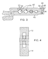
FIG. 3 is a cross-sectional view taken along line 3-3 of FIG. 1 of the present invention.
FIG. 4 is a cross-sectional view taken along line 4-4 of FIG. 1 of the present invention.
FIG. 5 is a perspective view of a second embodiment of the present invention.
FIG. 6 is a top enlarged view of the second embodiment of the present invention.
FIG. 7 is a perspective in-use view of a third embodiment of the present invention.
FIG. 8 is a perspective view of the third embodiment the present invention.
FIG. 9 is a perspective view of the third embodiment of the present invention.
DESCRIPTION OF THE PREFERRED EMBODIMENT
With reference now to the drawings, and in particular to FIGS. 1 through 9 thereof, a new cleaning device embodying the principles and concepts of the present invention and generally designated by the reference numeral 10 will be described.
As best illustrated in FIGS. 1 through 9, the fastener thread cleaning apparatus 10 generally comprises a first arm 12 and a second arm 14. Each of the first 12 and second 14 arms each has a first end 16 and a second end 18. The first 12 and second 14 arms are pivotally coupled together adjacent to the first ends to define a pair of jaws 20 that are selectively positioned in a closed position abutting each other or in an open position spaced from each other. An abutting side 22 of each of the of the first 12 and second 14 arms is defined and abut each other when the pair of jaws 20 is positioned in the closed position. Each of the of the abutting sides 22 has a plurality of semi-circular depressions 24 therein. Each of the depressions 24 in the first arm 12 is alignable with one of the depressions 24 in the second arm 14 to define apertures 26 extending through the pair of jaws 20 when the pair of jaws 20 is in the closed position. The apertures 26 each have a different diameter with respect to each other. The apertures 26 are each threaded. Each of the apertures 26 includes non-threaded sections 28 interspersed between threaded sections 30.
A first embodiment of the apparatus 10, shown in FIGS. 1 and 2, includes handles 32 attached to the first ends 12. A second embodiment is shown in FIGS. 5 and 6 and does not include handles 32. A third embodiment is shown in FIGS. 7-9 and only includes one aperture 26.
A locking member 34 is mounted on the pair of jaws 20 for selectively securing the pair of jaws 20 in the closed position. The locking member 34 comprises a rod 36 extending into a notch 38 in the second end 18 of the second arm 14 and is pivotally coupled to the second arm 14. Each of the first 12 and second 14 arms has an outer side 40 positioned opposite of a corresponding one of the abutting sides 22. The notch 38 in the second arm 14 extends through the outer side 40 and abutting side 22 of the second arm 14. The rod 36 is selectively positionable into a notch 44 extending into the second end 18 of the first arm 12. A free end 46 of the rod 36 extends outwardly away from the outer side 40 of the first arm 12. The rod 36 is threaded. A disc 48 has an opening 50 extending therethrough. The opening 50 is threaded. The rod 36 extends through and is threadably coupled to the disc 48. The disc 48 may be abutted against the outer side 40 of the first arm 12 when the pair of jaws 20 is in the closed position to secure the pair of jaws 20 in the closed position.
In the third embodiment, a perimeter wall 52 is attached to the pair of jaws 20 and extends around the aperture 26 when the pair of jaws 20 is positioned in the closed position. The perimeter wall 52 includes a first portion 54 attached to the first arm 12 and a second portion 56 attached to the second arm 14. The perimeter wall 52 has a hexagonal shape and has a size substantially equal to the size of the bolt head. A second perimeter wall 58 may be positioned on an opposite side of the jaws 20. The perimeter wall 52 allows a socket 9 to be attached to the jaws 20 for easy rotation of the jaws 20 with respect to a bolt 6.
In use, the pair of jaws 20 may be closed around a bolt 6 to threadably engage the bolt 6 with one of the apertures 26. The pair of jaws 20 is positioned between a head 7 and an end 8 of the bolt 6. The bolt 6 is then rotated to move the pair of jaws 20 toward the end 8 of the bolt 6. As the jaws 20 are rotated with respect to the bolt 6, the threads 30 in the apertures 26 clean the threads of the bolt 8. The non-threaded sections 28 collect the debris removed from the bolt 6.
With respect to the above description then, it is to be realized that the optimum dimensional relationships for the parts of the invention, to include variations in size, materials, shape, form, function and manner of operation, assembly and use, are deemed readily apparent and obvious to one skilled in the art, and all equivalent relationships to those illustrated in the drawings and described in the specification are intended to be encompassed by the present invention.
Therefore, the foregoing is considered as illustrative only of the principles of the invention. Further, since numerous modifications and changes will readily occur to those skilled in the art, it is not desired to limit the invention to the exact construction and operation shown and described, and accordingly, all suitable modifications and equivalents may be resorted to, falling within the scope of the invention.

Claims (7)

1. A cleaning tool for cleaning threads of a bolt, said tool comprising:
a first arm and a second arm, each of said first and second arms having a first end and a second end, said first and second arms being pivotally coupled together adjacent to said first ends to define a pair of jaws being selectively positioned in a closed position abutting each other or in an open position spaced from each other, an abutting side of each of said of said first and second arms being defined and abutting each other when said pair of jaws is positioned in said closed position, each of said abutting sides having at least the semi-circular depression therein, said at least one depression in said first arm being alignable with said at least one depression in said second arm to define at least one aperture through said pair of jaws when said pair of jaws is in said closed position, said at least one aperture being threaded;
a perimeter wall being attached to said pair of jaws and extending around said at least one aperture when said pair of jaws is positioned in said closed position, said perimeter wall including a first portion attached to said first arm and a second portion attached to said second arm, said perimeter wall having a hexagonal shape and having a size substantially equal to the size of the bolt head; and
wherein said pair of jaws may be closed around a bolt to threadably engage the bolt with said at least one aperture, said pair of jaws being positioned between a head and an end of the bolt, wherein the bolt is rotated to move said pair of jaws toward the end of the bolt.
2. The tool according to claim 1, wherein said at least one aperture includes non-threaded sections interspersed between threaded sections.
3. The tool according to claim 2, further including a locking member being mounted on said pair of jaws for selectively securing said pair of jaws in said closed position.
4. The tool according to claim 3, wherein said locking member comprises:
a rod extending into a notch in said second end of said second arm and being pivotally coupled to said second arm, each of said first and second arms having an outer side positioned opposite of a corresponding one of said abutting sides, said notch in said second arm extending through said outer and abutting sides of said second arm, said rod being selectively positionable into a notch extending into said second arm of said first arm, wherein a free end of said rod extends outwardly away from said outer side of said first arm, said rod being threaded; and
a disc having an opening extending therethrough, said opening being threaded said rod extending through and being threadably coupled to said disc, wherein said disc may be abutted against said outer side of said first arm when said pair of jaws is in said closed position to secure said pair of jaws in said closed position.
5. The tool according to claim 1, wherein said at least one aperture includes non-threaded sections interspersed between threaded sections.
6. The tool according to claim 5, further including a locking member being mounted on said pair of jaws for selectively securing said pair of jaws in said closed position.
7. The tool according to claim 1, further including a locking member being mounted on said pair of jaws for selectively securing said pair of jaws in said closed position.
US11/503,887 2006-08-15 2006-08-15 Fastener thread cleaning apparatus Expired - Fee Related US7418756B1 (en)

Priority Applications (1)

Application Number Priority Date Filing Date Title
US11/503,887 US7418756B1 (en) 2006-08-15 2006-08-15 Fastener thread cleaning apparatus

Applications Claiming Priority (1)

Application Number Priority Date Filing Date Title
US11/503,887 US7418756B1 (en) 2006-08-15 2006-08-15 Fastener thread cleaning apparatus

Publications (1)

Publication Number Publication Date
US7418756B1 true US7418756B1 (en) 2008-09-02

Family

ID=39718308

Family Applications (1)

Application Number Title Priority Date Filing Date
US11/503,887 Expired - Fee Related US7418756B1 (en) 2006-08-15 2006-08-15 Fastener thread cleaning apparatus

Country Status (1)

Country Link
US (1) US7418756B1 (en)

Cited By (6)

* Cited by examiner, † Cited by third party
Publication number Priority date Publication date Assignee Title
US20090178324A1 (en) * 2008-01-11 2009-07-16 James Vester Hopper Rifle bolt cleaning tool
US20110113669A1 (en) * 2009-09-11 2011-05-19 Gregory Oselinsky AR15/M16 Rifle Variant Bolt Cleaning and Polishing Tool
US20120079867A1 (en) * 2010-10-01 2012-04-05 Raytheon Company Tool for deforming threads at a particular location on a fastener
ITUD20100221A1 (en) * 2010-11-30 2012-05-31 Francesca Venzi MECHANICAL DEVICE TO RESTORE THE THREAD
US8794882B2 (en) 2010-07-08 2014-08-05 Chase 'Em Back Tools LLC Releasable thread chaser
CN110450035A (en) * 2019-09-17 2019-11-15 陕西陕煤韩城矿业有限公司 A kind of mining device removed bolt corrosion and repair bolt

Citations (12)

* Cited by examiner, † Cited by third party
Publication number Priority date Publication date Assignee Title
US522471A (en) * 1894-07-03 Combination-tool for pipe-fitting
US816570A (en) * 1904-10-28 1906-04-03 Edmonds Metzel Mfg Company Tool for straightening bolts and retracing the threads thereon.
US1042318A (en) * 1911-07-22 1912-10-22 John W Chamberlain Combination-tool.
US1521647A (en) * 1922-10-31 1925-01-06 Perry Tool Company Thread-reforming device
US1606186A (en) * 1921-01-21 1926-11-09 Herman G Schaefer Tool for rethreading bolts
US4346491A (en) 1979-11-13 1982-08-31 Rethread, Inc. Thread repair tool
US4603605A (en) 1983-11-01 1986-08-05 Miller Richard E Thread vise
US5288181A (en) * 1993-04-29 1994-02-22 Pinkston Donald L Rethreading tool
USD375667S (en) 1995-05-04 1996-11-19 Proprietary Technologies, Inc. Multi-socket, box wrench
US6206620B1 (en) 1998-04-22 2001-03-27 Brian D. Burns Thread chasing tool and method
US20030091401A1 (en) 2001-11-09 2003-05-15 Thompson William J. Thread cleaning tool
US6921236B2 (en) 2002-11-05 2005-07-26 Edward Rahberger Tool for repairing damaged threads

Patent Citations (12)

* Cited by examiner, † Cited by third party
Publication number Priority date Publication date Assignee Title
US522471A (en) * 1894-07-03 Combination-tool for pipe-fitting
US816570A (en) * 1904-10-28 1906-04-03 Edmonds Metzel Mfg Company Tool for straightening bolts and retracing the threads thereon.
US1042318A (en) * 1911-07-22 1912-10-22 John W Chamberlain Combination-tool.
US1606186A (en) * 1921-01-21 1926-11-09 Herman G Schaefer Tool for rethreading bolts
US1521647A (en) * 1922-10-31 1925-01-06 Perry Tool Company Thread-reforming device
US4346491A (en) 1979-11-13 1982-08-31 Rethread, Inc. Thread repair tool
US4603605A (en) 1983-11-01 1986-08-05 Miller Richard E Thread vise
US5288181A (en) * 1993-04-29 1994-02-22 Pinkston Donald L Rethreading tool
USD375667S (en) 1995-05-04 1996-11-19 Proprietary Technologies, Inc. Multi-socket, box wrench
US6206620B1 (en) 1998-04-22 2001-03-27 Brian D. Burns Thread chasing tool and method
US20030091401A1 (en) 2001-11-09 2003-05-15 Thompson William J. Thread cleaning tool
US6921236B2 (en) 2002-11-05 2005-07-26 Edward Rahberger Tool for repairing damaged threads

Cited By (11)

* Cited by examiner, † Cited by third party
Publication number Priority date Publication date Assignee Title
US20090178324A1 (en) * 2008-01-11 2009-07-16 James Vester Hopper Rifle bolt cleaning tool
US7644529B2 (en) 2008-01-11 2010-01-12 Combat Application Tools, Inc. Rifle bolt cleaning tool
US20110113669A1 (en) * 2009-09-11 2011-05-19 Gregory Oselinsky AR15/M16 Rifle Variant Bolt Cleaning and Polishing Tool
US8528144B2 (en) * 2009-09-11 2013-09-10 Gregory Oselinsky AR15/M16 rifle variant bolt cleaning and polishing tool
US8794882B2 (en) 2010-07-08 2014-08-05 Chase 'Em Back Tools LLC Releasable thread chaser
US20120079867A1 (en) * 2010-10-01 2012-04-05 Raytheon Company Tool for deforming threads at a particular location on a fastener
US8893593B2 (en) * 2010-10-01 2014-11-25 Raytheon Company Tool for deforming threads at a particular location on a fastener
AU2011307580B2 (en) * 2010-10-01 2014-11-27 Raytheon Company Tool for deforming threads at a particular location on a fastener
GB2498307B (en) * 2010-10-01 2015-09-02 Raytheon Co Tool for deforming threads at a particular location on a fastener
ITUD20100221A1 (en) * 2010-11-30 2012-05-31 Francesca Venzi MECHANICAL DEVICE TO RESTORE THE THREAD
CN110450035A (en) * 2019-09-17 2019-11-15 陕西陕煤韩城矿业有限公司 A kind of mining device removed bolt corrosion and repair bolt

Similar Documents

Publication Publication Date Title
US7418756B1 (en) Fastener thread cleaning apparatus
US6186032B1 (en) Wrench
EP3084235B1 (en) Temporary fastener
US7610833B2 (en) Thread gripping tool
US20190337131A1 (en) Fastener Extractor and Dislodging Tool Apparatus
AU2019344595A1 (en) Fastener extractor and dislodging tool apparatus
US20110192259A1 (en) Wrench
US20120318107A1 (en) Thread chaser
US8529171B1 (en) Apparatus facilitating removal of broken fasteners from an engine
US6435064B1 (en) Frost proof sill cock extraction tool
US10919130B2 (en) Wrench
CN204604195U (en) Five metals spanner
KR200483128Y1 (en) Wrench set for changing one-hole washbowl faucet and sink faucet
US8826778B1 (en) Apparatus and method for tightening or loosening toilet seat
US20150273665A1 (en) Wrench, drain retainer nut
JP2016077963A (en) Bolt cleaning tool
US20170136615A1 (en) Wrench System
TWM519572U (en) Locking pliers
US20150360349A1 (en) Bonnet Nut Socket
US6431032B1 (en) Alex wrench
JP6545558B2 (en) Tool and method of attaching and detaching fastener using the same
JP3200689U (en) Box wrench
KR20120100437A (en) Nut wrench
JP2019018256A (en) wrench
US5897151A (en) Tool handle mount

Legal Events

Date Code Title Description
STCF Information on status: patent grant

Free format text: PATENTED CASE

FPAY Fee payment

Year of fee payment: 4

REMI Maintenance fee reminder mailed
FPAY Fee payment

Year of fee payment: 8

SULP Surcharge for late payment

Year of fee payment: 7

FEPP Fee payment procedure

Free format text: MAINTENANCE FEE REMINDER MAILED (ORIGINAL EVENT CODE: REM.); ENTITY STATUS OF PATENT OWNER: SMALL ENTITY

LAPS Lapse for failure to pay maintenance fees

Free format text: PATENT EXPIRED FOR FAILURE TO PAY MAINTENANCE FEES (ORIGINAL EVENT CODE: EXP.); ENTITY STATUS OF PATENT OWNER: SMALL ENTITY

STCH Information on status: patent discontinuation

Free format text: PATENT EXPIRED DUE TO NONPAYMENT OF MAINTENANCE FEES UNDER 37 CFR 1.362

FP Lapsed due to failure to pay maintenance fee

Effective date: 20200902