US7418075B2 - Subtle dynamic helical scan for uniform z-resolution and noise - Google Patents
Subtle dynamic helical scan for uniform z-resolution and noise Download PDFInfo
- Publication number
- US7418075B2 US7418075B2 US11/331,172 US33117206A US7418075B2 US 7418075 B2 US7418075 B2 US 7418075B2 US 33117206 A US33117206 A US 33117206A US 7418075 B2 US7418075 B2 US 7418075B2
- Authority
- US
- United States
- Prior art keywords
- ray
- detector
- vol
- scanning device
- platform
- Prior art date
- Legal status (The legal status is an assumption and is not a legal conclusion. Google has not performed a legal analysis and makes no representation as to the accuracy of the status listed.)
- Expired - Fee Related
Links
Images


Classifications
-
- G—PHYSICS
- G01—MEASURING; TESTING
- G01N—INVESTIGATING OR ANALYSING MATERIALS BY DETERMINING THEIR CHEMICAL OR PHYSICAL PROPERTIES
- G01N23/00—Investigating or analysing materials by the use of wave or particle radiation, e.g. X-rays or neutrons, not covered by groups G01N3/00 – G01N17/00, G01N21/00 or G01N22/00
- G01N23/02—Investigating or analysing materials by the use of wave or particle radiation, e.g. X-rays or neutrons, not covered by groups G01N3/00 – G01N17/00, G01N21/00 or G01N22/00 by transmitting the radiation through the material
- G01N23/04—Investigating or analysing materials by the use of wave or particle radiation, e.g. X-rays or neutrons, not covered by groups G01N3/00 – G01N17/00, G01N21/00 or G01N22/00 by transmitting the radiation through the material and forming images of the material
- G01N23/046—Investigating or analysing materials by the use of wave or particle radiation, e.g. X-rays or neutrons, not covered by groups G01N3/00 – G01N17/00, G01N21/00 or G01N22/00 by transmitting the radiation through the material and forming images of the material using tomography, e.g. computed tomography [CT]
-
- A—HUMAN NECESSITIES
- A61—MEDICAL OR VETERINARY SCIENCE; HYGIENE
- A61B—DIAGNOSIS; SURGERY; IDENTIFICATION
- A61B6/00—Apparatus for radiation diagnosis, e.g. combined with radiation therapy equipment
- A61B6/02—Devices for diagnosis sequentially in different planes; Stereoscopic radiation diagnosis
- A61B6/027—Devices for diagnosis sequentially in different planes; Stereoscopic radiation diagnosis characterised by the use of a particular data acquisition trajectory, e.g. helical or spiral
-
- A—HUMAN NECESSITIES
- A61—MEDICAL OR VETERINARY SCIENCE; HYGIENE
- A61B—DIAGNOSIS; SURGERY; IDENTIFICATION
- A61B6/00—Apparatus for radiation diagnosis, e.g. combined with radiation therapy equipment
- A61B6/02—Devices for diagnosis sequentially in different planes; Stereoscopic radiation diagnosis
- A61B6/03—Computerised tomographs
- A61B6/032—Transmission computed tomography [CT]
-
- G—PHYSICS
- G01—MEASURING; TESTING
- G01N—INVESTIGATING OR ANALYSING MATERIALS BY DETERMINING THEIR CHEMICAL OR PHYSICAL PROPERTIES
- G01N2223/00—Investigating materials by wave or particle radiation
- G01N2223/40—Imaging
- G01N2223/419—Imaging computed tomograph
-
- G—PHYSICS
- G01—MEASURING; TESTING
- G01N—INVESTIGATING OR ANALYSING MATERIALS BY DETERMINING THEIR CHEMICAL OR PHYSICAL PROPERTIES
- G01N2223/00—Investigating materials by wave or particle radiation
- G01N2223/60—Specific applications or type of materials
- G01N2223/612—Specific applications or type of materials biological material
Definitions
- the present invention relates generally to a computed tomography (CT) apparatus and the reconstruction of medical images. More particularly, the invention relates to a CT apparatus that uses a plurality of rows of detectors for detecting an image formed by the helical scanning of a subject with a small helical pitch so as to create more uniform noise and resolution in the z-direction.
- CT computed tomography
- Dynamic cone-beam (4D) scanning has recently drawn increased interest. Dynamic cone beam (4D) scanning requires that the same location of an organ of interest be constantly scanned for a certain period of time. Thus, a circular scan is desired.
- FIG. 1 graphically depicts the “sweet-and-sore-spot phenomena” by the plurality of alternating “hot spot” and “cold spot” regions along the z-axis.
- the sampling patterns i.e., the position of cold spots and hot spots
- ⁇ radians apart match each other, as shown in FIG. 1 .
- circular scans result in the reconstructed image having a strong noise variation along the z-axis.
- FIG. 2 shows a plot comparing the standard deviation (image noise) normalized by the standard deviation of fan-beam reconstruction ( ⁇ 0 ) along the z-axis (i.e., ⁇ cone-beanm / ⁇ 0 ) with the z-resolution.
- the image noise is as large as fan-beam reconstruction at the center of the detector rows (i.e., near the middle of two tick marks).
- the image noise is approximately 70% (or 1/ ⁇ square root over (2) ⁇ ) of fan-beam reconstruction in between two detectors rows (i.e., on each tick mark).
- the z-resolution shows the opposite phenomena; the resolution at the center of the detector rows is as good as fan-beam reconstruction, while the resolution is about twice as broad when in between two detector rows.
- FIGS. 3 and 4 of reference [1] the results of the conventional technique of using z-increment (pitch) of 0.5 (mm/slice) are shown.
- FIGS. 3 and 4 of reference [1] clearly show that the images are blurred due to insufficient temporal resolution.
- references [3] and [4] describe a prototype 256-MDCT with a wide-area cylindrical 2D detector.
- the development of the 16-MDCT made dynamic 3D imaging possible.
- the craniocaudal coverage of the 16-MDCT scanner's detector, without gantry movement imposes a limit on cine imaging.
- the prototype 256-MDCT was developed to make cine imaging with a wider coverage.
- the 256-MDCT scans continuously at the same position (i.e., table remains stationary).
- the 256-MDCT suffers from the sweet-and-sore-spot phenomena noted above.
- the present invention seeks to provide a method, apparatus, and computer program product for producing images that are space-independent, have uniform z-resolution, and have uniform noise in the z-direction.
- a computed tomography apparatus including: an X-ray helical scanning device including an X-ray generator and X-ray detector arranged in gantry, the helical scanning device configured to provide a continuous scan and to obtain projection data of a scanned object arranged on a platform; and a control unit configured to control at least one of the X-ray helical scanning device and the platform so as to generate the continuous scan with a helical pitch that is based on a height of a detector row of the X-ray detector projected onto an iso-center of the gantry.
- control unit of the computed tomography apparatus is configured to generate the scan in which the helical pitch is equal to the height of the detector row of the X-ray detector projected onto an iso-center of the gantry.
- control unit of the computed tomography apparatus is configured to generate the scan in which the helical pitch is equal to one-half of the height of the detector row of the X-ray detector projected onto an iso-center of the gantry.
- the computed tomography apparatus further includes an image reconstructing device configured to reconstruct an image based on the obtained projection data using cone-beam reconstruction.
- control unit of the computed tomography apparatus is configured to generate the scan in which a period of time spent imaging a given volume of the object is defined by
- t cov ⁇ ( z vol ) ( D - z vol ) ⁇ t rot H , in which t cov is time coverage, z vol is the given volume, t rot is the time period per gantry rotation, D is the detector height at the iso-center, and H is the helical pitch.
- a method of performing computed tomography includes: obtaining projection data of a scanned object arranged on a platform using an X-ray helical scanning device including an X-ray generator and X-ray detector arranged in a gantry configured to perform a continuous scan of the object, wherein the obtaining step includes controlling movement of at least one of the X-ray device and the platform so as to generate the continuous scan with a helical pitch that is based on a height of a detector row of the X-ray detector projected onto an iso-center of the gantry.
- the helical pitch in the method of performing computed tomography is equal to the height of the detector row of the X-ray detector projected onto an iso-center of the gantry.
- the helical pitch in the method of performing computed tomography is equal to one-half of the height of the detector row of the X-ray detector projected onto an iso-center of the gantry.
- the method of performing computed further includes reconstructing an image based on the projection data using cone-beam reconstruction.
- the method of performing computed further includes imaging a given volume of the object for a period of time defined
- ⁇ ⁇ t cov ⁇ ( z vol ) ( D - z vol ) ⁇ t rot H , in which t cov is time coverage, z vol is the given volume, t rot is the time period per gantry rotation, D is the detector height at the iso-center, and H is the helical pitch.
- a computer readable medium stores instructions for execution on a computer system, which when executed by the computer system, causes the computer system to perform steps including: obtaining projection data of a scanned object arranged on a platform using an X-ray helical scanning device including an X-ray generator and X-ray detector arranged in a gantry configured to perform a continuous scan of the object, wherein the obtaining step includes controlling movement of at least one of the X-ray device and the platform so as to generate the continuous scan with a helical pitch that is based on a height of a detector row of the X-ray detector projected onto an iso-center of the gantry.
- FIG. 1 illustrates two sampling patterns used with a conventional CT-apparatus
- FIG. 2 illustrates a plot of z-resolution vs. image noise
- FIG. 3 illustrates a CT-apparatus
- FIG. 4 is a CT scanning system showing a helical pitch
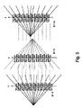
- FIG. 5 illustrates three sampling patterns used with a first embodiment of the present invention
- FIG. 6 illustrates three sampling patterns used with a second embodiment of the present invention
- FIG. 7 illustrates a method used to perform computed tomography
- FIG. 8 is a block diagram of a computer system upon which an embodiment of the present invention may be implemented.
- FIG. 3 shows an x-ray computed-topographic imaging device that can be used to obtain data that is processed by methods of the present invention.
- the projection data measurement system constituted by gantry 1 accommodates an x-ray source 3 that generates a cone-beam of x-ray flux approximately cone-shaped, and a two-dimensional array type x-ray detector 5 consisting of a plurality of detector elements arranged in a two-dimensional fashion, i.e., a plurality of elements arranged in one dimension stacked in a plurality of rows.
- X-ray source 3 and two-dimensional array type x-ray detector 5 are installed on a rotating ring 2 in facing opposite sides of a subject, who is laid on a sliding sheet of a bed or platform 6 .
- Two-dimensional array type x-ray detector 5 is mounted on rotating ring 2 . Each detector element corresponds to one channel.
- X-rays from x-ray source 3 are directed on to subject through an x-ray filter 4 .
- X-rays that have passed through the subject are detected as an electrical signal by two-dimensional array type x-ray detector 5 .
- X-ray controller 8 supplies a trigger signal to high voltage generator 7 .
- High voltage generator 7 applies high voltage to x-ray source 3 based on the timing with which the trigger signal is received. This causes x-rays to be emitted from x-ray source 3 .
- Gantry/bed controller 9 synchronously controls the revolution of rotating ring 2 of gantry 1 and the sliding of the sliding sheet of bed 6 .
- System controller 10 constitutes the control center of the entire system and controls x-ray controller 8 and gantry/bed controller 9 such that, as seen from the subject, x-ray source 3 executes so-called helical scanning, in which the X-ray source moves along a helical path. Specifically, rotating ring 2 is continuously rotated with fixed angular speed while the sliding plate is displaced with fixed speed, and x-rays are emitted continuously or intermittently at fixed angular intervals from x-ray source 3 .
- the output signal of two-dimensional array type x-ray detector 5 is amplified by a data collection unit 11 for each channel and converted to a digital signal to produce projection data.
- the projection data that is output from data collection unit 11 is fed to reconstruction processing unit 12 .
- Reconstruction processing unit 12 uses the projection data to find backprojection data reflecting the x-ray absorption in each voxel.
- the imaging region (effective field of view) is a cylindrical shape with radius ⁇ centered on the axis of revolution.
- Reconstruction processing unit 12 defines a plurality of voxels in this imaging region, and finds the backprojection data for each voxel.
- the three-dimensional image data or tomographic image data compiled by using this backprojection data is sent to display device 14 , where it is displayed visually as a three-dimensional image or tomographic image.
- an image to be a representation of a physical scene, in which the image has been generated by some imaging technology.
- imaging technology could include television or CCD cameras or X-ray, sonar or ultrasound imaging devices.
- the initial medium on which an image is recorded could be an electronic solid-state device, a photographic film, or some other device such as a photostimulable phosphor. That recorded image could then be converted into digital form by a combination of electronic (as in the case of a CCD signal) or mechanical/optical means (as in the case of digitizing a photographic film or digitizing the data from a photostimulable phosphor).
- a subtle helical scan is implemented.
- the subtle helical scan conducts a helical scan with an extremely small helical pitch.
- a CT-apparatus based on a subtle helical scan collects tomographic image data of a subject to be examined by moving a subject on a platform in a body axial direction of subject 42 , along the z-axis, in synchronization with a continuous rotation of radiation source 43 and a detector 41 .
- an extremely small helical pitch is used.
- the helical pitch corresponds to the height of one detector row at the iso-center.
- the sweet-and-sore-spot phenomena noted above results from the sampling pattern of the data acquisition.
- voxels at the z-axis have a constant sampling pattern.
- cone-beam data from two detector rows are axially interpolated with a weight of 0.5 each over the entire projection angular range.
- the interpolation results in some of the voxels being blurred along the z-axis; while other voxels have a weight of 1.0 and 0.0 for sharp resolution.
- the subtle helical scan provides a reasonably long period of time to image the volume of interest.
- the time-coverage t cov of a given volume z vol is provided by
- t cov ⁇ ( z vol ) ( D - z vol ) ⁇ t rot H , ( 2 )
- D the detector height at the iso-center [mm]
- H the helical pitch [mm/rev].
- the helical pitch is made to correspond to the height of one-half a detector row at the iso-center.
- FIG. 6 shows sampling patterns used in the second embodiment of the present invention.
- the interlacing of hot and cold spots shown in FIG. 6 is not as close as in the first embodiment shown in FIG. 5 .
- Image reconstruction may be done using known cone-beam reconstruction techniques, which are described in reference [8] with weightings.
- the difference between the actual rotation about the vertical axis and the equivalent rotation about the normal to the plane must be corrected for. Further, the source-to-detector distance in the tilted plane must be substituted into the Radon transform. After making these corrections, the increment of reconstructed density is obtained.
- the total density at a point r is taken to be the sum of the incremental contributions from all planes (one for each rotation angle) that pass through r.
- the planes of projection that contribute to the reconstruction at a given r may be visualized as forming a sheaf. Except for points in the midplane, the sheaf for each reconstruction point is unique.
- FIG. 7 illustrates a method of computed tomography for an embodiment of the claimed invention.
- X-rays are generated from an X-ray source.
- a continuous scan of an object on a platform of a helical scanning device is conducted.
- the platform is moved in a body axial direction of the object on the platform.
- the helical pitch created by the movement of the platform may be equal to either of the height of a detector row or one-half the height of a detector row.
- a given volume of the object is imaged for a period of time.
- projection data is collected.
- an image is reconstructed based on the projection data, which may be done using cone-beam reconstruction.
- FIG. 8 illustrates a computer system 1201 upon which an embodiment of the present invention may be implemented.
- the computer system 1201 includes a bus 1202 or other communication mechanism for communicating information, and a processor 1203 coupled with the bus 1202 for processing the information.
- the computer system 1201 also includes a main memory 1204 , such as a random access memory (RAM) or other dynamic storage device (e.g., dynamic RAM (DRAM), static RAM (SRAM), and synchronous DRAM (SDRAM)), coupled to the bus 1202 for storing information and instructions to be executed by processor 1203 .
- the main memory 1204 may be used for storing temporary variables or other intermediate information during the execution of instructions by the processor 1203 .
- the computer system 1201 further includes a read only memory (ROM) 1205 or other static storage device (e.g., programmable ROM (PROM), erasable PROM (EPROM), and electrically erasable PROM (EEPROM)) coupled to the bus 1202 for storing static information and instructions for the processor 1203 .
- ROM read only memory
- PROM programmable ROM
- EPROM erasable PROM
- EEPROM electrically erasable PROM
- the computer system 1201 also includes a disk controller 1206 coupled to the bus 1202 to control one or more storage devices for storing information and instructions, such as a magnetic hard disk 1207 , and a removable media drive 1208 (e.g., floppy disk drive, read-only compact disc drive, read/write compact disc drive, compact disc jukebox, tape drive, and removable magneto-optical drive).
- a removable media drive 1208 e.g., floppy disk drive, read-only compact disc drive, read/write compact disc drive, compact disc jukebox, tape drive, and removable magneto-optical drive.
- the storage devices may be added to the computer system 1201 using an appropriate device interface (e.g., small computer system interface (SCSI), integrated device electronics (IDE), enhanced-IDE (E-IDE), direct memory access (DMA), or ultra-DMA).
- SCSI small computer system interface
- IDE integrated device electronics
- E-IDE enhanced-IDE
- DMA direct memory access
- ultra-DMA ultra-DMA
- the computer system 1201 may also include special purpose logic devices (e.g., application specific integrated circuits (ASICs)) or configurable logic devices (e.g., simple programmable logic devices (SPLDs), complex programmable logic devices (CPLDs), and field programmable gate arrays (FPGAs)).
- ASICs application specific integrated circuits
- SPLDs simple programmable logic devices
- CPLDs complex programmable logic devices
- FPGAs field programmable gate arrays
- the computer system 1201 may also include a display controller 1209 coupled to the bus 1202 to control a display 1210 , such as a cathode ray tube (CRT), for displaying information to a computer user.
- the computer system includes input devices, such as a keyboard 1211 and a pointing device 1212 , for interacting with a computer user and providing information to the processor 1203 .
- the pointing device 1212 may be a mouse, a trackball, or a pointing stick for communicating direction information and command selections to the processor 1203 and for controlling cursor movement on the display 1210 .
- a printer may provide printed listings of data stored and/or generated by the computer system 1201 .
- the computer system 1201 performs a portion or all of the processing steps of the invention in response to the processor 1203 executing one or more sequences of one or more instructions contained in a memory, such as the main memory 1204 .
- a memory such as the main memory 1204 .
- Such instructions may be read into the main memory 1204 from another computer readable medium, such as a hard disk 1207 or a removable media drive 1208 .
- processors in a multi-processing arrangement may also be employed to execute the sequences of instructions contained in main memory 1204 .
- hard-wired circuitry may be used in place of or in combination with software instructions. Thus, embodiments are not limited to any specific combination of hardware circuitry and software.
- the computer system 1201 includes at least one computer readable medium or memory for holding instructions programmed according to the teachings of the invention and for containing data structures, tables, records, or other data described herein.
- Examples of computer readable media are compact discs, hard disks, floppy disks, tape, magneto-optical disks, PROMs (EPROM, EEPROM, flash EPROM), DRAM, SRAM, SDRAM, or any other magnetic medium, compact discs (e.g., CD-ROM), or any other optical medium, punch cards, paper tape, or other physical medium with patterns of holes, a carrier wave (described below), or any other medium from which a computer can read.
- the present invention includes software for controlling the computer system 1201 , for driving a device or devices for implementing the invention, and for enabling the computer system 1201 to interact with a human user (e.g., print production personnel).
- software may include, but is not limited to, device drivers, operating systems, development tools, and applications software.
- Such computer readable media further includes the computer program product of the present invention for performing all or a portion (if processing is distributed) of the processing performed in implementing the invention.
- the computer code devices of the present invention may be any interpretable or executable code mechanism, including but not limited to scripts, interpretable programs, dynamic link libraries (DLLs), Java classes, and complete executable programs. Moreover, parts of the processing of the present invention may be distributed for better performance, reliability, and/or cost.
- Non-volatile media includes, for example, optical, magnetic disks, and magneto-optical disks, such as the hard disk 1207 or the removable media drive 1208 .
- Volatile media includes dynamic memory, such as the main memory 1204 .
- Transmission media includes coaxial cables, copper wire and fiber optics, including the wires that make up the bus 1202 . Transmission media also may also take the form of acoustic or light waves, such as those generated during radio wave and infrared data communications.
- Various forms of computer readable media may be involved in carrying out one or more sequences of one or more instructions to processor 1203 for execution.
- the instructions may initially be carried on a magnetic disk of a remote computer.
- the remote computer can load the instructions for implementing all or a portion of the present invention remotely into a dynamic memory and send the instructions over a telephone line using a modem.
- a modem local to the computer system 1201 may receive the data on the telephone line and use an infrared transmitter to convert the data to an infrared signal.
- An infrared detector coupled to the bus 1202 can receive the data carried in the infrared signal and place the data on the bus 1202 .
- the bus 1202 carries the data to the main memory 1204 , from which the processor 1203 retrieves and executes the instructions.
- the instructions received by the main memory 1204 may optionally be stored on storage device 1207 or 1208 either before or after execution by processor 1203 .
- the computer system 1201 also includes a communication interface 1213 coupled to the bus 1202 .
- the communication interface 1213 provides a two-way data communication coupling to a network link 1214 that is connected to, for example, a local area network (LAN) 1215 , or to another communications network 1216 such as the Internet.
- LAN local area network
- the communication interface 1213 may be a network interface card to attach to any packet switched LAN.
- the communication interface 1213 may be an asymmetrical digital subscriber line (ADSL) card, an integrated services digital network (ISDN) card or a modem to provide a data communication connection to a corresponding type of communications line.
- Wireless links may also be implemented.
- the communication interface 1213 sends and receives electrical, electromagnetic or optical signals that carry digital data streams representing various types of information.
- the network link 1214 typically provides data communication through one or more networks to other data devices.
- the network link 1214 may provide a connection to another computer through a local network 1215 (e.g., a LAN) or through equipment operated by a service provider, which provides communication services through a communications network 1216 .
- the local network 1214 and the communications network 1216 use, for example, electrical, electromagnetic, or optical signals that carry digital data streams, and the associated physical layer (e.g., CAT 5 cable, coaxial cable, optical fiber, etc).
- the signals through the various networks and the signals on the network link 1214 and through the communication interface 1213 , which carry the digital data to and from the computer system 1201 maybe implemented in baseband signals, or carrier wave based signals.
- the baseband signals convey the digital data as unmodulated electrical pulses that are descriptive of a stream of digital data bits, where the term “bits” is to be construed broadly to mean symbol, where each symbol conveys at least one or more information bits.
- the digital data may also be used to modulate a carrier wave, such as with amplitude, phase and/or frequency shift keyed signals that are propagated over a conductive media, or transmitted as electromagnetic waves through a propagation medium.
- the digital data may be sent as unmodulated baseband data through a “wired” communication channel and/or sent within a predetermined frequency band, different than baseband, by modulating a carrier wave.
- the computer system 1201 can transmit and receive data, including program code, through the network(s) 1215 and 1216 , the network link 1214 and the communication interface 1213 .
- the network link 1214 may provide a connection through a LAN 1215 to a mobile device 1217 such as a personal digital assistant (PDA) laptop computer, or cellular telephone.
- PDA personal digital assistant
- the computer housing may house a motherboard that contains a CPU, memory, and other optional special purpose logic devices (e.g., ASICS) or configurable logic devices (e.g., GAL and reprogrammable FPGA).
- ASICS special purpose logic devices
- GAL and reprogrammable FPGA configurable logic devices
- the computer also includes plural input devices, (e.g., keyboard and mouse), and a display card for controlling a monitor.
- the computer may include a floppy disk drive; other removable media devices (e.g. compact disc, tape, and removable magneto-optical media); and a hard disk or other fixed high density media drives, connected using an appropriate device bus (e.g., a SCSI bus, an Enhanced IDE bus, or an Ultra DMA bus).
- the computer may also include a compact disc reader, a compact disc reader/writer unit, or a compact disc jukebox, which may be connected to the same device bus or to another device bus.
- the present invention includes software for controlling both the hardware of the computer and for enabling the computer to interact with a human user.
- software may include, but is not limited to, device drivers, operating systems and user applications, such as development tools.
- Computer program products of the present invention include any computer readable medium which stores computer program instructions (e.g., computer code devices) which when executed by a computer causes the computer to perform the method of the present invention.
- the computer code devices of the present invention may be any interpretable or executable code mechanism, including but not limited to, scripts, interpreters, dynamic link libraries, Java classes, and complete executable programs.
- parts of the processing of the present invention may be distributed (e.g., between (1) multiple CPUs or (2) at least one CPU and at least one configurable logic device) for better performance, reliability, and/or cost.
- an outline or image may be selected on a first computer and sent to a second computer for remote diagnosis.
- the invention may also be implemented by the preparation of application specific integrated circuits or by interconnecting an appropriate network of conventional component circuits, as will be readily apparent to those skilled in the art.
- the source of image data to the present invention may be any appropriate image acquisition device such as an X-ray machine or CT apparatus.
- the acquired data may be digitized if not already in digital form.
Abstract
Description
-
- [1] Kasuyuki Taguchi, Temporal resolution and the evaluation of candidate algorithms for four dimensional CT, Med. Phys. 30(4), pp. 640-650, April 2003.
- [2] Chisato Kondo, et al., Real-time volumetric imaging of human heart without electrocardiographic gating by 256-detector row computed tomography, J Comput Assist Tomogr, Vol. 29, Number 5, pp. 694-698, September/October 2005.
- [3] Shinichiro Mori, et al., Clinical Potentials for Dynamic Contrast-Enhanced Hepatic Volumetric Cine Imaging with Prototype 256-MDCT Scanner, AJR: 185, pp. 253-256, July 2005.
- [4] Shinichiro Mori, et al., Volumetric Cine Imaging for Cardiovascular Circulation Using Prototype 256-Dectector Row Computed Tomography Scanner (4-Dimensional Computed Tomgraphy), J Comput Assist Tomogr, Vol. 29,
Number 1, pp. 26-30, January/February 2005. - [5] Ying Lu, et al., Half-scan cone-beam CT fluoroscopy with multiple x-ray sources, Med. Phys. 28 (7), pp. 1466-1471, July 2001.
- [6] Ge Wang, et al., A General Cone-Beam Reconstruction Algorithm, IEEE Transactions on Medical Imaging, Vol. 12, No. 3, pp. 486-496, September 1993.
- [7] H. Kudo and T. Saito, Helical-scan computed tomography using cone-beam projections, Nuclear Science Symposium and Medical Imaging Conference, pp. 1958-1962, November 1991.
- [8] L. A. Feldkamp, et al., Practical cone-beam algorithm, J. Opt Soc. Am A/Vol. 1, No. 6, pp. 612-619, June 1984.
- [9] Hein et al., U.S. Patent Publication No. 2004/0086075.
- [10] Nambu et al., U.S. Patent Publication No. 2003/0097076.
in which tcov is time coverage, zvol is the given volume, trot is the time period per gantry rotation, D is the detector height at the iso-center, and H is the helical pitch.
in which tcov is time coverage, zvol is the given volume, trot is the time period per gantry rotation, D is the detector height at the iso-center, and H is the helical pitch.
g(β,γ,α)≅g(β+π+2γ,−γ,α′) (1)
where β is the projection-angle, γ is the ray angle, and α is the cone angle, respectively. Although the similarity decreases with increasing α, the subtle helical scan remains a good approximation.
where D is the detector height at the iso-center [mm], and H is the helical pitch [mm/rev]. Thus, if the number of the detector row is 256, zvol is 50 mm, and H (=w) is 0.5 mm, then tcov is 78 seconds.
Claims (12)
Priority Applications (3)
| Application Number | Priority Date | Filing Date | Title |
|---|---|---|---|
| US11/331,172 US7418075B2 (en) | 2006-01-13 | 2006-01-13 | Subtle dynamic helical scan for uniform z-resolution and noise |
| JP2007001637A JP2007185510A (en) | 2006-01-13 | 2007-01-09 | Computer tomographic equipment |
| CN200710001706XA CN101077302B (en) | 2006-01-13 | 2007-01-12 | Computer tomographic equipment |
Applications Claiming Priority (1)
| Application Number | Priority Date | Filing Date | Title |
|---|---|---|---|
| US11/331,172 US7418075B2 (en) | 2006-01-13 | 2006-01-13 | Subtle dynamic helical scan for uniform z-resolution and noise |
Publications (2)
| Publication Number | Publication Date |
|---|---|
| US20070165774A1 US20070165774A1 (en) | 2007-07-19 |
| US7418075B2 true US7418075B2 (en) | 2008-08-26 |
Family
ID=38263155
Family Applications (1)
| Application Number | Title | Priority Date | Filing Date |
|---|---|---|---|
| US11/331,172 Expired - Fee Related US7418075B2 (en) | 2006-01-13 | 2006-01-13 | Subtle dynamic helical scan for uniform z-resolution and noise |
Country Status (3)
| Country | Link |
|---|---|
| US (1) | US7418075B2 (en) |
| JP (1) | JP2007185510A (en) |
| CN (1) | CN101077302B (en) |
Cited By (2)
| Publication number | Priority date | Publication date | Assignee | Title |
|---|---|---|---|---|
| US20160103026A1 (en) * | 2013-06-05 | 2016-04-14 | Ev Group E. Thallner Gmbh | Measuring device and method for ascertaining a pressure map |
| US9924910B2 (en) | 2011-01-14 | 2018-03-27 | Koninklijke Philips N.V. | 4D contrast enhanced computed tomography (CT) |
Citations (4)
| Publication number | Priority date | Publication date | Assignee | Title |
|---|---|---|---|---|
| US5390112A (en) * | 1993-10-04 | 1995-02-14 | General Electric Company | Three-dimensional computerized tomography scanning method and system for imaging large objects with smaller area detectors |
| US20030097076A1 (en) | 2001-10-16 | 2003-05-22 | Kyojiro Nambu | Method and apparatus for calculating index concerning local blood flow circulations |
| US20040086075A1 (en) | 2002-10-30 | 2004-05-06 | Kabushhiki Kaisha Toshiba | Titled gantry helical cone-beam Feldkamp reconstruction for multislice CT |
| US7046758B1 (en) * | 1999-11-10 | 2006-05-16 | Hitachi Medical Corporation | X-ray CT apparatus |
-
2006
- 2006-01-13 US US11/331,172 patent/US7418075B2/en not_active Expired - Fee Related
-
2007
- 2007-01-09 JP JP2007001637A patent/JP2007185510A/en not_active Withdrawn
- 2007-01-12 CN CN200710001706XA patent/CN101077302B/en not_active Expired - Fee Related
Patent Citations (4)
| Publication number | Priority date | Publication date | Assignee | Title |
|---|---|---|---|---|
| US5390112A (en) * | 1993-10-04 | 1995-02-14 | General Electric Company | Three-dimensional computerized tomography scanning method and system for imaging large objects with smaller area detectors |
| US7046758B1 (en) * | 1999-11-10 | 2006-05-16 | Hitachi Medical Corporation | X-ray CT apparatus |
| US20030097076A1 (en) | 2001-10-16 | 2003-05-22 | Kyojiro Nambu | Method and apparatus for calculating index concerning local blood flow circulations |
| US20040086075A1 (en) | 2002-10-30 | 2004-05-06 | Kabushhiki Kaisha Toshiba | Titled gantry helical cone-beam Feldkamp reconstruction for multislice CT |
Non-Patent Citations (8)
| Title |
|---|
| Chisato Kondo, et al., Real-Time Volumetric Imaging of Human Heart Without Electrocardiographic Gating by 256-Dectector Row Computed Tomography, Comput. Assist. Tomogr. vol. 29, No. 5, Sep./Oct. 2005, pp. 694-698. |
| Ge Wang, et al., A General Cone-Bream Reconstruction Algorithm, IEEE Transactions on Medical Imaging, vol. 12, No. 3, Sep. 1993, pp. 486-496. |
| Hiroyuki Kudo, et al., Helical-Scan Computed Tomography Using Cone-Beam Projections, Nuclear Science Symposium and Medical Imaging Conference, 1991, Conference Record of the 1991 IEEE, pp. 1958-1962. |
| Katsuyuki Taguchi, Temporal resolution and the evaluation of candidate algorithms for four-dimensional CT, Medical Physics, vol. 30, No. 4, Apr. 2003, 2003 Am. Assoc. Phys. Med., pp. 640-650. |
| L. A. Feldkamp, et al., Practical cone-beam algorithm, 1984 Optical Society of America, J. Opt. Soc. Am. A/vol. 1, No. 6/Jun. 1984, pp. 612-619. |
| Shinichiro Mori, et al., Clinical Potentials for Dynamic Contrast-Enhanced Hepatic Volumetric Cine Imaging with the Prototype 256-MDCT Scanner, AJR:185, Jul. 2005, pp. 253-256. |
| Shinichiro Mori, et al., Volumetric Cine Imaging for Cardiovascular Circulation Using Prototype 256-Detector Row Computed Tomography Scanner (4-Dimensional Computed Tomography), A Preliminary Study with a Porcine Model, Comput. Assist. Tomogr., vol. 29, No. 1, Jan./Feb. 2005, pp. 26-30. |
| Ying Liu, et al., Half-scan cone-beam CT fluoroscopy with multiple x-ray sources, 2001 Am. Assoc. Phys. Med., Medical Physics, vol. 28, No. 7, Jul. 2001, pp. 1466-1471. |
Cited By (4)
| Publication number | Priority date | Publication date | Assignee | Title |
|---|---|---|---|---|
| US9924910B2 (en) | 2011-01-14 | 2018-03-27 | Koninklijke Philips N.V. | 4D contrast enhanced computed tomography (CT) |
| US10219759B2 (en) | 2011-01-14 | 2019-03-05 | Koninklijke Philips N.V. | 4D contrast enhanced computed tomography (CT) |
| US20160103026A1 (en) * | 2013-06-05 | 2016-04-14 | Ev Group E. Thallner Gmbh | Measuring device and method for ascertaining a pressure map |
| US10024741B2 (en) * | 2013-06-05 | 2018-07-17 | Ev Group E. Thallner Gmbh | Measuring device and method for ascertaining a pressure map |
Also Published As
| Publication number | Publication date |
|---|---|
| CN101077302A (en) | 2007-11-28 |
| CN101077302B (en) | 2011-02-23 |
| JP2007185510A (en) | 2007-07-26 |
| US20070165774A1 (en) | 2007-07-19 |
Similar Documents
| Publication | Publication Date | Title |
|---|---|---|
| EP1324696B1 (en) | System and method for cone beam volume computed tomography using circle-plus-multiple-arc orbit | |
| US7515676B2 (en) | Method, apparatus, and computer program product for sinogram completion | |
| US7203272B2 (en) | Cone-beam filtered backprojection image reconstruction method for short trajectories | |
| US7251307B2 (en) | Fan-beam and cone-beam image reconstruction using filtered backprojection of differentiated projection data | |
| JP5019193B2 (en) | Reconstruction method and X-ray computed tomography apparatus for determining image data values at reconstruction points in a CT image related to a scan target | |
| US6141398A (en) | Protocol driven image reconstruction, display, and processing in a multislice imaging system | |
| US6435714B1 (en) | X-ray diagnostic device | |
| US8094910B2 (en) | Method of reconstructing an image function from Radon data | |
| US6904117B2 (en) | Tilted gantry helical cone-beam Feldkamp reconstruction for multislice CT | |
| US20070019776A1 (en) | Computer tomography method using a cone-shaped bundle of rays | |
| US8995735B2 (en) | System and method for wide cone helical image reconstruction using blending of two reconstructions | |
| US20090185656A1 (en) | Cone-beam ct half-cycle closed helical trajectory | |
| US7418075B2 (en) | Subtle dynamic helical scan for uniform z-resolution and noise | |
| JPH0998968A (en) | Method and device to create tomographic image of material body | |
| US7426257B2 (en) | Computer tomography method for a periodically moving object | |
| JP2002065663A (en) | Method and apparatus to reversibly impose imaging data | |
| Kalender et al. | Spiral CT: medical use and potential industrial applications | |
| US20200170587A1 (en) | Automated phase selection for ecg-gated cardiac axial ct scans | |
| JPH08505309A (en) | Reconstruction Method for Spiral Scan Computed Tomography Equipment with Multiple Row Detector Arrays | |
| Cierniak et al. | Spiral Tomography | |
| JPH082355B2 (en) | X-ray tomography system |
Legal Events
| Date | Code | Title | Description |
|---|---|---|---|
| AS | Assignment |
Owner name: TOSHIBA MEDICAL SYSTEMS CORPORATION, JAPAN Free format text: ASSIGNMENT OF ASSIGNORS INTEREST;ASSIGNOR:TAGUCHI, KATSUYUKI;REEL/FRAME:018012/0001 Effective date: 20060525 Owner name: KABUSHIKI KAISHA TOSHIBA, JAPAN Free format text: ASSIGNMENT OF ASSIGNORS INTEREST;ASSIGNOR:TAGUCHI, KATSUYUKI;REEL/FRAME:018012/0001 Effective date: 20060525 |
|
| REMI | Maintenance fee reminder mailed | ||
| LAPS | Lapse for failure to pay maintenance fees | ||
| STCH | Information on status: patent discontinuation |
Free format text: PATENT EXPIRED DUE TO NONPAYMENT OF MAINTENANCE FEES UNDER 37 CFR 1.362 |
|
| FP | Lapsed due to failure to pay maintenance fee |
Effective date: 20120826 |