US7409285B2 - Homogeneous charge compression ignition engine operation - Google Patents
Homogeneous charge compression ignition engine operation Download PDFInfo
- Publication number
- US7409285B2 US7409285B2 US11/739,142 US73914207A US7409285B2 US 7409285 B2 US7409285 B2 US 7409285B2 US 73914207 A US73914207 A US 73914207A US 7409285 B2 US7409285 B2 US 7409285B2
- Authority
- US
- United States
- Prior art keywords
- engine
- operating
- cylinder
- combustion
- temperature
- Prior art date
- Legal status (The legal status is an assumption and is not a legal conclusion. Google has not performed a legal analysis and makes no representation as to the accuracy of the status listed.)
- Expired - Fee Related
Links
Images


Classifications
-
- F—MECHANICAL ENGINEERING; LIGHTING; HEATING; WEAPONS; BLASTING
- F02—COMBUSTION ENGINES; HOT-GAS OR COMBUSTION-PRODUCT ENGINE PLANTS
- F02D—CONTROLLING COMBUSTION ENGINES
- F02D41/00—Electrical control of supply of combustible mixture or its constituents
- F02D41/30—Controlling fuel injection
- F02D41/3011—Controlling fuel injection according to or using specific or several modes of combustion
- F02D41/3017—Controlling fuel injection according to or using specific or several modes of combustion characterised by the mode(s) being used
- F02D41/3035—Controlling fuel injection according to or using specific or several modes of combustion characterised by the mode(s) being used a mode being the premixed charge compression-ignition mode
-
- F—MECHANICAL ENGINEERING; LIGHTING; HEATING; WEAPONS; BLASTING
- F02—COMBUSTION ENGINES; HOT-GAS OR COMBUSTION-PRODUCT ENGINE PLANTS
- F02B—INTERNAL-COMBUSTION PISTON ENGINES; COMBUSTION ENGINES IN GENERAL
- F02B1/00—Engines characterised by fuel-air mixture compression
- F02B1/12—Engines characterised by fuel-air mixture compression with compression ignition
-
- F—MECHANICAL ENGINEERING; LIGHTING; HEATING; WEAPONS; BLASTING
- F02—COMBUSTION ENGINES; HOT-GAS OR COMBUSTION-PRODUCT ENGINE PLANTS
- F02D—CONTROLLING COMBUSTION ENGINES
- F02D35/00—Controlling engines, dependent on conditions exterior or interior to engines, not otherwise provided for
- F02D35/02—Controlling engines, dependent on conditions exterior or interior to engines, not otherwise provided for on interior conditions
- F02D35/025—Controlling engines, dependent on conditions exterior or interior to engines, not otherwise provided for on interior conditions by determining temperatures inside the cylinder, e.g. combustion temperatures
- F02D35/026—Controlling engines, dependent on conditions exterior or interior to engines, not otherwise provided for on interior conditions by determining temperatures inside the cylinder, e.g. combustion temperatures using an estimation
-
- F—MECHANICAL ENGINEERING; LIGHTING; HEATING; WEAPONS; BLASTING
- F02—COMBUSTION ENGINES; HOT-GAS OR COMBUSTION-PRODUCT ENGINE PLANTS
- F02D—CONTROLLING COMBUSTION ENGINES
- F02D41/00—Electrical control of supply of combustible mixture or its constituents
- F02D41/0025—Controlling engines characterised by use of non-liquid fuels, pluralities of fuels, or non-fuel substances added to the combustible mixtures
- F02D41/0047—Controlling exhaust gas recirculation [EGR]
- F02D41/005—Controlling exhaust gas recirculation [EGR] according to engine operating conditions
- F02D41/0057—Specific combustion modes
-
- F—MECHANICAL ENGINEERING; LIGHTING; HEATING; WEAPONS; BLASTING
- F02—COMBUSTION ENGINES; HOT-GAS OR COMBUSTION-PRODUCT ENGINE PLANTS
- F02B—INTERNAL-COMBUSTION PISTON ENGINES; COMBUSTION ENGINES IN GENERAL
- F02B75/00—Other engines
- F02B75/12—Other methods of operation
- F02B2075/125—Direct injection in the combustion chamber for spark ignition engines, i.e. not in pre-combustion chamber
-
- F—MECHANICAL ENGINEERING; LIGHTING; HEATING; WEAPONS; BLASTING
- F02—COMBUSTION ENGINES; HOT-GAS OR COMBUSTION-PRODUCT ENGINE PLANTS
- F02D—CONTROLLING COMBUSTION ENGINES
- F02D41/00—Electrical control of supply of combustible mixture or its constituents
- F02D41/0002—Controlling intake air
- F02D2041/001—Controlling intake air for engines with variable valve actuation
-
- F—MECHANICAL ENGINEERING; LIGHTING; HEATING; WEAPONS; BLASTING
- F02—COMBUSTION ENGINES; HOT-GAS OR COMBUSTION-PRODUCT ENGINE PLANTS
- F02D—CONTROLLING COMBUSTION ENGINES
- F02D41/00—Electrical control of supply of combustible mixture or its constituents
- F02D41/02—Circuit arrangements for generating control signals
- F02D41/14—Introducing closed-loop corrections
- F02D41/1401—Introducing closed-loop corrections characterised by the control or regulation method
- F02D2041/1433—Introducing closed-loop corrections characterised by the control or regulation method using a model or simulation of the system
-
- F—MECHANICAL ENGINEERING; LIGHTING; HEATING; WEAPONS; BLASTING
- F02—COMBUSTION ENGINES; HOT-GAS OR COMBUSTION-PRODUCT ENGINE PLANTS
- F02D—CONTROLLING COMBUSTION ENGINES
- F02D41/00—Electrical control of supply of combustible mixture or its constituents
- F02D41/0025—Controlling engines characterised by use of non-liquid fuels, pluralities of fuels, or non-fuel substances added to the combustible mixtures
- F02D41/0047—Controlling exhaust gas recirculation [EGR]
- F02D41/006—Controlling exhaust gas recirculation [EGR] using internal EGR
-
- F—MECHANICAL ENGINEERING; LIGHTING; HEATING; WEAPONS; BLASTING
- F02—COMBUSTION ENGINES; HOT-GAS OR COMBUSTION-PRODUCT ENGINE PLANTS
- F02D—CONTROLLING COMBUSTION ENGINES
- F02D41/00—Electrical control of supply of combustible mixture or its constituents
- F02D41/0025—Controlling engines characterised by use of non-liquid fuels, pluralities of fuels, or non-fuel substances added to the combustible mixtures
- F02D41/0047—Controlling exhaust gas recirculation [EGR]
- F02D41/0065—Specific aspects of external EGR control
-
- F—MECHANICAL ENGINEERING; LIGHTING; HEATING; WEAPONS; BLASTING
- F02—COMBUSTION ENGINES; HOT-GAS OR COMBUSTION-PRODUCT ENGINE PLANTS
- F02D—CONTROLLING COMBUSTION ENGINES
- F02D41/00—Electrical control of supply of combustible mixture or its constituents
- F02D41/24—Electrical control of supply of combustible mixture or its constituents characterised by the use of digital means
- F02D41/2406—Electrical control of supply of combustible mixture or its constituents characterised by the use of digital means using essentially read only memories
- F02D41/2425—Particular ways of programming the data
- F02D41/2429—Methods of calibrating or learning
- F02D41/2432—Methods of calibration
-
- Y—GENERAL TAGGING OF NEW TECHNOLOGICAL DEVELOPMENTS; GENERAL TAGGING OF CROSS-SECTIONAL TECHNOLOGIES SPANNING OVER SEVERAL SECTIONS OF THE IPC; TECHNICAL SUBJECTS COVERED BY FORMER USPC CROSS-REFERENCE ART COLLECTIONS [XRACs] AND DIGESTS
- Y02—TECHNOLOGIES OR APPLICATIONS FOR MITIGATION OR ADAPTATION AGAINST CLIMATE CHANGE
- Y02T—CLIMATE CHANGE MITIGATION TECHNOLOGIES RELATED TO TRANSPORTATION
- Y02T10/00—Road transport of goods or passengers
- Y02T10/10—Internal combustion engine [ICE] based vehicles
- Y02T10/12—Improving ICE efficiencies
-
- Y—GENERAL TAGGING OF NEW TECHNOLOGICAL DEVELOPMENTS; GENERAL TAGGING OF CROSS-SECTIONAL TECHNOLOGIES SPANNING OVER SEVERAL SECTIONS OF THE IPC; TECHNICAL SUBJECTS COVERED BY FORMER USPC CROSS-REFERENCE ART COLLECTIONS [XRACs] AND DIGESTS
- Y02—TECHNOLOGIES OR APPLICATIONS FOR MITIGATION OR ADAPTATION AGAINST CLIMATE CHANGE
- Y02T—CLIMATE CHANGE MITIGATION TECHNOLOGIES RELATED TO TRANSPORTATION
- Y02T10/00—Road transport of goods or passengers
- Y02T10/10—Internal combustion engine [ICE] based vehicles
- Y02T10/40—Engine management systems
Definitions
- This invention relates to homogeneous charge compression ignition (HCCI) engines.
- HCCI homogeneous charge compression ignition
- the cylinder charge temperature is controlled by trapping hot exhaust gas from the previous engine cycle by closing the exhaust valve early during the exhaust stroke, while opening the intake valve with late timing symmetrical to the exhaust valve closing timing.
- the cylinder charge composition and temperature depend on how early the exhaust valve closes during the exhaust stroke. For example, if the exhaust valve closes earlier during the exhaust stroke, more hot exhaust gas from the previous engine cycle would be trapped in the cylinder, leaving less cylinder volume for the fresh air mass, thereby, increasing the cylinder temperature, while decreasing the cylinder oxygen level.
- the exhaust valve closing timing (thereby, the intake valve opening timing) is typically quantified by valve overlap, which has a negative number.
- the Negative Valve Overlap (NVO) is defined as the duration in crank angle between exhaust valve closing and intake valve opening.
- the cylinder charge temperature is controlled by re-inducting the hot exhaust gas into the cylinder through re-opening of the exhaust valve during the intake stroke.
- the cylinder charge composition and temperature depend on the lift of the exhaust valve re-opening during the intake stroke.
- the exhaust recompression strategy if the exhaust valve re-opens higher during the intake stroke, more hot exhaust gas from the previous engine cycle would be re-inducted in the cylinder, leaving less cylinder volume for the fresh air mass which, as a result, would increase the cylinder temperature, while decreasing the cylinder oxygen level.
- initial cylinder charge conditions strongly depend on the lift and/or duration of second opening of the exhaust valve.
- HCCI Either with exhaust recompression strategy or re-breathing strategy, rapid change in inputs to the HCCI engine such as valve timing, EGR valve opening, injection timing, etc., is required to maintain sufficient thermal energy for successful auto-ignited combustions during load/speed transient.
- precise and fast actuator control is necessary for a successful transition between set-points, while those set-points are also required to be robust to disturbances that can be inevitably introduced during transient operation.
- HCCI is sensitive to operating factors such as, for example, ambient temperature, engine coolant temperature, altitude, humidity, etc. making robust and stable control even more challenging.
- the present invention provides for robust operating set-points for an HCCI engine using an engine model that describes the combustion characteristics of an HCCI engine.
- the model used in the present invention consists of two sub-models; a gas exchange process model (GEM) and an HCCI combustion process model (CM).
- GEM gas exchange process model
- CM HCCI combustion process model
- a method for operating a homogeneous charge compression ignition engine includes providing a calibration data set within a data space representing equilibrium set-points of engine operation in a plurality of engine operating parameters. These set-points are characterized by combustion phasing that is relatively least sensitive to cylinder charge temperature deviations.
- the engine operating parameters are controlled in accordance with said calibration data set and may include, for example, engine valve profile parameters, engine fueling parameters, and engine exhaust gas recirculation parameters. Additionally, the engine operating parameters may include engine spark parameters and intake air throttle parameters.
- Embodiments of invention may take physical form in certain parts and arrangement of parts, the preferred embodiment of which will be described in detail and illustrated in the accompanying drawings which form a part hereof, and wherein:
- FIG. 1 is a schematic illustration of an exemplary single cylinder gasoline direct-injection four-stroke internal combustion engine capable of being operated according to the present invention
- FIG. 2 is a diagrammatic view of an exemplary controller with which robust controlled auto-ignition combustion is maintained during various steady state and transient operations in accordance with the present invention
- FIG. 3 is a data plot of a characteristic curve of cylinder charge temperature at intake valve closing versus exhaust gas temperature corresponding to a gas exchange model in accordance with the present invention
- FIG. 4 is a data plot showing agreement of Average Energy Release Rate (AERR) from the model of the present invention and experimental data;
- FIG. 5 is a data plot of a characteristic curve of cylinder charge temperature at intake valve closing versus exhaust gas temperature corresponding to an HCCI combustion process model in accordance with the present invention
- FIG. 6 is a data plot of overlaid curves of cylinder charge temperature at intake valve closing versus exhaust gas temperature corresponding to a gas exchange model and an HCCI combustion process model in accordance with the present invention for two exemplary air/fuel ratios;
- FIG. 7 is a data plot of cylinder charge temperature at intake valve closing versus exhaust gas temperature thermal equilibrium curves corresponding to a gas exchange model and an HCCI combustion process model at a predetermined fueling rate for 0% and 4% EGR derived in accordance with the present invention
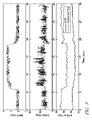
- FIG. 8 illustrates various data plots corresponding to a desired combustion phasing at different steady state engine loads and transitions therebetween for engine operation without external EGR;
- FIG. 9 illustrates various data plots corresponding to a desired combustion phasing at different steady state engine loads and transitions therebetween for engine operation with external EGR.
- numeral 10 generally indicates a schematic representation of an exemplary single-cylinder direct-injection four-stroke internal combustion engine.
- a piston 11 is movable in a cylinder 12 and defines with the cylinder 12 a variable volume combustion chamber 13 .
- An intake passage 14 supplies air into the combustion chamber 13 . Air flow into the combustion chamber 13 is controlled by an intake valve 15 . Combusted gases can flow from the combustion chamber 13 via an exhaust passage 16 , controlled by an exhaust valve 17 .
- Exemplary engine 10 has a hydraulically controlled valve train with an electronic controller 18 , which is programmable and hydraulically controls the opening and closing of both the intake 15 and exhaust 17 valves.
- the electronic controller 18 will control the movement of the intake valve 15 and exhaust valve 17 having regard to the positions of the intake and exhaust valves 15 and 17 as measured by two position transducers 19 and 20 .
- Such a hydraulically controlled valve system is generally considered fully flexible with respect to establishing desired valve profiles in lift, duration and phase.
- Alternative valve train mechanizations including, for example, multi-step cams and independent intake/exhaust phasers are also known for effecting the in-cylinder conditions conducive to HCCI operation.
- the controller 18 will also refer to the angular position of the engine, as indicated by a rotation sensor 21 connected to the engine crankshaft 22 .
- various other sensors may be employed in the engine controls as known to one skilled in the art, including non-exhaustive examples of engine exhaust gas temperature, exhaust gas constituents sensors, mass air flow, manifold/ambient pressure and temperature.
- the crankshaft 22 is connected by a connecting rod 23 to the piston 11 reciprocating in the cylinder 12 .
- a gasoline direct injector 24 controlled by the electronic controller 18 , is used to inject fuel directly into the combustion chamber 13 .
- the various functions ascribed to the controller 18 may equally well be performed by a plurality of separate but coordinated controllers adapted for the various tasks.
- a spark plug 25 controlled also by the electronic controller 18 , is used to enhance the ignition timing control of the engine at certain conditions (e.g. during cold start and near the low load operation limit). Also, it has proven preferable to rely on spark ignition near the high part-load operation limit under controlled auto-ignition combustion and during high speed/load operating conditions with throttled or non-throttled SI operation.
- the engine is designed to operate on fuel injected gasoline or similar blends, unthrottled with HCCI combustion over an extended range of engine speeds and loads, which may include engine starting where possible.
- spark ignition and throttle controlled operation may be utilized with conventional or modified control methods under conditions not conducive to HCCI operation and to obtain maximum engine power.
- Applicable fueling strategies may including direct cylinder injection, port fuel injection or throttle body fuel injection. Widely available grades of gasoline and light ethanol blends thereof are preferred fuels; however, alternative liquid and gaseous fuels such as higher ethanol blends (e.g. E80, E85), neat ethanol (E99), neat methanol (M100), natural gas, hydrogen, biogas, various reformates, syngases etc. may also be used in the implementation of the present invention.
- the control system and method described herein below pertains particularly to an engine operated with HCCI combustion that may include a spark ignition backup.
- the combustion control system includes one or more computers or controllers adapted to carry out a repetitive series of steps or functions in a method of combustion control according to the invention.
- FIG. 2 shows a schematic diagram of an engine controller 40 with which robust controlled auto-ignition combustion is achieved during steady state and transient operation.
- the controller 40 includes a feed forward control 42 and a feedback control 44 , connected with associated components of a representative gasoline direct-injection engine 46 .
- the feed forward control 42 achieves a fast system response. Based on the desired load and engine operating mode conditions, required fuel injection timings (FI) and pulse widths (fueling rate) 48 , valve actuation (including negative valve overlap (NVO)) 50 , spark timing (SI) 52 , throttle position 54 , and EGR valve position 56 are calculated from look-up tables 57 to control the combustion phasing. Also, depending on the current engine operating conditions and driver's load demand, variable rate limiters 58 , 60 , 62 , 64 , 66 are used to compensate different dynamics in the system, e.g., air and fuel dynamics.
- inputs to the engine including at least spark timing (SI), fuel injection timing (FI) and valve timing (and, where used, throttle position and EGR valve position) are set equal to (i.e. synchronized with) steady state inputs corresponding to the current fueling rate.
- SI spark timing
- FI fuel injection timing
- valve timing and, where used, throttle position and EGR valve position
- Pre-calibrated steady state inputs are stored in the look-up tables 57 , and the engine inputs are determined by interpolating values of steady state inputs in the look-up tables.
- the feedforward controller 42 is designed based on extensive calibrations to ensure a successful HCCI combustion under steady state operating conditions.
- the phasing of combustion can suffer from disturbances and/or environmental changes. Disturbances include, for example, significant or rapid changes in engine speed and load, which are necessary occurrences in vehicle engine operation.
- the present invention provides a systematic method or guide-line to effectively calibrate the set-point, and reduces reliance on feedback control for robust transient performance.
- EVC Exhaust Valve Closing
- IVO Intake Valve Opening
- valve motion from either exhaust recompression strategy or exhaust re-breathing strategy
- the partial pressures of the intake charge and the exhaust gas trapped in the cylinder by the valve motion remain constant.
- the gas exchange process model focuses on the cylinder charge temperature after the gas exchange process.
- the cylinder charge temperature at IVC (T ivc ) for the next combustion cycle can be algebraically modeled based on (A.2), (A.4), energy balance and the ideal gas law in accordance with the following relationships:
- T ivc p i ⁇ T int ⁇ T exh p ip ⁇ T exh + p ep ⁇ T int ( 1 )
- p i p ip + p ep ( 2 )
- T int is the intake temperature
- p i is the intake manifold pressure
- p ip is the partial pressure of the intake charge
- p ep is the partial pressure of the exhaust gas trapped in the cylinder.
- FIG. 3 shows a typical curve from the gas exchange process model that shows the relationship between exhaust gas temperature (T exh ) and cylinder charge temperature at IVC (T ivc ) at the next engine cycle given a fixed valve profile. Correlation of combustion exhaust gas temperature (T exh ) and cylinder charge temperature at IVC (T ivc ) is represented by the solid curve GEM. It should be noticed that T ivc monotonically increases as the exhaust gas temperature increases, and it is upper bounded in accordance with the following relationship:
- T ivc ⁇ T ivc max p i p ip ⁇ T int ( 3 )
- AERR Average Energy Release Rate
- T AVE the average combustion temperature during combustion.
- the delivery ratio is defined as the mass of fresh air inducted over the mass of air that would fill displacement volume at the intake manifold pressure and temperature. It is assumed that HCCI combustion begins at the combustion TDC, where the cylinder temperature and pressure reach their maximum values before a spontaneous combustion occurs, and that the average combustion temperature (T AVE ) is approximated in accordance with the following relationship:
- T AVE T TDC + T EOC 2 ( 5 )
- T TDC and T EOC are temperatures at the combustion TDC and the end of combustion, respectively.
- T TDC and T EOC can be derived from the limited-pressure engine cycle in accordance with the following relationships:
- T TDC T IVC ⁇ r r - 1
- the blow-down gas temperature at the exhaust valve opening, T bd can be obtained in accordance with the following relationship from the limited-pressure engine cycle:
- T bd ⁇ ⁇ ( p e p i ) ⁇ - 1 ⁇ ⁇ ( 1 1 - ⁇ + ⁇ ⁇ ⁇ ⁇ ) 1 ⁇ ⁇ ( 1 + ⁇ ⁇ ⁇ r 1 - ⁇ ) 1 ⁇ ⁇ T ivc ( 7 )
- the exhaust gas temperature is modeled in accordance with the following relationship considering the heat transferred to the cylinder wall: T exh + ⁇ T bd +(1 ⁇ ) T w (8)
- T w is the cylinder wall temperature
- ⁇ is a calibratable parameter as a function of operating conditions such as engine speed, charge temperature, etc.
- AERR AERR model
- engine speed and fueling rate were varied from 1000 to 2000 rpm and 7 to 18 mg/cycle, respectively, and the air-fuel ratio was varied from stoichiometry to 30:1.
- AERR can be determined in accordance with the following relationship:
- FIG. 4 shows the calculated AERR from Eq. (4) and the AERR calculated using Eq. (9) based on the heat release analysis of the experimental data.
- FIG. 4 shows that the AERR predicted by the model matches the AERR from the experimental data within a reasonable accuracy.
- FIG. 5 shows typical results of the HCCI combustion process model that illustrates the relationship between the cylinder charge temperature at IVC (T ivc ) and the exhaust gas temperature (T exh ) after HCCI combustion with fixed valve profiles and hence the gas exchange process.
- the dashed curves illustrate the relationship between the cylinder charge temperature at IVC and the exhaust gas temperature after HCCI combustion with constant ⁇ , or equivalently, constant combustion duration.
- the dashed curves therefore, are lines of constant combustion duration.
- FIG. 6 shows temperature curves GEM, CM correlating T ivc and T exh as calculated from the gas exchange process model and the combustion process model, respectively, when the fueling rate is fixed at 11 mg/cycle with no external EGR, 90 deg C. intake temperature, engine speed equal to 1000 rpm, and with air-fuel ratios equal to 20:1 and 26:1, respectively.
- Thermal equilibrium points can be obtained at the junction of the two respective curves, GEM and CM, from the gas exchange process and combustion process models. Stability of the equilibrium point can be checked by building a trajectory of the exhaust gas temperature following those curves as shown in the FIG. 6 .
- FIG. 6 shows, for example, that the resulting equilibrium point with air-fuel ratio equal to 20:1 is asymptotically stable, while that of air-fuel ratio equal to 26:1 could be either asymptotically stable or a center of stable limit cycle.
- combustion duration becomes extremely sensitive to T ivc as ⁇ increases, indicating that sensitivity of combustion duration over T ivc is closely related to how long the combustion duration is. Based on this observation, the sensitivity of auto-ignited combustion in HCCI engine can be investigated by examining sensitivity of ⁇ of those thermal equilibrium points from the model under various operating conditions.
- FIG. 7 shows thermal equilibrium curves obtained from the model with fueling rate equal to 11 mg/cycle at 1000 rpm, with constant intake temperature at 90 deg C., with no external EGR (curve 601 ) and with 4% of external EGR (curve 603 ).
- the figure also illustrates the equilibrium points when the valve profile is fixed at either one of two settings (corresponding to GEM 1 and GEM 2 ) so that partial pressure of intake charge remains the same at 48.3 kPa and 31.6 kPa, respectively, regardless of external EGR.
- FIG. 7 shows that combustion duration, and hence combustion phasing (e.g. CA50), in general increases (i.e. increasing ⁇ ) with increasing external EGR.
- FIG. CA50 combustion duration, and hence combustion phasing
- two load transient experiments were performed with a multi-cylinder HCCI engine.
- the engine was operated with exhaust recompression strategy at engine speed of 2000 rpm, and the fueling rate was changed from 7 mg/cycle to 11 mg/cycle.
- the engine on the experiments was operated unthrottled with HCCI combustion and included operating the engine with predetermined values of external EGR, internal EGR settings, and burned gas fraction set points for intake and exhaust gases.
- a closed-loop control implemented repeated adjustments to the external EGR and internal EGR settings to move the exhaust and intake gases burned gas fractions toward their set points.
- the desired values of combustion phasing indicated by 50% of fuel-burn point in crank-angle (CA50), were set to be 7 deg ATDC at 7 mg/cycle of fuel and 9 deg ATDC at 11 mg/cycle of fuel, respectively.
- desired values of air-fuel ratio were set to be 18.5 at 7 mg/cycle of fuel and 16 at 1 mg/cycle of fuel, respectively, so that the desired combustion phasing can be achieved without external EGR in steady state at either 7 mg/cycle or 1 mg/cycle of fuel.
- the experimental result is shown in FIG. 8 .
- FIG. 8 shows that there were misfires/partial-burns during tip-in, while combustion was successfully maintained during tip-out. This indicates that combustion at chosen set-points is not robust to disturbances during transient, even though combustion is very stable in steady state.
- desired values of air-fuel ratio were set to be 16 at 7 mg/cycle of fuel and 15 at 11 mg/cycle of fuel, respectively, so that the desired combustion phasing (7 deg ATDC and 9 deg ATDC respectively) can be achieved with external EGR in steady state at either 7 mg/cycle or 11 mg/cycle of fuel.
- FIG. 9 shows that there were no misfires/partial-burns during either tip-in or tip-out. This indicates that combustion at the chosen set-points is robust to disturbances during transient, in contrast to the first experiment.
Landscapes
- Engineering & Computer Science (AREA)
- Chemical & Material Sciences (AREA)
- Combustion & Propulsion (AREA)
- Mechanical Engineering (AREA)
- General Engineering & Computer Science (AREA)
- Output Control And Ontrol Of Special Type Engine (AREA)
- Electrical Control Of Air Or Fuel Supplied To Internal-Combustion Engine (AREA)
Abstract
Description
VIVC is the cylinder volume at IVC, VEOC is the cylinder volume at the end of combustion, mf is a given fuel mass, and QLHV is the low heating value of the fuel. Since it is assumed that combustion begins at the combustion TDC, β is proportional to combustion duration. The blow-down gas temperature at the exhaust valve opening, Tbd, can be obtained in accordance with the following relationship from the limited-pressure engine cycle:
T exh +αT bd+(1−α)T w (8)
Claims (12)
Priority Applications (1)
| Application Number | Priority Date | Filing Date | Title |
|---|---|---|---|
| US11/739,142 US7409285B2 (en) | 2006-04-24 | 2007-04-24 | Homogeneous charge compression ignition engine operation |
Applications Claiming Priority (2)
| Application Number | Priority Date | Filing Date | Title |
|---|---|---|---|
| US79456106P | 2006-04-24 | 2006-04-24 | |
| US11/739,142 US7409285B2 (en) | 2006-04-24 | 2007-04-24 | Homogeneous charge compression ignition engine operation |
Publications (2)
| Publication Number | Publication Date |
|---|---|
| US20070250256A1 US20070250256A1 (en) | 2007-10-25 |
| US7409285B2 true US7409285B2 (en) | 2008-08-05 |
Family
ID=38656316
Family Applications (1)
| Application Number | Title | Priority Date | Filing Date |
|---|---|---|---|
| US11/739,142 Expired - Fee Related US7409285B2 (en) | 2006-04-24 | 2007-04-24 | Homogeneous charge compression ignition engine operation |
Country Status (4)
| Country | Link |
|---|---|
| US (1) | US7409285B2 (en) |
| CN (1) | CN101427258B (en) |
| DE (1) | DE112007000984B4 (en) |
| WO (1) | WO2007127707A2 (en) |
Cited By (6)
| Publication number | Priority date | Publication date | Assignee | Title |
|---|---|---|---|---|
| US20110288747A1 (en) * | 2010-05-24 | 2011-11-24 | GM Global Technology Operations LLC | Method and apparatus for operating an internal combustion engine in a homogeneous-charge compression-ignition combustion mode |
| US8616182B2 (en) | 2010-05-24 | 2013-12-31 | GM Global Technology Operations LLC | Method and apparatus for controlling an internal combustion engine coupled to a passive selective catalytic reduction aftertreatment system |
| US8918265B2 (en) | 2012-01-18 | 2014-12-23 | GM Global Technology Operations LLC | Method and apparatus for controlling operation of an internal combustion engine operating in HCCI combustion mode |
| US9008944B2 (en) | 2010-05-24 | 2015-04-14 | GM Global Technology Operations LLC | Method and apparatus for controlling operation of an internal combustion engine operating in HCCI combustion mode |
| US9453481B2 (en) | 2013-06-04 | 2016-09-27 | Ford Global Technologies, Llc | System and method for operating an engine |
| US9689336B2 (en) | 2014-11-10 | 2017-06-27 | Caterpillar Inc. | Engine system utilizing modal weighted engine optimization |
Families Citing this family (11)
| Publication number | Priority date | Publication date | Assignee | Title |
|---|---|---|---|---|
| US7475671B1 (en) * | 2007-12-21 | 2009-01-13 | Delphi Technologies, Inc. | Method for compensating injection timing during transient response of pre-mixed combustion |
| US7506535B2 (en) * | 2007-04-24 | 2009-03-24 | Gm Global Technology Operations, Inc. | Method and apparatus for determining a combustion parameter for an internal combustion engine |
| EP2570634B1 (en) * | 2010-05-10 | 2014-11-05 | Toyota Jidosha Kabushiki Kaisha | Control device for internal combustion engine |
| US9038579B2 (en) * | 2011-05-11 | 2015-05-26 | Korea Institute Of Machinery & Materials | Fuel cell-engine hybrid system |
| US9284906B2 (en) * | 2011-06-08 | 2016-03-15 | GM Global Technology Operations LLC | Combustion phasing control methodology in HCCI combustion |
| US9267451B2 (en) * | 2011-09-27 | 2016-02-23 | GM Global Technology Operations LLC | Method and apparatus for controlling combustion noise in an internal combustion engine |
| AT516289B1 (en) * | 2014-10-06 | 2016-07-15 | Ge Jenbacher Gmbh & Co Og | Method for operating an auto-ignition internal combustion engine |
| CN104656443B (en) * | 2014-12-31 | 2017-05-24 | 重庆邮电大学 | HCCI engine ignition timing self-adaptive PID control method based on BP neural network |
| US20200024536A1 (en) | 2018-07-20 | 2020-01-23 | Afton Chemical Corporation | Fuel-Soluble Synergistic Cleaning Mixture for High Pressure Gasoline Engines |
| US11390821B2 (en) | 2019-01-31 | 2022-07-19 | Afton Chemical Corporation | Fuel additive mixture providing rapid injector clean-up in high pressure gasoline engines |
| EP3825387A1 (en) | 2019-11-22 | 2021-05-26 | Afton Chemical Corporation | Fuel-soluble cavitation inhibitor for fuels used in common-rail injection engines |
Citations (5)
| Publication number | Priority date | Publication date | Assignee | Title |
|---|---|---|---|---|
| US6230694B1 (en) * | 1998-05-26 | 2001-05-15 | Siemens Canada, Ltd. | Calibration and testing of an automotive emission control module |
| US20020078918A1 (en) | 2000-12-26 | 2002-06-27 | Richard Ancimer | Method and apparatus for gaseous fuel introduction and controlling combustion in an internal combustion engine |
| US20030066498A1 (en) | 2001-10-04 | 2003-04-10 | Evan Guy Enterprises, Inc. | Method and apparatus for reducing emissions of internal combustion engines |
| US6874360B1 (en) * | 2003-09-23 | 2005-04-05 | Delphi Technologies, Inc. | Method of determining rubbing friction torque in a motor vehicle powertrain |
| US20060016438A1 (en) | 2004-07-21 | 2006-01-26 | Jun-Mo Kang | HCCI engine combustion control |
Family Cites Families (4)
| Publication number | Priority date | Publication date | Assignee | Title |
|---|---|---|---|---|
| EP1320675B1 (en) * | 2000-02-11 | 2005-12-14 | Westport Research Inc. | Method and apparatus for gaseous fuel introduction and controlling combustion in an internal combustion engine |
| AT5646U1 (en) * | 2001-08-27 | 2002-09-25 | Avl List Gmbh | METHOD FOR OPERATING AN INTERNAL COMBUSTION ENGINE |
| AT5300U1 (en) * | 2001-09-06 | 2002-05-27 | Avl List Gmbh | METHOD FOR OPERATING AN INTERNAL COMBUSTION ENGINE |
| AT5217U1 (en) * | 2001-09-28 | 2002-04-25 | Avl List Gmbh | METHOD FOR CONTROLLED OPERATION OF AN INTERNAL COMBUSTION ENGINE |
-
2007
- 2007-04-24 CN CN200780014711.2A patent/CN101427258B/en not_active Expired - Fee Related
- 2007-04-24 WO PCT/US2007/067261 patent/WO2007127707A2/en not_active Ceased
- 2007-04-24 DE DE112007000984.5T patent/DE112007000984B4/en not_active Expired - Fee Related
- 2007-04-24 US US11/739,142 patent/US7409285B2/en not_active Expired - Fee Related
Patent Citations (5)
| Publication number | Priority date | Publication date | Assignee | Title |
|---|---|---|---|---|
| US6230694B1 (en) * | 1998-05-26 | 2001-05-15 | Siemens Canada, Ltd. | Calibration and testing of an automotive emission control module |
| US20020078918A1 (en) | 2000-12-26 | 2002-06-27 | Richard Ancimer | Method and apparatus for gaseous fuel introduction and controlling combustion in an internal combustion engine |
| US20030066498A1 (en) | 2001-10-04 | 2003-04-10 | Evan Guy Enterprises, Inc. | Method and apparatus for reducing emissions of internal combustion engines |
| US6874360B1 (en) * | 2003-09-23 | 2005-04-05 | Delphi Technologies, Inc. | Method of determining rubbing friction torque in a motor vehicle powertrain |
| US20060016438A1 (en) | 2004-07-21 | 2006-01-26 | Jun-Mo Kang | HCCI engine combustion control |
Non-Patent Citations (2)
| Title |
|---|
| C. J. Chiang and A.G. Stefanopoulou, "Steady-State Multiplicity and Stability of Thermal Equilibria in Homogeneous Charge Compression Ignition (HCCI) Engines", IEEE Proceedings of 2004 Conference in Decision and Control, U.S.A. |
| P. Najt, D. Foster, "Compression-Ignition Homogeneous Charge", SAE paper 830264, Detroit, MI. |
Cited By (9)
| Publication number | Priority date | Publication date | Assignee | Title |
|---|---|---|---|---|
| US20110288747A1 (en) * | 2010-05-24 | 2011-11-24 | GM Global Technology Operations LLC | Method and apparatus for operating an internal combustion engine in a homogeneous-charge compression-ignition combustion mode |
| DE102011102029A1 (en) | 2010-05-24 | 2011-12-08 | Gm Global Technology Operations Llc (N.D.Ges.D. Staates Delaware) | METHOD AND DEVICE FOR OPERATING A COMBUSTION ENGINE IN A BURNING MODE WITH HOMOGENEOUS COMPRESSION IGNITION |
| CN102287259A (en) * | 2010-05-24 | 2011-12-21 | 通用汽车环球科技运作有限责任公司 | Method and apparatus for operating an internal combustion engine in a homogeneous-charge compression-ignition combustion mode |
| US8616182B2 (en) | 2010-05-24 | 2013-12-31 | GM Global Technology Operations LLC | Method and apparatus for controlling an internal combustion engine coupled to a passive selective catalytic reduction aftertreatment system |
| US8645044B2 (en) * | 2010-05-24 | 2014-02-04 | GM Global Technology Operations LLC | Method and apparatus for operating an internal combustion engine in a homogeneous-charge compression-ignition combustion mode |
| US9008944B2 (en) | 2010-05-24 | 2015-04-14 | GM Global Technology Operations LLC | Method and apparatus for controlling operation of an internal combustion engine operating in HCCI combustion mode |
| US8918265B2 (en) | 2012-01-18 | 2014-12-23 | GM Global Technology Operations LLC | Method and apparatus for controlling operation of an internal combustion engine operating in HCCI combustion mode |
| US9453481B2 (en) | 2013-06-04 | 2016-09-27 | Ford Global Technologies, Llc | System and method for operating an engine |
| US9689336B2 (en) | 2014-11-10 | 2017-06-27 | Caterpillar Inc. | Engine system utilizing modal weighted engine optimization |
Also Published As
| Publication number | Publication date |
|---|---|
| CN101427258A (en) | 2009-05-06 |
| DE112007000984B4 (en) | 2015-03-05 |
| DE112007000984T5 (en) | 2009-03-05 |
| US20070250256A1 (en) | 2007-10-25 |
| WO2007127707A2 (en) | 2007-11-08 |
| WO2007127707A3 (en) | 2008-05-02 |
| CN101427258B (en) | 2014-05-14 |
Similar Documents
| Publication | Publication Date | Title |
|---|---|---|
| US7409285B2 (en) | Homogeneous charge compression ignition engine operation | |
| US7540270B2 (en) | Method and apparatus for controlling combustion mode transitions in an internal combustion engine | |
| US7480558B2 (en) | Method and apparatus for controlling a homogeneous charge compression ignition engine | |
| CN101160458B (en) | Method for load transition control between lean and stoichiometric combustion modes of a direct injection engine with controlled auto-ignition combustion | |
| US7360523B2 (en) | Method and apparatus to control operation of a homogeneous charge compression-ignition engine | |
| US8347860B2 (en) | Control strategy for a homogeneous-charge compression-ignition engine | |
| US7689344B2 (en) | Method and apparatus for controlling transitions in an engine having multi-step valve lift | |
| CN101218423B (en) | Method of switching between controlled auto-ignition and spark ignition modes for direct fuel injection engines | |
| CN101680415B (en) | Method and apparatus for enabling control of fuel injection for an engine operating in an auto-ignition mode | |
| CN103016166B (en) | For controlling the method and apparatus of combustion noise in explosive motor | |
| CN101970846B (en) | Method for monitoring an egr valve in an internal combustion engine | |
| US8235012B2 (en) | Method for controlling combustion mode transitions in an internal combustion engine | |
| US8195375B2 (en) | Method for controlling combustion mode transitions in an internal combustion engine | |
| US7966991B2 (en) | Method and apparatus for controlling combustion mode transitions in an internal combustion engine | |
| US9803580B2 (en) | Method and apparatus for controlling operation of an internal combustion engine | |
| US7975672B2 (en) | Method for controlling engine intake airflow | |
| US8229648B2 (en) | Method and apparatus for controlling fuel injection in a homogeneous charge compression ignition engine | |
| CN103032180B (en) | Method for combustion mode transition |
Legal Events
| Date | Code | Title | Description |
|---|---|---|---|
| AS | Assignment |
Owner name: GM GLOBAL TECHNOLOGY OPERATIONS, INC., MICHIGAN Free format text: ASSIGNMENT OF ASSIGNORS INTEREST;ASSIGNORS:KANG, JUN-MO;CHANG, CHEN-FANG;CHANG, MAN-FENG;AND OTHERS;REEL/FRAME:019647/0256;SIGNING DATES FROM 20070430 TO 20070501 |
|
| STCF | Information on status: patent grant |
Free format text: PATENTED CASE |
|
| AS | Assignment |
Owner name: UNITED STATES DEPARTMENT OF THE TREASURY, DISTRICT Free format text: SECURITY AGREEMENT;ASSIGNOR:GM GLOBAL TECHNOLOGY OPERATIONS, INC.;REEL/FRAME:022201/0448 Effective date: 20081231 Owner name: UNITED STATES DEPARTMENT OF THE TREASURY,DISTRICT Free format text: SECURITY AGREEMENT;ASSIGNOR:GM GLOBAL TECHNOLOGY OPERATIONS, INC.;REEL/FRAME:022201/0448 Effective date: 20081231 |
|
| AS | Assignment |
Owner name: CITICORP USA, INC. AS AGENT FOR BANK PRIORITY SECU Free format text: SECURITY AGREEMENT;ASSIGNOR:GM GLOBAL TECHNOLOGY OPERATIONS, INC.;REEL/FRAME:022553/0540 Effective date: 20090409 Owner name: CITICORP USA, INC. AS AGENT FOR HEDGE PRIORITY SEC Free format text: SECURITY AGREEMENT;ASSIGNOR:GM GLOBAL TECHNOLOGY OPERATIONS, INC.;REEL/FRAME:022553/0540 Effective date: 20090409 |
|
| AS | Assignment |
Owner name: GM GLOBAL TECHNOLOGY OPERATIONS, INC., MICHIGAN Free format text: RELEASE BY SECURED PARTY;ASSIGNOR:UNITED STATES DEPARTMENT OF THE TREASURY;REEL/FRAME:023124/0563 Effective date: 20090709 Owner name: GM GLOBAL TECHNOLOGY OPERATIONS, INC.,MICHIGAN Free format text: RELEASE BY SECURED PARTY;ASSIGNOR:UNITED STATES DEPARTMENT OF THE TREASURY;REEL/FRAME:023124/0563 Effective date: 20090709 |
|
| AS | Assignment |
Owner name: GM GLOBAL TECHNOLOGY OPERATIONS, INC., MICHIGAN Free format text: RELEASE BY SECURED PARTY;ASSIGNORS:CITICORP USA, INC. AS AGENT FOR BANK PRIORITY SECURED PARTIES;CITICORP USA, INC. AS AGENT FOR HEDGE PRIORITY SECURED PARTIES;REEL/FRAME:023155/0663 Effective date: 20090814 Owner name: GM GLOBAL TECHNOLOGY OPERATIONS, INC.,MICHIGAN Free format text: RELEASE BY SECURED PARTY;ASSIGNORS:CITICORP USA, INC. AS AGENT FOR BANK PRIORITY SECURED PARTIES;CITICORP USA, INC. AS AGENT FOR HEDGE PRIORITY SECURED PARTIES;REEL/FRAME:023155/0663 Effective date: 20090814 |
|
| AS | Assignment |
Owner name: UNITED STATES DEPARTMENT OF THE TREASURY, DISTRICT Free format text: SECURITY AGREEMENT;ASSIGNOR:GM GLOBAL TECHNOLOGY OPERATIONS, INC.;REEL/FRAME:023156/0264 Effective date: 20090710 Owner name: UNITED STATES DEPARTMENT OF THE TREASURY,DISTRICT Free format text: SECURITY AGREEMENT;ASSIGNOR:GM GLOBAL TECHNOLOGY OPERATIONS, INC.;REEL/FRAME:023156/0264 Effective date: 20090710 |
|
| AS | Assignment |
Owner name: UAW RETIREE MEDICAL BENEFITS TRUST, MICHIGAN Free format text: SECURITY AGREEMENT;ASSIGNOR:GM GLOBAL TECHNOLOGY OPERATIONS, INC.;REEL/FRAME:023162/0140 Effective date: 20090710 Owner name: UAW RETIREE MEDICAL BENEFITS TRUST,MICHIGAN Free format text: SECURITY AGREEMENT;ASSIGNOR:GM GLOBAL TECHNOLOGY OPERATIONS, INC.;REEL/FRAME:023162/0140 Effective date: 20090710 |
|
| AS | Assignment |
Owner name: GM GLOBAL TECHNOLOGY OPERATIONS, INC., MICHIGAN Free format text: RELEASE BY SECURED PARTY;ASSIGNOR:UNITED STATES DEPARTMENT OF THE TREASURY;REEL/FRAME:025245/0656 Effective date: 20100420 |
|
| AS | Assignment |
Owner name: GM GLOBAL TECHNOLOGY OPERATIONS, INC., MICHIGAN Free format text: RELEASE BY SECURED PARTY;ASSIGNOR:UAW RETIREE MEDICAL BENEFITS TRUST;REEL/FRAME:025314/0946 Effective date: 20101026 |
|
| AS | Assignment |
Owner name: WILMINGTON TRUST COMPANY, DELAWARE Free format text: SECURITY AGREEMENT;ASSIGNOR:GM GLOBAL TECHNOLOGY OPERATIONS, INC.;REEL/FRAME:025324/0057 Effective date: 20101027 |
|
| AS | Assignment |
Owner name: GM GLOBAL TECHNOLOGY OPERATIONS LLC, MICHIGAN Free format text: CHANGE OF NAME;ASSIGNOR:GM GLOBAL TECHNOLOGY OPERATIONS, INC.;REEL/FRAME:025781/0035 Effective date: 20101202 |
|
| FPAY | Fee payment |
Year of fee payment: 4 |
|
| AS | Assignment |
Owner name: GM GLOBAL TECHNOLOGY OPERATIONS LLC, MICHIGAN Free format text: RELEASE BY SECURED PARTY;ASSIGNOR:WILMINGTON TRUST COMPANY;REEL/FRAME:034185/0587 Effective date: 20141017 |
|
| FPAY | Fee payment |
Year of fee payment: 8 |
|
| FEPP | Fee payment procedure |
Free format text: MAINTENANCE FEE REMINDER MAILED (ORIGINAL EVENT CODE: REM.); ENTITY STATUS OF PATENT OWNER: LARGE ENTITY |
|
| LAPS | Lapse for failure to pay maintenance fees |
Free format text: PATENT EXPIRED FOR FAILURE TO PAY MAINTENANCE FEES (ORIGINAL EVENT CODE: EXP.); ENTITY STATUS OF PATENT OWNER: LARGE ENTITY |
|
| STCH | Information on status: patent discontinuation |
Free format text: PATENT EXPIRED DUE TO NONPAYMENT OF MAINTENANCE FEES UNDER 37 CFR 1.362 |
|
| FP | Lapsed due to failure to pay maintenance fee |
Effective date: 20200805 |