US7403353B2 - Magnetic recording and reproducing system with recording layer having predetermined convex-concave pattern - Google Patents
Magnetic recording and reproducing system with recording layer having predetermined convex-concave pattern Download PDFInfo
- Publication number
- US7403353B2 US7403353B2 US11/333,505 US33350506A US7403353B2 US 7403353 B2 US7403353 B2 US 7403353B2 US 33350506 A US33350506 A US 33350506A US 7403353 B2 US7403353 B2 US 7403353B2
- Authority
- US
- United States
- Prior art keywords
- burst
- magnetic recording
- convex
- track
- width direction
- Prior art date
- Legal status (The legal status is an assumption and is not a legal conclusion. Google has not performed a legal analysis and makes no representation as to the accuracy of the status listed.)
- Expired - Fee Related, expires
Links
Images


Classifications
-
- G—PHYSICS
- G11—INFORMATION STORAGE
- G11B—INFORMATION STORAGE BASED ON RELATIVE MOVEMENT BETWEEN RECORD CARRIER AND TRANSDUCER
- G11B5/00—Recording by magnetisation or demagnetisation of a record carrier; Reproducing by magnetic means; Record carriers therefor
- G11B5/74—Record carriers characterised by the form, e.g. sheet shaped to wrap around a drum
- G11B5/82—Disk carriers
-
- B—PERFORMING OPERATIONS; TRANSPORTING
- B82—NANOTECHNOLOGY
- B82Y—SPECIFIC USES OR APPLICATIONS OF NANOSTRUCTURES; MEASUREMENT OR ANALYSIS OF NANOSTRUCTURES; MANUFACTURE OR TREATMENT OF NANOSTRUCTURES
- B82Y10/00—Nanotechnology for information processing, storage or transmission, e.g. quantum computing or single electron logic
-
- G—PHYSICS
- G11—INFORMATION STORAGE
- G11B—INFORMATION STORAGE BASED ON RELATIVE MOVEMENT BETWEEN RECORD CARRIER AND TRANSDUCER
- G11B5/00—Recording by magnetisation or demagnetisation of a record carrier; Reproducing by magnetic means; Record carriers therefor
- G11B5/74—Record carriers characterised by the form, e.g. sheet shaped to wrap around a drum
- G11B5/743—Patterned record carriers, wherein the magnetic recording layer is patterned into magnetic isolated data islands, e.g. discrete tracks
-
- G—PHYSICS
- G11—INFORMATION STORAGE
- G11B—INFORMATION STORAGE BASED ON RELATIVE MOVEMENT BETWEEN RECORD CARRIER AND TRANSDUCER
- G11B5/00—Recording by magnetisation or demagnetisation of a record carrier; Reproducing by magnetic means; Record carriers therefor
- G11B5/84—Processes or apparatus specially adapted for manufacturing record carriers
- G11B5/855—Coating only part of a support with a magnetic layer
Definitions
- the present invention relates to a magnetic recording/reproducing system comprising a magnetic recording medium having a magnetic recording layer in a predetermined concave-convex pattern on a substrate and, hence, so-called serve areas and information data areas (a discrete type magnetic recording medium), and a magnetic head operable to detect servo signals on the medium and record and reproduce information data on and from the medium.
- JP(A)11-328662 shows a magnetic recording medium in which a single-layer perpendicular magnetic layer is formed along a concave-convex pattern pre-formed on a substrate.
- JP(A)10-222944 shows a recording medium having a concave-convex configuration varying in its track width direction so as to obtain the stability on levitation of a magnetic head.
- JP(A)2000-195042 comes up with a magnetic recording medium of the discrete type wherein to ensure the stability on levitation of a magnetic head, a non-magnetic material or other material is filled in convex sites.
- JP(A)6-111502 teaches how to, in a longitudinal recording medium, specify relations between the width of a tracking servo burst pattern by a rectangular concave-convex structure, a track pitch and a reproducing head's read width.
- a magnetic recording medium used with a magnetic disk system has a magnetic head-tracking servo area recorded by a servo track writer.
- the servo area generally includes an ISG (initial signal gain) portion, an SVAM (servo address mark) portion, a gray code portion, a burst portion, and a pad portion, which are in the form of various magnetic patterns for performing their own functions, respectively.
- ISG initial signal gain
- SVAM servo address mark
- the burst portion is normally recorded at about one track pitch of width in the radial direction of the magnetic recording medium.
- Other portions i.e., the ISG portion, the SVAM portion, the gray portion and the pad portion are each normally recorded continuously in the disk radial-direction or continuously over at least a few or more tracks in the disk radial direction.
- the burst portion is a pattern to obtain precise position information that tracks the magnetic head precisely to a track position.
- a pattern for such a burst portion for instance, comprises (1) a set of the first and second bursts provided such that they equally step over a centerline for defining the adjacent track pitches, or (2) one more set of the third and fourth bursts added to the first set and offset from it by a 1/2 track pitch.
- the burst patterns are each a rectangular pattern.
- the rectangular patterns are ideal for obtaining accurate position error signals, yet a lot higher accuracy is required in terms of shape and dimension upon their formation.
- a magnetic recording/reproducing system comprising a discrete medium comprising two pairs (sets) of burst patterns, wherein each burst pattern is configured in a substantially trapezoidal shape (truncated quadrangular pyramid shape) in the track width direction and in the track circumference direction, and the magnetic recording/reproducing system satisfies given relations between W 1 , W 2 , Tp and Wr where W 1 and W 2 are the upper side and the lower side of the trapezoidal shape in the track width direction, which correspond to the surface and the bottom surface of a convex-form magnetic recording layer, respectively, Tp is a data track pitch at a data information recording portion, and Wr is the read width of a magnetic head.
- Tp is a data track pitch at a data information recording portion
- Wr is the read width of a magnetic head.
- the object of the invention according to the first group is to seek protection for that wide range of exploitation.
- the object of the invention is to provide a magnetic recording/reproducing system that incorporates a magnetic recording medium having a burst pattern shape that, even when used in a much wider range of exploitation, is much more reduced in loads on medium fabrication processes yet capable of obtaining far more precise position error signals.
- the object of the invention according to the second group is to provide a magnetic recording/reproducing system that incorporates a magnetic recording medium having a burst pattern shape that, even when a variety of track pitch vs. burst pitch relations are involved, is far much more reduced in loads on medium fabrication processes yet capable of obtaining far more precise position error signals, With the addition of one or more burst patterns, it is possible to make a practical range capable of obtaining far more precise position error signals so wider that the range of flexibility in system designs can be made wider.
- a magnetic recording/reproducing system comprising a magnetic recording medium having a data information recording portion and a servo information portion for tracking, and a magnetic head operable to detect servo information at said servo information portion and record and reproduce data information on and from said data information recording portion, wherein:
- said data information recording portion comprises a data track having a data track pitch Tp
- said servo information portion comprises a magnetic recording layer formed in a given concave-convex pattern
- said servo information portion comprises a burst division on which tracking burst signals are recorded
- said burst division comprises a first burst, a second burst, a third burst and a fourth burst, each comprising a plurality of convex-form magnetic recording layers with the burst signals recorded thereon,
- said first burst and said second burst in pair form are located such that the convex-form magnetic recording layers are formed with centerlines defined at positions mutually offset by two track pitches of distance (2Tp) in a track width direction,
- said third burst and said fourth burst in pair form are located such that the convex-form magnetic recording layers are formed with centerlines defined at positions mutually offset by two track pitches of distance (2Tp) in the track width direction, and said third burst and said fourth burst are located such that the convex-form magnetic recording layers are formed with centerlines defined at positions offset from centerlines of said first burst and said second burst by one track pitch of distance (1Tp),
- said convex-form magnetic layers are each configured in a substantially trapezoidal shape (truncated quadrangular pyramid shape) in the track width direction and in a track circumference direction, respectively, and
- said magnetic recording/reproducing system satisfies the following condition provided that W 1 >Tp: 1.25W2>Wr ⁇ 0.5W2
- W 1 is an upper side of said trapezoidal shape in the track width direction, which corresponds to a surface of said convex-form magnetic recoding layer
- W 2 is a lower side of said trapezoidal shape in the track width direction, which corresponds to a bottom surface of said convex-form magnetic layer
- Tp is a data track pitch at said data information recording portion
- Wr is a read width of said magnetic head.
- a magnetic recording/reproducing system comprising a magnetic recording medium having a data information recording portion and a servo information portion for tracking, and a magnetic head operable to-detect servo information at said servo information portion and record and reproduce data information on and from said data information recording portion, wherein:
- said data information recording portion comprises a data track having a data track pitch Tp
- said servo information portion comprises a magnetic recording layer formed in a given concave-convex pattern
- said servo information portion comprises a burst division on which tracking burst signals are recorded
- said burst division comprises a first burst, a second burst, a third burst and a fourth burst, each comprising a plurality of convex-form magnetic recording layers with the burst signals recorded thereon,
- said first burst and said second burst in pair form are located such that the convex-form magnetic recording layers are formed with centerlines defined at positions mutually offset by a (2/3) track pitch of distance ((2/3)Tp) in a track width direction,
- said third burst and said fourth burst in pair form are located such that the convex-form magnetic recording layers are formed with centerlines defined at positions mutually offset by a (2/3) track pitch of distance ((2/3)Tp) in the track width direction, and said third burst and said fourth burst are located such that the convex-form magnetic recording layers are formed with centerlines defined at positions offset from centerlines of said first burst and said second burst by a (1/3) track pitch of distance ((1/3)Tp),
- said convex-form magnetic layers are each configured in a substantially trapezoidal shape (truncated quadrangular pyramid shape) in the track width direction and in a track circumference direction, respectively, and
- said magnetic recording/reproducing system satisfies the following condition provided that Tp>W 2 : 1.5W2 ⁇ Wr ⁇ 0.5W1 where W 1 is an upper side of said trapezoidal shape in the track width direction, which corresponds to a surface of said convex-form magnetic recoding layer, W 2 is a lower side of said trapezoidal shape in the track width direction, which corresponds to a bottom surface of said convex-form magnetic layer, Tp is a data track pitch at said data information recording portion, and Wr is a read width of said magnetic head.
- the magnetic recording/reproducing system satisfies the following condition: tan 85° ⁇ 2 h /( W 2 ⁇ W 1) ⁇ tan 50° where h is a height from the lower side W 2 of to the upper side W 1 of the convex-form magnetic recording layer.
- the magnetic recording/reproducing system satisfies the following condition: Wr ⁇ 2 Tp ⁇ W where W is a data track width, Wr is the magnetic read width, and Tp is the track pitch.
- a magnetic recording/reproducing system comprising a magnetic recording medium having a data information recording portion and a servo information portion for tracking, and a magnetic head operable to detect servo information at said servo information portion and record and reproduce data information on and from said data information recording portion, wherein:
- said data information recording portion comprises a data track having a data track pitch Tp
- said servo information portion comprises a magnetic recording layer formed in a given concave-convex pattern
- said servo information portion comprises a burst division on which tracking burst signals are recorded
- said burst division comprises a first burst, a second burst, a third burst, a fourth burst, a fifth burst and a sixth burst, each comprising a plurality of convex-form magnetic recording layers with the burst signals recorded thereon,
- said first burst and said second burst in pair form are located such that the convex-form magnetic recording layers are formed with centerlines defined at positions mutually offset by one track pitch of distance (1Tp) in a track width direction,
- said third burst and said fourth burst in pair form are located such that the convex-form magnetic recording layers are formed with centerlines defined at positions mutually offset by one track pitch of distance (1Tp) in the track width direction, and said third burst and said fourth burst are located such that the convex-form magnetic recording layers are formed with centerlines defined at positions offset from centerlines of said first burst and said second burst by a (1/3) track pitch of distance ((1/3)Tp),
- said fifth burst and said sixth burst in pair form are located such that the convex-form magnetic recording layers are formed with centerlines defined at positions mutually offset by one track pitch of distance (1Tp) in the track width direction, and said fifth burst and said sixth burst are located such that the convex-form magnetic recording layers are formed with centerlines defined at positions offset from centerlines of said first burst and said second burst by a (2/3) track pitch of distance ((2/3)Tp),
- said convex-form magnetic layers are each configured in a substantially trapezoidal shape (truncated quadrangular pyramid shape) in the track width direction and in a track circumference direction, respectively, and
- said magnetic recording/reproducing system satisfies the following conditions provided that Tp>W 2 : 2W2>Wr ⁇ 0.5W2 0.5W2 ⁇ W1 where W 1 is an upper side of said trapezoidal shape in the track width direction, which corresponds to a surface of said convex-form magnetic recoding layer, W 2 is a lower side of said trapezoidal shape in the track width direction, which corresponds to a bottom surface of said convex-form magnetic layer, Tp is a data track pitch at said data information recording portion, and Wr is a read width of said magnetic head.
- a magnetic recording/reproducing system comprising a magnetic recording medium having a data information recording portion and a servo information portion for tracking, and a magnetic head operable to detect servo information at said servo information portion and record and reproduce data information on and from said data information recording portion, wherein:
- said data information recording portion comprises a data track having a data track pitch Tp
- said servo information portion comprises a magnetic recording layer formed in a given concave-convex pattern
- said servo information portion comprises a burst division on which tracking burst signals are recorded
- said burst division comprises a first burst, a second burst, a third burst, a fourth burst, a fifth burst and a sixth burst, each comprising a plurality of convex-form magnetic recording layers with the burst signals recorded thereon,
- said first burst and said second burst in pair form are located such that the convex-form magnetic recording layers are formed with centerlines defined at positions mutually offset by one track pitch of distance (1Tp) in a track width direction,
- said third burst and said fourth burst in pair form are located such that the convex-form magnetic recording layers are formed with centerlines defined at positions mutually offset by one track pitch of distance (1Tp) in the track width direction, and said third burst and said fourth burst are located such that the convex-form magnetic recording layers are formed with centerlines defined at positions offset from centerlines of said first burst and said second burst by a (1/3) track pitch of distance ((1/3)Tp),
- said fifth burst and said sixth burst in pair form are located such that the convex-form magnetic recording layers are formed with centerlines defined at positions mutually offset by one track pitch of distance (1Tp) in the track width direction, and said fifth burst and said sixth burst are located such that the convex-form magnetic recording layers are formed with centerlines defined at positions offset from centerlines of said first burst and said second burst by a (2/3) track pitch of distance ((2/3)Tp),
- said convex-form magnetic layers are each configured in a substantially trapezoidal shape (truncated quadrangular pyramid shape) in the track width direction and in a track circumference direction, respectively, and
- said magnetic recording/reproducing system satisfies the following condition provided that Tp ⁇ W 1 : 1.5W1 ⁇ Wr ⁇ 0.333W2 where W 1 is an upper side of said trapezoidal shape in the track width direction, which corresponds to a surface of said convex-form magnetic recoding layer, W 2 is a lower side of said trapezoidal shape in the track width direction, which corresponds to a bottom surface of said convex-form magnetic layer, Tp is a data track pitch at said data information recording portion, and Wr is a read width of said magnetic head.
- a magnetic recording/reproducing system comprising a magnetic recording medium having a data information recording portion and a servo information portion for tracking, and a magnetic head operable to detect servo information at said servo information portion and record and reproduce data information on and from said data information recording portion, wherein:
- said data information recording portion comprises a data track having a data track pitch Tp
- said servo information portion comprises a magnetic recording layer formed in a given concave-convex pattern
- said servo information portion comprises a burst division on which tracking burst signals are recorded
- said burst division comprises a first burst, a second burst, a third burst, a fourth burst, a fifth burst and a sixth burst, each comprising a plurality of convex-form magnetic recording layers with the burst signals recorded thereon,
- said first burst and said second burst in pair form are located such that the convex-form magnetic recording layers are formed with centerlines defined at positions mutually offset by a (3/4) track pitch of distance ((3/4)Tp) in a track width direction,
- said third burst and said fourth burst in pair form are located such that the convex-form magnetic recording layers are formed with centerlines defined at positions mutually offset by a (3/4) track pitch of distance ((3/4)Tp) in the track width direction, and said third burst and said fourth burst are located such that the convex-form magnetic recording layers are formed with centerlines defined at positions offset from centerlines of said first burst and said second burst by a (1/4) track pitch of distance ((1/4)Tp),
- said fifth burst and said sixth burst in pair form are located such that the convex-form magnetic recording layers are formed with centerlines defined at positions mutually offset by a (3/4) track pitch of distance ((3/4)Tp) in the track width direction, and said fifth burst and said sixth burst are located such that the convex-form magnetic recording layers are formed with centerlines defined at positions offset from centerlines of said first burst and said second burst by a (1/2) track pitch of distance ((1/2)Tp),
- said convex-form magnetic layers are each configured in a substantially trapezoidal shape (truncated quadrangular pyramid shape) in the track width direction and in a track circumference direction, respectively, and
- said magnetic recording/reproducing system satisfies the following condition provided that Tp>W 2 : 1.5W2 ⁇ Wr ⁇ 0.5W1 where W 1 is an upper side of said trapezoidal shape in the track width direction, which corresponds to a surface of said convex-form magnetic recoding layer, W 2 is a lower side of said trapezoidal shape in the track width direction, which corresponds to a bottom surface of said convex-form magnetic layer, Tp is a data track pitch at said data information recording portion, and Wr is a read width of said magnetic head.
- a magnetic recording/reproducing system comprising a magnetic recording medium having a data information recording portion and a servo information portion for tracking, and a magnetic head operable to detect servo information at said servo information portion and record and reproduce data information on and from said data information recording portion, wherein:
- said data information recording portion comprises a data track having a data track pitch Tp
- said servo information portion comprises a magnetic recording layer formed in a given concave-convex pattern
- said servo information portion comprises a burst division on which tracking burst signals are recorded
- said burst division comprises a first burst, a second burst, a third burst, a fourth burst, a fifth burst and a sixth burst, each comprising a plurality of convex-form magnetic recording layers with the burst signals recorded thereon,
- said first burst and said second burst in pair form are located such that the convex-form magnetic recording layers are formed with centerlines defined at positions mutually offset by (3/2) track pitches of distance ((3/2)Tp) in a track width direction,
- said third burst and said fourth burst in pair form are located such that the convex-form magnetic recording layers are formed with centerlines defined at positions mutually offset by (3/2) track pitches of distance ((3/2)Tp) in the track width direction, and said third burst and said fourth burst are located such that the convex-form magnetic recording layers are formed with centerlines defined at positions offset from centerlines of said first burst and said second burst by a (1/2) track pitch of distance ((1/2)Tp),
- said fifth burst and said sixth burst in pair form are located such that the convex-form magnetic recording layers are formed with centerlines defined at positions mutually offset by (3/2) track pitches of distance ((3/2)Tp) in the track width direction, and said fifth burst and said sixth burst are located such that the convex-form magnetic recording layers are formed with centerlines defined at positions offset from centerlines of said first burst and said second burst by one track pitch of distance (1Tp),
- said convex-form magnetic layers are each configured in a substantially trapezoidal shape (truncated quadrangular pyramid shape) in the track width direction and in a track circumference direction, respectively, and
- said magnetic recording/reproducing system satisfies the following conditions provided that W 1 >Tp: 1.5W2>Wr ⁇ 0.333W2 0.333W2 ⁇ W1 where W 1 is an upper side of said trapezoidal shape in the track width direction, which corresponds to a surface of said convex-form magnetic recoding layer, W 2 is a lower side of said trapezoidal shape in the track width direction, which corresponds to a bottom surface of said convex-form magnetic layer, Tp is a data track pitch at said data information recording portion, and Wr is a read width of said magnetic head.
- a magnetic recording/reproducing system comprising a magnetic recording medium having a data information recording portion and a servo information portion for tracking, and a magnetic head operable to detect servo information at said servo information portion and record and reproduce data information on and from said data information recording portion, wherein:
- said data information recording portion comprises a data track having a data track pitch Tp
- said servo information portion comprises a magnetic recording layer formed in a given concave-convex pattern
- said servo information portion comprises a burst division on which tracking burst signals are recorded
- said burst division comprises a first burst, a second burst, a third burst, a fourth burst, a fifth burst and a sixth burst, each comprising a plurality of convex-form magnetic recording layers with the burst signals recorded thereon,
- said first burst and said second burst in pair form are located such that the convex-form magnetic recording layers are formed with centerlines defined at positions mutually offset by three track pitches of distance (3Tp) in a track width direction,
- said third burst and said fourth burst in pair form are located such that the convex-form magnetic recording layers are formed with centerlines defined at positions mutually offset by three track pitches of distance (3Tp) in the track width direction, and said third burst and said fourth burst are located such that the convex-form magnetic recording layers are formed with centerlines defined at positions offset from centerlines of said first burst and said second burst by one track pitch of distance (1Tp),
- said fifth burst and said sixth burst in pair form are located such that the convex-form magnetic recording layers are formed with centerlines defined at positions mutually offset by three track pitches of distance (3Tp) in the track width direction, and said fifth burst and said sixth burst are located such that the convex-form magnetic recording layers are formed with centerlines defined at positions offset from centerlines of said first burst and said second burst by two track pitches of distance (2Tp),
- said convex-form magnetic layers are each configured in a substantially trapezoidal shape (truncated quadrangular pyramid shape) in the track width direction and in a track circumference direction, respectively, and
- said magnetic recording/reproducing system satisfies the following conditions provided that W 1 >Tp: 1.5W 2 >Wr ⁇ 0.444W2
- W 1 is an upper side of said trapezoidal shape in the track width direction, which corresponds to a surface of said convex-form magnetic recoding layer
- W 2 is a lower side of said trapezoidal shape in the track width direction, which corresponds to a bottom surface of said convex-form magnetic layer
- Tp is a data track pitch at said data information recording portion
- Wr is a read width of said magnetic head.
- the magnetic recording/reproducing system satisfies the following condition: Wr ⁇ 2 Tp ⁇ W where W is a data track width, Wr is the magnetic read width, and Tp is the track pitch.
- FIG. 1 is illustrative in schematic plan of the whole shape of one disk-shaped magnetic recording medium according to the invention.
- FIG. 2 is an enlarged schematic view of the small area surrounded by a rectangle in FIG. 1 .
- FIG. 3 is a sectional view illustrative in section of one preferred embodiment of the magnetic recording medium of the invention.
- FIG. 4 is a sectional view illustrative in section of another preferred embodiment of the magnetic recording medium of the invention.
- FIG. 5 is illustrative in schematic perspective of the structure of a trapezoidal perpendicular magnetic recording layer.
- FIG. 6 is illustrative in schematic perspective of a magnetic recording/reproducing system.
- FIG. 9 is illustrative of one specific experimentation embodiment, wherein the relations of burst patterns W 1 , W 2 and track pitch Tp to magnetic read width Wr are schematically illustrated together with position error signal PES.
- FIG. 10 is illustrative of another specific experimentation embodiment, wherein the relations of burst patterns W 1 , W 2 and track pitch Tp to magnetic read width Wr are schematically illustrated together with position error signal PES.
- FIG. 11 is illustrative of yet another specific experimentation embodiment, wherein the relations of burst patterns W 1 , W 2 and track pitch Tp to magnetic read width Wr are schematically illustrated together with position error signal PES.
- FIG. 12 is illustrative of a further specific experimentation embodiment, wherein the relations of burst patterns W 1 , W 2 and track pitch Tp to magnetic read width Wr are schematically illustrated together with position error signal PES.
- FIG. 13 is illustrative of a further specific experimentation embodiment, wherein the relations of burst patterns W 1 , W 2 and track pitch Tp to magnetic read width Wr are schematically illustrated together with position error signal PES.
- FIG. 14 is illustrative of a further specific experimentation embodiment, wherein the relations of burst patterns W 1 , W 2 and track pitch Tp to magnetic read width Wr are schematically illustrated together with position error signal PES.
- FIG. 15 is illustrative of a further specific experimentation embodiment, wherein the relations of burst patterns W 1 , W 2 and track pitch Tp to magnetic read width Wr are schematically illustrated together with position error signal PES.
- FIG. 16 is illustrative of a further specific experimentation embodiment, wherein the relations of burst patterns W 1 , W 2 and track pitch Tp to magnetic read width Wr are schematically illustrated together with position error signal PES.
- FIG. 17 is illustrative of a further specific experimentation embodiment, wherein the relations of burst patterns W 1 , W 2 and track pitch Tp to magnetic read width Wr are schematically illustrated together with position error signal PES.
- FIG. 18 is illustrative of a further specific experimentation embodiment, wherein the relations of burst patterns W 1 , W 2 and track pitch Tp to magnetic read width Wr are schematically illustrated together with position error signal PES.
- FIG. 19 is illustrative of a further specific experimentation embodiment, wherein the relations of burst patterns W 1 , W 2 and track pitch Tp to magnetic read width Wr are schematically illustrated together with position error signal PES.
- FIG. 20 is illustrative of one experimentation embodiment carried out for the examination of the dependency on angle of a trapezoidal slant of the trapezoidal pattern.
- FIG. 21 is illustrative of another experimentation embodiment carried out for the examination of the dependency on angle of a trapezoidal slant of the trapezoidal pattern.
- FIG. 22 is illustrative of yet another experimentation embodiment carried out for the examination of the dependency on angle of a trapezoidal slant of the trapezoidal pattern.
- FIG. 23 is illustrative of a further experimentation embodiment carried out for the examination of the dependency on angle of a trapezoidal slant of the trapezoidal pattern.
- FIG. 24 is illustrative of a further experimentation embodiment carried out for the examination of the dependency on angle of a trapezoidal slant of the trapezoidal pattern.
- FIG. 25 is a schematic section taken on A-A′ arrow line in FIG. 9
- FIG. 26 is illustrative of explaining the definition of “read width Wr”.
- FIG. 27 is illustrative of the condition for the upper limit to the magnetic read width Wr.
- FIG. 28 is illustrative in schematic plan of the whole shape of another disk-shaped magnetic recording medium according to the invention.
- FIG. 29 is an enlarged schematic view of the small area surrounded by a rectangle in FIG. 28 .
- FIG. 30 is a sectional view illustrative in section of one preferred embodiment of the magnetic recording medium of the invention.
- FIG. 31 is a sectional view illustrative in section of another preferred embodiment of the magnetic recording medium of the invention.
- FIG. 32 is illustrative in schematic perspective of the structure of a trapezoidal perpendicular magnetic recording layer.
- FIG. 33 is illustrative in schematic perspective of a magnetic recording/reproducing system.
- FIG. 38 is illustrative of a further specific experimentation embodiment, wherein the relations of burst patterns W 1 , W 2 and track pitch Tp to magnetic read width Wr are schematically illustrated together with position error signal PES.
- FIG. 39 is illustrative of a further specific experimentation embodiment, wherein the relations of burst patterns W 1 , W 2 and track pitch Tp to magnetic read width Wr are schematically illustrated together with position error signal PES.
- FIG. 40 is illustrative of a further specific experimentation embodiment, wherein the relations of burst patterns W 1 , W 2 and track pitch Tp to magnetic read width Wr are schematically illustrated together with position error signal PES.
- FIG. 41 is illustrative of a further specific experimentation embodiment, wherein the relations of burst patterns W 1 , W 2 and track pitch Tp to magnetic read width Wr are schematically illustrated together with position error signal PES.
- FIG. 42 is illustrative of a further specific experimentation embodiment, wherein the relations of burst patterns W 1 , W 2 and track pitch Tp to magnetic read width Wr are schematically illustrated together with position error signal PES.
- FIG. 43 is illustrative of a further specific experimentation embodiment, wherein the relations of burst patterns W 1 , W 2 and track pitch Tp to magnetic read width Wr are schematically illustrated together with position error signal PES.
- FIG. 44 is illustrative of a further specific experimentation embodiment, wherein the relations of burst patterns W 1 , W 2 and track pitch Tp to magnetic read width Wr are schematically illustrated together with position error signal PES.
- FIG. 45 is illustrative of a further specific experimentation embodiment, wherein the relations of burst patterns W 1 , W 2 and track pitch Tp to magnetic read width Wr are schematically illustrated together with position error signal PES.
- FIG. 46 is illustrative of a further specific experimentation embodiment, wherein the relations of burst patterns W 1 , W 2 and track pitch Tp to magnetic read width Wr are schematically illustrated together with position error signal PES.
- FIG. 47 is illustrative of a further specific experimentation embodiment, wherein the relations of burst patterns W 1 , W 2 and track pitch Tp to magnetic read width Wr are schematically illustrated together with position error signal PES.
- FIG. 48 is illustrative of a further specific experimentation embodiment, wherein the relations of burst patterns W 1 , W 2 and track pitch Tp to magnetic read width Wr are schematically illustrated together with position error signal PES.
- FIG. 49 is illustrative of a further specific experimentation embodiment, wherein the relations of burst patterns W 1 , W 2 and track pitch Tp to magnetic read width Wr are schematically illustrated together with position error signal PES.
- FIG. 50 is illustrative of a further specific experimentation embodiment, wherein the relations of burst patterns W 1 , W 2 and track pitch Tp to magnetic read width Wr are schematically illustrated together with position error signal PES.
- FIG. 51 is illustrative of a further specific experimentation embodiment, wherein the relations of burst patterns W 1 , W 2 and track pitch Tp to magnetic read width Wr are schematically illustrated together with position error signal PES.
- FIG. 52 is illustrative of a further specific experimentation embodiment, wherein the relations of burst patterns W 1 , W 2 and track pitch Tp to magnetic read width Wr are schematically illustrated together with position error signal PES.
- FIG. 53 is illustrative of a further specific experimentation embodiment, wherein the relations of burst patterns W 1 , W 2 and track pitch Tp to magnetic read width Wr are schematically illustrated together with position error signal PES.
- FIG. 54 is illustrative of a further specific experimentation embodiment, wherein the relations of burst patterns W 1 , W 2 and track pitch Tp to magnetic read width Wr are schematically illustrated together with position error signal PES.
- FIG. 55 is illustrative of a further specific experimentation embodiment, wherein the relations of burst patterns W 1 , W 2 and track pitch Tp to magnetic read width Wr are schematically illustrated together with position error signal PES.
- FIG. 56 is illustrative of a further specific experimentation embodiment, wherein the relations of burst patterns W 1 , W 2 and track pitch Tp to magnetic read width Wr are schematically illustrated together with position error signal PES.
- FIG. 57 is illustrative of a further specific experimentation embodiment, wherein the relations of burst patterns W 1 , W 2 and track pitch Tp to magnetic read width Wr are schematically illustrated together with position error signal PES.
- FIG. 58 is illustrative of a further specific experimentation embodiment, wherein the relations of burst patterns W 1 , W 2 and track pitch Tp to magnetic read width Wr are schematically illustrated together with position error signal PES.
- FIG. 59 is illustrative of a further specific experimentation embodiment, wherein the relations of burst patterns W 1 , W 2 and track pitch Tp to magnetic read width Wr are schematically illustrated together with position error signal PES.
- FIG. 60 is illustrative of a further specific experimentation embodiment, wherein the relations of burst patterns W 1 , W 2 and track pitch Tp to magnetic read width Wr are schematically illustrated together with position error signal PES.
- FIG. 61 is illustrative of a further specific experimentation embodiment, wherein the relations of burst patterns W 1 , W 2 and track pitch Tp to magnetic read width Wr are schematically illustrated together with position error signal PES.
- FIG. 62 is illustrative of a further specific experimentation embodiment, wherein the relations of burst patterns W 1 , W 2 and track pitch Tp to magnetic read width Wr are schematically illustrated together with position error signal PES.
- FIG. 63 is illustrative of a further specific experimentation embodiment, wherein the relations of burst patterns W 1 , W 2 and track pitch Tp to magnetic read width Wr are schematically illustrated together with position error signal PES.
- FIG. 64 is illustrative of a further specific experimentation embodiment, wherein the relations of burst patterns W 1 , W 2 and track pitch Tp to magnetic read width Wr are schematically illustrated together with position error signal PES.
- FIG. 65 is illustrative of a further specific experimentation embodiment, wherein the relations of burst patterns W 1 , W 2 and track pitch Tp to magnetic read width Wr are schematically illustrated together with position error signal PES.
- FIG. 66 is illustrative of a further specific experimentation embodiment, wherein the relations of burst patterns W 1 , W 2 and track pitch Tp to magnetic read width Wr are schematically illustrated together with position error signal PES.
- FIG. 67 is illustrative of a further specific experimentation embodiment, wherein the relations of burst patterns W 1 , W 2 and track pitch Tp to magnetic read width Wr are schematically illustrated together with position error signal PES.
- FIG. 68 is illustrative of a further specific experimentation embodiment, wherein the relations of burst patterns W 1 , W 2 and track pitch Tp to magnetic read width Wr are schematically illustrated together with position error signal PES.
- FIG. 69 is illustrative of a further specific experimentation embodiment, wherein the relations of burst patterns W 1 , W 2 and track pitch Tp to magnetic read width Wr are schematically illustrated together with position error signal PES.
- FIG. 70 is illustrative of a further specific experimentation embodiment, wherein the relations of burst patterns W 1 , W 2 and track pitch Tp to magnetic read width Wr are schematically illustrated together with position error signal PES.
- FIG. 71 is illustrative of a further specific experimentation embodiment, wherein the relations of burst patterns W 1 , W 2 and track pitch Tp to magnetic read width Wr are schematically illustrated together with position error signal PES.
- FIG. 72 is illustrative of a further specific experimentation embodiment, wherein the relations of burst patterns W 1 , W 2 and track pitch Tp to magnetic read width Wr are schematically illustrated together with position error signal PES.
- FIG. 73 is illustrative of a further specific experimentation embodiment, wherein the relations of burst patterns W 1 , W 2 and track pitch Tp to magnetic read width Wr are schematically illustrated together with position error signal PES.
- FIG. 74 is illustrative of a further specific experimentation embodiment, wherein the relations of burst patterns W 1 , W 2 and track pitch Tp to magnetic read width Wr are schematically illustrated together with position error signal PES.
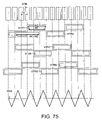
- FIG. 75 is illustrative of a further specific experimentation embodiment, wherein the relations of burst patterns W 1 , W 2 and track pitch Tp to magnetic read width Wr are schematically illustrated together with position error signal PES.
- FIG. 76 is illustrative of a further specific experimentation embodiment, wherein the relations of burst patterns W 1 , W 2 and track pitch Tp to magnetic read width Wr are schematically illustrated together with position error signal PES.
- FIG. 77 is illustrative of a further specific experimentation embodiment, wherein the relations of burst patterns W 1 , W 2 and track pitch Tp to magnetic read width Wr are schematically illustrated together with position error signal PES.
- FIG. 78 is illustrative of one experimentation embodiment carried out for the examination of the dependency on angle of a trapezoidal slant of the trapezoidal pattern.
- FIG. 79 is illustrative of another experimentation embodiment carried out for the examination of the dependency on angle of a trapezoidal slant of the trapezoidal pattern.
- FIG. 80 is illustrative of yet another experimentation embodiment carried out for the examination of the dependency on angle of a trapezoidal slant of the trapezoidal pattern.
- FIG. 81 is illustrative of a further experimentation embodiment carried out for the examination of the dependency on angle of a trapezoidal slant of the trapezoidal pattern.
- FIG. 82 is illustrative of a further experimentation embodiment carried out for the examination of the dependency on angle of a trapezoidal slant of the trapezoidal pattern.
- FIG. 83 is a schematic section taken on A-A′ arrows in FIG. 38
- FIG. 84 is illustrative of giving an account of the definition of “read width Wr”.
- FIG. 85 is illustrative of the condition for the upper limit to the magnetic read width Wr.
- the magnetic recording/reproducing system of the invention is built up of a magnetic recording medium comprising a data information recording portion and a servo information portion for tracking, and a magnetic head operable to detect servo information on the servo information portion and to record and reproduce data information on and from the data information recording portion.
- FIG. 6 is illustrative in schematic perspective of the magnetic recording/reproducing system that is one embodiment of the invention.
- reference numeral 1 stands for a magnetic recording medium for which a disk-shaped perpendicular magnetic recording medium (discrete medium) is used. This medium is rotationally driven by a spindle motor 2 .
- a recording/reproducing magnetic head 5 is attached to the free end of a rotating arm 4 that extends from the outer periphery to the center of the medium.
- the rotating arm 4 is rotated by a voice coil motor 3 so that the magnetic head 5 can be positioned at a given track, for instance, in response to servo signals detected by the recording/reproducing magnetic head 5 .
- the recording/reproducing magnetic head 5 comprises a recording device and a reproducing device.
- a single pole head of the main pole excitation type is used as the recording device, and a GMR (giant magneto-resistance effect) head is used as the reproducing device.
- a GMR (giant magneto-resistance effect) head is used as the reproducing device.
- a TMR (tunneling magneto-resistance effect) head or the like could be used.
- FIG. 1 is illustrative in schematic plan of the whole configuration of a disk-shaped magnetic recording medium 1 used herein
- FIG. 2 is an enlarged schematic view of a small area 100 surrounded by a rectangle in FIG. 1 .
- a serve information portion 90 that is an area with servo signals recorded
- a data information recording portion 80 that is a group of data tracks for recording and reproducing purposes are illustrated in conception.
- FIG. 3 is illustrative in section of a preferred embodiment of the magnetic recording medium according to the invention.
- FIG. 3 is substantially tantamount to a sectional view taken on ⁇ - ⁇ arrows in FIG. 2 .
- a plurality of data track groups for recording and reproducing purposes are concentrically located and formed on a disk substrate.
- a servo signal area (a servo information portion 90 indicated by a radial line) is formed outwardly from the center of the disk. To put it another way, the so-called sector servo arrangement wherein the disk surface is divided into sectors is applied. Servo information is then recorded on the servo information portion 90 of the magnetic recording medium by means of a servo tracking writer.
- the servo information portion (the so-called servo area) comprises an ISG division 91 , an SVAM division 92 , a gray code division 93 , a burst division 94 , and a pad division 95 , as depicted in FIG. 2 .
- the ISG (initial signal gain) division 91 is in the form of a continuous pattern provided for eliminating variations in the magnetic properties of a magnetic film (magnetic layer) in the magnetic recording medium, and the amount of levitation of the magnetic head. That division 91 is continuously formed in the track radial direction. While such ISG division 91 is subjected to reproducing operation by the magnetic head, the gain of a servo demodulation circuit is determined by an automatic gain control (AGC) to implement correction of output variations due to the magnetic recording medium or the magnetic head.
- AGC automatic gain control
- the automatic gain control (AGC) that implements such operation is turned off upon detection of the SVAM (servo address mark) division 92 in the servo area, enabling the reproduction amplitude in the next bust division 94 to be standardized at the amplitude of the ISG division 91 .
- the gray code division 93 has information on each track number and each sector number recorded in it.
- the burst division 94 is a pattern for obtaining precise position information that precisely tracks the magnetic head to a track position. As depicted in FIG. 2 as an example, that pattern comprises a set of a first burst 94 a and a second burst 94 b (in pair form) each equally stepping over a centerline provided at two track pitches of spacing, and a set of a third burst 94 c and a fourth burst 94 b (in pair form) found at a position offset or shifted from the first set by one track pitch of distance.
- the radial length of the first burst 94 a , the second burst 94 b , the third burst 94 c , and the fourth burst 94 d is equal to two tracks of distance.
- the fourth burst 94 d note that, in FIG. 2 , it is shown only with one track of length for reasons of space.
- the first burst 94 a to the fourth burst 94 d are patterned sequentially toward the downstream side.
- the first burst track (VTR 1 ) to the fourth burst track (VTR 4 ) will sometimes be used as an alternative term to the first burst 94 a to the fourth burst 94 d.
- the pat division 95 is a pattern provided for taking up a delay in the demodulation circuit system in such a way as to maintain clock generation while the servo area is subjected to reproducing operation by the servo demodulation circuit.
- the ISG division 91 , the SVAM division 92 and the pad division 95 are recorded continuously in the disk radial direction.
- the gray code division 93 is recorded over at least a few or more tracks in the radial direction.
- FIG. 3 For instance, could be thought of as a sectional view taken on ⁇ - ⁇ arrows in FIG. 2 .
- the magnetic recording medium comprises a substrate 15 , an orientation layer 14 formed on the substrate 15 , a soft magnetic layer 11 formed on the orientation layer 14 , an intermediate layer 12 formed on the soft magnetic layer 11 , a perpendicular magnetic layer 10 and a nonmagnetic layer 20 both formed on the intermediate layer 12 , wherein the magnetic layer 10 corresponds to a convex portion of the concave-convex arrangement and the nonmagnetic layer 20 corresponds to a concave portion thereof, and a protective layer 13 formed on the layers 10 and 20 .
- the orientation layer 14 may be formed of an antiferromagnetic material such as PtMn, which applies an anisotropic magnetic field to the soft magnetic layer 11 in the track width direction.
- PtMn antiferromagnetic material
- a nonmagnetic alloy for orientation control could be used.
- the soft magnetic layer 11 may be formed of a CoZrNb alloy, a Co-based amorphous alloy, a soft magnetic/non-magnetic multilayer film, soft magnetic ferrite or the like.
- a multilayer structure with a non-magnetic layer sandwiched between nonmagnetic layers could be used.
- the intermediate layer 12 is provided to control the perpendicular magnetic anisotropy and crystal grain size of the perpendicular magnetic recording layer formed on that intermediate layer.
- CoTi nonmagnetic alloys could be used or, alternatively, nonmagnetic metals, alloys or alloys of low permeability having similar functions could be used.
- the convex-form perpendicular magnetic recording layer 10 is preferably formed of a medium obtained by incorporating ferromagnetic particles such as CoPt particles in an oxide material such as SiO 2 in a matrix form, CoCr-based alloys, FePt alloys, Co/Pd-based artificial lattice multilayer alloys or the like.
- the recording layer 10 having a function of generating servo signals in the invention is configured in a trapezoidal shape, as described later.
- nonmagnetic oxides such as SiO 2 , Al 2 O 3 , TiO 2 and ferrites, nitrides such as AlN, and carbides such as SiC are used.
- the protective layer 13 such as a carbon thin film is formed on the surface of the convex-form perpendicular magnetic recording layer 10 or the concave-form nonmagnetic layer 20 by means of CVD techniques or the like.
- the perpendicular magnetic recording layer 10 and nonmagnetic layer 20 according to the concave-convex pattern may be formed by etching the perpendicular magnetic recording layer 10 formed with a constant thickness to a predetermined concave-convex configuration, and then sputtering SiO 2 corresponding to a etching depth to fill the thus etched recess with it. After that, while the medium is rotated, an excessively deposited SiO 2 on the perpendicular magnetic recording layer 10 is removed by oblique ion-beam etching or the like, thereby flattening the whole surface of the medium.
- the etching treatment by which the perpendicular magnetic recording layer 10 and nonmagnetic layer 20 according to the concave-convex pattern (the so-called discrete type medium) are formed, is stopped at the bottom of the recording layer.
- the etching treatment could be implemented to the degree that the etching depth reaches the area of the soft magnetic layer 11 , thereby preparing a concave-convex pattern.
- FIG. 4 shows a modification to FIG. 3 .
- the embodiment of FIG. 4 differs from that of FIG. 3 in that when the perpendicular magnetic recording layer 10 formed with a constant thickness is etched to the predetermined concave-convex configuration, a thin magnetic layer is allowed to remain at the concave portion position without detrimental to the magnetic properties.
- Both the embodiments of FIGS. 4 and 3 are those of the invention, and like references in FIGS. 4 and 3 refer to like parts.
- the subject matter of the invention is (1) to get hold of some dimensional accuracy margin in medium fabrication processes, thereby lessening fabrication loads on accuracy, and (2) to obtain precise position error signals for tracking purposes.
- Two such requirements can be satisfied by configuring the burst pattern of the burst division in the servo area of the discrete medium in the form of two pairs (sets) of burst patterns, wherein each burst pattern is in a substantially trapezoidal shape (truncated quadrangular pyramid shape) in both the track width direction and the track circumference direction, and by determining the arrangement of the medium in such a way as to satisfy given relations between W 1 , W 2 , Tp and Wr, where W 1 is the upper side of the trapezoidal shape in the track width direction, which corresponds to the surface of the convex-form magnetic recording layer, W 2 is the lower side of that trapezoidal shape which corresponds to the bottom surface of the convex-form magnetic recording layer, Tp is a data track pitch at the data information recording portion, and Wr is the read
- the read width Wr of the magnetic head of the invention (the reproduction track width of the magnetic head) is defined as follows, unlike a so-called optical width dimension actually measured by SEMs or the like.
- FIG. 26 is a state diagram for the definition of the “read width Wr”.
- each pair (set) of burst patterns are at the same pitch Bp, and the centerline of each pair (set) that determines the burst pattern pitch Bp are located in such a way as to shift successively by (1/2)Bp.
- the burst pattern pitch Bp is also determined in such a way as to have diverse values with respect to the data track pitch Tp at the data information recording portion.
- each burst pattern is configured in a substantially trapezoidal shape (truncated quadrangular pyramid shape) in both the track width direction and the track circumference direction, wherein the arrangement of the medium is determined in such a way as to satisfy given relations between W 1 , W 2 , Tp and Wr, where W 1 is the upper side of the trapezoidal shape in the track width direction, which corresponds to the surface of the convex-form magnetic recording layer, W 2 is the lower side of that trapezoidal shape which corresponds to the bottom surface of the convex-form magnetic recording layer, Tp is the data track pitch at the data information recording portion, and Wr is the read width of the magnetic head.
- W 1 is the upper side of the trapezoidal shape in the track width direction, which corresponds to the surface of the convex-form magnetic recording layer
- W 2 is the lower side of that trapezoidal shape which corresponds to the bottom surface of the convex-form magnetic recording layer
- Tp is the data track pitch at the data information recording portion
- Wr is the read
- the first burst (VTR 1 ) 94 a and the second burst (VTR 2 ) 94 b in pair form are located such that the convex-form magnetic recording layers are formed while centerlines are defined at positions mutually offset by two track pitches of distance (2Tp) in the track width direction.
- the third burst (VTR 3 ) 94 c and the fourth burst (VTR 4 ) 94 d in pair form are located such that the convex-form magnetic recording layers are formed while centerlines are defined at positions mutually offset by two track pitches of distance (2Tp) in the track width direction, and the third burst (VTR 3 ) 94 c and the fourth burst (VTR 4 ) 94 d are located such that the convex-form magnetic recording layers are formed while centerlines are defined at positions offset from the centerlines of the first burst (VTR 1 ) 94 a and the second burst (VTR 2 ) 94 b by one track pitch of distance (1Tp).
- a servo area 90 as depicted in FIG. 2 was formed. Specifically, an ISG division 91 , an SVAM division 92 , a gray code division 93 , a burst division 94 and a pad division 95 were formed according to the pattern for each servo signal.
- the convex-form magnetic recording layer (convex magnetic recording layer) at the burst division 94 for recording burst signals was configured as a trapezoidal perpendicular magnetic recording layer that is typically depicted in FIG. 5 .
- W 1 is the dimension of the upper side of the trapezoid corresponding to the surface of the convex magnetic recording layer
- W 2 is the dimension of the lower side of the trapezoid corresponding to the bottom surface of the convex magnetic recording layer
- h is the height from the lower side W 2 to the upper side W 1 . Note here that W 2 >W 1 .
- Convex portions at other divisions i.e., the ISG division 91 , the SVAM division 92 , the gray code division 93 and the pad division 95 were located at one bit spacing, each configured as a convex-form perpendicular magnetic recording layer in a trapezoidal belt form that was elongate in the disk radial direction, although not shown.
- a 15 nm thick PtMn layer acting as an orientation layer 14 (underlay layer 14 ) was formed on a mirror-polished substrate 15 .
- a 200 nm thick soft magnetic layer 11 comprising CoZrNb was formed on the orientation layer 14 .
- An 8 nm thick intermediate layer 12 comprising a nonmagnetic alloy CoTi was formed on the soft magnetic layer 11 .
- a 15 nm thick perpendicular magnetic recording layer 10 was formed on the intermediate layer 12 , followed by etching in given pattern for the preparation of a predetermined concave-convex configuration.
- SiO 2 sputtering was implemented to fill the etched recess with SiO 2 .
- the perpendicular magnetic recording layer was found to have a saturation magnetization Ms of 350 em/cc and a residual saturation magnetization Mr of 340 emu/cc.
- the thickness or height, h, of the perpendicular magnetic recording layer was set at 15 nm as already described.
- Servo signal recording density was set at 130 K ⁇ FRPI (flux reversal per inch), and the track pitch Tp at the data area was set at 100 nm equivalent to 245 K ⁇ TPI (track per inch), The width of the track (data track (DTR)) at the data area was set at 70 nm.
- the first burst track (VTR 1 ) 94 a , the second burst track (VTR 2 ) 94 b , the third burst track (VTR 3 ) 94 c and the fourth burst track (VTR 4 ) 94 d were located with respect to the pattern of the data track (DTR) 80 , so that differential signal outputs from VTR 1 and VTR 2 and differential signal outputs from VTR 3 and VTR 4 with respect to the magnetic head position could be synthesized together to generate a lot more precise PES signals.
- a thin-film inductive head with a magnetic write width of 80 nm was used, and for the reproducing magnetic head, a giant magnetoresistance effect (GMR) head was used.
- GMR giant magnetoresistance effect
- the perpendicular magnetic recording medium subjected to concave-convex processing for the above given servo area and data area was processed in such a way as to magnetize the convex-form perpendicular magnetic recording layer to generate a servo signal magnetic field.
- the disk was located between the magnetic pole surfaces of an electromagnet with a generated DC magnetic field of 15 kOe such that its surfaces were parallel with the magnetic pole surfaces, after which the trapezoidal perpendicular magnetic recording layer at the servo area and the data area was collectively magnetized to record servo signals.
- W 1 , W 2 and Wr were applied in combinations of values smaller and/or larger than the reference value of the track pitch Tp to find all position error signals PES. In consideration of fluctuations in adjacent track positions being more or less allowable, whether the linearity of PES as tracking characteristics is at an enable or disable level is determined.
- Embodiment I-1 shown in Table 1 were found as a result of making examinations of how the position error signals PES changed when, under the condition of W 1 >Tp, there were changes in the relations between the burst patterns W 1 , W 2 and the track pitch Tp with respect to the magnetic read width Wr.
- the drawings pertinent to the respective cases correspond to FIGS. 9-13 .
- the position error detection signals can then gain linearity, indicating that the position error signals are at an enable level.
- FIG. 25 is a schematic section taken on A-A arrows in FIG. 9 .
- Like references in FIGS. 9 and 3 indicate like components.
- the first burst (VTR 1 ) 94 a and the second burst (VTR 2 ) 94 b in pair form are located such that the convex-form magnetic recording layers are formed while centerlines are defined at positions mutually offset by (2/3) track pitches of distance ((2/3)Tp) in the track width direction, as shown in FIG. 8 .
- the third burst (VTR 3 ) 94 c and the fourth burst (VTR 4 ) 94 d in pair form are located such that the convex-form magnetic recording layers are formed while centerlines are defined at positions mutually offset by (2/3) track pitches of distance ((2/3)Tp) in the track width direction, and the third burst (VTR 3 ) 94 c and the fourth burst (VTR 4 ) 94 d are located such that the convex form of magnetic recording layers are formed while centerlines are defined at positions offset from the centerlines of the first burst (VTR 1 ) 94 a and the second burst (VTR 2 ) 94 b by (1/3) track pitch of distance ((1/3)Tp).
- W 1 , W 2 and Wr were applied in combinations of values smaller and/or larger than the reference value of the track pitch Tp to find all position error signals PES. Then, whether the linearity of PES as tracking characteristics was at an enable or disable level was determined.
- Embodiment II-1 shown in Table 2 were found as a result of making examinations of how the position error signals PES changed when, under the condition of Tp>W 2 , there were changes in the relations between the burst patterns W 1 , W 2 and the track pitch Tp with respect to the magnetic read width Wr.
- the drawings pertinent to the respective cases correspond to FIGS. 14-19 .
- the position error detection signals can then gain linearity, indicating that the position error signals are at an enable level.
- Table 3 Set out in Table 3 are the results of examination of the dependency on angle of the slant of the trapezoidal pattern, and in FIGS. 20-24 are the PESs when the angle ⁇ of the slant of the trapezoidal pattern was set at 21°, 31°, 38.7°, 50°, and 85°, respectively.
- the “enable” and “disable (hard-to-use)” levels in view of linearity are indicated by ⁇ and X, respectively.
- the angle between the slant and the base of the trapezoidal structure should preferably be at least 50° in the track width direction in particular, and the maximum slant angle should preferably be at most 85°.
- h be the height from the lower side W 2 to the upper side W 1 of the convex magnetic recording layer.
- the present invention provides a magnetic recording medium having a burst pattern configuration that can get hold of some dimensional accuracy margin upon medium fabrication processes to lessen loads on medium fabrication yet gain precise position error signals and a magnetic recording/reproducing system incorporating it, because the burst pattern in the discrete medium is configured in a substantially trapezoidal shape (truncated quadrangular pyramid shape) in both the track width direction and the track circumference direction, and in such a way as to satisfy the predetermined relations between W 1 , W 2 , Tp and Wr wherein W 1 and W 2 are the upper side and the lower side of the trapezoidal shape in the track width direction, which correspond to the surface and the bottom surface of the convex magnetic recording layer, respectively, Tp is the data track pitch at the data information recording portion, and Wr is the read width of the magnetic head.
- W 1 , W 2 , Tp and Wr are the upper side and the lower side of the trapezoidal shape in the track width direction, which correspond to the surface and the bottom surface of the convex magnetic recording layer
- the invention could also be applied even to an embodiment wherein a part of the magnetic layer is left behind as depicted in FIG. 4 , because the remaining thin magnetic layer portion has no or little influence on the magnetic characteristics of the medium; the lower side of the trapezoidal shape corresponding to the bottom surface of the magnetic recording layer could be thought of as W 2 without taking care of the remaining portion.
- W is the data track width
- Tp is the track pitch
- the invention according to the first group provides a magnetic recording medium having a burst pattern configuration that can get hold of some dimensional accuracy margin upon medium fabrication processes to lessen loads on medium fabrication yet gain precise position error signals and a magnetic recording/reproducing system incorporating it, because the arrangement of two pairs of burst patterns in the discrete medium is configured in a substantially trapezoidal shape (truncated quadrangular pyramid shape) in both the track width direction and the track circumference direction, and in such a way as to satisfy the predetermined relations between W 1 , W 2 , Tp and Wr wherein W 1 and W 2 are the upper side and the lower side of the trapezoidal shape in the track width direction, which correspond to the surface and the bottom surface of the convex magnetic recording layer, respectively, Tp is the data track pitch at the data information recording portion, and Wr is the read width of the magnetic head.
- W 1 , W 2 , Tp and Wr are the upper side and the lower side of the trapezoidal shape in the track width direction, which correspond to the surface and the bottom
- the magnetic recording/reproducing system of the invention is built up of a magnetic recording medium, comprising a data information recording portion and a servo information portion for tracking, and a magnetic head operable to detect servo information on the servo information portion and to record and reproduce data information on and from the data information recording portion.
- FIG. 33 is illustrative in schematic perspective of the magnetic recording/reproducing system that is one embodiment of the invention.
- reference numeral 1 stands for a magnetic recording medium for which a disk-shaped perpendicular magnetic recording medium (discrete medium) is used. This medium is rotationally driven by a spindle motor 2 .
- a recording/reproducing magnetic head 5 is attached to the free end of a rotating arm 4 that extends from the outer periphery to the center of the medium.
- the rotating arm 4 is rotated by a voice coil motor 3 so that the magnetic head 5 can be positioned at a given track, for instance, in response to servo signals detected by the recording/reproducing magnetic head 5 .
- the recording/reproducing magnetic head 5 comprises a recording device and a reproducing device.
- a single pole head of the main pole excitation type is used as the recording device, and a GMR (giant magneto-resistance effect) head is used as the reproducing device.
- a GMR (giant magneto-resistance effect) head is used as the reproducing device.
- a TMR (tunneling magneto-resistance effect) head or the like could be used.
- FIG. 28 is illustrative in schematic plan of the whole configuration of a disk-shaped magnetic recording medium 1 used herein, and FIG. 29 is an enlarged schematic view of a small area 100 surrounded by a rectangle in FIG. 28 .
- a serve information portion 90 that is an area with servo signals recorded
- a data information recording portion 80 that is a group of data tracks for recording and reproducing purposes are illustrated in conception.
- FIG. 30 is illustrative in section of a preferred embodiment of the magnetic recording medium according to the invention.
- FIG. 30 is substantially tantamount to a sectional view taken on ⁇ - ⁇ arrows in FIG. 29 .
- a plurality of data track groups for recording and reproducing purposes are concentrically located and formed on a disk substrate.
- a servo signal area (a servo information portion 90 indicated by a radial line) is formed outwardly from the center of the disk. To put it another way, the so-called sector servo arrangement wherein the disk surface is divided into sectors is applied. Servo information is then recorded on the servo information portion 90 of the magnetic recording medium by means of a servo tracking writer.
- the servo information portion 90 (the so-called servo area) comprises an ISG division 91 , an SVAM division 92 , a gray code portion division, a burst portion division, and a pad division 95 , as shown in FIG. 29 , as depicted in FIG. 2 .
- the ISG (initial signal gain) division 91 is in the form of a continuous pattern provided for eliminating variations in the magnetic properties of a magnetic film (magnetic layer) in the magnetic recording medium, and the amount of levitation of the magnetic head. That division 91 is continuously formed in the track radial direction. While such ISG division 91 is subjected to reproducing operation by the magnetic head, the gain of a servo demodulation circuit is determined by an automatic gain control (AGC) to implement correction of output variations due to the magnetic recording medium or the magnetic head.
- AGC automatic gain control
- the automatic gain control (AGC) that implements such operation is turned off upon detection of the SVAM (servo address mark) division 92 in the servo area, enabling the reproduction amplitude in the next bust division 94 to be standardized at the amplitude of the ISG division 91 .
- the gray code division 93 has information on each track number and each sector number recorded in it.
- the burst division 94 is a pattern for obtaining precise position information that precisely tracks the magnetic head at a track position.
- the pattern comprises a set of a first burst 94 a and a second burst 94 b (in pair form), each equally stepping over the centerline for limiting adjacent track pitches, a set of a third burst 94 c and a fourth burst 94 b (in pair form) found at a position offset from the first set by a (1/3) track pitch, and a set of a fifth burst 94 e and a sixth burst 94 f (in pair form) found at a position offset from the first set by a (2/3) track pitch.
- the first burst 94 a to the sixth burst 94 f are patterned sequentially toward the downstream side.
- the first burst track (VTR 1 ) to the sixth burst track (VTR 6 ) will sometimes be used as an alternative term to the first burst 94 a to the sixth burst 94 f.
- the pitch Bp of the burst patterns in pair form as mentioned above be in coincidence with the track pitch Tp; they could be different in some embodiments. Details of all the embodiments will be given later.
- the pat division 95 is a pattern provided for taking up a delay in the demodulation circuit system in such a way as to maintain clock generation while the servo area is subjected to reproducing operation by the servo demodulation circuit.
- the ISG division 91 , the SVAM division 92 and the pad division 95 are recorded continuously in the disk radial direction.
- the gray code division 93 is recorded over at least a few or more tracks in the radial direction.
- FIG. 30 For instance, could be thought of as a sectional view taken on ⁇ - ⁇ arrows in FIG. 29 .
- the magnetic recording medium comprises a substrate 15 , an orientation layer 14 formed on the substrate 15 , a soft magnetic layer 11 formed on the orientation layer 14 , an intermediate layer 12 formed on the soft magnetic layer 11 , a perpendicular magnetic layer 10 and a nonmagnetic layer 20 both formed on the intermediate layer 12 , wherein the magnetic layer 10 corresponds to a convex portion of the concave-convex arrangement and the nonmagnetic layer 20 corresponds to a concave portion thereof, and a protective layer 13 formed on the layers 10 and 20 .
- the orientation layer 14 may be formed of an antiferromagnetic material such as PtMn, which applies an anisotropic magnetic field to the soft magnetic layer 11 in the track width direction.
- PtMn antiferromagnetic material
- a nonmagnetic alloy for orientation control could be used.
- a multilayer structure with a nonmagnetic layer sandwiched between soft magnetic layers could be used.
- the soft magnetic layer 11 may be formed of a CoZrNb alloy, a Co-based amorphous alloy, a soft magnetic/non-magnetic multilayer film, soft magnetic ferrite or the like.
- the intermediate layer 12 is provided to control the perpendicular magnetic anisotropy and crystal grain size of the perpendicular magnetic recording layer formed on that intermediate layer.
- CoTi nonmagnetic alloys could be used or, alternatively, nonmagnetic metals, alloys or alloys of low permeability having similar functions could be used.
- the convex form of perpendicular magnetic recording layer 10 is preferably made of a medium obtained by incorporating ferromagnetic particles such as CoPt particles in an oxide material such as SiO 2 in a matrix form, CoCr-based alloys, FePt alloys, Co/Pd-based artificial lattice multilayer alloys or the like.
- the recording layer 10 having a function of generating servo signals in the invention is configured in a trapezoidal shape, as described later.
- nonmagnetic oxides such as SiO 2 , Al 2 O 3 , TiO 2 and ferrites, nitrides such as AlN, and carbides such as SiC are used.
- the protective layer 13 such as a carbon thin film is formed on the surface of the convex form of perpendicular magnetic recording layer 10 or the concave form of nonmagnetic layer 20 by means of CVD techniques or the like.
- the etching treatment by which the perpendicular magnetic recording layer 10 and nonmagnetic layer 20 according to the concave-convex pattern (the so-called discrete type medium) are formed, is stopped at the bottom of the recording layer.
- the etching treatment could be carried out to the degree that the etching depth reaches the area of the soft magnetic layer 11 , thereby preparing a concave-convex pattern.
- FIG. 31 shows a modification to FIG. 30 .
- the embodiment of FIG. 31 differs from that of FIG. 30 in that when the perpendicular magnetic recording layer 10 formed with a constant thickness is etched to the predetermined concave-convex configuration, a thin magnetic layer is allowed to remain at the concave portion position without detrimental to the magnetic properties of the magnetic medium.
- Both the embodiments of FIGS. 31 and 30 are those of the invention, and like references in FIGS. 31 and 30 refer to like components.
- the subject matter of the invention is (1) to get hold of some dimensional accuracy margin in medium fabrication processes, thereby lessening medium fabrication loads on accuracy, (2) to obtain precise position error signals for tracking purposes, and (3) to enlarge the practical range capable of obtaining precise position error signals, thereby increasing the degree of flexibility in system designs.
- burst pattern of the burst portion in the servo area of the discrete medium in the form of three pairs (sets) of burst patterns, wherein each burst pattern is in a substantially trapezoidal shape (truncated quadrangular pyramid shape) in both the track width direction and the track circumference direction, and by determining the arrangement of the medium in such a way as to satisfy given relations between W 1 , W 2 , Tp and Wr, where W 1 is the upper side of the trapezoidal shape in the track width direction, which corresponds to the surface of the convex form of magnetic recording layer, W 2 is the lower side of that trapezoidal shape which corresponds to the bottom surface of the convex form of magnetic recording layer, Tp is a data track pitch at the data information recording portion, and Wr is the read width of the magnetic head. Note here that a trapezoidal perpendicular magnetic recording layer with the upper side having no delimited angles is acceptable, too.
- the read width Wr of the magnetic head according to the invention (the reproduction track width of the magnetic head) is defined as follows, unlike a so-called optical width dimension actually measured by SEMs or the like.
- FIG. 84 is a state diagram for the definition of the “read width Wr”.
- each pair (set) of burst patterns are at the same pitch Bp, and the centerlines of each pair (set) that determine the burst pattern pitch Bp are located in such a way as to shift successively by (1/3)Bp.
- the burst pattern pitch Bp is also determined in such a way as to have diverse values with respect to the data track pitch Tp at the data information recording portion.
- each burst pattern is configured in a substantially trapezoidal shape (truncated quadrangular pyramid shape) in both the track width direction and the track circumference direction, wherein the arrangement of the medium is determined in such a way as to satisfy given relations between W 1 , W 2 , Tp and Wr, where W 1 is the upper side of the trapezoidal shape in the track width direction, which corresponds to the surface of the convex form of magnetic recording layer, W 2 is the lower side of that trapezoidal shape which corresponds to the bottom surface of the convex form of magnetic recording layer, Tp is the data track pitch at the data information recording portion, and Wr is the read width at the magnetic head.
- W 1 is the upper side of the trapezoidal shape in the track width direction, which corresponds to the surface of the convex form of magnetic recording layer
- W 2 is the lower side of that trapezoidal shape which corresponds to the bottom surface of the convex form of magnetic recording layer
- Tp is the data track pitch at the data information recording portion
- Wr is the read
- the first burst (VTR 1 ) 94 a and the second burst (VTR 2 ) 94 b in pair form are located such that the convex-form magnetic recording layers are formed while centerlines are defined at positions mutually offset by one track pitche of distance (1Tp) in the track width direction.
- the third burst (VTR 3 ) 94 c and the fourth burst (VTR 4 ) 94 d in pair form are located such that the convex-form magnetic recording layers are formed while centerlines are defined at positions mutually offset by one track pitch of distance (1Tp) in the track width direction, and the third burst (VTR 3 ) 94 c and the fourth burst (VTR 4 ) 94 d are located such that the convex-form magnetic recording layers are formed while centerlines are defined at positions offset from the centerlines of the first burst (VTR 1 ) 94 a and the second burst (VTR 2 ) 94 b by a (1/3) track pitch of distance ((1/3)Tp).
- the fifth burst (VTR 5 ) 94 e and the sixth burst (VTR 6 ) 94 f in pair form are located such that the convex-form magnetic recording layers are formed while centerlines are defined at positions mutually shifted by one track pitch of distance (1Tp) in the track width direction, and the fifth burst (VTR 5 ) 94 e and the sixth burst (VTR 6 ) 94 f are located such that the convex-form magnetic recording layers are formed while centerlines are defined at positions offset from the center lines of the first burst (VTR 1 ) 94 a and the second burst (VTR 2 ) 94 b by a (2/3) track pitch of distance ((2/3)Tp).
- a servo area 90 as depicted in FIG. 29 was formed. Specifically, an ISG division 91 , an SVAM division 92 , a gray code division 93 , a burst division 94 and a pad division 95 were formed according to the pattern for each servo signal.
- the convex-form magnetic recording layer (convex magnetic recording layer) at the burst division 94 for recording burst signals was configured as a trapezoidal perpendicular magnetic recording layer that is typically depicted in FIG. 32 .
- W 1 is the dimension of the upper side of the trapezoid corresponding to the surface of the convex magnetic recording layer
- W 2 is the dimension of the lower side of the trapezoid corresponding to the bottom surface of the convex magnetic recording layer
- h is the height from the lower side W 2 to the upper side W 1 . Note here that W 2 >W 1 .
- Convex portions at other divisions i.e., the ISG division 91 , the SVAM division 92 , the gray code division 93 and the pad division 95 were located at one bit spacing, each configured as a convex-form perpendicular magnetic recording layer in a trapezoidal belt form that was elongate in the disk radial direction, although not shown.
- a 15 nm thick PtMn layer acting as an orientation layer 14 (underlay layer 14 ) was formed on a mirror-polished substrate 15 .
- a 200 nm thick soft magnetic layer 11 comprising CoZrNb was formed on the orientation layer 14 .
- An 8 nm thick intermediate layer 12 comprising a nonmagnetic alloy CoTi was formed on the soft magnetic layer 11 .
- a 15 nm thick perpendicular magnetic recording layer 10 was formed on the intermediate layer 12 , followed by etching in given pattern for the preparation of a predetermined concave-convex configuration.
- SiO 2 sputtering was implemented to fill the etched recess with SiO 2 .
- the perpendicular magnetic recording layer was found to have a saturation magnetization Ms of 350 em/cc and a residual saturation magnetization Mr of 340 emu/cc.
- the thickness or height, h, of the perpendicular magnetic recording layer was set at 15 nm as already described.
- Servo signal recording density was set at 130 K ⁇ FRPI (flux reversal per inch), and the track pitch Tp at the data area was set at 100 nm equivalent to 245 K ⁇ TPI (track per inch).
- the width of the track (data track (DTR)) at the data area was set at 70 nm.
- the first burst track (VTR 1 ) 94 a , the second burst track (VTR 2 ) 94 b , the third burst track (VTR 3 ) 94 c , the fourth burst track (VTR 4 ) 94 d , the fifth burst track (VTR 5 ) 94 e and the sixth burst track (VTR 6 ) 94 f were located with respect to the pattern of the data track (DTR) 80 , so that differential signal outputs from VTR 1 and VTR 2 , differential signal outputs from VTR 3 and VTR 4 and differential signal outputs VTR 5 and VTR 6 with respect to the magnetic head position could be synthesized together to generate a lot more precise PES signals.
- a thin-film inductive head with a magnetic write width of 80 nm was used, and for the reproducing magnetic head, a giant magnetoresistance effect (GMR) head was used.
- GMR giant magnetoresistance effect
- the perpendicular magnetic recording medium subjected to concave-convex processing for the above given servo area and data area was processed in such a way as to magnetize the convex form of perpendicular magnetic recording layer to generate a servo signal magnetic field.
- the disk was located between the magnetic pole surfaces of an electromagnet with a generated DC magnetic field of 15 kOe such that its surfaces were parallel with the magnetic pole surfaces, after which the trapezoidal perpendicular magnetic recording layer at the servo area and the data area was collectively magnetized to record servo signals.
- W 1 , W 2 and Wr were applied in combinations of values smaller and/or larger than the reference value of the track pitch Tp to find all position error signals PES. In consideration of fluctuations in adjacent track positions being more or less allowable, whether the linearity of PES as tracking characteristics is at an enable or disable level is determined.
- Embodiment 2-1-1 shown in Table 2-1 were found as a result of making examinations of how the position error signals PES changed when, under the condition of Tp>W 2 , there were changes in the relations between the burst patterns W 1 , W 2 and the track pitch Tp with respect to the magnetic read width Wr.
- the drawings pertinent to the respective cases correspond to FIGS. 38-43 .
- the position error detection signals can then gain linearity, indicating that the position error signals are at an enable level.
- the position error detection signal has no geometrically perfect linearity; yet it is still at an acceptable enable level due to the presence of a guard band for the discrete track.
- FIG. 84 is a sectional view taken on A-A arrows in FIG. 38 , and like references in FIGS. 38 and 30 denote like components.
- the position error detection signals can then gain linearity, indicating that the position error signals are at an enable level.
- the drawings pertinent to the respective cases correspond to FIGS. 49-54 .
- the position error detection signals can then gain linearity, indicating that the position error signals are at an enable level.
- Embodiment 2-1-4 shown in Table 2-1 were found as a result of making examinations of how the position error signals PES changed when, under the condition of W 1 >Tp, there were changes in the relations between the burst patterns W 1 , W 2 and the track pitch Tp with respect to the magnetic read width Wr.
- the drawings pertinent to the respective cases correspond to FIGS. 55-60 .
- the position error detection signals can then gain linearity, indicating that the position error signals are at an enable level.
- the first burst (VTR 1 ) 94 a and the second burst (VTR 2 ) 94 b in pair form are located such that the convex-form magnetic recording layers are formed while centerlines are defined at positions mutually offset by a (3/4) track pitch of distance ((3/4)Tp) in the track width direction, as shown in FIG. 35 .
- the third burst (VTR 3 ) 94 c and the fourth burst (VTR 4 ) 94 d in pair form are located such that the convex-form magnetic recording layers are formed while centerlines are defined at positions mutually offset by a (3/4) track pitch of distance ((3/4)Tp) in the track width direction, and the third burst (VTR 3 ) 94 c and the fourth burst (VTR 4 ) 94 d are located such that the convex-form magnetic recording layers are formed while centerlines are defined at positions offset from the centerlines of the first burst (VTR 1 ) 94 a and the second burst (VTR 2 ) 94 b by a (1/4) track pitch of distance ((1/4)Tp).
- the fifth burst (VTR 5 ) 94 e and the sixth burst (VTR 6 ) 94 f in pair form are located such that the convex-form magnetic recording layers are formed while centerlines are defined at positions mutually offset by a (3/4) track pitch of distance ((3/4)Tp) in the track width direction
- the fifth burst (VTR53) 94 e and the sixth burst (VTR 6 ) 94 f are located such that the convex-form magnetic recording layers are formed while centerlines are defined at positions offset from the centerlines of the first burst (VTR 1 ) 94 a and the second burst (VTR 2 ) 94 b by a (1/2) track pitch of distance ((1/2)Tp).
- W 1 , W 2 and Wr were applied in combinations of values smaller and/or larger than the reference value of the track pitch Tp to find all position error signals PES. Then, whether the linearity of PES as tracking characteristics was at an enable or disable level was determined.
- Embodiment 2-II-1 shown in Table 2-2 were found as a result of making examinations of how the position error signals PES changed when, under the condition of Tp>W 2 , there were changes in the relations between the burst patterns W 1 , W 2 and the track pitch Tp with respect to the magnetic read width Wr.
- the drawings pertinent to the respective cases correspond to FIGS. 61-68 .
- the position error detection signals can then gain linearity, indicating that the position error signals are at an enable level.
- the first burst (VTR 1 ) 94 a and the second burst (VTR 2 ) 94 b in pair form are located such that the convex-form magnetic recording layers are formed while centerlines are defined at positions mutually offset by a (3/2) track pitch of distance ((3/2)Tp) in the track width direction, as shown in FIG. 36 .
- the third burst (VTR 3 ) 94 c and the fourth burst (VTR 4 ) 94 d in pair form are located such that the convex-form magnetic recording layers are formed while centerlines are defined at positions mutually shifted by a (3/2) track pitch of distance ((3/2)Tp) in the track width direction, and the third burst (VTR 3 ) 94 c and the fourth burst (VTR 4 ) 94 d are located such that the convex-form magnetic recording layers are formed while centerlines are defined at positions offset from the centerlines of the first burst (VTR 1 ) 94 a and the second burst (VTR 2 ) 94 b by a (1/2) track pitch of distance ((1/2)Tp).
- the fifth burst (VTR 5 ) 94 e and the sixth burst (VTR 6 ) 94 f in pair form are located such that the convex-form magnetic recording layers are formed while centerlines are defined at positions mutually offset by a (3/2)-track pitch of distance ((3/2)Tp) in the track width direction, and the fifth burst (VTR 53 ) 94 e and the sixth burst (VTR 6 ) 94 f are located such that the convex-form magnetic recording layers are formed while centerlines are defined positions offset from the centerlines of the first burst (VTR 1 ) 94 a and the second burst (VTR 2 ) 94 b by one track pitch of distance (1Tp).
- W 1 , W 2 and Wr were applied in combinations of values smaller and/or larger than the reference value of the track pitch Tp to find all position error signals PES. Then, whether the linearity of PES as tracking characteristics was at an enable or disable level was determined.
- Embodiment 2-III-1 shown in Table 2-3 were found as a result of making examinations of how the position error signals PES changed when, under the condition of W 1 >Tp, there were changes in the relations between the burst patterns W 1 , W 2 and the track pitch Tp with respect to the magnetic read width Wr.
- the drawings pertinent to the respective cases correspond to FIGS. 67-72 .
- the position error detection signals can then gain linearity, indicating that the position error signals are at an enable level.
- the first burst (VTR 1 ) 94 a and the second burst (VTR 2 ) 94 b in pair form are located such that the convex-form magnetic recording layers are formed while centerlines are defined at positions mutually offset by three track pitches of distance (3Tp) in the track width direction, as shown in FIG. 37 .
- the third burst (VTR 3 ) 94 c and the fourth burst (VTR 4 ) 94 d in pair form are located such that the convex-form magnetic recording layers are formed while centerlines are defined at positions mutually offset by three track pitches of distance (3Tp) in the track width direction, and the third burst (VTR 3 ) 94 c and the fourth burst (VTR 4 ) 94 d are located such that the convex-form magnetic recording layers are formed while centerlines are defined at positions offset from the centerlines of the first burst (VTR 1 ) 94 a and the second burst (VTR 2 ) 94 b by one track pitch of distance (1Tp).
- the fifth burst (VTR 5 ) 94 e and the sixth burst (VTR 6 ) 94 f in pair form are located such that the convex-form magnetic recording layers are formed while centerlines are defined at positions mutually offset by three track pitches of distance (3Tp) in the track width direction, and the fifth burst (VTR53) 94 e and the sixth burst (VTR 6 ) 94 f are located such that the convex-form magnetic recording layers are formed while centerlines are defined at positions offset from the centerlines of the first burst (VTR 1 ) 94 a and the second burst (VTR 2 ) 94 b by two track pitches of distance (2Tp).
- W 1 , W 2 and Wr were applied in combinations of values smaller and/or larger than the reference value of the track pitch Tp to find all position error-signals PES. Then, whether the linearity of PES as tracking characteristics was at an enable or disable level was determined.
- Embodiment 2-IV-1 shown in Table 2-4 were found as a result of making examinations of how the position error signals PES changed when, under the condition of W 1 >Tp, there were changes in the relations between the burst patterns W 1 , W 2 and the track pitch Tp with respect to the magnetic read width Wr.
- the drawings pertinent to the respective cases correspond to FIGS. 73-77 .
- the position error detection signals can then gain linearity, indicating that the position error signals are at an enable level.
- Table 2-5 Set out in Table 2-5 are the results of examination of the dependency on angle of the slant of the trapezoidal pattern, and in FIGS. 78-82 are the PESs when the angle ⁇ of the slant of the trapezoidal pattern was set at 21°, 31°, 38.7°, 50°, and 85°, respectively.
- the “enable” and “disable (hard-to-use)” levels in view of linearity are indicated by ⁇ and X, respectively.
- the angle between the slant and the base of the trapezoidal structure should preferably be at least 50° in the track width direction in particular, and the maximum slant angle should preferably be at most 85°.
- h be the height from the lower side W 2 to the upper side W 1 of the convex magnetic recording layer.
- the present invention provides a magnetic recording medium having a burst pattern configuration that can get hold of some dimensional accuracy margin upon medium fabrication processes to lessen loads on medium fabrication yet gain precise position error signals and a magnetic recording/reproducing system incorporating it, because the burst pattern in the discrete medium is configured in a substantially trapezoidal shape (truncated quadrangular pyramid shape) in both the track width direction and the track circumference direction, and in such a way as to satisfy the predetermined relations between W 1 , W 2 , Tp and Wr wherein W 1 and W 2 are the upper side and the lower side of the trapezoidal shape in the track width direction, which correspond to the surface and the bottom surface of the convex magnetic recording layer, respectively, Tp is the data track pitch at the data information recording portion, and Wr is the read width of the magnetic head.
- W 1 , W 2 , Tp and Wr are the upper side and the lower side of the trapezoidal shape in the track width direction, which correspond to the surface and the bottom surface of the convex magnetic recording layer
- the invention could also be applied even to an embodiment wherein a part of the magnetic layer is left behind as depicted in FIG. 31 , because the remaining thin magnetic layer portion has no or little influence on the magnetic characteristics of the medium; the lower side of the trapezoidal shape corresponding to the bottom surface of the magnetic recording layer could be thought of as W 2 without taking care of the remaining portion.
- W is the data track width
- Tp is the track pitch
- the magnetic recording media of the invention are used with computers in particular, and in the information recoding system industry in general.
Landscapes
- Engineering & Computer Science (AREA)
- Chemical & Material Sciences (AREA)
- Nanotechnology (AREA)
- Physics & Mathematics (AREA)
- Mathematical Physics (AREA)
- Theoretical Computer Science (AREA)
- Crystallography & Structural Chemistry (AREA)
- Moving Of The Head To Find And Align With The Track (AREA)
- Magnetic Record Carriers (AREA)
- Adjustment Of The Magnetic Head Position Track Following On Tapes (AREA)
Abstract
Description
1.25W2>Wr≧0.5W2
where W1 is an upper side of said trapezoidal shape in the track width direction, which corresponds to a surface of said convex-form magnetic recoding layer, W2 is a lower side of said trapezoidal shape in the track width direction, which corresponds to a bottom surface of said convex-form magnetic layer, Tp is a data track pitch at said data information recording portion, and Wr is a read width of said magnetic head.
1.5W2≧Wr≧0.5W1
where W1 is an upper side of said trapezoidal shape in the track width direction, which corresponds to a surface of said convex-form magnetic recoding layer, W2 is a lower side of said trapezoidal shape in the track width direction, which corresponds to a bottom surface of said convex-form magnetic layer, Tp is a data track pitch at said data information recording portion, and Wr is a read width of said magnetic head.
tan 85°≧2h/(W2−W1)≧tan 50°
where h is a height from the lower side W2 of to the upper side W1 of the convex-form magnetic recording layer.
Wr<2Tp−W
where W is a data track width, Wr is the magnetic read width, and Tp is the track pitch.
2W2>Wr≧0.5W2
0.5W2<W1
where W1 is an upper side of said trapezoidal shape in the track width direction, which corresponds to a surface of said convex-form magnetic recoding layer, W2 is a lower side of said trapezoidal shape in the track width direction, which corresponds to a bottom surface of said convex-form magnetic layer, Tp is a data track pitch at said data information recording portion, and Wr is a read width of said magnetic head.
2W2−W1≧Wr≧0.444W2
0.444W2<W1
where W1 is an upper side of said trapezoidal shape in the track width direction, which corresponds to a surface of said convex-form magnetic recoding layer, W2 is a lower side of said trapezoidal shape in the track width direction, which corresponds to a bottom surface of said convex-form magnetic layer, Tp is a data track pitch at said data information recording portion, and Wr is a read width of said magnetic head.
1.5W1≧Wr≧0.444W1
where W1 is an upper side of said trapezoidal shape in the track width direction, which corresponds to a surface of said convex-form magnetic recoding layer, W2 is a lower side of said trapezoidal shape in the track width direction, which corresponds to a bottom surface of said convex-form magnetic layer, Tp is a data track pitch at said data information recording portion, and Wr is a read width of said magnetic head.
1.5W1≧Wr≧0.333W2
where W1 is an upper side of said trapezoidal shape in the track width direction, which corresponds to a surface of said convex-form magnetic recoding layer, W2 is a lower side of said trapezoidal shape in the track width direction, which corresponds to a bottom surface of said convex-form magnetic layer, Tp is a data track pitch at said data information recording portion, and Wr is a read width of said magnetic head.
1.5W2≧Wr≧0.5W1
where W1 is an upper side of said trapezoidal shape in the track width direction, which corresponds to a surface of said convex-form magnetic recoding layer, W2 is a lower side of said trapezoidal shape in the track width direction, which corresponds to a bottom surface of said convex-form magnetic layer, Tp is a data track pitch at said data information recording portion, and Wr is a read width of said magnetic head.
1.5W2>Wr≧0.333W2
0.333W2<W1
where W1 is an upper side of said trapezoidal shape in the track width direction, which corresponds to a surface of said convex-form magnetic recoding layer, W2 is a lower side of said trapezoidal shape in the track width direction, which corresponds to a bottom surface of said convex-form magnetic layer, Tp is a data track pitch at said data information recording portion, and Wr is a read width of said magnetic head.
1.5W2>Wr≧0.444W2
tan 85°≧2h/(W2−W1)≧tan 50°
where h is a height from the lower side W2 of to the upper side W1 of the convex-form magnetic recording layer.
Wr<2Tp−W
where W is a data track width, Wr is the magnetic read width, and Tp is the track pitch.
| TABLE 1 |
| (M = 2; n = 1) |
| Relation | Relation | ||||
| between | between | Linear- | |||
| Embodi- | Tp and | Wr and W1, | ity | Pertinent | |
| ment | W1 or W2 | W2, or Tp | Level | of PES | Drawing |
| I-1 | W1 > Tp | Wr = 0.25W2 | disable(X) | poor | FIG. 9 |
| Wr = 0.5W2 | enable(◯) | good | FIG. 10 | ||
| Wr = W2 | enable(◯) | good | FIG. 11 | ||
| Wr = 1.25W2 | enable(◯) | good | FIG. 12 | ||
| Wr = 1.5W2 | disable(X) | poor | FIG. 13 | ||
| TABLE 2 |
| (M = 2; n = 3) |
| Relation between | Relation between | ||
| Embodiment | Tp and W1 or W2 | Wr and W1, W2 or Tp | Level |
| II-1 | W2 < Tp | Wr = 0.375W1 | disable(X) |
| Wr = 0.5W1 | enable(◯) | ||
| Wr = W1 | enable(◯) | ||
| Wr = W2 | enable(◯) | ||
| Wr = 1.5W2 | enable(◯) | ||
| Wr = 2W1 | disable(X) | ||
| Embodiment | Linearity of PES | Pertinent Drawing | ||
| II-2 | poor | FIG. 14 | ||
| good | FIG. 15 | |||
| good | FIG. 16 | |||
| good | FIG. 17 | |||
| good | FIG. 18 | |||
| poor | FIG. 19 | |||
| TABLE 3 | |||||
| Slant Angle | 21° | 31° | 38.7° | 50° | 85° |
| Level | X | X | X | ◯ | ◯ |
| Pertinent Drawing | FIG. 20 | FIG. 21 | FIG. 22 | FIG. 23 | FIG. 24 |
tan 85°≧2h/(W2−W1)≧tan 50°
Preferably,
tan 80°≧2h/(W2−W1)≧tan 70°
Wr<2Tp−W
Here W is the data track width, and Tp is the track pitch. It follows that there need be a condition for preventing the magnetic read width Wr from spreading across the adjoining two data, as depicted in
| TABLE 2-1 |
| (M = 3; n = 3) |
| Relation | Relation | ||||
| between | between | Linear- | |||
| Embodi- | Tp and | Wr and W1, | ity | Pertinent | |
| ment | W1 or W2 | W2 or Tp | Level | of PES | Drawing |
| 2-I-1 | W2 < Tp | Wr = | disable(X) | poor | FIG. 38 |
| 0.333W2 < W1 | |||||
| Wr = | enable(Δ) | usable | FIG. 39 | ||
| 0.5W2 < W1 | |||||
| Wr = W1 | enable(◯) | usable | FIG. 40 | ||
| Wr = Tp | enable(◯) | good | FIG. 41 | ||
| Wr = 2W1 | enable(◯) | good | FIG. 42 | ||
| Wr = 2W2 | disable(X) | poor | FIG. 43 | ||
| 2-I-2 | W2 = Tp | Wr = | disable(X) | poor | FIG. 44 |
| 0.333W2 < W1 | |||||
| Wr = | enable(◯) | good | FIG. 45 | ||
| 0.444W2 < W1 | |||||
| Wr = W2 | enable(◯) | good | FIG. 46 | ||
| Wr =2W2 − | enable(◯) | good | FIG. 47 | ||
| W1 > W2 | |||||
| Wr = 2W1 | disable(X) | poor | FIG. 48 | ||
| 2-I-3 | W1 = Tp | Wr = | disable(X) | poor | FIG. 49 |
| 0.333W1 < W1 | |||||
| Wr = | enalbe(◯) | good | FIG. 50 | ||
| 0.444W1 < | |||||
| W1/2 | |||||
| Wr = W2/2 | enable(◯) | good | FIG. 51 | ||
| Wr = W2 | enable(◯) | good | FIG. 52 | ||
| Wr = 1.5W1 | enable(◯) | good | FIG. 53 | ||
| Wr = 1.5W2 | disable(X) | poor | FIG. 54 | ||
| 2-I-4 | W1 > Tp | Wr = 0.25W2 | disable(X) | poor | FIG. 55 |
| Wr = 0.333W2 | enable(◯) | good | FIG. 56 | ||
| Wr = | enable(◯) | good | FIG. 57 | ||
| 0.5W2 < W1 | |||||
| Wr = W1 | enable(◯) | good | FIG. 58 | ||
| Wr = W2 | enable(◯) | good | FIG. 59 | ||
| Wr = 1.5W1 | enable(◯) | poor | FIG. 60 | ||
| Wr = 1.5W2 | disable(X) | no PES | |||
| signal | — | ||||
| TABLE 2-2 |
| (M = 3; n = 4) |
| Relation | Relation | ||||
| between | between | Linear- | |||
| Embodi- | Tp and | Wr and W1, | ity | Pertinent | |
| ment | W1 or W2 | W2 or Tp | Level | of PES | Drawing |
| 2-II-1 | W2 < Tp | Wr = 0.375W1 | disable(X) | poor | FIG. 61 |
| Wr = 0.5W1 | enable(◯) | good | FIG. 62 | ||
| Wr = W1 | enable(◯) | good | FIG. 63 | ||
| Wr = W2 | enable(◯) | Good | FIG. 64 | ||
| Wr = 1.5W2 | enable(◯) | good | FIG. 65 | ||
| Wr = 2W1 | disable(X) | poor | FIG. 66 | ||
| TABLE 2-3 |
| (M = 3; n = 2) |
| Relation | Relation | ||||
| between | between | Linear- | |||
| Embodi- | Tp and | Wr and W1, | ity | Pertinent | |
| ment | W1 or W2 | W2 or Tp | Level | of PES | Drawing |
| 2-III-1 | W1 > Tp | Wr < 0.333W2 | disable(X) | poor | FIG. 67 |
| Wr = | enable(◯) | good | FIG. 68 | ||
| 0.333W2 < W1 | |||||
| Wr = 0.444W2 | enable(◯) | good | FIG. 69 | ||
| Wr = W1 | enable(◯) | Good | FIG. 70 | ||
| Wr = 1.5W2 | enable(◯) | good | FIG. 71 | ||
| Wr = 2W1 | disable(X) | poor | FIG. 72 | ||
| TABLE 2-4 |
| (M = 3; n = 1) |
| Relation | Relation | ||||
| between | between | Linear- | |||
| Embodi- | Tp and | Wr and W1, | ity | Pertinent | |
| ment | W1 or W2 | W2 or Tp | Level | of PES | Drawing |
| 2-IV-1 | W1 > Tp | Wr < 0.333W2 | disable(X) | poor | FIG. 73 |
| Wr = 0.444W2 | enable(◯) | good | FIG. 74 | ||
| Wr = W2 | enable(◯) | good | FIG. 75 | ||
| Wr = 1.5W2 | enable(◯) | good | FIG. 76 | ||
| Wr = 2W1 | disable(X) | poor | FIG. 77 | ||
| TABLE 2-5 | |||||
| Slant Angle | 21° | 31° | 38.7° | 50° | 85° |
| Level | X | X | X | ◯ | ◯ |
| Pertinent Drawing | FIG. 78 | FIG. 79 | FIG. 80 | FIG. 81 | FIG. 82 |
tan 85°≧2h/(W2−W1)≧tan 50°
Preferably,
tan 80°≧2h/(W2−W1)≧tan 70°
Wr<2Tp−W
Here W is the data track width, and Tp is the track pitch. It follows that there need be a condition for preventing the magnetic read width Wr from spreading over the adjoining two data, as depicted in
Claims (27)
1.25W2>Wr≧0.5W2
tan 85°≧2h/(W2−W1)≧tan 50°
Wr<2Tp−W
1.5W2≧Wr≧0.5W1
tan 85°≧2h/(W2−W1)≧tan 50°
Wr<2Tp−W
2W2>Wr≧0.5W2
0.5W2<W1
tan 85°≧2h/(W2−W1)≧tan 50°
Wr<2Tp−W
2W2−W1≧Wr≧0.444W2
0.444W2<W1
tan 85°≧2h/(W2−W1)≧tan 50°
Wr<2Tp−W
1.5W1≧Wr≧0.444W1
tan 85°≧2h/(W2−W1)≧tan 50°
Wr<2Tp−W
1.5W1≧Wr≧0.333W2
tan 85°≧2h/(W2−W1)≧tan 50°
Wr<2Tp−W
1.5W2≧Wr≧0.5W1
tan 85°≧2h/(W2−W1)≧tan 50°
Wr<2Tp−W
1.5W2>Wr≧0.333W2
0.333W2<W1
tan 85°≧2h/(W2−W1)≧tan 50°
Wr<2Tp−W
1.5W2>Wr≧0.444W2
tan 85°≧2h/(W2−W1)≧tan 50°
Wr<2Tp−W
Applications Claiming Priority (4)
| Application Number | Priority Date | Filing Date | Title |
|---|---|---|---|
| JP2005-201573 | 2005-07-11 | ||
| JP2005201573A JP4099180B2 (en) | 2005-07-11 | 2005-07-11 | Magnetic recording / reproducing device |
| JP2005202987A JP4099182B2 (en) | 2005-07-12 | 2005-07-12 | Magnetic recording / reproducing device |
| JP2005-202987 | 2005-07-12 |
Publications (2)
| Publication Number | Publication Date |
|---|---|
| US20070008639A1 US20070008639A1 (en) | 2007-01-11 |
| US7403353B2 true US7403353B2 (en) | 2008-07-22 |
Family
ID=37618087
Family Applications (1)
| Application Number | Title | Priority Date | Filing Date |
|---|---|---|---|
| US11/333,505 Expired - Fee Related US7403353B2 (en) | 2005-07-11 | 2006-01-18 | Magnetic recording and reproducing system with recording layer having predetermined convex-concave pattern |
Country Status (1)
| Country | Link |
|---|---|
| US (1) | US7403353B2 (en) |
Cited By (6)
| Publication number | Priority date | Publication date | Assignee | Title |
|---|---|---|---|---|
| US20080174913A1 (en) * | 2007-01-10 | 2008-07-24 | Fuji Electric Device Technology Co., Ltd. | Perpendicular recording discrete track medium and servo pattern magnetization method for same |
| US20100067141A1 (en) * | 2008-09-12 | 2010-03-18 | Showa Denko K.K. | Magnetic recording medium, method of manufacturing magnetic recording medium, and magnetic recording/reproducing apparatus |
| US20100073811A1 (en) * | 2008-09-22 | 2010-03-25 | Fujitsu Limited | Magnetic disk and magnetic disk device |
| US20100073810A1 (en) * | 2008-09-19 | 2010-03-25 | Mustafa Can Ozturk | Encoding Scheme for Bit Patterned Media |
| US8665549B2 (en) | 2011-09-29 | 2014-03-04 | HGST Netherlands B.V. | Method for creating burst magnitude servo patterns with unipolar bits on a magnetic media of a magnetic data recording system |
| US10770095B2 (en) * | 2018-08-02 | 2020-09-08 | Kabushiki Kaisha Toshiba | Recording density setting method based on linear recording densit and track pitch limiting |
Families Citing this family (6)
| Publication number | Priority date | Publication date | Assignee | Title |
|---|---|---|---|---|
| US7443630B2 (en) * | 2006-04-07 | 2008-10-28 | Hitachi Global Storage Technologies Netherlands B.V. | Apparatus, system, and method for writing magnetically encoded data to discrete lands |
| US9060288B2 (en) * | 2013-03-15 | 2015-06-16 | Koss Corporation | Configuring wireless devices for a wireless infrastructure network |
| JP2009252319A (en) * | 2008-04-09 | 2009-10-29 | Fujitsu Ltd | Magnetic recording medium and magnetic recording and reproducing device |
| JP5438917B2 (en) * | 2008-05-21 | 2014-03-12 | 昭和電工株式会社 | Magnetic recording medium evaluation method and manufacturing method |
| JP5396863B2 (en) * | 2009-01-07 | 2014-01-22 | ヤマハ株式会社 | Wireless network system |
| JP5902115B2 (en) * | 2013-03-22 | 2016-04-13 | 株式会社東芝 | Magnetic recording medium and manufacturing method thereof |
Citations (8)
| Publication number | Priority date | Publication date | Assignee | Title |
|---|---|---|---|---|
| JPH06111502A (en) | 1992-09-30 | 1994-04-22 | Sony Corp | Magnetic disk unit |
| JPH10222944A (en) | 1996-12-02 | 1998-08-21 | Sony Corp | Magnetic recording medium, magnetic recording / reproducing apparatus, and method of manufacturing disk molding die |
| JPH11328662A (en) | 1998-05-15 | 1999-11-30 | Sony Corp | Magnetic recording medium and magnetic recording device |
| US6051299A (en) * | 1996-12-02 | 2000-04-18 | Sony Corporation | Magnetic recording medium, magnetic recording/reproducing apparatus and method for manufacturing metallic mold for molding disc |
| JP2000195042A (en) | 1998-12-28 | 2000-07-14 | Fujitsu Ltd | Magnetic recording medium and manufacturing method thereof |
| US20050286155A1 (en) | 2004-06-25 | 2005-12-29 | Tdk Corporation | Magnetic recording and reproducing apparatus and magnetic recording medium |
| US20060007573A1 (en) | 2004-07-12 | 2006-01-12 | Tdk Corporation | Magnetic recording and reproducing apparatus |
| US20060023329A1 (en) | 2004-07-14 | 2006-02-02 | Tdk Corporation | Magnetic recording and reproducing apparatus |
Family Cites Families (18)
| Publication number | Priority date | Publication date | Assignee | Title |
|---|---|---|---|---|
| US2311276A (en) * | 1938-10-17 | 1943-02-16 | California Cedar Prod | Contact glove |
| US2847012A (en) * | 1954-10-13 | 1958-08-12 | Robert L Eastman | Device for rupturing the amniotic membranes |
| US3735760A (en) * | 1971-01-20 | 1973-05-29 | W Vreeland | Needle apparatus |
| US3845771A (en) * | 1973-04-24 | 1974-11-05 | W Vise | Electrosurgical glove |
| US4198985A (en) * | 1979-02-12 | 1980-04-22 | Abel Philip C | Amniotomy instrument |
| US4510939A (en) * | 1982-12-22 | 1985-04-16 | Biosonics, Inc. | Means for transferring electrical energy to and from living tissue |
| US5816676A (en) * | 1992-08-05 | 1998-10-06 | Koenen Myers; Howard P. | Work glove and illuminator assembly |
| US5673436A (en) * | 1996-01-11 | 1997-10-07 | Piper; Stan | Defense glove |
| US6112330A (en) * | 1996-09-27 | 2000-09-05 | Bryan; Thomas | Device for attached a bell, a beeper, or a signaling whistle to sport hand protector or the like |
| US5782516A (en) * | 1996-12-02 | 1998-07-21 | Partida; Alfonso | Hand-worn apparatus for lifting compact disks and other delicate articles |
| US6409734B1 (en) * | 1999-07-09 | 2002-06-25 | Helio Zapata | Amniotomy glove |
| US6551312B2 (en) * | 2001-03-09 | 2003-04-22 | Quantum Cor, Inc. | Wireless electrosurgical device and methods thereof |
| US6569163B2 (en) * | 2001-03-09 | 2003-05-27 | Quantumcor, Inc. | Wireless electrosurgical adapter unit and methods thereof |
| US6646855B2 (en) * | 2002-01-18 | 2003-11-11 | Dennis J. Buening | Stun glove |
| US6592235B1 (en) * | 2002-02-22 | 2003-07-15 | Gary Mayo | Light emitting glove |
| US6567990B1 (en) * | 2002-02-26 | 2003-05-27 | Richard James Spitznagle | Electromyographic examination glove |
| US6892397B2 (en) * | 2003-01-03 | 2005-05-17 | Anza Sport Group, Inc. | Glove with integrated light |
| US20040154071A1 (en) * | 2003-01-29 | 2004-08-12 | Frahm Leslie Alan | Non-lethal exoskeleton weapon |
-
2006
- 2006-01-18 US US11/333,505 patent/US7403353B2/en not_active Expired - Fee Related
Patent Citations (11)
| Publication number | Priority date | Publication date | Assignee | Title |
|---|---|---|---|---|
| JPH06111502A (en) | 1992-09-30 | 1994-04-22 | Sony Corp | Magnetic disk unit |
| US5590009A (en) | 1992-09-30 | 1996-12-31 | Sony Corporation | Magnetic disk unit |
| JPH10222944A (en) | 1996-12-02 | 1998-08-21 | Sony Corp | Magnetic recording medium, magnetic recording / reproducing apparatus, and method of manufacturing disk molding die |
| US6051299A (en) * | 1996-12-02 | 2000-04-18 | Sony Corporation | Magnetic recording medium, magnetic recording/reproducing apparatus and method for manufacturing metallic mold for molding disc |
| JPH11328662A (en) | 1998-05-15 | 1999-11-30 | Sony Corp | Magnetic recording medium and magnetic recording device |
| JP2000195042A (en) | 1998-12-28 | 2000-07-14 | Fujitsu Ltd | Magnetic recording medium and manufacturing method thereof |
| US6583957B1 (en) | 1998-12-28 | 2003-06-24 | Fujitsu Limited | Magnetic hard disk having concentric magnetic tracks with flat surface and fabrication method thereof |
| US6586044B1 (en) | 1998-12-28 | 2003-07-01 | Fujitsu Limited | Method for manufacturing a magnetic hard disk having concentric magnetic tracks with flat surface |
| US20050286155A1 (en) | 2004-06-25 | 2005-12-29 | Tdk Corporation | Magnetic recording and reproducing apparatus and magnetic recording medium |
| US20060007573A1 (en) | 2004-07-12 | 2006-01-12 | Tdk Corporation | Magnetic recording and reproducing apparatus |
| US20060023329A1 (en) | 2004-07-14 | 2006-02-02 | Tdk Corporation | Magnetic recording and reproducing apparatus |
Non-Patent Citations (1)
| Title |
|---|
| U.S. Appl. No. 11/333,505, filed Jan. 18, 2006, Tagami et al. |
Cited By (10)
| Publication number | Priority date | Publication date | Assignee | Title |
|---|---|---|---|---|
| US20080174913A1 (en) * | 2007-01-10 | 2008-07-24 | Fuji Electric Device Technology Co., Ltd. | Perpendicular recording discrete track medium and servo pattern magnetization method for same |
| US7894152B2 (en) * | 2007-01-10 | 2011-02-22 | Fuji Electric Device Technology Co., Ltd. | Perpendicular recording discrete track medium and servo pattern magnetization method for same |
| US20100067141A1 (en) * | 2008-09-12 | 2010-03-18 | Showa Denko K.K. | Magnetic recording medium, method of manufacturing magnetic recording medium, and magnetic recording/reproducing apparatus |
| US8355223B2 (en) | 2008-09-12 | 2013-01-15 | Showa Denko K.K. | Magnetic recording medium, method of manufacturing magnetic recording medium, and magnetic recording/reproducing apparatus |
| US20100073810A1 (en) * | 2008-09-19 | 2010-03-25 | Mustafa Can Ozturk | Encoding Scheme for Bit Patterned Media |
| US8947809B2 (en) * | 2008-09-19 | 2015-02-03 | Seagate Technology Llc | Encoding scheme for bit patterned media |
| US20100073811A1 (en) * | 2008-09-22 | 2010-03-25 | Fujitsu Limited | Magnetic disk and magnetic disk device |
| US8064157B2 (en) * | 2008-09-22 | 2011-11-22 | Fujitsu Limited | Burst patterns for magnetic disks and magnetic disk devices |
| US8665549B2 (en) | 2011-09-29 | 2014-03-04 | HGST Netherlands B.V. | Method for creating burst magnitude servo patterns with unipolar bits on a magnetic media of a magnetic data recording system |
| US10770095B2 (en) * | 2018-08-02 | 2020-09-08 | Kabushiki Kaisha Toshiba | Recording density setting method based on linear recording densit and track pitch limiting |
Also Published As
| Publication number | Publication date |
|---|---|
| US20070008639A1 (en) | 2007-01-11 |
Similar Documents
| Publication | Publication Date | Title |
|---|---|---|
| US7215502B2 (en) | Magnetic recording and reproducing apparatus with trapeziodal write pole tip to avoid overwriting adjacent tracks | |
| US7158340B2 (en) | Magnetic recording and reproducing apparatus and magnetic recording medium | |
| US7403353B2 (en) | Magnetic recording and reproducing system with recording layer having predetermined convex-concave pattern | |
| US7265951B2 (en) | Hard bias structure with enhanced Hc | |
| US7551408B2 (en) | Thin film magnetic head, head gimbal assembly, and hard disk drive | |
| US20060023329A1 (en) | Magnetic recording and reproducing apparatus | |
| US7443622B2 (en) | Magnetic recording medium, magnetic recording/reproducing apparatus, and stamper for manufacturing the magnetic recording medium | |
| US7495869B2 (en) | Magnetoresistive effect element having hard magnetic films in non-uniform cross-sectional shape | |
| US7095581B2 (en) | Magnetic recording and reproducing apparatus with recording layer having predeterminded convex-concase pattern | |
| US7716812B2 (en) | Method of manufacturing a magnetic head | |
| US7317596B2 (en) | Magnetic recording disk drive having read head with high cross-track resolution and disk with low bit-aspect-ratio | |
| JP2849354B2 (en) | Magnetic transducer and thin-film magnetic head | |
| US7570462B2 (en) | Read sensor with a uniform longitudinal bias stack | |
| JP3796256B2 (en) | Magnetic recording / reproducing device | |
| JP4099182B2 (en) | Magnetic recording / reproducing device | |
| JP4099180B2 (en) | Magnetic recording / reproducing device | |
| JP2006031789A (en) | Magnetic recording and reproducing apparatus | |
| JP4387923B2 (en) | Magnetoresistive element, thin film magnetic head, head gimbal assembly, head arm assembly, and magnetic disk apparatus | |
| JP3981050B2 (en) | Thin film magnetic head, HGA, and magnetic recording apparatus | |
| JP3377522B1 (en) | Thin film magnetic head, thin film magnetic head assembly, storage device, and method of manufacturing thin film magnetic head | |
| US7864468B2 (en) | Magnetic recording and reproducing apparatus including a magnetic recording medium and a magnetic head for recording data on the magnetic recording medium | |
| JP2000293824A (en) | Thin film magnetic head and its production |
Legal Events
| Date | Code | Title | Description |
|---|---|---|---|
| AS | Assignment |
Owner name: TDK CORPORATION, JAPAN Free format text: ASSIGNMENT OF ASSIGNORS INTEREST;ASSIGNORS:TAGAMI, KATSUMICHI;SHIMAKAWA, KAZUYA;REEL/FRAME:017487/0687 Effective date: 20051205 |
|
| FEPP | Fee payment procedure |
Free format text: PAYOR NUMBER ASSIGNED (ORIGINAL EVENT CODE: ASPN); ENTITY STATUS OF PATENT OWNER: LARGE ENTITY |
|
| FPAY | Fee payment |
Year of fee payment: 4 |
|
| REMI | Maintenance fee reminder mailed | ||
| LAPS | Lapse for failure to pay maintenance fees | ||
| STCH | Information on status: patent discontinuation |
Free format text: PATENT EXPIRED DUE TO NONPAYMENT OF MAINTENANCE FEES UNDER 37 CFR 1.362 |
|
| STCH | Information on status: patent discontinuation |
Free format text: PATENT EXPIRED DUE TO NONPAYMENT OF MAINTENANCE FEES UNDER 37 CFR 1.362 |
|
| FP | Lapsed due to failure to pay maintenance fee |
Effective date: 20160722 |