US737726A - Steam-boiler furnace. - Google Patents
Steam-boiler furnace. Download PDFInfo
- Publication number
- US737726A US737726A US15023903A US1903150239A US737726A US 737726 A US737726 A US 737726A US 15023903 A US15023903 A US 15023903A US 1903150239 A US1903150239 A US 1903150239A US 737726 A US737726 A US 737726A
- Authority
- US
- United States
- Prior art keywords
- steam
- wall
- baffle
- pipe
- oil
- Prior art date
- Legal status (The legal status is an assumption and is not a legal conclusion. Google has not performed a legal analysis and makes no representation as to the accuracy of the status listed.)
- Expired - Lifetime
Links
Images
Classifications
-
- F—MECHANICAL ENGINEERING; LIGHTING; HEATING; WEAPONS; BLASTING
- F23—COMBUSTION APPARATUS; COMBUSTION PROCESSES
- F23D—BURNERS
- F23D17/00—Burners for combustion simultaneously or alternately of gaseous or liquid or pulverulent fuel
Definitions
- Attarnej m Normls PEICRS co. vno'roumu. WASkINGI'ON. nv c.
- This invention relates to improvements in steam-boiler furnaces, and more particularly relates to furnaces of the smoke-consuming type.
- the object of the present invention is the provision of simple and efficient means designed to be used in conjunction with furnaces ordinarily employed, but without the necessity of altering their construction, whereby the products of combustion are entirely consumed, thereby greatly increasing the heating capacity of the furnace and at the same time effecting a decrease in the normal consumption of fuel.
- a further object of the present invention is the provision of simple and eflicient means adapted to effect complete combustion of the unconsumed particles by the use of a gaseous mixture employed as an auxiliary to the solid fuel and introduced at such points within the furnace as to intercept the unconsumed particles and insure their absolute consumption before the same are permitted to enter the stack.
- a further object contemplated by the present invention is to provide means for introducing a combined mixture of steam, oil, and air at a point for action upon the unconsumed particles which will prove the most advantageous for the complete combustion of the unconsumed particles. It is recognized that in the prior art a mixture of the character mentioned has been previously employed in attempts to render steam-boiler furnaces smokeless; but in the constructions adopted for the use of the gaseous mixture the latter has been introduced only by complicated devices and methods.
- the present invention aims to provide a simplified construction of apparatus for utilizing the gaseous mixture, and one which may be installed at a minimum cost and which will require no material expense for its maintenance.
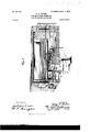
- Figure 1 is a sectional perspective View of a steam-boiler furnace equipped with the present invention.
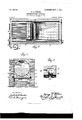
- Fig. 2 isasectional plan view thereof.
- Fig. 3 is a transverse sectional view taken at a point immediately in front of the bafiie-Wall.
- Fig. t is a similar view, on an enlarged scale, of the battle-Wall to disclose more clearly the air-chamber and discharge-nozzles therein.
- the numeral 1 designates a steam-boiler, 2 a series of gratebars arranged in the fire-box 3, and a a bridgewall located in the usual relation to the firebox 3.
- the present invention is designed to introduce a mixture of the character mentioned at such point as will intercept the escaping unconsumed products, so that it will be impossible for the latter to pass to the stack without being acted upon by the mixture and thereby completely consumed.
- bafflewall 5 is provided, said wall being arranged at a point a suitable distance in rear of the bridge-wall 4 and extending transversely of the entire furnace, the bottom of the bafflewall 5 being slightly below the top of the bridge-wall 4, said baffle-wall extending up into contact with the bottom of the boiler 1.
- the object of arranging the baffle-wall 5 in the manner described is to provide a deflector for the products of combustion as they pass over the bridge-wall 4 and to compel said' passage to the stack. Moreover, by providing the baflie-wall 5 at the point indicated is secured the most advantageous point for the introduction of the gaseous mixture, inasmuch as all of the escaping products of combustion must necessarily pass in front of the baffle-wall and thereby be subject to the action of the gaseous mixture when the same is introduced.
- the baffle-wall 5 may be constructed of ordinary brick, or in lieu thereof a special form of fire-brick may be utilized; but this is immaterial.
- the wall 5 is hollow to provide an interior air-space 6, which space communicates with side dues or channels 7, arranged in the side walls of the boiler-setting, and which flues or channels communicate with the atmospheric air, preferably at the rear of the boiler-setting, as clearly shown in Fig. 2. These rear ends may be provided with suitable dampers or other means for controlling the amount of air entering ,the'fiues.
- the front of the baffle-wall 5 is pierced by a multiplicity of discharge-passages 8, which passages are directed toward the bridge-wall I 4, and in order' that the baffle-wall 5 may be effectually supported a circulating-pipe 9 is employed.
- the latter is provided with a series of coils 10, which coils extend across the furnace, and upon said coils the baffle-wall5 is arranged.
- One end of the circulating-pipe 9 communicates with the boiler l at a point near the bottom thereof, said end being provided with a controlling-valve 11, while the other end of the pipe 9 enters the boiler 1 at a point just below the water-line and is likewise provided with a controlling-valve 12, the Valves 11 and 12 being employed in order to control the pressure within the pipe 9.
- baffle-wall 5 purpose in using the circulating-pipe 9 as a support for the baffle-wall 5 is to provide a cooling-surface for said wall in order to prevent too great expansion, which would other wise occur were the baffle-wall supported by nected to a feed-regulator 16.
- the nozzles 13 are so directed as to discharge through the passages 8, and it is obvious that in lieu of arranging the retort 14 at the bottom of the baffle-wall 5 the same might as effectually be applied to the upper portion thereof.
- the retort 14 is connected to a feed-pipe 15, said pipe extending down through the furnace and under the grate-bars 2 and emerging from the front of the boilersetting, at which point said feed-pipe is con- Also connected to the feed-regulator 16 is a conductingpipe 17, which is connected to the upper end of a reservoir 18, the latter being designed to hold-a supply of oil to be fed therefrom by the regulator 16 through the pipe 15 to the .retort 14.
- a pipe 20 may be connected to the steam-pipe 19 and enter may be utilized for the same purpose, which pipe 21 also enters the bottom of the reservoir 18, and'thus the oil within the reservoir is caused to rise upwardly and the feeding of the same from the tank 17 is insured.
- the various pipes are provided with suitable controllingvalves, as indicated, whereby the fluids flowing therethrough may be regulated, and it will also be observed at this point that the invention contemplates an automatically-acting feed-regulator 16, so that the quantity of oil fed thereby into the pipe 15 may be automatically gaged in accordance with the conditions to be met in the fire-box.
- the amount of air within the baffle-wall 5 may be regulated by the dampers at the rear of the channels or fiues 7, so that a proper quantity of air may always be fed to produce the desired gaseous mixture to be discharged from the battle-Wall.
- Through the medium of the pipes 20 and 21 either steam or water pressure may be employed for forcing the oil from the reservoir 18 to the regulator 16, and through said media a uniform pressure on the oil within the tankis insured.
- furnaces of the ordinary construction may be equipped for the prevention of smoke, and the heating capacity of the furnace is greatly increased and at the same time a decrease in the normal fuel consumption is effected.
- baffle arranged in rear of said bridge- Wall and at a point to intercept the products of combustion in their passage to the stack, said baffle being hollow to provide an airspace therein and having an air-inlet, a retort for oil and steam inclosed by one of the walls of the baffle, and means for discharging the oil, steam and air from the baboard and toward the bridge-wall into the path of the escaping products of combustion in their passage to the stack.
- a baffle arranged in rear of said bridgewall and at a point to intercept the products of combustion in their passage to the stack, said baffle being hollow to provide an airspace therein and having an air-inlet, a retort for oil and steam inclosed by one of the walls of the baflie, means for discharging the oil, steam and air from the baffle and toward the bridge-wall into the path of the escaping prodnets of combustion in their passage to the stack, and a circulating-pipe provided with a series of coils, said coils forming a support for the baffle.
- baffle arranged in rear of said bridgewall and at a point to intercept the products of combustion in their passage to the stack, said baffle being hollow to provide an airspace therein and having an air-inlet, said baffle also having a series of discharge-passages directed toward the bridge-wall,a retort for oil and steam inclosed by one of the walls of the baffle, and a series of discharge-nozzles connected with said retort and arranged in said discharge-passages for discharging the oil, steam and air through the latter and toward the bridge-wall into the path of the escaping products of combustion.
- a baffle arranged'i'n rear of said bridgewall and at a point to intercept the products of combustion in their passage to the stack, said baffle being hollow to provide an air-space therein and having an air-inlet, said baffle also having a series of discharge-passages directed toward the bridge-wall, a retort for oil and steam inclosed by one of the walls of the battle, a series of discharge-nozzles connected with said retort and arranged in said discharge-passages for discharging the oil, steam and air through the latter and toward the bridge-wall into the path of the escaping products of combustion,and a circulating-pipe provided with a series of coils, 'said coils forming a support for the baffle.
- a baffle arranged in rear of said bridgewall and at a point to intercept the products of combustion in their passage to the stack, said battle being hollow to provide an air-space therein and having an air-inlet, said baffle also having a series of discharge-passages directed toward the bridge-wall, a retort for oil and steam inclosed by one of the walls of the baffle, a feed-pipe connected to said retort, an oil-reservoir connected to said feed-pipe,
- a steam-pipe also connected to said feed-pipe, whereby the oil and steam combinedare fed to said retort, and a series of discharge-nozzles connected with said retort and arranged in said discharge-passages for discharging the oil, steam and air through the latter and toward the bridge-wall into the path of the escaping products of combustion.
- baffle arranged in rear of said bridgewall and at a point to intercept the products of combustion in their passage to the stack, said baffle being hollow to provide an air-space therein and having an air-inlet,said baffle also having a series of discharge-passages directed toward the bridge-wall, a retort for oil and steam inclosed by one of the walls of the baffle, a feed-pipe connected to said retort, an oil-reservoir connected to said feed-pipe, a steam-pipe also connected to said feed-pipe, whereby the oil and steam combined are fed to said retort, a series of discharge-nozzles connected with said retort and arranged in said discharge-passages for discharging the oil, steam and air through the latter and toward the bridge-Wall into the path of the es- I caping products of combustion, and a circulating-pipe having a coil formed therein to
- baffle arranged in rear of said bridgewall and at a point to intercept the products of combustion in their passage to the stack, said baflle being hollow to provide an airspace therein and having an air-inlet, said baffle also having a series of discharge-passages directed toward the bridge-wall, a retort for oil and steam inclosed by one of the walls of the baffle, a feed-pipe connected to said retort, an oil-reservoir connected to said feed-pipe, a steam-pipe also connected to said feed-pipe, whereby the oil and steam combined are fed to said retort, a series of discharge-nozzles connected with said retort and arranged in said discharge-passages for discharging the oil, steam and air through the latter and toward the bridge-wall into the path of the escaping products of combustion, means for controlling the flow of the oil and steam to the feed-pipe, and a circulating-pipe having a coil formed therein to provide a support for the baffle.
- said bafile being hollowto provide an airspace therein and having an air-inlet
- said baffle also having a series of discharge-passages directed toward the bridge-wall, a retort for oil and steam inclosed by one of the walls of the baffle, a feed-pipe connected to said retort, an oil-reservoir connected to said feed-pipe, a steam-pipe also connected to said feed-pipe, whereby the oil and steam combined are fed to said retort, a series of discharge-nozzles connected with said retort and arranged in said discharge-passages for discharging the oil, steam and air through the latter and toward the bridge-wall into the path of the escaping products of combustion, and a feed-regulator connected to the oil-reservoir and the steam-pipe for controlling the flow of the oil and steam to the feed-pipe.
- a baffle arranged in rear of said bridge- Wall and at a point to intercept the products of combustion in their passage to the stack, said baffle being hollow to provide an airspace therein and having an air-inlet, said baffle also having a series of discharge-passages directed toward the bridge-wall, aretort for oil and steam inclosed by one of the walls of the baffle, a feed-pipe connected to said retort, an oil-reservoir connected to said feed-pipe, a steam-pipe also connected to said feed-pipe, whereby the oil and steam combined are fed to said retort, a series of discharge-nozzles connected with said retort and arranged in said discharge-passages for discharging the oil, steam and air through the latter and toward the bridge-wall into the path of the escaping products of combustion, a feed-regulator connected to the oil-resers voir and the steam-pipe for controlling the flow
Landscapes
- Engineering & Computer Science (AREA)
- Chemical & Material Sciences (AREA)
- Combustion & Propulsion (AREA)
- Mechanical Engineering (AREA)
- General Engineering & Computer Science (AREA)
Description
7 PATENTED SEPT. 1, 1903.
e. A. FISHER. STEAM BOILER FURNACE.
APPLICATION FILED MAR. 30, 1903.
2 SHEETS-SHEET 1.
H0 MODEL.
WITNESSES No. 737,726. PATBNTBD SEPT. 1, 1903. G. A. FISHER. STEAM BOILER FURNACE.
APPLIOATION FILED EAR. 30, 1903. 1 10 IODBL. 2 SHEETS-SHEET 2.
- Attarnej m: Normls PEICRS co. vno'roumu. WASkINGI'ON. nv c.
UNTTED STATES Patented September 1, 19031 PATENT OFFICE.
GEORGE A. FISHER, OF PROVIDENCE, RHODE ISLAND.
STEAM -BO|LER FU RNAC E.
SPECIFICATION forming part of Letters Patent No. 737,726, dated September 1, 1903.
Application filed March 30, 1903. Serial No. 150,239. (No model.)
To all whom, it may concern:
Be it known that I, GEORGE A. FISHER, a citizen of the United States, residing at Providence, in the county of Providence and State of Rhode Island, have invented certain new and useful Improvements in Steam-Boiler Furnaces; and I do hereby declare the following to be a full, clear, and exact description of the invention, such as will enable others skilled in the art to which it appertains to make and use the same.
This invention relates to improvements in steam-boiler furnaces, and more particularly relates to furnaces of the smoke-consuming type.
The object of the present invention is the provision of simple and efficient means designed to be used in conjunction with furnaces ordinarily employed, but without the necessity of altering their construction, whereby the products of combustion are entirely consumed, thereby greatly increasing the heating capacity of the furnace and at the same time effecting a decrease in the normal consumption of fuel.
A further object of the present invention is the provision of simple and eflicient means adapted to effect complete combustion of the unconsumed particles by the use of a gaseous mixture employed as an auxiliary to the solid fuel and introduced at such points within the furnace as to intercept the unconsumed particles and insure their absolute consumption before the same are permitted to enter the stack.
A further object contemplated by the present invention is to provide means for introducing a combined mixture of steam, oil, and air at a point for action upon the unconsu med particles which will prove the most advantageous for the complete combustion of the unconsumed particles. It is recognized that in the prior art a mixture of the character mentioned has been previously employed in attempts to render steam-boiler furnaces smokeless; but in the constructions adopted for the use of the gaseous mixture the latter has been introduced only by complicated devices and methods. The present invention aims to provide a simplified construction of apparatus for utilizing the gaseous mixture, and one which may be installed at a minimum cost and which will require no material expense for its maintenance.
With these general objects in View and others which Will appear as the nature of the improvements is better understood the invention consists, substantially, in the novel construction, combination, and arrangement of parts, as will be hereinafter fully described, illustrated in the accompanying drawings, and pointed out in the appended claims.
While the form of the invention herein shown and described is What is believed to be a preferable embodiment thereof, it will be understood that the same is susceptible of various changes in the form, proportion, and minor details of construction, and the right is accordingly hereby reserved to modify or vary the invention as falls within the spirit and scope thereof.
In the drawings, Figure 1 is a sectional perspective View of a steam-boiler furnace equipped with the present invention. Fig. 2 isasectional plan view thereof. Fig. 3 is a transverse sectional view taken at a point immediately in front of the bafiie-Wall. Fig. tis a similar view, on an enlarged scale, of the battle-Wall to disclose more clearly the air-chamber and discharge-nozzles therein.
Referring to the drawings, the numeral 1 designates a steam-boiler, 2 a series of gratebars arranged in the fire-box 3, and a a bridgewall located in the usual relation to the firebox 3. These parts are all of the ordinary construction, and therefore require no detailed description.
In the ordinary construction of steam-boiler bustion rise from the fire-box and pass over the bridge-wall 4, whence the same pass beneath the boiler, through the fines thereof, and out into the stack. Various attempts have been made with a View to consuming the escaping products of combustion in order to render the boiler-furnaces smokeless, and to this end it is recognized that in the prior art a combined mixture of steam, oil, and air has been introduced into boiler-furnaces for action upon the products of combustion in attempts to completely consume the same. The introduction, however, of this combined complished by the use of complicated devices furnaces the unconsumed products of commixture in many instances has been only ac and methods, and the combined mixture has also been introduced at such points as would preclude a complete consumption of the unconsumed particles. As before premised, the present invention is designed to introduce a mixture of the character mentioned at such point as will intercept the escaping unconsumed products, so that it will be impossible for the latter to pass to the stack without being acted upon by the mixture and thereby completely consumed. To this end a bafflewall 5 is provided, said wall being arranged at a point a suitable distance in rear of the bridge-wall 4 and extending transversely of the entire furnace, the bottom of the bafflewall 5 being slightly below the top of the bridge-wall 4, said baffle-wall extending up into contact with the bottom of the boiler 1.
The object of arranging the baffle-wall 5 in the manner described is to provide a deflector for the products of combustion as they pass over the bridge-wall 4 and to compel said' passage to the stack. Moreover, by providing the baflie-wall 5 at the point indicated is secured the most advantageous point for the introduction of the gaseous mixture, inasmuch as all of the escaping products of combustion must necessarily pass in front of the baffle-wall and thereby be subject to the action of the gaseous mixture when the same is introduced. The baffle-wall 5 may be constructed of ordinary brick, or in lieu thereof a special form of fire-brick may be utilized; but this is immaterial. The wall 5 is hollow to provide an interior air-space 6, which space communicates with side dues or channels 7, arranged in the side walls of the boiler-setting, and which flues or channels communicate with the atmospheric air, preferably at the rear of the boiler-setting, as clearly shown in Fig. 2. These rear ends may be provided with suitable dampers or other means for controlling the amount of air entering ,the'fiues. The front of the baffle-wall 5 is pierced by a multiplicity of discharge-passages 8, which passages are directed toward the bridge-wall I 4, and in order' that the baffle-wall 5 may be effectually supported a circulating-pipe 9 is employed. The latter is provided with a series of coils 10, which coils extend across the furnace, and upon said coils the baffle-wall5 is arranged. One end of the circulating-pipe 9 communicates with the boiler l at a point near the bottom thereof, said end being provided with a controlling-valve 11, while the other end of the pipe 9 enters the boiler 1 at a point just below the water-line and is likewise provided with a controlling-valve 12, the Valves 11 and 12 being employed in order to control the pressure within the pipe 9. The
purpose in using the circulating-pipe 9 as a support for the baffle-wall 5 is to provide a cooling-surface for said wall in order to prevent too great expansion, which would other wise occur were the baffle-wall supported by nected to a feed-regulator 16.
erably arranged in the bottom of the baiflewall 5. The nozzles 13 are so directed as to discharge through the passages 8, and it is obvious that in lieu of arranging the retort 14 at the bottom of the baffle-wall 5 the same might as effectually be applied to the upper portion thereof. The retort 14 is connected to a feed-pipe 15, said pipe extending down through the furnace and under the grate-bars 2 and emerging from the front of the boilersetting, at which point said feed-pipe is con- Also connected to the feed-regulator 16 is a conductingpipe 17, which is connected to the upper end of a reservoir 18, the latter being designed to hold-a supply of oil to be fed therefrom by the regulator 16 through the pipe 15 to the .retort 14. However, in order to accomplish such feeding a steam-pipe 19, connected to the boiler at a suitable point, is also connected to the regulator 16, and thus the steam acting as a motive force causes the quantity of oil fed by the regulator 16 to pass through the pipe 15 to the retort 14. It will thus be seen that the steam and oil combined are fed to the retort 14, and passing through the latter the mixture of steam and oil becomes superheated, so that when the sameemerges from the discharge-nozzles 13 such mixture will combine with the air within the baffle-wall, and the combined mixture of steam, oil, and air is thus discharged through the passages 8 directly in front of the baffle-wall 5 toward the bridge-wall 4 and into the escaping products of combustion as the same pass over the bridge-wall 4.
To effect a proper flow ofthe oil from the reservoir 18 to the regulator 16, a pipe 20 may be connected to the steam-pipe 19 and enter may be utilized for the same purpose, which pipe 21 also enters the bottom of the reservoir 18, and'thus the oil within the reservoir is caused to rise upwardly and the feeding of the same from the tank 17 is insured. It will of course be understood that the various pipes are provided with suitable controllingvalves, as indicated, whereby the fluids flowing therethrough may be regulated, and it will also be observed at this point that the invention contemplates an automatically-acting feed-regulator 16, so that the quantity of oil fed thereby into the pipe 15 may be automatically gaged in accordance with the conditions to be met in the fire-box.
From the foregoing description the operation of the herein-described apparatus will be apparent, but, briefly stated, is as follows: The oil passing from the reservoir 18-is fed in predetermined quantities through the regulator 16 into the pipe 15, combined with the steam from the pipe 19, and the steam thereby forces the oil to the retort 14., where superheating takes place, and in discharging through the nozzles 13 the combined steam and oil again mixed with the air within the baffle-wall 5, which admixture discharges through the passages 8 directly in front of the baffle-wall. The unconsumed particles of the escaping products of combustion passing over the bridge-wall 4 are directly intercepted by the gaseous mixture so produced, and by said products said mixture becomes ignited with a resultant combustion of the unconsnmed particles by the ignited mixture. Consequently there remain no unconsumed particles; but a very intense heatis produced, and this heat passing through the boiler is discharged into the stack in the usual manner. By discharging the gaseous mixture toward the bridge-wall such mixture is forced in a positive manner against the escaping products of combustion and the draft in contradistinction to flowing in the same direction taken by the draft and the products of combustion, and the latter are thereby retarded by the gaseous mixture, thus insuring a complete consumption of the escaping products by said mixture. The amount of air within the baffle-wall 5 may be regulated by the dampers at the rear of the channels or fiues 7, so that a proper quantity of air may always be fed to produce the desired gaseous mixture to be discharged from the baiile-Wall. Water from the boiler 1, circulating through the pipe 9 and the coils 10 thereof, acts to cool the baffle-wall 5 and prevent excessive expansion thereof, and the water in said pipe is in turn highly heated by the intense heat produced at the baffle-wall, so that the same is returned to the boiler in a more highly heated state than when withdrawn therefrom. Through the medium of the pipes 20 and 21 either steam or water pressure may be employed for forcing the oil from the reservoir 18 to the regulator 16, and through said media a uniform pressure on the oil within the tankis insured.
By the use of the present invention furnaces of the ordinary construction may be equipped for the prevention of smoke, and the heating capacity of the furnace is greatly increased and at the same time a decrease in the normal fuel consumption is effected.
Having thus describedthe invention, what is claimed as new, and desired to be secured by Letters Patent, is
1. In a steam-boiler furnace, the combination with the fire-box and bridge-wall thereof, of a baffle arranged in rear of said bridge- Wall and at a point to intercept the products of combustion in their passage to the stack, said baffle being hollow to provide an airspace therein and having an air-inlet, a retort for oil and steam inclosed by one of the walls of the baffle, and means for discharging the oil, steam and air from the baiile and toward the bridge-wall into the path of the escaping products of combustion in their passage to the stack.
2. In a steam-boiler furnace, the combination with the fire-box and bridge-wall thereof, of a baffle arranged in rear of said bridgewall and at a point to intercept the products of combustion in their passage to the stack, said baffle being hollow to provide an airspace therein and having an air-inlet, a retort for oil and steam inclosed by one of the walls of the baflie, means for discharging the oil, steam and air from the baffle and toward the bridge-wall into the path of the escaping prodnets of combustion in their passage to the stack, and a circulating-pipe provided with a series of coils, said coils forming a support for the baffle.
3. In a steam-boiler furnace, the combination with the fire-box and bridge-wall thereof, of a baffle arranged in rear of said bridgewall and at a point to intercept the products of combustion in their passage to the stack, said baffle being hollow to provide an airspace therein and having an air-inlet, said baffle also having a series of discharge-passages directed toward the bridge-wall,a retort for oil and steam inclosed by one of the walls of the baffle, and a series of discharge-nozzles connected with said retort and arranged in said discharge-passages for discharging the oil, steam and air through the latter and toward the bridge-wall into the path of the escaping products of combustion.
4. In a steam-boiler furnace, the combination with the tire-box and bridge-wall thereof, of a baffle arranged'i'n rear of said bridgewall and at a point to intercept the products of combustion in their passage to the stack, said baffle being hollow to provide an air-space therein and having an air-inlet, said baffle also having a series of discharge-passages directed toward the bridge-wall, a retort for oil and steam inclosed by one of the walls of the battle, a series of discharge-nozzles connected with said retort and arranged in said discharge-passages for discharging the oil, steam and air through the latter and toward the bridge-wall into the path of the escaping products of combustion,and a circulating-pipe provided with a series of coils, 'said coils forming a support for the baffle.
5. In a steam-boiler furnace, the combination with the fire-box and bridge-wall thereof, of a baffle arranged in rear of said bridgewall and at a point to intercept the products of combustion in their passage to the stack, said battle being hollow to provide an air-space therein and having an air-inlet, said baffle also having a series of discharge-passages directed toward the bridge-wall, a retort for oil and steam inclosed by one of the walls of the baffle, a feed-pipe connected to said retort, an oil-reservoir connected to said feed-pipe,
IIO
a steam-pipe also connected to said feed-pipe, whereby the oil and steam combinedare fed to said retort, and a series of discharge-nozzles connected with said retort and arranged in said discharge-passages for discharging the oil, steam and air through the latter and toward the bridge-wall into the path of the escaping products of combustion.
6. In a steam-boiler furnace, the combination with the fire-box and bridge-wall thereof, of a baffle arranged in rear of said bridgewall and at a point to intercept the products of combustion in their passage to the stack, said baffle being hollow to provide an air-space therein and having an air-inlet,said baffle also having a series of discharge-passages directed toward the bridge-wall, a retort for oil and steam inclosed by one of the walls of the baffle, a feed-pipe connected to said retort, an oil-reservoir connected to said feed-pipe, a steam-pipe also connected to said feed-pipe, whereby the oil and steam combined are fed to said retort, a series of discharge-nozzles connected with said retort and arranged in said discharge-passages for discharging the oil, steam and air through the latter and toward the bridge-Wall into the path of the es- I caping products of combustion, and a circulating-pipe having a coil formed therein to provide a support for the baffle.
7. In a steam-boiler furnace, the combination with the fire-box and bridge-wall thereof,
of a baffle arranged in rear of said bridgewall and at a point to intercept the products of combustion in their passage to the stack, said baflle being hollow to provide an airspace therein and having an air-inlet, said baffle also having a series of discharge-passages directed toward the bridge-wall, a retort for oil and steam inclosed by one of the walls of the baffle, a feed-pipe connected to said retort, an oil-reservoir connected to said feed-pipe, a steam-pipe also connected to said feed-pipe, whereby the oil and steam combined are fed to said retort, a series of discharge-nozzles connected with said retort and arranged in said discharge-passages for discharging the oil, steam and air through the latter and toward the bridge-wall into the path of the escaping products of combustion, means for controlling the flow of the oil and steam to the feed-pipe, and a circulating-pipe having a coil formed therein to provide a support for the baffle.
remiss wall and at a point to intercept the products of combustion in their passage to the stack, said bafile being hollowto provide an airspace therein and having an air-inlet, said baffle also having a series of discharge-passages directed toward the bridge-wall, a retort for oil and steam inclosed by one of the walls of the baffle, a feed-pipe connected to said retort, an oil-reservoir connected to said feed-pipe, a steam-pipe also connected to said feed-pipe, whereby the oil and steam combined are fed to said retort, a series of discharge-nozzles connected with said retort and arranged in said discharge-passages for discharging the oil, steam and air through the latter and toward the bridge-wall into the path of the escaping products of combustion, and a feed-regulator connected to the oil-reservoir and the steam-pipe for controlling the flow of the oil and steam to the feed-pipe.
9. In a steam-boiler furnace, the combination with the fire-box and bridge-wall thereof, of a baffle arranged in rear of said bridge- Wall and at a point to intercept the products of combustion in their passage to the stack, said baffle being hollow to provide an airspace therein and having an air-inlet, said baffle also having a series of discharge-passages directed toward the bridge-wall, aretort for oil and steam inclosed by one of the walls of the baffle, a feed-pipe connected to said retort, an oil-reservoir connected to said feed-pipe, a steam-pipe also connected to said feed-pipe, whereby the oil and steam combined are fed to said retort, a series of discharge-nozzles connected with said retort and arranged in said discharge-passages for discharging the oil, steam and air through the latter and toward the bridge-wall into the path of the escaping products of combustion, a feed-regulator connected to the oil-resers voir and the steam-pipe for controlling the flow of the oil and steam to the feed-pipe, and a circulating-pipe having a coil formed therein to provide a support for the baffle.
In testimony whereof I affix my signature in the presence of two witnesses.
' GEORGE A. FISHER.
Witnesses:
H. H. SHERMAN,
C. A. PHILLIPS.
Priority Applications (1)
| Application Number | Priority Date | Filing Date | Title |
|---|---|---|---|
| US15023903A US737726A (en) | 1903-03-30 | 1903-03-30 | Steam-boiler furnace. |
Applications Claiming Priority (1)
| Application Number | Priority Date | Filing Date | Title |
|---|---|---|---|
| US15023903A US737726A (en) | 1903-03-30 | 1903-03-30 | Steam-boiler furnace. |
Publications (1)
| Publication Number | Publication Date |
|---|---|
| US737726A true US737726A (en) | 1903-09-01 |
Family
ID=2806233
Family Applications (1)
| Application Number | Title | Priority Date | Filing Date |
|---|---|---|---|
| US15023903A Expired - Lifetime US737726A (en) | 1903-03-30 | 1903-03-30 | Steam-boiler furnace. |
Country Status (1)
| Country | Link |
|---|---|
| US (1) | US737726A (en) |
-
1903
- 1903-03-30 US US15023903A patent/US737726A/en not_active Expired - Lifetime
Similar Documents
| Publication | Publication Date | Title |
|---|---|---|
| US737726A (en) | Steam-boiler furnace. | |
| US719613A (en) | Heating-furnace. | |
| US711044A (en) | Locomotive-boiler. | |
| US234972A (en) | William ennis | |
| US795894A (en) | Steam-boiler furnace. | |
| US707996A (en) | Steam-generator. | |
| US626657A (en) | Hollow grate-bar | |
| US1052796A (en) | Method of producing a substantially complete combustion of fuel. | |
| US652110A (en) | Furnace. | |
| US170198A (en) | Improvement in hydrocarbon-furnaces | |
| US358351A (en) | Boiler-furnace | |
| US798248A (en) | Steam-boiler furnace. | |
| US738132A (en) | Furnace. | |
| US252213A (en) | harris | |
| US759061A (en) | Smoke-consumer and fuel-economizer. | |
| US736066A (en) | Air-feeding apparatus for locomotives. | |
| US668463A (en) | Steam-generator and furnace therefor. | |
| US177467A (en) | Improvement in furnaces and boiler-settings | |
| US303963A (en) | Furnace | |
| US212366A (en) | Improvement in furnaces | |
| US723860A (en) | Steam-boiler setting. | |
| US252214A (en) | haeeis | |
| US842189A (en) | Smoke-consuming furnace. | |
| US179837A (en) | Improvement in steam-boiler furnaces | |
| US764304A (en) | Smoke-consuming apparatus for locomotive-boilers. |