US7351848B2 - Method and apparatus for preparing a dialkyl carbonate, and its use in the preparation of diaryl carbonates and polycarbonates - Google Patents
Method and apparatus for preparing a dialkyl carbonate, and its use in the preparation of diaryl carbonates and polycarbonates Download PDFInfo
- Publication number
- US7351848B2 US7351848B2 US10/227,111 US22711102A US7351848B2 US 7351848 B2 US7351848 B2 US 7351848B2 US 22711102 A US22711102 A US 22711102A US 7351848 B2 US7351848 B2 US 7351848B2
- Authority
- US
- United States
- Prior art keywords
- fluid passageway
- hydrochloric acid
- liquid fraction
- concentration
- carbon monoxide
- Prior art date
- Legal status (The legal status is an assumption and is not a legal conclusion. Google has not performed a legal analysis and makes no representation as to the accuracy of the status listed.)
- Expired - Fee Related, expires
Links
- 0 *OC(=O)O*.O=C(O)O.[Ar].[Ar].[Ar].[Ar].[O-][O-] Chemical compound *OC(=O)O*.O=C(O)O.[Ar].[Ar].[Ar].[Ar].[O-][O-] 0.000 description 5
- URUPYCMUWQJNND-UHFFFAOYSA-N C.CC(C)=O.O.[C-]#[O+] Chemical compound C.CC(C)=O.O.[C-]#[O+] URUPYCMUWQJNND-UHFFFAOYSA-N 0.000 description 1
- HBHJVVHITORQPI-UHFFFAOYSA-N C.CCO.CCOC(=O)OC.O=C(O)O.[Ar].[Ar] Chemical compound C.CCO.CCOC(=O)OC.O=C(O)O.[Ar].[Ar] HBHJVVHITORQPI-UHFFFAOYSA-N 0.000 description 1
Images


Classifications
-
- C—CHEMISTRY; METALLURGY
- C07—ORGANIC CHEMISTRY
- C07C—ACYCLIC OR CARBOCYCLIC COMPOUNDS
- C07C68/00—Preparation of esters of carbonic or haloformic acids
-
- B—PERFORMING OPERATIONS; TRANSPORTING
- B01—PHYSICAL OR CHEMICAL PROCESSES OR APPARATUS IN GENERAL
- B01J—CHEMICAL OR PHYSICAL PROCESSES, e.g. CATALYSIS OR COLLOID CHEMISTRY; THEIR RELEVANT APPARATUS
- B01J19/00—Chemical, physical or physico-chemical processes in general; Their relevant apparatus
- B01J19/0006—Controlling or regulating processes
- B01J19/002—Avoiding undesirable reactions or side-effects, e.g. avoiding explosions, or improving the yield by suppressing side-reactions
-
- C—CHEMISTRY; METALLURGY
- C07—ORGANIC CHEMISTRY
- C07C—ACYCLIC OR CARBOCYCLIC COMPOUNDS
- C07C68/00—Preparation of esters of carbonic or haloformic acids
- C07C68/01—Preparation of esters of carbonic or haloformic acids from carbon monoxide and oxygen
-
- B—PERFORMING OPERATIONS; TRANSPORTING
- B01—PHYSICAL OR CHEMICAL PROCESSES OR APPARATUS IN GENERAL
- B01J—CHEMICAL OR PHYSICAL PROCESSES, e.g. CATALYSIS OR COLLOID CHEMISTRY; THEIR RELEVANT APPARATUS
- B01J2219/00—Chemical, physical or physico-chemical processes in general; Their relevant apparatus
- B01J2219/00002—Chemical plants
- B01J2219/00004—Scale aspects
- B01J2219/00006—Large-scale industrial plants
-
- B—PERFORMING OPERATIONS; TRANSPORTING
- B01—PHYSICAL OR CHEMICAL PROCESSES OR APPARATUS IN GENERAL
- B01J—CHEMICAL OR PHYSICAL PROCESSES, e.g. CATALYSIS OR COLLOID CHEMISTRY; THEIR RELEVANT APPARATUS
- B01J2219/00—Chemical, physical or physico-chemical processes in general; Their relevant apparatus
- B01J2219/00049—Controlling or regulating processes
- B01J2219/00245—Avoiding undesirable reactions or side-effects
- B01J2219/00247—Fouling of the reactor or the process equipment
-
- B—PERFORMING OPERATIONS; TRANSPORTING
- B01—PHYSICAL OR CHEMICAL PROCESSES OR APPARATUS IN GENERAL
- B01J—CHEMICAL OR PHYSICAL PROCESSES, e.g. CATALYSIS OR COLLOID CHEMISTRY; THEIR RELEVANT APPARATUS
- B01J2219/00—Chemical, physical or physico-chemical processes in general; Their relevant apparatus
- B01J2219/00049—Controlling or regulating processes
- B01J2219/00245—Avoiding undesirable reactions or side-effects
- B01J2219/00272—Addition of reaction inhibitor
Definitions
- Polycarbonate resins are useful materials valued for their physical and optical properties.
- Methods for the preparation of polycarbonate resins include interfacial processes and melt processes.
- interfacial processes as described, for example, in U.S. Pat. No. 4,360,659 to Sikdar, a bisphenol is reacted with phosgene in the presence of solvents.
- melt processes as described, for example, in U.S. Pat. No. 3,153,008 to Fox, a bisphenol is reacted with a diaryl carbonate. Melt processes are presently preferred because they avoid the use of phosgene and solvents.
- diaryl carbonates are produced by reacting dialkyl carbonates with aryl hydroxides (see Scheme I, below).
- a typical plant for performing preparing dialkyl carbonates according to Scheme III may contain three sections: a reaction section for converting raw materials to dialkyl carbonate, a separation section for isolating the dialkyl carbonate from unreacted monomers and by-products, and a purification section for removing water and further isolating the dialkyl carbonate.
- the '943 Patent teaches that one can minimize the amount of corrosion-resistant equipment required by removing the HCl from the process stream immediately after the reaction section. This eliminates the necessity of using expensive corrosion-resistant materials in the separation and purification sections of the plant.
- the '943 Patent further suggests that removal of HCl and possible copper halide salts from the stream immediately after the reaction section can be accomplished by exposing the gas-liquid mixture produced by the reaction to a liquid stream consisting of one of the process fluids.
- the '943 Patent also states that the operating conditions employed are preferably adjusted such that the gaseous mixture from the reactor does not condense, or condenses only to a negligible extent, before the acid removal section in order to avoid the necessity of having to reheat the mixture before removing the HCl (col. 3, lines 17-30).
- a method of preparing a dialkyl carbonate comprising: reacting an alkanol, oxygen, carbon monoxide, and a catalyst to form a mixture comprising a dialkyl carbonate, an alkyl chloroformate, hydrochloric acid, water, carbon dioxide, and carbon monoxide; separating from the reaction mixture a liquid fraction comprising alkyl chloroformate; and passing said liquid fraction through a fluid passageway at a temperature of about 30° C. to about 130° C. and for a time of about 0.5 hour to about 10 hours; wherein said fluid passageway has a length to diameter ratio of at least about 0.2.
- methyl chloroformate (hereinafter “MCF”) may be formed as a by-product.
- DMC dimethyl carbonate
- MCF methyl chloroformate
- the MCF may pass through the HCl removal column into the separator and purification sections, where it reacts slowly with methanol and/or water to form corrosive HCl. Therefore, it was determined that steps were needed to remove MCF prior to the separation and purification sections.
- FIG. 1 is a diagrammatic view of a first embodiment of the apparatus.
- FIG. 2 is a simplified diagrammatic view of a comparative apparatus that is susceptible to corrosion.
- FIG. 3 is a simplified diagrammatic view of an embodiment of the apparatus in which the fluid passageway 110 comprises two holding vessels 120 .
- FIG. 4 is a simplified diagrammatic view of an embodiment of the apparatus in which the fluid passageway 110 comprises four holding vessels 120 .
- FIG. 5 is a simplified diagrammatic view of an embodiment of the apparatus in which the fluid passageway 110 comprises a tubular section 130 .
- FIG. 6 is a simplified diagrammatic view of an embodiment of the apparatus comprising an ion exchange resin bed 190 .
- FIG. 7 is a simplified diagrammatic view of an embodiment of the apparatus in which the fluid passageway 110 comprises a first gas-liquid separator 90 and a second gas-liquid separator 100 .
- FIG. 8 is a simplified diagrammatic view of an embodiment of the apparatus in which the fluid passageway 110 precedes the first gas-liquid separator 90 .
- FIG. 9 is a simplified diagrammatic view of an embodiment of the apparatus in which the fluid passageway 110 follows the azeotrope column 180 .
- FIG. 10 is a plot of chloride concentrations at the bottom of an azeotrope column 180 as a function of apparatus type ( FIG. 2 and FIG. 3 ) and time.
- FIG. 11 is a plot of methyl chloroformate concentrations entering and exiting the fluid passageway 110 as a function of time for an apparatus corresponding to FIG. 3 .
- One embodiment is a method, comprising: reacting an alkanol, oxygen, carbon monoxide, and a catalyst to form a mixture comprising a dialkyl carbonate, an alkyl chloroformate, hydrochloric acid, water, carbon dioxide, and carbon monoxide; and removing alkyl chloroformate from said mixture.
- alkanol used in the method.
- Suitable alkanols include primary, secondary, and tertiary C 1 -C 12 alkanols, with primary C 1 -C 6 alkanols being preferred.
- Highly preferred alkanols include methanol.
- Oxygen may be provided in any form, with gaseous forms being preferred.
- Suitable oxygen sources include, for example, air, and oxygen-containing gases having at least about 95 weight percent molecular oxygen, preferably at least about 99 weight percent molecular oxygen.
- Suitable oxygen-containing gases are commercially available from, for example, Air Products.
- Carbon monoxide is preferably supplied as a gas having at least about 90 weight percent, preferably at least about 95 weight percent, more preferably at least about 99 weight percent, carbon monoxide.
- Suitable carbon monoxide-containing gases are commercially available from, for example, Air Products.
- Suitable catalyst include those comprising iron, copper, nickel, cobalt, zinc, ruthenium, rhodium, palladium, silver, cadmium, rhenium, osmium, iridium, platinum, gold, mercury, and the like, and combinations comprising at least one of the foregoing metals.
- Preferred catalysts may comprise copper.
- a highly preferred catalyst comprises copper and chloride ion in a molar ratio of about 0.5 to about 1.5. Within this range, a molar ratio of at least about 0.8 may be preferred. Also within this range, a molar ratio of up to about 1.2 may be preferred.
- Highly preferred catalysts include cuprous chloride (CuCl) and cupric chloride (CuCl 2 ), with cuprous chloride being more highly preferred.
- a suitable chloride ion concentration may be maintained by the addition of hydrochloric acid (HCl).
- FIG. 1 illustrates a dialkyl carbonate plant 10 having linked reaction section 20 , separation section 30 , and purification section 40 .
- the catalyzed reaction of alkanol, oxygen, and carbon monoxide may be performed in a single reactor 50 , or in two or more reactors 50 .
- the conditions for performing this step should be selected to maximize the yield of dialkyl carbonate while minimizing the degradation of dialkyl carbonate.
- the reaction is performed in a single reactor 50 , at a temperature of about 50° C. to about 250° C. Within this range, the temperature may preferably be at least about 100° C. Also within this range, the temperature may preferably be up to about 150° C.
- the reactor 50 is preferably kept at a pressure of about 15 to about 35 bar gauge (barg). Within this range, a pressure of at least about 20 barg may be preferred. Also within this range, a pressure up to about 28 barg may be preferred. In the case of dual reactor systems, the catalyst may be recycled between tanks.
- the catalyst concentration should be sufficiently high to produce an acceptable yield, but should be kept below a concentration that would cause solid setting of the catalyst in the reactor 50 or clogging of the equipment.
- the reactants alkanol, oxygen, and carbon monoxide are preferably added to the reactor in a molar ratio of (about 0.5 to about 0.7):(about 0.04 to about 0.06):(about 0.8 to about 1.2), respectively.
- a highly preferred molar ratio of alkanol:oxygen:carbon monoxide is (about 0.6):(about 0.05):(about 1).
- the amount of catalyst used relative to the reactants will depend on the identity of the catalyst. For example, when the catalyst comprises CuCl, a highly preferred catalyst concentration is about 140 to about 180 grams per liter of reaction mixture.
- the catalyst may initially be added from a catalyst tank 60 .
- Sufficient HCl is preferably added to reactor 50 from a hydrochloric acid tank 70 during the course of the reaction to maintain a molar ratio of Cu:Cl close to 1.0.
- the concentration of HCl is preferably continuously determined and controlled by the addition of HCl.
- a typical mass ratio for HCl feed to total liquid feed is about 6 ⁇ 10 ⁇ 4 to about 8 ⁇ 10 ⁇ 4 .
- the reaction produces a mixture comprising a dialkyl carbonate, an alkyl chloroformate, hydrochloric acid, water, carbon dioxide, and carbon monoxide.
- the mixture may further comprise residual methanol and oxygen, as well as side-products such as alkyl chlorides and dialkyl ethers.
- the mixture is typically withdrawn from the reactor 50 in a gas/vapor form.
- vapor is meant to refer to gaseous organic components of the mixture such as, for example, evaporated dialkyl carbonates, alcohols, alkyl chlorofornates, etc., and to water vapor. That is, the term “vapor” refers to fluids having a boiling point of at least ⁇ 50° C. at one atmosphere.
- gas is meant to refer to the gaseous oxygen, carbon dioxide, carbon monoxide, and optional nitrogen. That is, the term “gas” refers to fluids having a boiling point less than ⁇ 50° C. at one atmosphere.
- the vapor may be at least partially condensed in condenser 80 , and fed to a first gas-liquid separator 90 .
- the apparatus may optionally employ a single gas-liquid separator, or a plurality of (i.e., at least 2; preferably up to about 5) gas-liquid separators.
- the first gas-liquid separator 90 may be kept at a pressure within about 10%, more preferably within about 1%, of the pressure of the reactor 50 .
- the gas effluent from the first gas-liquid separator 90 may be recycled, for example to reuse excess carbon monoxide.
- the mixture may be sent to a second gas-liquid separator 100 , which preferably has a pressure less than about 20% of the pressure of the reactor 50 (e.g., preferably less than 3 bar gauge, more preferably about 0.2 bar gauge) to preferably achieve separation of at least about 90%, more preferably at least 95%, by weight of the remaining gas in the mixture.
- substantially all of the gas is removed from the mixture.
- the gas effluent removed from the second gas-liquid separator 100 can also be recycled.
- the vapor in the mixture be in a partially condensed form (i.e., at least about 10% condensed), more preferably a fully condensed form (i.e., at least about 90% condensed), before entering the first gas-liquid separator 90 , and between the first gas-liquid separator 90 and the second gas-liquid separator 100 .
- the mixture exiting the second gas-liquid separator 100 may be in a single liquid phase (liquid fraction).
- the liquid fraction may proceed through a fluid passageway 110 that removes alkyl chloroform ate from the mixture.
- a fluid passageway 110 that removes alkyl chloroform ate from the mixture.
- Some preferred methods include heating, increasing pressure, increasing residence time, adding a polar solvent, adsorbing, separating with a membrane (including gas and liquid membrane separation), pervaporating, passing through an ion exchange resin, exposing to a stoichiometric reagent, exposing to a catalytic reagent, and the like, and combinations comprising at least one of the foregoing techniques.
- the alkyl chloroforinate is removed from mixture by reaction with water (see Scheme IV) or alkanol (see Scheme V).
- alkyl chloroformate without passing the liquid fraction through an ion exchange resin, because such resins are expensive to install and operate. It may be preferred to remove at least about 50 percent, more preferably at least about 90 percent, yet more preferably at least about 95 percent, even more preferably at least about 99 percent, of the alkyl chloroformate from the liquid fraction. In one embodiment, it may be preferred to reduce the alkyl chloroformate concentration in the liquid fraction to less than about 500 ppm, more preferably less than about 100 ppm, yet more preferably less than about 30 ppm.
- dialkyl carbonate it may be preferred to remove less than about 10%, more preferably less than about 5%, yet more preferably less than about 1%, of the dialkyl carbonate.
- the method may be described as “removing less than about 10% of said dialkyl carbonate”, it will be understood that the concentration of dialkyl carbonate need not be reduced and may even increase.
- the concentration of dialkyl carbonate may increase if the Scheme V reaction of alkyl chloroformate with methanol forms dialkyl carbonate faster than dialkyl carbonate decomposes due to other reactions.
- ⁇ r MCF ( k 1 [H 2 O]+ k 2 [MeOH])[MCF] (1)
- r MCF is the rate of change of the moles of methyl chloroformate (MCF) per unit volume
- [H 2 O]] [MeOH]
- [MCF] are the instantaneous concentrations of water, methanol, and methyl chloroforrnate, respectively, in moles per unit volume
- k 2 k 2 0 e ⁇ 7673/T (3)
- k 1 0 2.09 ⁇ 10 9 mL/mol-min
- k 2 rate constants that vary with temperature according to equations (2) and (3)
- the value of X may preferably be less than about 0.5, more preferably less than about 0.2, yet more preferably be less than about 0.1, even more preferably less than about 0.05, still more preferably less than about 0.01.
- the water concentration may be about 0.1 to about 50 moles per liter (mol/L). Within this range, the water concentration may preferably be at least about 0.5 mol/L, more preferably at least about 1 mol/L. Also within this range, the water concentration may preferably be up to about 30 mol/L, more preferably up to about 20 mol/L, yet more preferably up to about 10 mol/L, even more preferably up to about 5 mol/L.
- the methanol concentration may be about 1 to about 25 mol/L.
- the methanol concentration may preferably be at least about 5 mol/L, more preferably at least about 10 mol/L. Also within this range, the methanol concentration may preferably be up to about 20 mol/L, more preferably up to about 18 mol/L.
- the time may be about 0.5 hour to about 10 hours. Within this range, the time may preferably be at least about 1 hours, more preferably at least about 2 hours. Also within this range, the time may preferably be up to about 8 hours, more preferably up to about 6 hours.
- the temperature may be about 30 to about 130° C. Within this range, the temperature may preferably be at least about 40° C., more preferably at least about 50° C., yet more preferably at least about 60° C. Also within this range, the temperature may preferably be up to about 110° C., more preferably up to about 100° C., yet more preferably up to about 90° C.
- the rate of methyl chloroformate decomposition may be expressed according to equation (4), with t representing time in minutes.
- the concentration of methyl chloroformate at residence time t R is given by equation (6)
- t R is the residence time in minutes
- k is given by equation (7)
- k k 1 [H 2 O]+ k 2 [MeOH] (7)
- k 1 , k 2 , [H 2 O], and [MeOH] are as defined above.
- the residence time t R may be defined as the average time spent by a molecule in the fluid passageway 110 .
- the temperature, time, methanol concentration, and water concentration in this expression are as described above.
- the initial concentration of methyl chloroformate will depend on the reactor conditions, but it is typically about 5 ⁇ 10 ⁇ 3 moles per liter to about 5 ⁇ 10 ⁇ 1 moles per liter. Within this range, the initial concentration of methyl chloroformate may be at least about 1 ⁇ 10 ⁇ 2 moles per liter. Also within this range, the initial concentration of methyl chloroformate may be up to about 1 ⁇ 10 ⁇ 1 moles per liter.
- the value of Y may preferably be at least about 0.95, more preferably at least about 0.99.
- Suitable analytical techniques to determine initial concentrations of water, methanol, hydrochloric acid, and dimethyl carbonate in reaction mixtures are well known in the art.
- the term “initial concentration” refers to the concentration of a species before intentional removal of alkyl chloroformate.
- the initial water and methanol concentrations are the same as the water and methanol concentrations described above (under typical reaction conditions, the water and methanol concentrations are large are essentially constant during alkyl chloroformate removal).
- the initial dimethyl carbonate concentration may be about 0.5 to about 10 mol/L.
- the initial dimethyl carbonate concentration may preferably be at least about 1 mol/L, more preferably at least about 2 mol/L. Also within this range, the initial dimethyl carbonate concentration may preferably be up to about 8 mol/L, more preferably up to about 6 mol/L.
- the concentration of HCl in the liquid fraction will depend on the type and concentration of catalyst employed.
- the initial hydrochloric acid concentration will depend on the type and amount of catalyst, but it is typically about 1 ⁇ 10 ⁇ 3 to about 2 ⁇ 10 ⁇ 1 moles per liter. Within this range, the initial hydrochloric acid concentration may preferably be at least about 5 ⁇ 10 ⁇ 3 , more preferably at least about 1 ⁇ 10 ⁇ 2 mol/L. Also within this range, the initial hydrochloric acid concentration may preferably be up to about 1 ⁇ 10 ⁇ 1 more preferably up to about 7 ⁇ 10 ⁇ 2 mol/L.
- the method may be operated, for example, in a batch, semi-batch, or continuous manner.
- the liquid fraction passes through a first heat exchanger 140 to adjust the temperature of the liquid fraction to about 30° C. to about 130° C.
- the temperature may preferably be at least about 40° C., more preferably at least about 50° C.
- the temperature may preferably be up to about 80° C., more preferably up to about 70° C.
- the term “heat exchanger” describes a well-known device for heating chemical reaction streams, typically by exchanging heat between a thermal energy source (e.g., steam) and a cooler chemical reaction stream, but it is understood that other types of equivalent heaters (e.g., electrical heaters) are also included.
- the condensate may proceed into a fluid passageway 110 , which serves to increase the time of the liquid fraction under conditions to maximize decomposition of alkyl chloroformate while minimizing decomposition of dialkyl carbonate.
- the condensate may preferably remain fully condensed within the fluid passageway 110 . It is desirable to keep the condensate fully condensed because at least some alkyl chloroformates (e.g., methyl chloroformate) are more stable in the vapor phase than the liquid phase under conditions used for this process.
- FIG. 2 shows a simplified process diagram representative of a comparison process.
- the liquid fraction flows directly from a first gas-liquid separator 90 to a first heat exchanger 140 , then to an acid removal column 160 .
- Three specific embodiments of the fluid passageway 110 are shown in FIGS. 3 , 4 , and 5 .
- at least about 50% of the alkyl chloroformate is removed, more preferably at least 80% is removed.
- the alkyl chloroformate concentration is reduced to less than about 500 parts per million (ppm) by weight, more preferably less than about 100 ppm by weight, yet more preferably less than about 30 ppm by weight, based on the total weight of the liquid fraction after alkyl chloroformate removal.
- the fluid passageway 110 is preferably selected such that the total time between the reactor 50 and the acid removal column 160 is about 0.5 hour to about 10 hours. Within this range, the time may preferably be at least about 1 hour, more preferably at least about 2 hours. Also within this range, the time may preferably be up to about 8 hours, more preferably up to about 7 hours.
- the fluid passageway 110 may have a length to diameter ratio (L/D) of at least about 0.2, preferably at least about 0.5.
- the fluid passageway 110 comprises two holding vessels 120 . These holding vessels 120 may, for example, maintain the liquid fraction at a temperature of about 55° C. for about 2 hours.
- Each holding vessel 120 may preferably have a length to diameter ratio (L/D) less than 5, preferably less than about 2. While two holding vessels 120 are illustrated in this figure, there is no particular limitation on the number of holding vessels 120 in the fluid passageway 110 . It may be preferred to use at least 2 holding vessels 120 , and configurations comprising 3, 4, 5, 6, or more holding vessels 120 may also be preferred.
- the liquid passing through the vessel may enter and leave the vessel at opposite ends of the longest dimension of the vessel.
- the vessel may be baffled, in which case the value of L refers to the length of the flow path of the liquid, and A refers to its cross-sectional area; in this embodiment, the liquid passing through the vessel may enter and leave the same end or different ends of the vessel.
- the fluid passageway 110 comprises 4 holding vessels 120 .
- These holding vessels 120 may, for example, maintain the liquid fraction at a temperature of about 70° C. for about 4 hours.
- Each holding vessel 120 may preferably have a length to diameter ratio (L/D) less than 5, preferably less than about 2.
- the fluid passageway 110 may comprise a section having L/D of at least 5, preferably at least about 10; the value of L/D may be up to about 50 or even up to about 100.
- this section may be referred to as a tubular section 130 .
- Such a tubular section 130 having L/D>5 may promote plug flow of the liquid fraction through the fluid passageway 110 , thereby efficiently utilizing the time for removal of the alkyl chloroformate.
- it may be preferred that the liquid fraction resides in one or more narrow sections having L/D>5 for at least about 50% of the total time spent in the fluid passageway 110 , more preferably at least about 80% of the total time spent in the fluid passageway 110 .
- the mixture may, optionally, pass through a second heat exchanger 150 to at least partially vaporize the mixture.
- This second heat exchanger 150 may have a residence time of less than 10 minutes.
- This vaporization step may also be accomplished withoat a heat exchanger by lowering the pressure applied to the condensed mixture (e.g., by passing the condensate into an acid removal column 160 that is kept at a relatively lower pressure).
- the vaporized mixture may then, optionally, be treated to remove HCl, preferably by injecting it into an acid removal column 160 .
- the acid removal column 160 may also help remove any entrained catalyst (e.g., CuCl) that could otherwise contribute to downstream corrosion.
- the vaporized condensate may preferably encounter a counter-flowing liquid supplied by counter-flowing liquid line 170 to a higher point in the column (e.g., the upper third).
- the counter-flowing liquid may trap the remaining HCl and other reactants, which may be removed from the bottom of the acid removal column 160 and recycled to the reactor 50 .
- the dialkyl carbonate mixture may be removed from the top of the acid column 160 via exit line 200 , and, optionally, passed into an azeotrope column 180 .
- an optional ion exchange resin bed 190 may be included after the acid removal column 160 , or at any other position downstream with respect to the acid removal column 160 . It may be advantageous to include an optional ion exchange resin bed 190 after water is removed from the product dialkyl carbonate stream in the purification section 40 . In a preferred embodiment, the apparatus does not include an ion exchange resin bed 190 .
- the method comprises reducing the concentration of hydrochloric acid in the mixture to less than about 1 ⁇ 10 ⁇ 3 mol/L, more preferably less than about 5 ⁇ 10 31 4 mol/L, even more preferably less than about 1 ⁇ 10 31 4 molt, based on the total composition after removing hydrochloric acid.
- the portions of the separation section 30 downstream from the azeotrope column 180 , and the purification subsection 40 are not required to be corrosion-resistant.
- Equipment upstream of the azeotrope column 180 is preferably corrosion-resistant; for example, it may be glass lined.
- corrosion-resistant is meant to describe a material capable of withstanding an HCl content of 500 ppm at a temperature of about 50° C. to about 135° C. in the reaction mixture without substantial corrosion in a relatively brief time period (e.g., six months).
- the azeotrope column 180 can be made at least in part from corrosion-resistant metals.
- the bottom of the azeotrope column 180 may be made from a corrosion-resistant steel, whereas the top of the column can be ordinary stainless steel.
- alkyl chloroformate is removed in a fluid passageway 110 .
- the mixture is present in the gas-liquid separation vessels 90 and 100 for sufficient time and at sufficient temperature to remove alkyl chloroformate.
- the fluid passageway 110 comprises the gas-liquid separation vessels 90 and 100 .
- the mixture may remain in the condense phase in the gas-liquid separation vessels to be substantially decomposed by reactions with water and methanol.
- the first heat exchanger 140 and the holding vessels 120 may be unnecessary.
- the alkyl chloroformate may be removed in a fluid passageway 110 that precedes the gas-liquid separation vessels 90 and 100 .
- one of the above-mentioned techniques for removing alkyl chloroformate may be employed upstream of the gas-liquid separation vessels 90 and 100 .
- the hydrochloric acid may be removed from the liquid fraction before removing the alkyl chloroformate.
- the alkyl chloroformate may be removed in the vapor, rather than the liquid phase.
- the fluid passageway 110 may follow the azeotrope column 180 ; for example, it may be inserted into the azeotrope column vapor exit line 210 .
- the first heat exchanger 140 and the holding vessels 120 illustrated in FIG. 3 may be omitted.
- the fluid passageway 110 may preferably comprise an apparatus suitable for removing alkyl chloroformate from the vapor phase (e.g., ion exchange resins, absorption beds, vapor phase membranes, etc.), and the alkyl chloroformate need not be condensed.
- an apparatus suitable for removing alkyl chloroformate from the vapor phase e.g., ion exchange resins, absorption beds, vapor phase membranes, etc.
- the alkyl chloroformate need not be condensed.
- a preferred embodiment is a method of preparing a dialkyl carbonate, comprising: reacting an alkanol, oxygen, carbon monoxide, and a catalyst to form a mixture comprising a dialkyl carbonate, an alkyl chloroformate, hydrochloric acid, water, carbon dioxide, and carbon monoxide; separating from the reaction mixture a liquid fraction comprising alkyl chloroformate; and passing said liquid fraction through a fluid passageway 110 at a temperature of about 50° C. to about 80° C. and for a time of about 1 hour to about 10 hours.
- Another preferred embodiment is an apparatus for preparing a dialkyl carbonate, comprising: means for reacting an alkanol, oxygen, carbon monoxide, and a catalyst to form a mixture comprising a dialkyl carbonate, an alkyl chloroformate, hydrochloric acid, water, carbon dioxide, and carbon monoxide; means for separating a liquid fraction from said mixture; and means for removing alkyl chloroformate from said liquid fraction.
- Another preferred embodiment is an apparatus for preparing a dialkyl carbonate, comprising: a reactor for reacting an alkanol, oxygen, carbon monoxide, and a catalyst to a produce a mixture comprising a dialkyl carbonate, an alkyl chloroformate, hydrochloric acid, water, and carbon dioxide; a gas-liquid separator for separating a liquid fraction from the mixture; and a fluid passageway 110 for removing alkyl chloroformate from the liquid fraction.
- Dialkyl carbonates prepared according to the method are useful for the preparation of diaryl carbonates.
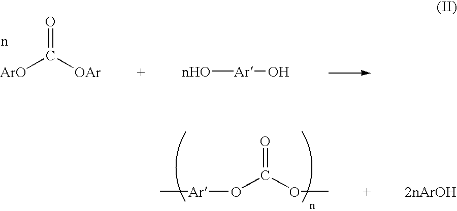
- diaryl carbonates may be generated by the reaction of a dialkyl carbonate with an aryl hydroxide (see Scheme I, above).
- the diaryl carbonate may in turn be reacted with a dihydric phenol to form a polycarbonate (see Scheme II, above).
- dimethyl carbonate prepared according to the method may be reacted with phenoxide to form diphenyl carbonate, which in turn may be reacted with bisphenol A to form a polycarbonate.
- a plant according to simplified FIG. 2 was built and operated to produce dimethyl carbonate. Corrosion damage was observed in and downstream of the azeotropic column 180 . After extensive experimentation, it was determined that the corrosion damage was caused by methyl chloroformate passing through the acid separation column. Specifically, methyl chloroformate was found to be present in the azeotrope column 180 at a concentration of 300 parts per million (ppm) by weight.
- Example 2 32 milliliters (mL) of dimethyl carbonate, 10 mL of dimethyl carbonate containing 50 mg of a biphenyl internal standard 63 mL of methanol, and 5 ml of water were added to a 250 mL flask equipped with a thermometer, a condenser, and a port for sampling. (Toluene may be used instead of the methanol/water solution.) The resultant homogeneous solution was placed in an oil bath and the temperature of the solution was held constant at 50° C.
- chloride concentration is equal to the methyl chloroformate concentration because each equivalent of methyl chloroformate liberates one equivalent of ionic chloride upon derivatization.
- gas chromatography can be used for direct analysis of the N,N′-diisobutyl methyl carbamate using an internal standard.
- Example 2 corresponds to the case described above.
- Example 3 has added hydrochloric acid that is generally present in the authentic reaction mixture.
- Example 4 the effect of a small amount of sodium bicarbonate was tested.
- Example 5 the ratio of dimethyl carbonate to methanol was held constant, but the amount of water was increased from 5% to 10%. The results are summarized below in Table I.
- FIG. 2 For Comparative Example 2, a dimethyl carbonate plant according to simplified FIG. 2 was operated according to the conditions described in Table III, below. This plant was similar to that shown in more detail in FIG. 1 , with the exception that the first heat exchanger 140 and the fluid passageway 110 were absent. Corrosion was observed in and downstream of the azeotrope column 180 . Next, this plant was modified to include the first heat exchanger 140 and two holding vessels 120 were added to increase residence time (i.e., FIG. 3 configuration).
- FIG. 10 presents measurements of residual ionic chlorides found in samples taken from the bottom of the azeotrope column 180 , comparing the FIG. 2 and FIG. 3 configurations, each over time.
- Residual chlorides were determined by titration using a silver nitrate solution, as described above.
- the data for the FIG. 2 configuration have an average of 671 ppm chloride with a standard deviation of 370 ppm chloride, whereas the data for the FIG. 3 configuration have an average of 35 ppm chloride and a standard deviation of 25 ppm chloride.
- the data thus show a dramatic reduction in chloride levels for the FIG. 3 configuration vs. the FIG. 2 configuration. It is predicted this reduction would be even greater for the configurations according to FIGS. 4 and 6 , in which four holding vessels 120 are used to provide a residence time of four hours at 70° C.
- FIG. 11 presents measurements of methyl chloroformate concentration entering and exiting the fluid passageway 110 of the FIG.
- FIG. 3 (comparison) 671 ⁇ 370
- FIG. 2 (invention) 35 ⁇ 25
Abstract
Description


It may also be preferred to remove the alkyl chloroformate without passing the liquid fraction through an ion exchange resin, because such resins are expensive to install and operate. It may be preferred to remove at least about 50 percent, more preferably at least about 90 percent, yet more preferably at least about 95 percent, even more preferably at least about 99 percent, of the alkyl chloroformate from the liquid fraction. In one embodiment, it may be preferred to reduce the alkyl chloroformate concentration in the liquid fraction to less than about 500 ppm, more preferably less than about 100 ppm, yet more preferably less than about 30 ppm. In any of these embodiments, it may be preferred to remove less than about 10%, more preferably less than about 5%, yet more preferably less than about 1%, of the dialkyl carbonate. Although the method may be described as “removing less than about 10% of said dialkyl carbonate”, it will be understood that the concentration of dialkyl carbonate need not be reduced and may even increase. For example, the concentration of dialkyl carbonate may increase if the Scheme V reaction of alkyl chloroformate with methanol forms dialkyl carbonate faster than dialkyl carbonate decomposes due to other reactions.
−r MCF=(k 1[H2O]+k 2[MeOH])[MCF] (1)
where rMCF is the rate of change of the moles of methyl chloroformate (MCF) per unit volume, [H2O], [MeOH], and [MCF] are the instantaneous concentrations of water, methanol, and methyl chloroforrnate, respectively, in moles per unit volume, and k1 and k2 are rate constants that vary with temperature according to equations (2) and (3), respectively
k 1 =k 1 0 e −6381/T (2)
k 2 =k 2 0 e −7673/T (3)
where k1 0=2.09×10⁹ mL/mol-min, k2 0=4.14×10¹⁰ mL/mol-min, and T is the temperature in degrees kelvin.
−d[MCF]/dt=(k 1[H2O]+k 2[MeOH])[MCF] (4)
where t is time in minutes. In a batch process, at least about 10% of the methyl chloroformate may be removed by maintaining the liquid fraction under conditions comprising a water concentration ([H2O]), a methanol concentration ([MeOH]), a temperature (T), and a time (t), such that a parameter X according to the equation (5)
X=exp{−[(2.09×10⁹)e (−6381/T)[H2O]+(4.14×1010)e (−7673/T)[MeOH]]t} (5)
has a value less than about 0.9, wherein the water concentration and the methanol concentration are expressed in moles per milliliter, the temperature is expressed in degrees Kelvin, and the time is expressed in minutes. The value of X may preferably be less than about 0.5, more preferably less than about 0.2, yet more preferably be less than about 0.1, even more preferably less than about 0.05, still more preferably less than about 0.01. The water concentration may be about 0.1 to about 50 moles per liter (mol/L). Within this range, the water concentration may preferably be at least about 0.5 mol/L, more preferably at least about 1 mol/L. Also within this range, the water concentration may preferably be up to about 30 mol/L, more preferably up to about 20 mol/L, yet more preferably up to about 10 mol/L, even more preferably up to about 5 mol/L. The methanol concentration may be about 1 to about 25 mol/L. Within this range, the methanol concentration may preferably be at least about 5 mol/L, more preferably at least about 10 mol/L. Also within this range, the methanol concentration may preferably be up to about 20 mol/L, more preferably up to about 18 mol/L. The time may be about 0.5 hour to about 10 hours. Within this range, the time may preferably be at least about 1 hours, more preferably at least about 2 hours. Also within this range, the time may preferably be up to about 8 hours, more preferably up to about 6 hours. The temperature may be about 30 to about 130° C. Within this range, the temperature may preferably be at least about 40° C., more preferably at least about 50° C., yet more preferably at least about 60° C. Also within this range, the temperature may preferably be up to about 110° C., more preferably up to about 100° C., yet more preferably up to about 90° C.
[MCF]tR=[MCF]t=0(1/(1+kt R)) (6)
where [MCF]t=0 is the initial concentration of methyl chloroformate in moles per milliliter, tR is the residence time in minutes, and k is given by equation (7)
k=k 1[H2O]+k 2[MeOH] (7)
where k1, k2, [H2O], and [MeOH] are as defined above. The residence time tR may be defined as the average time spent by a molecule in the
Z=[MCF]t=0exp{−[(2.09×10⁹)e (−6381/T)[H2O]+(4.14×1010)e (−7673/T)[MeOH]]t} (8)
has a value less than about 5×10⁻⁶, preferably less than about 1×10⁻⁶, more preferably less than about 5×10⁻⁷, even more preferably less than about 5×10⁻⁸, wherein the initial concentration of methyl chloroformate, the water concentration, and the methanol concentration are expressed in moles per milliliter, the temperature is expressed in degrees Kelvin, and the time is expressed in minutes. The temperature, time, methanol concentration, and water concentration in this expression are as described above. The initial concentration of methyl chloroformate will depend on the reactor conditions, but it is typically about 5×10⁻³ moles per liter to about 5×10⁻¹ moles per liter. Within this range, the initial concentration of methyl chloroformate may be at least about 1×10⁻² moles per liter. Also within this range, the initial concentration of methyl chloroformate may be up to about 1×10⁻¹ moles per liter.
X=exp{−[(2.09×10⁹)e (−6381/T)[H2O]t=0+(4.14×1010)e (−7673/T)[MeOH]t=0 ]t} (9)
has a value less than about 0.9, and a parameter Y calculated according to the equation (10)
has a value of at least about 0.9, wherein the initial dimethyl carbonate concentration, the initial water concentration, the initial methanol concentration, and the initial hydrochloric acid concentration are expressed in moles per milliliter, the temperature is expressed in degrees Kelvin, and the time is expressed in minutes. The value of Y may preferably be at least about 0.95, more preferably at least about 0.99. Suitable analytical techniques to determine initial concentrations of water, methanol, hydrochloric acid, and dimethyl carbonate in reaction mixtures are well known in the art. The term “initial concentration” refers to the concentration of a species before intentional removal of alkyl chloroformate. The initial water and methanol concentrations are the same as the water and methanol concentrations described above (under typical reaction conditions, the water and methanol concentrations are large are essentially constant during alkyl chloroformate removal). The initial dimethyl carbonate concentration may be about 0.5 to about 10 mol/L. Within this range, the initial dimethyl carbonate concentration may preferably be at least about 1 mol/L, more preferably at least about 2 mol/L. Also within this range, the initial dimethyl carbonate concentration may preferably be up to about 8 mol/L, more preferably up to about 6 mol/L. The concentration of HCl in the liquid fraction will depend on the type and concentration of catalyst employed. The initial hydrochloric acid concentration will depend on the type and amount of catalyst, but it is typically about 1×10⁻³ to about 2×10⁻¹ moles per liter. Within this range, the initial hydrochloric acid concentration may preferably be at least about 5×10⁻³, more preferably at least about 1×10⁻² mol/L. Also within this range, the initial hydrochloric acid concentration may preferably be up to about 1×10⁻¹ more preferably up to about 7×10⁻² mol/L.
| TABLE I | ||||||
| DMC | MeOH | H2O | Temp | |||
| (wt %) | (wt %) | (wt %) | (° C.) | k (min−1) | ||
| Ex. 2 | 45 | 50 | 5 | 50 | 0.043 | ||
| Ex. 3* | 45 | 50 | 5 | 50 | 0.043 | ||
| Ex. 4** | 45 | 50 | 5 | 50 | 0.480 | ||
| Ex. 5*** | 43 | 47 | 10 | 50 | 0.055 | ||
| *Identical to Ex. 2, except that it also had 1000 ppm of HCl, which is similar to the effluent from the |
|||||||
| **Identical to Ex. 2, except that 1.6 eq. of NaHCO3 relative to the 1000 ppm MCF were added. | |||||||
| ***Identical to Ex. 2, except that the % water was increased by 10%, but the ratio of DMC/MeOH was not changed, just reduced overall. | |||||||
| TABLE II | |||
| Chloride Concentration (ppm) | |||
| Time (h) | Ex. 6 | Comp. Ex. 1 |
| 0 | 374 | 189 |
| 2 | 408 | 312 |
| 4 | 374 | 339 |
| 8 | 372 | 368 |
| 10 | 372 | 357 |
| 25 | 381 | 368 |
| TABLE III | ||
| Control | ||
| Ex. 7 (FIG. 2 | Ex. 2 (FIG. 3 | |
| Conditions | Configuration) | Configuration) |
| Mass Ratio MeOH/O2/CO | 0.7/0.06/1 | 0.7/0.06/1 |
| Catalyst Content | Fixed | Fixed |
| Reaction Temperature (° C.) | 133 | 133 |
| Reaction Pressure (barg) | 23 | 23 |
| Temp. of |
60 | — |
| Heater (° C.) | ||
| Temp. of |
90 | 90 |
| Vaporizer (° C.) | ||
| Residence Time between flash | 2 | 0.03 |
| vessel and acid column, excluding | ||
| both (hours) | ||
| TABLE IV | |||
| average chloride | |||
| concentration ± standard | |||
| Configuration | deviation (ppm) | ||
| FIG. 3 (comparison) | 671 ± 370 | ||
| FIG. 2 (invention) | 35 ± 25 | ||
Claims (15)
Priority Applications (3)
| Application Number | Priority Date | Filing Date | Title |
|---|---|---|---|
| US10/227,111 US7351848B2 (en) | 2001-08-14 | 2002-08-23 | Method and apparatus for preparing a dialkyl carbonate, and its use in the preparation of diaryl carbonates and polycarbonates |
| US10/740,578 US20050033078A1 (en) | 2001-08-14 | 2003-12-22 | Method and apparatus for preparing a dialkyl carbonate, and its use in the preparation of diaryl carbonates and polycarbonates |
| US10/917,222 US20050019226A1 (en) | 2001-08-14 | 2004-08-12 | Apparatus for preparing a dialkyl carbonate |
Applications Claiming Priority (2)
| Application Number | Priority Date | Filing Date | Title |
|---|---|---|---|
| US09/682,286 US7345187B2 (en) | 2001-08-14 | 2001-08-14 | Method and apparatus for preparing a dialkyl carbonate, and its use in the preparation of diaryl carbonates and polycarbonates |
| US10/227,111 US7351848B2 (en) | 2001-08-14 | 2002-08-23 | Method and apparatus for preparing a dialkyl carbonate, and its use in the preparation of diaryl carbonates and polycarbonates |
Related Parent Applications (1)
| Application Number | Title | Priority Date | Filing Date |
|---|---|---|---|
| US09/682,286 Continuation-In-Part US7345187B2 (en) | 2001-08-14 | 2001-08-14 | Method and apparatus for preparing a dialkyl carbonate, and its use in the preparation of diaryl carbonates and polycarbonates |
Related Child Applications (2)
| Application Number | Title | Priority Date | Filing Date |
|---|---|---|---|
| US10/740,578 Continuation US20050033078A1 (en) | 2001-08-14 | 2003-12-22 | Method and apparatus for preparing a dialkyl carbonate, and its use in the preparation of diaryl carbonates and polycarbonates |
| US10/917,222 Division US20050019226A1 (en) | 2001-08-14 | 2004-08-12 | Apparatus for preparing a dialkyl carbonate |
Publications (2)
| Publication Number | Publication Date |
|---|---|
| US20030153782A1 US20030153782A1 (en) | 2003-08-14 |
| US7351848B2 true US7351848B2 (en) | 2008-04-01 |
Family
ID=24739029
Family Applications (5)
| Application Number | Title | Priority Date | Filing Date |
|---|---|---|---|
| US09/682,286 Expired - Fee Related US7345187B2 (en) | 2001-08-14 | 2001-08-14 | Method and apparatus for preparing a dialkyl carbonate, and its use in the preparation of diaryl carbonates and polycarbonates |
| US10/227,111 Expired - Fee Related US7351848B2 (en) | 2001-08-14 | 2002-08-23 | Method and apparatus for preparing a dialkyl carbonate, and its use in the preparation of diaryl carbonates and polycarbonates |
| US10/740,578 Abandoned US20050033078A1 (en) | 2001-08-14 | 2003-12-22 | Method and apparatus for preparing a dialkyl carbonate, and its use in the preparation of diaryl carbonates and polycarbonates |
| US10/740,801 Abandoned US20050033079A1 (en) | 2001-08-14 | 2003-12-22 | Method and apparatus for preparing a dialkyl carbonate, and its use in the preparation of diaryl carbonates and polycarbonates |
| US10/917,222 Abandoned US20050019226A1 (en) | 2001-08-14 | 2004-08-12 | Apparatus for preparing a dialkyl carbonate |
Family Applications Before (1)
| Application Number | Title | Priority Date | Filing Date |
|---|---|---|---|
| US09/682,286 Expired - Fee Related US7345187B2 (en) | 2001-08-14 | 2001-08-14 | Method and apparatus for preparing a dialkyl carbonate, and its use in the preparation of diaryl carbonates and polycarbonates |
Family Applications After (3)
| Application Number | Title | Priority Date | Filing Date |
|---|---|---|---|
| US10/740,578 Abandoned US20050033078A1 (en) | 2001-08-14 | 2003-12-22 | Method and apparatus for preparing a dialkyl carbonate, and its use in the preparation of diaryl carbonates and polycarbonates |
| US10/740,801 Abandoned US20050033079A1 (en) | 2001-08-14 | 2003-12-22 | Method and apparatus for preparing a dialkyl carbonate, and its use in the preparation of diaryl carbonates and polycarbonates |
| US10/917,222 Abandoned US20050019226A1 (en) | 2001-08-14 | 2004-08-12 | Apparatus for preparing a dialkyl carbonate |
Country Status (7)
| Country | Link |
|---|---|
| US (5) | US7345187B2 (en) |
| EP (1) | EP1419131B1 (en) |
| JP (1) | JP2005520784A (en) |
| KR (1) | KR20040021701A (en) |
| CN (1) | CN100439318C (en) |
| TW (1) | TW584630B (en) |
| WO (1) | WO2003016257A1 (en) |
Families Citing this family (8)
| Publication number | Priority date | Publication date | Assignee | Title |
|---|---|---|---|---|
| US7345187B2 (en) * | 2001-08-14 | 2008-03-18 | General Electric Company | Method and apparatus for preparing a dialkyl carbonate, and its use in the preparation of diaryl carbonates and polycarbonates |
| US6784277B2 (en) * | 2001-08-14 | 2004-08-31 | General Electric Company | Method for preparing a dialkyl carbonate, and its use in the preparation of diaryl carbonates and polycarbonates |
| US7514521B2 (en) * | 2001-08-14 | 2009-04-07 | Sabic Innovative Plastics Ip B.V. | Method for preparing a dialkyl carbonate, and its use in the preparation of diaryl carbonates and polycarbonates |
| US6977308B2 (en) * | 2002-06-25 | 2005-12-20 | General Electric Company | Method and apparatus for preparing a dialkyl carbonate |
| US20050277782A1 (en) * | 2003-12-22 | 2005-12-15 | Enitecnologie S.P.A. | Method for removal of acid contaminants in a process for the synthesis of dimethyl carbonate |
| US7622602B2 (en) * | 2005-10-12 | 2009-11-24 | Sabic Innovative Plastics Ip B.V. | Method for preparing a dialkyl carbonate, and its use in the preparation of diaryl carbonates and polycarbonates |
| CN107735348B (en) * | 2015-07-08 | 2020-02-14 | 因温特奥股份公司 | Elevator operating panel for providing options to indicate additional floor information |
| CN112457194A (en) * | 2020-11-24 | 2021-03-09 | 上海诺哈尔化工技术有限公司 | Dechlorination refining process for preparing crude dimethyl carbonate by gas-phase carbonyl method |
Citations (16)
| Publication number | Priority date | Publication date | Assignee | Title |
|---|---|---|---|---|
| US2517965A (en) | 1948-03-23 | 1950-08-08 | Pittsburgh Plate Glass Co | Purification of carbonic acid esters |
| US3153008A (en) | 1955-07-05 | 1964-10-13 | Gen Electric | Aromatic carbonate resins and preparation thereof |
| US4182726A (en) | 1974-06-25 | 1980-01-08 | Snamprogetti, S.P.A. | Process for the preparation of aromatic carbonates |
| US4218391A (en) | 1976-09-30 | 1980-08-19 | Anic, S.P.A. | Method for the preparation of esters of carbonic acid |
| US4318862A (en) | 1979-12-04 | 1982-03-09 | Anic S.P.A. | Process for producing dimethylcarbonate |
| US4360659A (en) | 1981-05-06 | 1982-11-23 | General Electric Company | Non-catalyzed interfacial polycondensation polycarbonate process |
| US5210269A (en) | 1990-06-04 | 1993-05-11 | Enichem Synthesis S.P.A. | Process for producing dimethyl carbonate |
| JPH0692905A (en) | 1991-07-26 | 1994-04-05 | Nippon Polyurethane Ind Co Ltd | Purification of dialkyl carbonate |
| EP0634390A1 (en) | 1993-07-15 | 1995-01-18 | ENICHEM SYNTHESIS S.p.A. | Method for removing acid and saline contaminants from a gaseous stream leaving a dimethylcarbonate synthesis reactor |
| US5536864A (en) | 1990-06-04 | 1996-07-16 | Enichem Synthesis S.P.A. | Process for producing dimethyl carbonate and apparatus suitable for such purpose |
| US5599965A (en) | 1993-07-30 | 1997-02-04 | Bayer Aktiengesellschaft | Process for the preparation of dialky carbonates |
| US5686644A (en) | 1991-09-23 | 1997-11-11 | Enichem Synthesis S.P.A. | Procedure for the production of alkyl carbonates |
| US5685957A (en) | 1994-06-03 | 1997-11-11 | Enichem Synthesis S.P.A. | Method for removing acidic and salt impurities from an aqueous condensed phase containing dimethylcarbonate |
| US5780663A (en) | 1996-04-17 | 1998-07-14 | Jgc Corporation | Process for producing carbonic acid diester |
| US5869729A (en) | 1993-05-21 | 1999-02-09 | Ube Industries, Ltd. | Method of producing an ester compound |
| WO2003016256A1 (en) | 2001-08-14 | 2003-02-27 | General Electric Company | Method for preparing a dialkyl carbonate, and its use in the preparation of diaryl carbonates and polycarbonates |
Family Cites Families (8)
| Publication number | Priority date | Publication date | Assignee | Title |
|---|---|---|---|---|
| DE3016876A1 (en) * | 1980-05-02 | 1981-11-05 | Krupp-Koppers Gmbh, 4300 Essen | METHOD FOR PRODUCING SYNTHESIS GAS |
| US5206409A (en) * | 1988-10-19 | 1993-04-27 | Enichem Synthesis, S.P.A. | Process for preparing di-alkyl carbonates |
| US5220782A (en) * | 1991-10-23 | 1993-06-22 | Bechtel Group, Inc. | Efficient low temperature solvent removal of acid gases |
| US5387708A (en) * | 1993-12-10 | 1995-02-07 | The Dow Chemical Company | Production of dialkyl carbonates using copper catalysts |
| US6458914B2 (en) * | 2000-06-28 | 2002-10-01 | General Electric Company | Method for manufacturing dialkyl carbonate |
| US6774256B2 (en) * | 2001-06-22 | 2004-08-10 | Exxonmobil Chemical Patents Inc. | Low corrosive integrated process for preparing dialkyl carbonates |
| US6784277B2 (en) * | 2001-08-14 | 2004-08-31 | General Electric Company | Method for preparing a dialkyl carbonate, and its use in the preparation of diaryl carbonates and polycarbonates |
| US7345187B2 (en) * | 2001-08-14 | 2008-03-18 | General Electric Company | Method and apparatus for preparing a dialkyl carbonate, and its use in the preparation of diaryl carbonates and polycarbonates |
-
2001
- 2001-08-14 US US09/682,286 patent/US7345187B2/en not_active Expired - Fee Related
-
2002
- 2002-07-30 CN CNB028203216A patent/CN100439318C/en not_active Expired - Fee Related
- 2002-07-30 WO PCT/US2002/024364 patent/WO2003016257A1/en active Search and Examination
- 2002-07-30 EP EP20020756863 patent/EP1419131B1/en not_active Expired - Lifetime
- 2002-07-30 JP JP2003521186A patent/JP2005520784A/en active Pending
- 2002-07-30 KR KR10-2004-7002219A patent/KR20040021701A/en not_active Application Discontinuation
- 2002-08-01 TW TW091117318A patent/TW584630B/en not_active IP Right Cessation
- 2002-08-23 US US10/227,111 patent/US7351848B2/en not_active Expired - Fee Related
-
2003
- 2003-12-22 US US10/740,578 patent/US20050033078A1/en not_active Abandoned
- 2003-12-22 US US10/740,801 patent/US20050033079A1/en not_active Abandoned
-
2004
- 2004-08-12 US US10/917,222 patent/US20050019226A1/en not_active Abandoned
Patent Citations (17)
| Publication number | Priority date | Publication date | Assignee | Title |
|---|---|---|---|---|
| US2517965A (en) | 1948-03-23 | 1950-08-08 | Pittsburgh Plate Glass Co | Purification of carbonic acid esters |
| US3153008A (en) | 1955-07-05 | 1964-10-13 | Gen Electric | Aromatic carbonate resins and preparation thereof |
| US4182726A (en) | 1974-06-25 | 1980-01-08 | Snamprogetti, S.P.A. | Process for the preparation of aromatic carbonates |
| US4218391A (en) | 1976-09-30 | 1980-08-19 | Anic, S.P.A. | Method for the preparation of esters of carbonic acid |
| US4318862A (en) | 1979-12-04 | 1982-03-09 | Anic S.P.A. | Process for producing dimethylcarbonate |
| US4360659A (en) | 1981-05-06 | 1982-11-23 | General Electric Company | Non-catalyzed interfacial polycondensation polycarbonate process |
| US5536864A (en) | 1990-06-04 | 1996-07-16 | Enichem Synthesis S.P.A. | Process for producing dimethyl carbonate and apparatus suitable for such purpose |
| US5210269A (en) | 1990-06-04 | 1993-05-11 | Enichem Synthesis S.P.A. | Process for producing dimethyl carbonate |
| JPH0692905A (en) | 1991-07-26 | 1994-04-05 | Nippon Polyurethane Ind Co Ltd | Purification of dialkyl carbonate |
| US5686644A (en) | 1991-09-23 | 1997-11-11 | Enichem Synthesis S.P.A. | Procedure for the production of alkyl carbonates |
| US5869729A (en) | 1993-05-21 | 1999-02-09 | Ube Industries, Ltd. | Method of producing an ester compound |
| US5527943A (en) | 1993-07-15 | 1996-06-18 | Enichem Synthesis S.P.A. | Method for removing acid and saline contaminants from a gaseous stream leaving a dimethylcarbonate synthesis reactor |
| EP0634390A1 (en) | 1993-07-15 | 1995-01-18 | ENICHEM SYNTHESIS S.p.A. | Method for removing acid and saline contaminants from a gaseous stream leaving a dimethylcarbonate synthesis reactor |
| US5599965A (en) | 1993-07-30 | 1997-02-04 | Bayer Aktiengesellschaft | Process for the preparation of dialky carbonates |
| US5685957A (en) | 1994-06-03 | 1997-11-11 | Enichem Synthesis S.P.A. | Method for removing acidic and salt impurities from an aqueous condensed phase containing dimethylcarbonate |
| US5780663A (en) | 1996-04-17 | 1998-07-14 | Jgc Corporation | Process for producing carbonic acid diester |
| WO2003016256A1 (en) | 2001-08-14 | 2003-02-27 | General Electric Company | Method for preparing a dialkyl carbonate, and its use in the preparation of diaryl carbonates and polycarbonates |
Non-Patent Citations (8)
| Title |
|---|
| Anonymous, GE Licenses Enimont Polycarb Know-How, European Chemical News, Nov. 13, 1989, p. 44. |
| Cassar, Dimethylcarbonate: a New Intermediate for a Cleaner Future, Chim. Ind. (Milan) (1990), vol. 72, No. 1, pp. 18-22. |
| Mauri et al., Dimethyl Carbonate: a New Building Block for Organic Chemicals Production, Quad. Ing. Chim. Ital. (1985), vol. 21, No. 1-3, pp. 6-12. |
| Mauri, et al. "Dimethyl carbonate: a new building block for organic chemicals production". Ing. Chim. Ital., V. 21, N. 1-3, Gen- Mar. 1985 pp. 6-12. |
| U.S. Appl. No. 09/682,284, filed Aug. 14, 2001, Boden, et al. |
| U.S. Appl. No. 09/682,285, filed Aug. 14, 2001, Boden, et al. |
| U.S. Appl. No. 09/682,286, filed Aug. 14, 2001, Boden, et al. |
| U.S. Appl. No. 10/250,067, filed Jun. 2, 2003, Boden, et al. |
Also Published As
| Publication number | Publication date |
|---|---|
| US20030060650A1 (en) | 2003-03-27 |
| WO2003016257A1 (en) | 2003-02-27 |
| EP1419131A1 (en) | 2004-05-19 |
| US7345187B2 (en) | 2008-03-18 |
| CN100439318C (en) | 2008-12-03 |
| EP1419131B1 (en) | 2015-05-20 |
| CN1568301A (en) | 2005-01-19 |
| KR20040021701A (en) | 2004-03-10 |
| TW584630B (en) | 2004-04-21 |
| US20050033079A1 (en) | 2005-02-10 |
| US20050019226A1 (en) | 2005-01-27 |
| US20050033078A1 (en) | 2005-02-10 |
| US20030153782A1 (en) | 2003-08-14 |
| JP2005520784A (en) | 2005-07-14 |
Similar Documents
| Publication | Publication Date | Title |
|---|---|---|
| JP4020440B2 (en) | Process for the continuous production of diaryl carbonates | |
| US6784277B2 (en) | Method for preparing a dialkyl carbonate, and its use in the preparation of diaryl carbonates and polycarbonates | |
| US7514521B2 (en) | Method for preparing a dialkyl carbonate, and its use in the preparation of diaryl carbonates and polycarbonates | |
| US7351848B2 (en) | Method and apparatus for preparing a dialkyl carbonate, and its use in the preparation of diaryl carbonates and polycarbonates | |
| US7462336B2 (en) | Apparatus for preparing a dialkyl carbonate | |
| US5685957A (en) | Method for removing acidic and salt impurities from an aqueous condensed phase containing dimethylcarbonate | |
| JP3970627B2 (en) | Method for producing diphenyl carbonate and method for producing aromatic polycarbonate | |
| WO2003016258A1 (en) | Method for preparing a dialkyl carbonate, and its use in the preparation of diaryl carbonates and polycarbonates | |
| US20050277782A1 (en) | Method for removal of acid contaminants in a process for the synthesis of dimethyl carbonate | |
| EP2121563B1 (en) | Process for manufacturing dimethyl carbonate |
Legal Events
| Date | Code | Title | Description |
|---|---|---|---|
| AS | Assignment |
Owner name: GENERAL ELECTRIC COMPANY, NEW YORK Free format text: ASSIGNMENT OF ASSIGNORS INTEREST;ASSIGNORS:BODEN, EUGENE PAULING;KAILASAM, GANESH;LEWIS, LARRY NEIL;AND OTHERS;REEL/FRAME:013237/0606;SIGNING DATES FROM 20020813 TO 20020819 |
|
| FEPP | Fee payment procedure |
Free format text: PAYOR NUMBER ASSIGNED (ORIGINAL EVENT CODE: ASPN); ENTITY STATUS OF PATENT OWNER: LARGE ENTITY |
|
| STCF | Information on status: patent grant |
Free format text: PATENTED CASE |
|
| AS | Assignment |
Owner name: SABIC INNOVATIVE PLASTICS IP B.V., NETHERLANDS Free format text: ASSIGNMENT OF ASSIGNORS INTEREST;ASSIGNOR:GENERAL ELECTRIC COMPANY;REEL/FRAME:020985/0551 Effective date: 20070831 Owner name: SABIC INNOVATIVE PLASTICS IP B.V.,NETHERLANDS Free format text: ASSIGNMENT OF ASSIGNORS INTEREST;ASSIGNOR:GENERAL ELECTRIC COMPANY;REEL/FRAME:020985/0551 Effective date: 20070831 |
|
| AS | Assignment |
Owner name: CITIBANK, N.A., AS COLLATERAL AGENT, NEW YORK Free format text: SECURITY AGREEMENT;ASSIGNOR:SABIC INNOVATIVE PLASTICS IP B.V.;REEL/FRAME:021423/0001 Effective date: 20080307 Owner name: CITIBANK, N.A., AS COLLATERAL AGENT,NEW YORK Free format text: SECURITY AGREEMENT;ASSIGNOR:SABIC INNOVATIVE PLASTICS IP B.V.;REEL/FRAME:021423/0001 Effective date: 20080307 |
|
| FPAY | Fee payment |
Year of fee payment: 4 |
|
| AS | Assignment |
Owner name: SABIC INNOVATIVE PLASTICS IP B.V., NETHERLANDS Free format text: RELEASE BY SECURED PARTY;ASSIGNOR:CITIBANK, N.A.;REEL/FRAME:032459/0798 Effective date: 20140312 |
|
| FPAY | Fee payment |
Year of fee payment: 8 |
|
| AS | Assignment |
Owner name: SABIC GLOBAL TECHNOLOGIES B.V., NETHERLANDS Free format text: CHANGE OF NAME;ASSIGNOR:SABIC INNOVATIVE PLASTICS IP B.V.;REEL/FRAME:038883/0906 Effective date: 20140402 |
|
| FEPP | Fee payment procedure |
Free format text: MAINTENANCE FEE REMINDER MAILED (ORIGINAL EVENT CODE: REM.); ENTITY STATUS OF PATENT OWNER: LARGE ENTITY |
|
| LAPS | Lapse for failure to pay maintenance fees |
Free format text: PATENT EXPIRED FOR FAILURE TO PAY MAINTENANCE FEES (ORIGINAL EVENT CODE: EXP.); ENTITY STATUS OF PATENT OWNER: LARGE ENTITY |
|
| STCH | Information on status: patent discontinuation |
Free format text: PATENT EXPIRED DUE TO NONPAYMENT OF MAINTENANCE FEES UNDER 37 CFR 1.362 |
|
| FP | Lapsed due to failure to pay maintenance fee |
Effective date: 20200401 |