US7321820B2 - Model-based inlet air dynamics state characterization - Google Patents
Model-based inlet air dynamics state characterization Download PDFInfo
- Publication number
- US7321820B2 US7321820B2 US11/342,925 US34292506A US7321820B2 US 7321820 B2 US7321820 B2 US 7321820B2 US 34292506 A US34292506 A US 34292506A US 7321820 B2 US7321820 B2 US 7321820B2
- Authority
- US
- United States
- Prior art keywords
- egr
- engine
- fuel injection
- injection timing
- error
- Prior art date
- Legal status (The legal status is an assumption and is not a legal conclusion. Google has not performed a legal analysis and makes no representation as to the accuracy of the status listed.)
- Expired - Lifetime, expires
Links
Images


Classifications
-
- F—MECHANICAL ENGINEERING; LIGHTING; HEATING; WEAPONS; BLASTING
- F02—COMBUSTION ENGINES; HOT-GAS OR COMBUSTION-PRODUCT ENGINE PLANTS
- F02D—CONTROLLING COMBUSTION ENGINES
- F02D41/00—Electrical control of supply of combustible mixture or its constituents
- F02D41/0025—Controlling engines characterised by use of non-liquid fuels, pluralities of fuels, or non-fuel substances added to the combustible mixtures
- F02D41/0047—Controlling exhaust gas recirculation [EGR]
- F02D41/0065—Specific aspects of external EGR control
- F02D41/0072—Estimating, calculating or determining the EGR rate, amount or flow
-
- F—MECHANICAL ENGINEERING; LIGHTING; HEATING; WEAPONS; BLASTING
- F02—COMBUSTION ENGINES; HOT-GAS OR COMBUSTION-PRODUCT ENGINE PLANTS
- F02B—INTERNAL-COMBUSTION PISTON ENGINES; COMBUSTION ENGINES IN GENERAL
- F02B47/00—Methods of operating engines involving adding non-fuel substances or anti-knock agents to combustion air, fuel, or fuel-air mixtures of engines
- F02B47/04—Methods of operating engines involving adding non-fuel substances or anti-knock agents to combustion air, fuel, or fuel-air mixtures of engines the substances being other than water or steam only
- F02B47/08—Methods of operating engines involving adding non-fuel substances or anti-knock agents to combustion air, fuel, or fuel-air mixtures of engines the substances being other than water or steam only the substances including exhaust gas
-
- F—MECHANICAL ENGINEERING; LIGHTING; HEATING; WEAPONS; BLASTING
- F02—COMBUSTION ENGINES; HOT-GAS OR COMBUSTION-PRODUCT ENGINE PLANTS
- F02D—CONTROLLING COMBUSTION ENGINES
- F02D41/00—Electrical control of supply of combustible mixture or its constituents
- F02D41/30—Controlling fuel injection
- F02D41/32—Controlling fuel injection of the low pressure type
- F02D41/34—Controlling fuel injection of the low pressure type with means for controlling injection timing or duration
- F02D41/345—Controlling injection timing
-
- F—MECHANICAL ENGINEERING; LIGHTING; HEATING; WEAPONS; BLASTING
- F02—COMBUSTION ENGINES; HOT-GAS OR COMBUSTION-PRODUCT ENGINE PLANTS
- F02M—SUPPLYING COMBUSTION ENGINES IN GENERAL WITH COMBUSTIBLE MIXTURES OR CONSTITUENTS THEREOF
- F02M26/00—Engine-pertinent apparatus for adding exhaust gases to combustion-air, main fuel or fuel-air mixture, e.g. by exhaust gas recirculation [EGR] systems
- F02M26/02—EGR systems specially adapted for supercharged engines
- F02M26/04—EGR systems specially adapted for supercharged engines with a single turbocharger
- F02M26/05—High pressure loops, i.e. wherein recirculated exhaust gas is taken out from the exhaust system upstream of the turbine and reintroduced into the intake system downstream of the compressor
-
- F—MECHANICAL ENGINEERING; LIGHTING; HEATING; WEAPONS; BLASTING
- F02—COMBUSTION ENGINES; HOT-GAS OR COMBUSTION-PRODUCT ENGINE PLANTS
- F02M—SUPPLYING COMBUSTION ENGINES IN GENERAL WITH COMBUSTIBLE MIXTURES OR CONSTITUENTS THEREOF
- F02M26/00—Engine-pertinent apparatus for adding exhaust gases to combustion-air, main fuel or fuel-air mixture, e.g. by exhaust gas recirculation [EGR] systems
- F02M26/13—Arrangement or layout of EGR passages, e.g. in relation to specific engine parts or for incorporation of accessories
- F02M26/22—Arrangement or layout of EGR passages, e.g. in relation to specific engine parts or for incorporation of accessories with coolers in the recirculation passage
- F02M26/23—Layout, e.g. schematics
-
- Y—GENERAL TAGGING OF NEW TECHNOLOGICAL DEVELOPMENTS; GENERAL TAGGING OF CROSS-SECTIONAL TECHNOLOGIES SPANNING OVER SEVERAL SECTIONS OF THE IPC; TECHNICAL SUBJECTS COVERED BY FORMER USPC CROSS-REFERENCE ART COLLECTIONS [XRACs] AND DIGESTS
- Y02—TECHNOLOGIES OR APPLICATIONS FOR MITIGATION OR ADAPTATION AGAINST CLIMATE CHANGE
- Y02T—CLIMATE CHANGE MITIGATION TECHNOLOGIES RELATED TO TRANSPORTATION
- Y02T10/00—Road transport of goods or passengers
- Y02T10/10—Internal combustion engine [ICE] based vehicles
- Y02T10/40—Engine management systems
Definitions
- the present invention relates to internal combustion engines, and more particularly to a combustion control for reducing engine emissions.
- Internal combustion engines combust an air and fuel mixture to generate drive torque. More specifically, air is drawn into the engine and is mixed with fuel. The air and fuel mixture is combusted within cylinders to drive a crankshaft, producing drive torque. Mass airflow into the engine and the quantity of fuel injected determine the amount of drive torque generated.
- EGR exhaust gas recirculation
- the EGR system includes an EGR valve that regulates an amount of exhaust gas that is circulated back to the intake manifold. The additional exhaust gas affects the amount of engine air intake through the throttle. EGR is the most efficient means to reduce overall emissions. Large amounts of EGR (e.g., up to 60%) may be necessary to sufficiently reduce the emissions to meet regulatory requirements.
- the required amount of EGR and the actually achieved EGR may differ as a result of delays in the engine system. In some cases, the difference could be quite significant, which can result in an unacceptable increase in emissions (i.e., NO x and HC) during transient maneuvers.
- the present invention provides an engine control system that includes an exhaust gas recirculation (EGR) valve.
- the engine control system further includes a first module that determines an EGR error and a second module that calculates a fuel injection timing based on the EGR error. Operation of an engine is regulated based on the fuel injection timing to reduce emissions during transient operation of the engine.
- EGR exhaust gas recirculation
- the second module calculates the fuel injection timing based on a time constant and a base fuel injection timing.
- the engine control system further includes a third module that determines the time constant based on the EGR error.
- the base fuel injection timing is determined based on an engine speed and torque.
- the first module determines the EGR error based on an EGR set-point and an estimated EGR.
- the engine control system further includes a third module that determines an EGR estimate based on a mass air flow (MAF) and a charge flow (CF).
- the MAF is determined using a MAF sensor and the CF is determined based on an engine speed, a manifold absolute pressure (MAP), an intake manifold temperature and a volumetric efficiency of the engine.
- FIG. 1 is a functional block diagram of an exemplary engine system that is regulated based on the combustion control of the present invention
- FIG. 2 illustrates exemplary injection timing, NO x and HC traces during an exemplary vehicle maneuver comparing traditional Combustion control to the combustion control of the present invention
- FIG. 3 is a flowchart illustrating exemplary steps executed by the combustion control of the present invention.
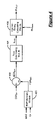
- FIG. 4 is a functional block diagram of exemplary modules that execute the combustion control of the present invention.
- module refers to an application specific integrated circuit (ASIC), an electronic circuit, a processor (shared, dedicated, or group) and memory that execute one or more software or firmware programs, a combinational logic circuit, and/or other suitable components that provide the described functionality.
- ASIC application specific integrated circuit
- processor shared, dedicated, or group
- memory that execute one or more software or firmware programs, a combinational logic circuit, and/or other suitable components that provide the described functionality.
- the engine system 10 includes an engine 12 , an intake manifold 14 , a fuel injection system 16 and an exhaust system 18 .
- Air is drawn into the intake manifold 14 through a throttle 25 and a filter 27 . Air is drawn into the cylinders 20 from the intake manifold 14 and is compressed therein. Fuel is injected by the injection system 16 and the air/fuel mixture is combusted within the cylinders 20 . The exhaust gases are exhausted from the cylinders 20 and into the exhaust system 18 .
- the engine system 10 can include a turbo 26 that pumps additional air into the cylinders 20 . In such a system, the turbo 26 , which is driven by the exhaust gas, compresses the air and the compressed air flows through the throttle 25 .
- the exhaust system 18 includes an exhaust manifold 30 , an exhaust conduit 31 , an EGR valve 34 , an EGR conduit 35 and an EGR cooler 36 .
- the exhaust manifold 30 directs the exhaust from the cylinder banks 22 , 24 into the exhaust conduit 31 .
- the EGR valve 34 selectively re-circulates a portion of the exhaust through the EGR conduit 35 , as explained in further detail below.
- the remainder of the exhaust is directed into the turbo 26 to drive the turbo 26 .
- the exhaust stream flows from the turbo 26 to an exhaust after-treatment system (not illustrated).
- a control module 42 regulates operation of the engine system 10 based on the combustion control of the present invention. More specifically, the control module 42 controls operation of both the fuel injection timing (i.e., the point at which fuel is injected into a cylinder relative to a crank angle and a piston position within the cylinder) and the EGR valve 34 .
- the control module 42 communicates with an intake manifold absolute pressure (MAP) sensor 44 and an engine speed sensor 46 .
- MAP sensor 44 generates a signal indicating the air pressure within the intake manifold 14 and the engine speed sensor 46 generates a signal indicating engine speed (RPM).
- the control module 42 determines an engine load based on the RPM and fueling rates.
- the control module 42 also communicates with a mass airflow (MAF) sensor 47 that generates a MAF signal and an intake manifold temperature sensor 49 that is responsive to the intake manifold air temperature (T IM ).
- MAF mass airflow
- the combustion control of the present invention regulates the EGR valve 34 and the fuel injection timing to minimize emission excursions during transient engine operation.
- transient refers to a transition in engine operation from a first steady-state condition to a second steady-state condition.
- the combustion control adjusts the fuel injection timing based on an EGR error (EGR ERR ).
- EGR ERR is calculated as the difference between an estimated actual EGR rate (EGR EST ) and a set-point EGR rate (EGR SP ).
- EGR EST is estimated based on the difference of MAF and an estimated charge flow (CF). MAF is measured directly using the MAF sensor 47 .
- CF is calculated using a speed-density relationship as a function of T IM , MAP, engine RPM and the volumetric efficiency (V EFF ) of the engine.
- EGR SP is determined based on engine RPM and torque using a pre-determined look-up table stored in memory.
- the combustion control determines a base injection timing (INJ BASE ) from a main injection timing schedule. More specifically, INJ BASE is determined based on engine RPM and torque using a pre-determined look-up table stored in memory. An actual injection timing (INJ ACT ) is determined based on INJ BASE and EGR ERR . More specifically, a timing constant (k TIME ) is determined based on EGR ERR using a pre-determined look-up table stored in memory. k TIME is applied to INJ BASE using dynamics such as filtering. For example, time-variable first order filter can be applied to INJ BASE using k TIME to determine INJ ACT . In this manner, no additional timing calibration is required. Alternatively, INJ ACT can be determined from a pre-determined look-up table based on EGR ERR and INJ BASE , and a filter can be applied to the table output.
- the filter When operating in steady-state, the filter does not affect INJ BASE , whereby INJ ACT is equal to INJ BASE . However, when transient, the filter adjusts INJ BASE to provide INJ ACT . In this manner, the Combustion control of the present invention automatically determines when the engine is operating in transient state.
- Fuel injection timing is a more rapid engine operation actuator as compared to EGR and has sufficient control authority to affect HC and NO x during deviations of EGR EST from EGR SP .
- active and efficient reduction of emissions is enabled using INJ ACT as the control parameter based on EGR ERR .
- the combustion control of the present invention is operable throughout the entire engine operating region and eliminates the need for switching logic between different modes of combustion (e.g., low temperature combustion, diffusion combustion, partial HCCl combustion) by providing seamless transitions therebetween.
- exemplary injection timing (INJ ACT ), NO x and HC traces are illustrated for an exemplary transient engine operation (e.g., acceleration).
- the solid line indicates of traditional combustion control
- the dashed line indicates the combustion control in accordance with the present invention.
- INJ ACT using the combustion control of the present invention is advanced relative to that using traditional combustion control.
- NO x emissions are slightly increased over that produced using the traditional combustion control, however, HC emissions are significantly reduced using the combustion control of the present invention.
- control determines INJ BASE , MAF, CF and EGR SP .
- control calculates EGR EST based on MAF and CF.
- control calculates EGR ERR based on EGR SP and EGR EST in step 304 and determines k TIME based on EGR ERR in step 306 .
- control determines INJ ACT based on INJ BASE and k TIME .
- Control regulates operation of the engine based on INJ ACT in step 310 and control ends.
- the exemplary modules include an EGR estimating module 400 , a summer 402 , a k TIME determining module 404 and an injection timing calculating module 406 .
- the EGR estimating module 400 determines EGR EST based on MAF and CF.
- the summer 402 determines EGR ERR based on EGR SP and EGR EST .
- k TIME is determined by the k TIME determining module 404 based on EGR ERR .
- the injection timing calculating module 406 calculates INJ ACT based on k TIME and INJ BASE .
- the engine 12 is subsequently operated based on INJ ACT .
Landscapes
- Engineering & Computer Science (AREA)
- Chemical & Material Sciences (AREA)
- Combustion & Propulsion (AREA)
- Mechanical Engineering (AREA)
- General Engineering & Computer Science (AREA)
- Output Control And Ontrol Of Special Type Engine (AREA)
- Electrical Control Of Air Or Fuel Supplied To Internal-Combustion Engine (AREA)
- Combined Controls Of Internal Combustion Engines (AREA)
Abstract
Description
Claims (22)
Priority Applications (3)
| Application Number | Priority Date | Filing Date | Title |
|---|---|---|---|
| US11/342,925 US7321820B2 (en) | 2006-01-30 | 2006-01-30 | Model-based inlet air dynamics state characterization |
| DE102007003246.5A DE102007003246B4 (en) | 2006-01-30 | 2007-01-23 | Apparatus and method for controlling AGR-equipped internal combustion engines |
| CN2007100063481A CN101025122B (en) | 2006-01-30 | 2007-01-30 | Device and method for controlling internal-combustion engine capable of waste gas recycle |
Applications Claiming Priority (1)
| Application Number | Priority Date | Filing Date | Title |
|---|---|---|---|
| US11/342,925 US7321820B2 (en) | 2006-01-30 | 2006-01-30 | Model-based inlet air dynamics state characterization |
Publications (2)
| Publication Number | Publication Date |
|---|---|
| US20070175452A1 US20070175452A1 (en) | 2007-08-02 |
| US7321820B2 true US7321820B2 (en) | 2008-01-22 |
Family
ID=38282386
Family Applications (1)
| Application Number | Title | Priority Date | Filing Date |
|---|---|---|---|
| US11/342,925 Expired - Lifetime US7321820B2 (en) | 2006-01-30 | 2006-01-30 | Model-based inlet air dynamics state characterization |
Country Status (3)
| Country | Link |
|---|---|
| US (1) | US7321820B2 (en) |
| CN (1) | CN101025122B (en) |
| DE (1) | DE102007003246B4 (en) |
Cited By (4)
| Publication number | Priority date | Publication date | Assignee | Title |
|---|---|---|---|---|
| US20090018752A1 (en) * | 2005-04-28 | 2009-01-15 | Renault S.A.S | Method for controlling a motor vehicle using a network of neurones |
| US20090192699A1 (en) * | 2008-01-29 | 2009-07-30 | Honda Motor Co., Ltd. | Control system for internal combustion engine |
| US20110023845A1 (en) * | 2009-07-31 | 2011-02-03 | Detroit Diesel Corporation | Method of diagnosing a slow egr system in an internal combustion engine |
| US20130319377A1 (en) * | 2012-06-05 | 2013-12-05 | Hondata, Inc. | Engine control unit using speed density conversion |
Families Citing this family (5)
| Publication number | Priority date | Publication date | Assignee | Title |
|---|---|---|---|---|
| DE102011004190B4 (en) * | 2011-02-16 | 2023-10-05 | Bayerische Motoren Werke Aktiengesellschaft | Method for specifying injection pulses |
| US9222426B2 (en) * | 2012-02-17 | 2015-12-29 | Ford Global Technologies, Llc | Transient air flow control |
| US20130319381A1 (en) * | 2012-05-30 | 2013-12-05 | GM Global Technology Operations LLC | Engine including venturi in intake air flow path for exhaust gas recirculation supply |
| US9175624B2 (en) * | 2012-12-18 | 2015-11-03 | Fca Us Llc | Exhaust gas recirculation control method and system |
| JP6848812B2 (en) * | 2017-10-25 | 2021-03-24 | トヨタ自動車株式会社 | Internal combustion engine control device |
Citations (11)
| Publication number | Priority date | Publication date | Assignee | Title |
|---|---|---|---|---|
| US4432331A (en) * | 1981-06-30 | 1984-02-21 | Nissan Motor Company, Limited | Engine control system |
| US5241937A (en) * | 1991-12-09 | 1993-09-07 | Honda Giken Kogyo Kabushiki Kaisha | Misfire-detecting system for internal combustion engines |
| JPH09280117A (en) * | 1996-04-09 | 1997-10-28 | Nissan Motor Co Ltd | Diesel engine controller |
| US5682864A (en) * | 1995-08-01 | 1997-11-04 | Nissan Motor Co., Ltd. | Controller for internal combustion engines |
| US5950604A (en) * | 1996-11-29 | 1999-09-14 | Nissan Motor Co., Ltd | Engine, engine manufacturing method and engine heat |
| US5964820A (en) * | 1996-11-13 | 1999-10-12 | Nissan Motor Co., Ltd. | Diesel engine exhaust recirculating system diagnostic |
| US6012431A (en) * | 1996-06-03 | 2000-01-11 | Nissan Motor Co., Ltd. | Control apparatus for internal combustion engine and estimation apparatus for estimating pressure in intake and discharge system of internal combustion engine |
| JP2002309972A (en) * | 2001-04-11 | 2002-10-23 | Toyota Motor Corp | Control device for internal combustion engine |
| US6659091B2 (en) * | 2000-08-22 | 2003-12-09 | Robert Bosch Gmbh | Method for compensating for abnormal changes in the gas flow passing through an exhaust gas recirculation line of an internal combustion engine |
| US7163007B2 (en) * | 2004-07-14 | 2007-01-16 | Honda Motor Co., Ltd. | Control system for internal combustion engine |
| US20070073467A1 (en) * | 2003-09-23 | 2007-03-29 | Westport Research Inc. | Method for controlling combustion in an internal combustion engine and predicting performance and emissions |
Family Cites Families (3)
| Publication number | Priority date | Publication date | Assignee | Title |
|---|---|---|---|---|
| KR100462458B1 (en) * | 1996-03-15 | 2005-05-24 | 지멘스 악티엔게젤샤프트 | How to use the model to determine the mass of clean air flowing into the cylinder of an internal combustion engine that recycles external exhaust gas |
| DE19727866C2 (en) * | 1997-06-30 | 2003-03-20 | Siemens Ag | Device for controlling an internal combustion engine |
| DE10321192A1 (en) * | 2003-05-12 | 2004-12-02 | Volkswagen Ag | Controlling internal combustion engine, especially a diesel, involves assessing dynamic operating condition of engine and adjusting fuel supply or injection starting point depending on working point |
-
2006
- 2006-01-30 US US11/342,925 patent/US7321820B2/en not_active Expired - Lifetime
-
2007
- 2007-01-23 DE DE102007003246.5A patent/DE102007003246B4/en active Active
- 2007-01-30 CN CN2007100063481A patent/CN101025122B/en active Active
Patent Citations (13)
| Publication number | Priority date | Publication date | Assignee | Title |
|---|---|---|---|---|
| US4432331A (en) * | 1981-06-30 | 1984-02-21 | Nissan Motor Company, Limited | Engine control system |
| US5241937A (en) * | 1991-12-09 | 1993-09-07 | Honda Giken Kogyo Kabushiki Kaisha | Misfire-detecting system for internal combustion engines |
| US5682864A (en) * | 1995-08-01 | 1997-11-04 | Nissan Motor Co., Ltd. | Controller for internal combustion engines |
| JPH09280117A (en) * | 1996-04-09 | 1997-10-28 | Nissan Motor Co Ltd | Diesel engine controller |
| US6012431A (en) * | 1996-06-03 | 2000-01-11 | Nissan Motor Co., Ltd. | Control apparatus for internal combustion engine and estimation apparatus for estimating pressure in intake and discharge system of internal combustion engine |
| US6167342A (en) * | 1996-06-03 | 2000-12-26 | Nissan Motor Co., Ltd. | Control apparatus for internal combustion engine and estimation apparatus for estimating pressure in intake and discharge system of internal combustion engine |
| US6298299B1 (en) * | 1996-06-03 | 2001-10-02 | Nissan Motor Co., Ltd. | Control apparatus for internal combustion engine and estimation apparatus for estimating pressure in intake and discharge system of internal combustion engine |
| US5964820A (en) * | 1996-11-13 | 1999-10-12 | Nissan Motor Co., Ltd. | Diesel engine exhaust recirculating system diagnostic |
| US5950604A (en) * | 1996-11-29 | 1999-09-14 | Nissan Motor Co., Ltd | Engine, engine manufacturing method and engine heat |
| US6659091B2 (en) * | 2000-08-22 | 2003-12-09 | Robert Bosch Gmbh | Method for compensating for abnormal changes in the gas flow passing through an exhaust gas recirculation line of an internal combustion engine |
| JP2002309972A (en) * | 2001-04-11 | 2002-10-23 | Toyota Motor Corp | Control device for internal combustion engine |
| US20070073467A1 (en) * | 2003-09-23 | 2007-03-29 | Westport Research Inc. | Method for controlling combustion in an internal combustion engine and predicting performance and emissions |
| US7163007B2 (en) * | 2004-07-14 | 2007-01-16 | Honda Motor Co., Ltd. | Control system for internal combustion engine |
Cited By (8)
| Publication number | Priority date | Publication date | Assignee | Title |
|---|---|---|---|---|
| US20090018752A1 (en) * | 2005-04-28 | 2009-01-15 | Renault S.A.S | Method for controlling a motor vehicle using a network of neurones |
| US7774127B2 (en) * | 2005-04-28 | 2010-08-10 | Renault S.A.S. | Method for controlling a motor vehicle using a network of neurones |
| US20090192699A1 (en) * | 2008-01-29 | 2009-07-30 | Honda Motor Co., Ltd. | Control system for internal combustion engine |
| US7792631B2 (en) * | 2008-01-29 | 2010-09-07 | Honda Motor Co., Ltd. | Control system for internal combustion engine |
| US20110023845A1 (en) * | 2009-07-31 | 2011-02-03 | Detroit Diesel Corporation | Method of diagnosing a slow egr system in an internal combustion engine |
| US8109258B2 (en) * | 2009-07-31 | 2012-02-07 | Detroit Diesel Corporation | Method of diagnosing a slow EGR system in an internal combustion engine |
| US20130319377A1 (en) * | 2012-06-05 | 2013-12-05 | Hondata, Inc. | Engine control unit using speed density conversion |
| US9091224B2 (en) * | 2012-06-05 | 2015-07-28 | Hondata, Inc. | Engine control unit using speed density conversion |
Also Published As
| Publication number | Publication date |
|---|---|
| US20070175452A1 (en) | 2007-08-02 |
| DE102007003246A1 (en) | 2007-08-09 |
| CN101025122A (en) | 2007-08-29 |
| CN101025122B (en) | 2011-07-27 |
| DE102007003246B4 (en) | 2017-04-27 |
Similar Documents
| Publication | Publication Date | Title |
|---|---|---|
| US7440838B2 (en) | Torque based air per cylinder and volumetric efficiency determination | |
| US7021282B1 (en) | Coordinated engine torque control | |
| US7463970B2 (en) | Torque based engine speed control | |
| US7395147B2 (en) | Torque control of turbocharged engine | |
| US7433775B2 (en) | Engine torque control at high pressure ratio | |
| US7150264B2 (en) | Control device for internal combustion engine | |
| US7533658B2 (en) | Coordinated control of throttle and EGR valve | |
| CN101025122B (en) | Device and method for controlling internal-combustion engine capable of waste gas recycle | |
| JP5187123B2 (en) | Control device for internal combustion engine | |
| JP6093258B2 (en) | Failure detection device for exhaust gas recirculation device of supercharged engine | |
| US7742866B2 (en) | Fuel volatility compensation for engine cold start speed control | |
| US20130133634A1 (en) | Controller for internal combustion engine | |
| US7493896B2 (en) | Exhaust gas recirculation estimation system | |
| JP2014202137A (en) | Exhaust gas recirculation device of engine | |
| US7769526B2 (en) | Diesel transient combustion control based on intake carbon dioxide concentration | |
| JP4415509B2 (en) | Control device for internal combustion engine | |
| JP4561816B2 (en) | Abnormality determination device and abnormality determination method for internal combustion engine | |
| US6895946B1 (en) | Torque control of supercharged engine | |
| JP6458480B2 (en) | Exhaust gas recirculation control device | |
| US10526986B2 (en) | Systems and methods for controlling EGR flow rate | |
| US7606653B2 (en) | Vehicle speed dependant calibration trim for improved fuel economy | |
| JP2013148067A (en) | Control device of internal combustion engine | |
| JP6234810B2 (en) | Engine control device | |
| US7991540B2 (en) | Vehicle speed dependant calibration trim or user-selectable calbratable trim for improved fuel economy | |
| JP2007303380A (en) | Exhaust control device for internal combustion engine |
Legal Events
| Date | Code | Title | Description |
|---|---|---|---|
| AS | Assignment |
Owner name: GM GLOBAL TECHNOLOGY OPERATIONS, INC., MICHIGAN Free format text: ASSIGNMENT OF ASSIGNORS INTEREST;ASSIGNORS:YANAKIEV, OGNYAN N.;LIN, CHAN-CHIAO;TAHRY, SHERIF H. EL;REEL/FRAME:017499/0868 Effective date: 20060324 |
|
| STCF | Information on status: patent grant |
Free format text: PATENTED CASE |
|
| AS | Assignment |
Owner name: UNITED STATES DEPARTMENT OF THE TREASURY, DISTRICT Free format text: SECURITY AGREEMENT;ASSIGNOR:GM GLOBAL TECHNOLOGY OPERATIONS, INC.;REEL/FRAME:022201/0363 Effective date: 20081231 Owner name: UNITED STATES DEPARTMENT OF THE TREASURY,DISTRICT Free format text: SECURITY AGREEMENT;ASSIGNOR:GM GLOBAL TECHNOLOGY OPERATIONS, INC.;REEL/FRAME:022201/0363 Effective date: 20081231 |
|
| AS | Assignment |
Owner name: CITICORP USA, INC. AS AGENT FOR BANK PRIORITY SECU Free format text: SECURITY AGREEMENT;ASSIGNOR:GM GLOBAL TECHNOLOGY OPERATIONS, INC.;REEL/FRAME:022553/0493 Effective date: 20090409 Owner name: CITICORP USA, INC. AS AGENT FOR HEDGE PRIORITY SEC Free format text: SECURITY AGREEMENT;ASSIGNOR:GM GLOBAL TECHNOLOGY OPERATIONS, INC.;REEL/FRAME:022553/0493 Effective date: 20090409 |
|
| AS | Assignment |
Owner name: GM GLOBAL TECHNOLOGY OPERATIONS, INC., MICHIGAN Free format text: RELEASE BY SECURED PARTY;ASSIGNOR:UNITED STATES DEPARTMENT OF THE TREASURY;REEL/FRAME:023124/0519 Effective date: 20090709 Owner name: GM GLOBAL TECHNOLOGY OPERATIONS, INC.,MICHIGAN Free format text: RELEASE BY SECURED PARTY;ASSIGNOR:UNITED STATES DEPARTMENT OF THE TREASURY;REEL/FRAME:023124/0519 Effective date: 20090709 |
|
| AS | Assignment |
Owner name: GM GLOBAL TECHNOLOGY OPERATIONS, INC., MICHIGAN Free format text: RELEASE BY SECURED PARTY;ASSIGNORS:CITICORP USA, INC. AS AGENT FOR BANK PRIORITY SECURED PARTIES;CITICORP USA, INC. AS AGENT FOR HEDGE PRIORITY SECURED PARTIES;REEL/FRAME:023127/0402 Effective date: 20090814 Owner name: GM GLOBAL TECHNOLOGY OPERATIONS, INC.,MICHIGAN Free format text: RELEASE BY SECURED PARTY;ASSIGNORS:CITICORP USA, INC. AS AGENT FOR BANK PRIORITY SECURED PARTIES;CITICORP USA, INC. AS AGENT FOR HEDGE PRIORITY SECURED PARTIES;REEL/FRAME:023127/0402 Effective date: 20090814 |
|
| AS | Assignment |
Owner name: UNITED STATES DEPARTMENT OF THE TREASURY, DISTRICT Free format text: SECURITY AGREEMENT;ASSIGNOR:GM GLOBAL TECHNOLOGY OPERATIONS, INC.;REEL/FRAME:023156/0142 Effective date: 20090710 Owner name: UNITED STATES DEPARTMENT OF THE TREASURY,DISTRICT Free format text: SECURITY AGREEMENT;ASSIGNOR:GM GLOBAL TECHNOLOGY OPERATIONS, INC.;REEL/FRAME:023156/0142 Effective date: 20090710 |
|
| AS | Assignment |
Owner name: UAW RETIREE MEDICAL BENEFITS TRUST, MICHIGAN Free format text: SECURITY AGREEMENT;ASSIGNOR:GM GLOBAL TECHNOLOGY OPERATIONS, INC.;REEL/FRAME:023162/0093 Effective date: 20090710 Owner name: UAW RETIREE MEDICAL BENEFITS TRUST,MICHIGAN Free format text: SECURITY AGREEMENT;ASSIGNOR:GM GLOBAL TECHNOLOGY OPERATIONS, INC.;REEL/FRAME:023162/0093 Effective date: 20090710 |
|
| AS | Assignment |
Owner name: GM GLOBAL TECHNOLOGY OPERATIONS, INC., MICHIGAN Free format text: RELEASE BY SECURED PARTY;ASSIGNOR:UNITED STATES DEPARTMENT OF THE TREASURY;REEL/FRAME:025245/0587 Effective date: 20100420 |
|
| AS | Assignment |
Owner name: GM GLOBAL TECHNOLOGY OPERATIONS, INC., MICHIGAN Free format text: RELEASE BY SECURED PARTY;ASSIGNOR:UAW RETIREE MEDICAL BENEFITS TRUST;REEL/FRAME:025314/0901 Effective date: 20101026 |
|
| AS | Assignment |
Owner name: WILMINGTON TRUST COMPANY, DELAWARE Free format text: SECURITY AGREEMENT;ASSIGNOR:GM GLOBAL TECHNOLOGY OPERATIONS, INC.;REEL/FRAME:025327/0041 Effective date: 20101027 |
|
| AS | Assignment |
Owner name: GM GLOBAL TECHNOLOGY OPERATIONS LLC, MICHIGAN Free format text: CHANGE OF NAME;ASSIGNOR:GM GLOBAL TECHNOLOGY OPERATIONS, INC.;REEL/FRAME:025781/0001 Effective date: 20101202 |
|
| FPAY | Fee payment |
Year of fee payment: 4 |
|
| AS | Assignment |
Owner name: GM GLOBAL TECHNOLOGY OPERATIONS LLC, MICHIGAN Free format text: RELEASE BY SECURED PARTY;ASSIGNOR:WILMINGTON TRUST COMPANY;REEL/FRAME:034184/0001 Effective date: 20141017 |
|
| FPAY | Fee payment |
Year of fee payment: 8 |
|
| MAFP | Maintenance fee payment |
Free format text: PAYMENT OF MAINTENANCE FEE, 12TH YEAR, LARGE ENTITY (ORIGINAL EVENT CODE: M1553); ENTITY STATUS OF PATENT OWNER: LARGE ENTITY Year of fee payment: 12 |