US7315954B2 - Hardware switching apparatus for soft power-down and remote power-up - Google Patents
Hardware switching apparatus for soft power-down and remote power-up Download PDFInfo
- Publication number
- US7315954B2 US7315954B2 US10/394,355 US39435503A US7315954B2 US 7315954 B2 US7315954 B2 US 7315954B2 US 39435503 A US39435503 A US 39435503A US 7315954 B2 US7315954 B2 US 7315954B2
- Authority
- US
- United States
- Prior art keywords
- power
- switching
- switching device
- switch
- computer system
- Prior art date
- Legal status (The legal status is an assumption and is not a legal conclusion. Google has not performed a legal analysis and makes no representation as to the accuracy of the status listed.)
- Expired - Fee Related, expires
Links
- 230000004044 response Effects 0.000 claims description 18
- 238000000034 method Methods 0.000 claims description 8
- 230000002093 peripheral effect Effects 0.000 claims description 7
- 230000011664 signaling Effects 0.000 claims description 4
- 229910000859 α-Fe Inorganic materials 0.000 claims description 3
- 230000000977 initiatory effect Effects 0.000 abstract description 4
- 238000012544 monitoring process Methods 0.000 description 7
- 238000010586 diagram Methods 0.000 description 4
- 230000006870 function Effects 0.000 description 4
- 230000008901 benefit Effects 0.000 description 3
- 230000014509 gene expression Effects 0.000 description 2
- 238000012549 training Methods 0.000 description 2
- 238000006243 chemical reaction Methods 0.000 description 1
- 238000003745 diagnosis Methods 0.000 description 1
- 238000012360 testing method Methods 0.000 description 1
Images


Classifications
-
- G—PHYSICS
- G06—COMPUTING; CALCULATING OR COUNTING
- G06F—ELECTRIC DIGITAL DATA PROCESSING
- G06F1/00—Details not covered by groups G06F3/00 - G06F13/00 and G06F21/00
- G06F1/26—Power supply means, e.g. regulation thereof
- G06F1/30—Means for acting in the event of power-supply failure or interruption, e.g. power-supply fluctuations
-
- G—PHYSICS
- G06—COMPUTING; CALCULATING OR COUNTING
- G06F—ELECTRIC DIGITAL DATA PROCESSING
- G06F1/00—Details not covered by groups G06F3/00 - G06F13/00 and G06F21/00
- G06F1/26—Power supply means, e.g. regulation thereof
- G06F1/32—Means for saving power
- G06F1/3203—Power management, i.e. event-based initiation of a power-saving mode
- G06F1/3206—Monitoring of events, devices or parameters that trigger a change in power modality
- G06F1/3209—Monitoring remote activity, e.g. over telephone lines or network connections
-
- G—PHYSICS
- G06—COMPUTING; CALCULATING OR COUNTING
- G06F—ELECTRIC DIGITAL DATA PROCESSING
- G06F11/00—Error detection; Error correction; Monitoring
- G06F11/07—Responding to the occurrence of a fault, e.g. fault tolerance
- G06F11/14—Error detection or correction of the data by redundancy in operation
- G06F11/1402—Saving, restoring, recovering or retrying
- G06F11/1415—Saving, restoring, recovering or retrying at system level
- G06F11/1441—Resetting or repowering
Definitions
- the present invention relates to a hardware switching apparatus for controlling a computer system, and particularly to a hardware switching apparatus for initiating a soft power-down and a remote power-up in a computer system that has as its power supply an uninterruptible power supply.
- Soft power-down Any data that may be stored in a volatile memory can be corrupted or lost if the power supplied to a computer is abruptly terminated (a “hard power-down”).
- the soft power-down feature prevents data stored in a non-volatile memory from being lost or corrupted by closing programs and files in an orderly manner, and terminating the power supplied to the computer system's circuits only after all of the data has been saved.
- the soft power-down feature is commonly invoked by issuing a command to the operating system. For example, the soft power-down command can be issued by selecting a “Turn Off Computer” option from a menu. Depending on the particular computer system, the soft power-down usually takes a minute or two to complete.
- UPS uninterruptible power supply
- the UPS is connected in series between a primary power source, such as a wall outlet, and the computer system.
- the UPS includes circuitry for monitoring the primary power source.
- the UPS immediately switches the load to a backup power source when it senses that the primary power source has failed.
- the backup power source is a battery that is capable of supplying power to the load for a limited period of time.
- a UPS generally includes a microprocessor or a logic circuit that causes the UPS to send a power-down signal to notify the operating system that the UPS is furnishing power from the backup power source.
- the computer system In response to the power-down signal, the computer system causes the operating system to execute a soft power-down. After a predetermined time period (that is longer than the maximum time required for the operating system to complete the soft power-down), the UPS stops furnishing power from the backup power source.
- the UPS typically supplies power for about 3 minutes after switching to the backup power source.
- UPS Control Software Power monitoring and protection software
- UPS Control Software is available to work with a UPS.
- UPS Control Software program marketed as POWERCHUTE PLUS is available from American Power Conversion Corporation, West Kingston, R.I. and is apparently intended for use by a system administrator managing a number of distributed computer systems.
- An administrative computer running the UPS Control Software is coupled to the UPS.
- the UPS Control Software may include notification of impending shut down, power event logging, auto-restart upon power return, and battery conservation features.
- the UPS Control Software may provide automatic battery testing, power problem diagnosis, and may support the remote scheduling of shut downs and re-boots. Problems with the UPS Control Software include that the software provides many more functions than are needed for a simple application and that a second computer system is required to run the software.
- the use of the UPS Control Software to control a UPS may be unnecessarily complicated and expensive, especially if all that is needed is a means to prevent a hard power-down.
- a user interface that hides the operating system from the user is often employed in special purpose computer systems as opposed to general purpose computer systems, such as a personal computer.
- a special purpose computer system that is designed to perform a single function or a limited set of functions will generally have software running on it that provides a simplified user interface.
- One example of a special purpose computer system is a portrait printing system.
- the portrait printing system employs a simplified user interface that permits editing and printing of images, but hides the operating system from the user.
- a problem with some special purpose computer systems is that the user interface does not provide for a soft power-down.
- Another problem with some special purpose computer systems is that the system may be enclosed in a cabinet making the computer's on/off switch inaccessible so that there may be no convenient way to power-up the system.
- This invention is a hardware switching apparatus for initiating a soft power-down and a remote power-up in a computer system that preferably has an impending power failure port for receiving a power-down signal for signaling the computer system to perform a soft power-down, a start port for receiving a start-up signal for signaling the computer system to power-up, and has as its power supply a UPS.
- the UPS is adapted to (a) receive power from a primary power source, (b) sense the power delivered from the primary source, (c) produce a power-down signal in response to an interruption in the power from the primary source, and (d) provide the power-down signal to the impending power failure port of the computer system.
- the hardware switching apparatus includes a switching device having a first switch position and a switching circuit coupled to the switching device and said power supply.
- the switching circuit is adapted to cause the power supply to produce a power-down signal when the switching device is in the first switch position.
- the switching circuit is adapted to cause a power switch having a primary power source position and a backup power source position to switch to the backup source position when the switching device is in the first switch position.
- the hardware switching apparatus also includes a wiring harness for remotely controlling the switching circuit. The wiring harness is separate from the switching device and the switching circuit.
- the switching device has a second switch position and the switching circuit is adapted to cause the power supply to produce a start-up signal when the switching device is in the second switch position.
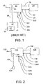
- FIG. 1 is a block diagram of a prior art system for monitoring and controlling a UPS for supplying power to a computer system, including a UPS and an administrative computer running UPS control software.
- FIG. 2 is a block diagram of a hardware switching apparatus for soft power-down and remote power-up according to the present invention, including a UPS for supplying power to a computer system, a switching circuit, a switch harness, and a switching device.
- FIG. 3 is a block diagram of the switching circuit, the switch harness, and the switching device shown in FIG. 2 .
- FIG. 4 is a schematic of the switch harness shown in FIG. 3 .
- FIG. 5 is a diagram showing a cut-away side view of an exemplary enclosure for a special purpose computer system.
- the UPS 22 typically has a relay I/O (input/output) card 26 that couples the UPS to optional devices.
- the UPS 22 has a power input 28 and power outputs 30 a , 30 b , 30 c , and 30 d .
- the power input 28 is coupled to a primary power source, such as a wall outlet.
- the UPS 22 supplies power from the power output 30 d to a power input 32 of the computer system 24 through a power cable 34 .
- the power outputs 30 a , 30 b , and 30 c optionally supply power to peripheral devices or other computer systems.
- a first communications cable 36 is used to transmit signals between the UPS 22 and the computer system 24 .
- a second communications cable 38 is used to transmit signals between the UPS 22 and the control and monitoring system 20 .
- the control and monitoring system 20 includes a computer system 40 and UPS control software 42 .
- FIG. 2 shows a UPS 122 that supplies power to a special purpose computer system 124 .
- the UPS 122 preferably has a switching circuit 126 that couples the UPS 122 to a switching device 128 via a switch harness 130 .
- the exemplary hardware switching apparatus preferably includes the switching circuit 126 , the switching device 128 , and the switch harness 130 .
- the switching circuit 126 and the UPS 122 are coupled by signals which are transmitted wirelessly (that is, sonically, optically, or by radio broadcast) and the switching apparatus includes one or more transmitters and receivers, as appropriate or desired.
- the UPS 122 has a power input line 132 and power outputs 134 a , 134 b , 134 c , and 134 d .
- the power input 132 is coupled to a primary power source, such as a wall outlet.
- the UPS 122 supplies power from the power output 134 d to a power input 136 on the special purpose computer system 124 through a power cable 138 .
- the power outputs 134 a , 134 b , and 134 c optionally supply power to peripheral devices or other computer systems.
- a communications cable 140 is used to transmit signals between the UPS 122 and the special purpose computer system 124 .
- a primary power source 142 the special purpose computer system 124 , and the UPS 122 are shown.
- the UPS 122 is coupled to both the computer system 124 and the primary power source 142 .
- the UPS 122 is also coupled to a backup power source 144 , which may be an internal component of the UPS, as shown.
- the UPS 122 includes a power switch 146 which is coupled to the primary and backup power sources 142 , 144 .
- the power switch 146 is also coupled to the computer system 124 .
- the switching device 128 , the switch harness 130 , and the switching circuit 126 are also shown in FIG. 3 .
- the switching circuit 126 is shown as an internal component of the UPS 122 , though it need not be part of the UPS itself.
- the switching circuit 126 is coupled to the switching device 128 through the switch harness 130 and a connector 148 .
- the switching circuit 126 is also coupled to a power monitor 150 , the power switch 146 , and the computer system 124 .
- the power monitor 150 is for monitoring the power supplied on an input power line 132 .
- the switching circuit 126 includes UPS control logic 152 , an OR gate 154 , a signal power source 156 , and a timer 158 .
- the UPS control logic 152 is coupled to the power switch 146 through signal line 160 and to the computer system 124 .
- the computer system 124 has an impending power failure port 162 and a start port 164 .
- the UPS control logic 152 is directly coupled to these ports through the communications cable 140 in one embodiment.
- the UPS control logic 152 may alternatively be coupled to one or more components of the UPS that, in turn, are coupled to these ports.
- the UPS control logic 152 is coupled to the timer 158 .
- the UPS control logic 152 is coupled to the switching device 128 by signal line 170 and to the output of the OR gate 154 by signal line 172 .
- the OR gate 152 has for one of its inputs a signal line 174 coupled to the power monitor 150 and for its other input the signal line 168 , which is coupled to switching device 128 .
- the switching device 128 is also coupled to the signal power source 156 .
- the power monitor 150 When the power monitor 150 detects that power is no longer flowing at an appropriate level in the power line 132 , it sends a “power fail” signal through the OR gate 154 to the UPS control logic 152 .
- the power fail signal causes the control logic 154 to send a control signal to the power switch 146 causing the power switch to move to the 176 a position, a position at which power is supplied to the special purpose computer system 124 from the backup power source 144 .
- the power fail signal causes the control logic 152 to send a power-down signal to the impending power failure port 162 of the special purpose computer system 124 . Asserting a power-down signal on the impending power failure port 162 causes the operating system to initiate a soft power-down.
- the power-down signal also causes the control logic 152 to start the timer 158 .
- the timer 158 counts off a predetermined time period and sends a timer signal to the control logic 152 at the end of the period.
- the control logic 152 preferably generates a control signal that causes the power switch 146 to move to switch position 176 b .
- Neither the primary power source 142 nor the backup power source 144 is coupled to the special purpose computer system 124 when the power switch 146 is set to power switch position 176 b .
- the control logic 152 at the end of the predetermined time period, the control logic 152 generates a control signal that causes the power switch 146 to move to switch position 176 c , a position at which the primary power source 142 can supply power to the special purpose computer system 124 .
- the switching device 128 is moved to the 178 a position, a position which causes the switching circuit 126 to send a power-fail signal through the OR gate 154 to the control logic 152 . It may be sufficient to momentarily move the switching device 128 to the 178 a position, or it may be necessary to move the switching device 128 so that it permanently remains in the 178 a position.
- the power fail signal causes the control logic 152 to send a power-down signal to the impending power failure port 162 of the computer system 124 .
- the UPS control logic 152 sends a signal to a component of the UPS that, in turn, sends the power fail signal to the impending power failure port 162 .
- this causes the system 124 to initiate a soft power-down.
- the UPS 122 stops supplying power from the backup power source 144 in the same manner as that described above for a soft power-down caused by a power supply interruption.
- the switching device 128 is moved to the 178 b position which causes the switching circuit 126 to send a start signal to the control logic 152 . It may be sufficient to momentarily move the switching device 128 to the 178 b position, or it may be necessary to move the switching device 128 so that it remains permanently in the 178 b position.
- the control logic 152 sends a control signal to the power switch 146 that preferably causes it to move to position 176 c , a position at which power from the primary power source 142 is supplied to the special purpose computer system 124 .
- the special purpose computer system 124 preferably initiates a power-up when it receives power on the power cable 138 .
- the placing of the switching device 128 in the 178 b position causes the switching circuit 126 to send a start signal to the control logic 152 .
- the start signal causes the control logic 152 to send a start-up signal to the start port 164 of the computer system 124 . This causes the computer system 124 to initiate a power-up.
- the UPS control logic 152 sends a signal to a component of the UPS that, in turn, sends a start-up signal to the start port 164 .
- the control logic 152 sends a control signal to the power switch 146 that causes it to select switch position 176 c , a position at which power is supplied to the special purpose computer system 124 from the primary power source 142 .
- the switch harness 130 has three wires 180 a , 180 b , 180 c that are coupled at one end to the switching device 128 and at an opposite end through the connector 148 to the switching circuit 126 .
- the switch harness 130 has a conductive shield that encloses the three wires 180 a , 180 b , 180 c in order to reduce electromagnetic interference.
- the switch harness 130 includes a ferrite core for reducing electromagnetic interference. The ferrite core surrounds one section of the three wires 180 a , 180 b , 180 c.
- the soft power-down and the remote power-up disclosed here are preferably made remotely, but may be made non-remotely.
- the degree of remoteness is established by the length of switch harness 130 .
- the length of the switch harness 130 is about two feet, though it may be longer or shorter.
- FIG. 5 a cut-away side view of an exemplary enclosure 182 for holding a special purpose computer system is shown.
- the special purpose computer system 124 , the UPS 122 , and a peripheral device 184 are contained within the enclosure 182 .
- An access door 186 provides convenient access to the peripheral device 184 .
- the switching device 128 is accessible on a side of the enclosure 182 opposite the door 186 .
- the switching device 128 is connected to the switching circuit 126 by switch harness 130 .
- the power-down and start-up signals are sent to the computer system 124 through communications cable 140 .
- the computer system 124 is supplied power by power cable 138 .
- the computer system 124 communicates with peripheral device 184 through cable 190 .
- the peripheral device 184 receives power from the UPS 124 on a second power cable 192 .
- the communications cable 140 is configured as a 9 pin serial port cable, having busy, standby, rxd, txd, power, ground, and other lines.
- the communications cable 140 is a Universal Serial Bus (“USB”) cable.
- the communications cable 140 is a parallel port cable.
- the switching device 128 is preferably located on the back of the special purpose computer system enclosure 182 . However, the switching device 128 may be placed in any desired location.
- the switching device 128 disclosed herein is preferably a single switch, such as the SPDT SWITCH NKK JWL 12BAA-A single pole double pole throw switch. However, it is contemplated that two switches may be employed instead of a single switch.
- the hardware switching apparatus for a soft power-down and remote power-up disclosed here provides for softly powering-down a special purpose computer system running user interface software that does not provide a soft power-down feature.
- the hardware switching apparatus also provides for remotely powering-up a special purpose computer in which the computer's on-switch is inaccessible.
- the hardware switching apparatus only provides for softly powering-down a special purpose computer system running user interface software that does not provide a soft power-down feature.
- the hardware switching apparatus only provides for remotely powering-up a special purpose computer in which the on-switch is inaccessible.
- the present invention has been described for use with a special purpose computer system, it may be used with any computer system or device in which the soft power-down and remote power-up features provide a benefit. Specifically, the present invention may advantageously be employed with a general purpose computer system.
- the switching circuit 126 has been described as sending power fail and start signals to the UPS control logic 152 , other configurations are contemplated.
- the switching circuit 126 may be adapted to interface to the power monitor 150 , controlling it so as to cause it to send a power fail signal to the control logic 152 .
- the switching circuit 126 may be adapted to control the power supplied on power line 132 . By cutting off power on the power line 132 , the switching circuit 126 will cause the UPS 122 to send a power-down signal to the special purpose computer system 124 thereby remotely causing a soft power-down.
Abstract
Description
Claims (27)
Priority Applications (1)
| Application Number | Priority Date | Filing Date | Title |
|---|---|---|---|
| US10/394,355 US7315954B2 (en) | 2002-08-02 | 2003-03-21 | Hardware switching apparatus for soft power-down and remote power-up |
Applications Claiming Priority (2)
| Application Number | Priority Date | Filing Date | Title |
|---|---|---|---|
| US40062102P | 2002-08-02 | 2002-08-02 | |
| US10/394,355 US7315954B2 (en) | 2002-08-02 | 2003-03-21 | Hardware switching apparatus for soft power-down and remote power-up |
Publications (2)
| Publication Number | Publication Date |
|---|---|
| US20040022184A1 US20040022184A1 (en) | 2004-02-05 |
| US7315954B2 true US7315954B2 (en) | 2008-01-01 |
Family
ID=31191172
Family Applications (1)
| Application Number | Title | Priority Date | Filing Date |
|---|---|---|---|
| US10/394,355 Expired - Fee Related US7315954B2 (en) | 2002-08-02 | 2003-03-21 | Hardware switching apparatus for soft power-down and remote power-up |
Country Status (1)
| Country | Link |
|---|---|
| US (1) | US7315954B2 (en) |
Cited By (5)
| Publication number | Priority date | Publication date | Assignee | Title |
|---|---|---|---|---|
| US8552700B2 (en) | 2010-10-06 | 2013-10-08 | Freescale Semiconductor, Inc. | Switched mode voltage regulator and method of operation |
| US20160154591A1 (en) * | 2010-10-10 | 2016-06-02 | Liqid Inc. | Systems and methods for optimizing data storage among a plurality of storage drives |
| US10114784B2 (en) | 2014-04-25 | 2018-10-30 | Liqid Inc. | Statistical power handling in a scalable storage system |
| CN110521168A (en) * | 2017-04-24 | 2019-11-29 | 昕诺飞控股有限公司 | Power management apparatus for starting immediately during electric power is negotiated |
| US10496504B2 (en) | 2014-06-23 | 2019-12-03 | Liqid Inc. | Failover handling in modular switched fabric for data storage systems |
Families Citing this family (5)
| Publication number | Priority date | Publication date | Assignee | Title |
|---|---|---|---|---|
| US8042004B2 (en) * | 2008-02-25 | 2011-10-18 | International Business Machines Corporation | Diagnosing communications between computer systems |
| US7831710B2 (en) * | 2008-02-25 | 2010-11-09 | International Business Machines Corporation | Communication of offline status between computer systems |
| JP5598118B2 (en) * | 2010-06-28 | 2014-10-01 | 株式会社リコー | Electronic apparatus and image forming apparatus |
| GB2493554A (en) * | 2011-08-11 | 2013-02-13 | Jaybox Ltd | The safe shutdown of digitally controlled entertainment equipment using a secondary power source. |
| CN105676680A (en) * | 2015-12-30 | 2016-06-15 | 联想(北京)有限公司 | Control method and electronic equipment |
Citations (5)
| Publication number | Priority date | Publication date | Assignee | Title |
|---|---|---|---|---|
| US5923099A (en) * | 1997-09-30 | 1999-07-13 | Lam Research Corporation | Intelligent backup power controller |
| US5939799A (en) * | 1997-07-16 | 1999-08-17 | Storage Technology Corporation | Uninterruptible power supply with an automatic transfer switch |
| US6128744A (en) | 1998-10-29 | 2000-10-03 | Winbond Electronics Corp. | Computer starter and starting method for an ATX computer system |
| US6269450B1 (en) * | 1998-03-20 | 2001-07-31 | Kabushiki Kaisha Tokai-Rika-Denki-Seisakusho | Computer monitoring device |
| US6854065B2 (en) * | 2001-07-30 | 2005-02-08 | Hewlett-Packard Development Company, L.P. | Loadshedding uninterruptible power supply |
-
2003
- 2003-03-21 US US10/394,355 patent/US7315954B2/en not_active Expired - Fee Related
Patent Citations (5)
| Publication number | Priority date | Publication date | Assignee | Title |
|---|---|---|---|---|
| US5939799A (en) * | 1997-07-16 | 1999-08-17 | Storage Technology Corporation | Uninterruptible power supply with an automatic transfer switch |
| US5923099A (en) * | 1997-09-30 | 1999-07-13 | Lam Research Corporation | Intelligent backup power controller |
| US6269450B1 (en) * | 1998-03-20 | 2001-07-31 | Kabushiki Kaisha Tokai-Rika-Denki-Seisakusho | Computer monitoring device |
| US6128744A (en) | 1998-10-29 | 2000-10-03 | Winbond Electronics Corp. | Computer starter and starting method for an ATX computer system |
| US6854065B2 (en) * | 2001-07-30 | 2005-02-08 | Hewlett-Packard Development Company, L.P. | Loadshedding uninterruptible power supply |
Non-Patent Citations (1)
| Title |
|---|
| Intel ATX Specification, Version 2.01, Feb. 1997, p. 12. |
Cited By (13)
| Publication number | Priority date | Publication date | Assignee | Title |
|---|---|---|---|---|
| US8552700B2 (en) | 2010-10-06 | 2013-10-08 | Freescale Semiconductor, Inc. | Switched mode voltage regulator and method of operation |
| US20160154591A1 (en) * | 2010-10-10 | 2016-06-02 | Liqid Inc. | Systems and methods for optimizing data storage among a plurality of storage drives |
| US10191667B2 (en) * | 2010-10-10 | 2019-01-29 | Liqid Inc. | Systems and methods for optimizing data storage among a plurality of storage drives |
| US11366591B2 (en) | 2010-10-10 | 2022-06-21 | Liqid Inc. | Data storage among a plurality of storage drives |
| US10795584B2 (en) * | 2010-10-10 | 2020-10-06 | Liqid Inc. | Data storage among a plurality of storage drives |
| US11269798B2 (en) | 2014-04-25 | 2022-03-08 | Liqid Inc. | Scalable communication fabric system |
| US10114784B2 (en) | 2014-04-25 | 2018-10-30 | Liqid Inc. | Statistical power handling in a scalable storage system |
| US11816054B2 (en) | 2014-04-25 | 2023-11-14 | Liqid Inc. | Scalable communication switch system |
| US10733130B2 (en) | 2014-04-25 | 2020-08-04 | Liqid Inc. | Scalable storage system |
| US10503618B2 (en) | 2014-06-23 | 2019-12-10 | Liqid Inc. | Modular switched fabric for data storage systems |
| US10496504B2 (en) | 2014-06-23 | 2019-12-03 | Liqid Inc. | Failover handling in modular switched fabric for data storage systems |
| US11082243B2 (en) * | 2017-04-24 | 2021-08-03 | Signify Holding B.V. | Power management device for immediate start-up during power negotiation |
| CN110521168A (en) * | 2017-04-24 | 2019-11-29 | 昕诺飞控股有限公司 | Power management apparatus for starting immediately during electric power is negotiated |
Also Published As
| Publication number | Publication date |
|---|---|
| US20040022184A1 (en) | 2004-02-05 |
Similar Documents
| Publication | Publication Date | Title |
|---|---|---|
| US6105097A (en) | Device and method for interconnecting universal serial buses including power management | |
| US6404077B1 (en) | Automatic power supply selector for ACPI-compliant PCI devices | |
| US7574615B2 (en) | Method of managing power consumption of a network interface | |
| US6256682B1 (en) | Signaling of power modes over an interface bus | |
| US8055889B2 (en) | BIOS management device and method for managing BIOS setting value | |
| US7636862B2 (en) | Modular server system | |
| US8190940B2 (en) | Personal computer power control method and device | |
| US20080074373A1 (en) | Digital Power Manager For Controlling And Monitoring An Array Of Point-Of-Load Regulators | |
| JP2000056871A (en) | Ems enhancement circuit for usb system | |
| US7315954B2 (en) | Hardware switching apparatus for soft power-down and remote power-up | |
| KR20000010174A (en) | Power control method and device of computer system using wake on lan signal | |
| EP3709668A1 (en) | Standby mode switching method and device, electronic apparatus, and storage medium | |
| US20030135766A1 (en) | Method and apparatus to control computer system power | |
| US20110197079A1 (en) | Peripheral device and method of operating the same | |
| EP1441278B1 (en) | Initiating computer system power-up from a USB keyboard | |
| US8112534B2 (en) | Apparatus and method for remote power control | |
| US11175715B2 (en) | Method of supplying electric power to a computer system | |
| US20200252686A1 (en) | Standby mode switching method, device, and storage medium | |
| US6272630B1 (en) | Method and device for reserving wake-up functions of computer system after power loss | |
| KR0182632B1 (en) | Client server system performing automatic reconnection and control method thereof | |
| JPH0588793A (en) | Extension system | |
| US20040083396A1 (en) | Method and apparatus for power management in disk drives | |
| US6952784B1 (en) | Multi-source power switching circuit for Wake On LAN ethernet application | |
| US20020069373A1 (en) | Safe shutdown device for an uninterruptible power supply (UPS) system and method for safely shuting down a UPS system | |
| JPH11212682A (en) | Ganged on/off method of local system power supply and power supply control system |
Legal Events
| Date | Code | Title | Description |
|---|---|---|---|
| AS | Assignment |
Owner name: EPSON PORTLAND, INC., OREGON Free format text: ASSIGNMENT OF ASSIGNORS INTEREST;ASSIGNORS:VAN LIEU, JAMES R.;NGUYEN, KORY;BOICOURT, STEVEN K.;REEL/FRAME:013910/0888 Effective date: 20030317 |
|
| AS | Assignment |
Owner name: SEIKO EPSON CORPORATION, JAPAN Free format text: ASSIGNMENT OF ASSIGNORS INTEREST;ASSIGNOR:EPSON PORTLAND, INC.;REEL/FRAME:014494/0311 Effective date: 20030915 |
|
| STCF | Information on status: patent grant |
Free format text: PATENTED CASE |
|
| FEPP | Fee payment procedure |
Free format text: PAYOR NUMBER ASSIGNED (ORIGINAL EVENT CODE: ASPN); ENTITY STATUS OF PATENT OWNER: LARGE ENTITY |
|
| FPAY | Fee payment |
Year of fee payment: 4 |
|
| FPAY | Fee payment |
Year of fee payment: 8 |
|
| FEPP | Fee payment procedure |
Free format text: MAINTENANCE FEE REMINDER MAILED (ORIGINAL EVENT CODE: REM.); ENTITY STATUS OF PATENT OWNER: LARGE ENTITY |
|
| AS | Assignment |
Owner name: 138 EAST LCD ADVANCEMENTS LIMITED, IRELAND Free format text: ASSIGNMENT OF ASSIGNORS INTEREST;ASSIGNOR:SEIKO EPSON CORPORATION;REEL/FRAME:051707/0399 Effective date: 20191231 |
|
| LAPS | Lapse for failure to pay maintenance fees |
Free format text: PATENT EXPIRED FOR FAILURE TO PAY MAINTENANCE FEES (ORIGINAL EVENT CODE: EXP.); ENTITY STATUS OF PATENT OWNER: LARGE ENTITY |
|
| STCH | Information on status: patent discontinuation |
Free format text: PATENT EXPIRED DUE TO NONPAYMENT OF MAINTENANCE FEES UNDER 37 CFR 1.362 |
|
| FP | Lapsed due to failure to pay maintenance fee |
Effective date: 20200101 |