US7312695B2 - Apparatus and method for displaying operating characteristics on status indicators - Google Patents
Apparatus and method for displaying operating characteristics on status indicators Download PDFInfo
- Publication number
- US7312695B2 US7312695B2 US11/191,780 US19178005A US7312695B2 US 7312695 B2 US7312695 B2 US 7312695B2 US 19178005 A US19178005 A US 19178005A US 7312695 B2 US7312695 B2 US 7312695B2
- Authority
- US
- United States
- Prior art keywords
- status indicators
- illuminated
- discrete
- status
- equals
- Prior art date
- Legal status (The legal status is an assumption and is not a legal conclusion. Google has not performed a legal analysis and makes no representation as to the accuracy of the status listed.)
- Expired - Lifetime, expires
Links
Images


Classifications
-
- G—PHYSICS
- G09—EDUCATION; CRYPTOGRAPHY; DISPLAY; ADVERTISING; SEALS
- G09F—DISPLAYING; ADVERTISING; SIGNS; LABELS OR NAME-PLATES; SEALS
- G09F9/00—Indicating arrangements for variable information in which the information is built-up on a support by selection or combination of individual elements
- G09F9/30—Indicating arrangements for variable information in which the information is built-up on a support by selection or combination of individual elements in which the desired character or characters are formed by combining individual elements
- G09F9/302—Indicating arrangements for variable information in which the information is built-up on a support by selection or combination of individual elements in which the desired character or characters are formed by combining individual elements characterised by the form or geometrical disposition of the individual elements
-
- G—PHYSICS
- G09—EDUCATION; CRYPTOGRAPHY; DISPLAY; ADVERTISING; SEALS
- G09F—DISPLAYING; ADVERTISING; SIGNS; LABELS OR NAME-PLATES; SEALS
- G09F9/00—Indicating arrangements for variable information in which the information is built-up on a support by selection or combination of individual elements
- G09F9/30—Indicating arrangements for variable information in which the information is built-up on a support by selection or combination of individual elements in which the desired character or characters are formed by combining individual elements
- G09F9/33—Indicating arrangements for variable information in which the information is built-up on a support by selection or combination of individual elements in which the desired character or characters are formed by combining individual elements being semiconductor devices, e.g. diodes
-
- H—ELECTRICITY
- H05—ELECTRIC TECHNIQUES NOT OTHERWISE PROVIDED FOR
- H05B—ELECTRIC HEATING; ELECTRIC LIGHT SOURCES NOT OTHERWISE PROVIDED FOR; CIRCUIT ARRANGEMENTS FOR ELECTRIC LIGHT SOURCES, IN GENERAL
- H05B39/00—Circuit arrangements or apparatus for operating incandescent light sources
- H05B39/04—Controlling
-
- H—ELECTRICITY
- H05—ELECTRIC TECHNIQUES NOT OTHERWISE PROVIDED FOR
- H05B—ELECTRIC HEATING; ELECTRIC LIGHT SOURCES NOT OTHERWISE PROVIDED FOR; CIRCUIT ARRANGEMENTS FOR ELECTRIC LIGHT SOURCES, IN GENERAL
- H05B47/00—Circuit arrangements for operating light sources in general, i.e. where the type of light source is not relevant
- H05B47/10—Controlling the light source
- H05B47/155—Coordinated control of two or more light sources
Definitions
- the present invention relates to load control devices for controlling a connected load, and more particularly, for controlling the speed of a fan motor. Specifically, the present invention relates to a method and an apparatus for displaying a discrete number of motor speeds, M, using a discrete number of status indicators, N, such as light emitting diodes, where M is greater than N.
- a conventional wall-mounted load control device is mounted to a standard electrical wall box and is connected in series electrical connection with a load.
- Standard load control devices such as dimmers and fan speed controls, use one or more semiconductor switches, such as triacs or field effect transistors (FETs), to control the current delivered to the load, and thus, the intensity of the lighting load or the speed of the motor.
- semiconductor switches such as triacs or field effect transistors (FETs)
- Wall-mounted load control devices typically include a user interface having a means for adjusting the intensity or the speed of the load, such as a linear slider, a rotary knob, or a rocker switch. Some load control devices also include a button that allows for toggling of the load from off (i.e., no power is conducted to the load) to on (i.e., power is conducted to the load). It is often desirable to include a plurality of status indicators, such as light emitting diodes (LEDs), on the user interface to indicate the intensity or speed of the load.
- LEDs light emitting diodes
- FIG. 1 shows the user interface of a prior art dimmer 10 having a plurality of status indicators 20 .
- the dimmer 10 includes a faceplate 30 , a bezel 35 , an intensity selection actuator 40 for selecting a desired level of light intensity of an associated lighting load controlled by the dimmer, and a control switch actuator 50 . Pressing the actuator 50 may cause the associated lighting load to toggle from on to off, or vice versa. Actuation of the upper portion of actuator 40 increases or raises the light intensity of the lighting load, while actuation of the lower portion of actuator 40 decreases or lowers the light intensity.
- the intensity levels of the lighting load may range from a minimum intensity level, which is preferably the lowest visible intensity, but which may be zero, or “full off,” to a maximum intensity level, which is typically “full on.”
- Light intensity level is typically expressed as a percent of full intensity. Thus, when the lighting load is on, light intensity level may range from 1% to 100%.
- the dimmer 10 also includes an intensity level indicator in the form of the plurality of status indicators 20 .
- the status indicators 20 may be arranged in an array (such as a linear array as shown) representative of a range of light intensity levels of the lighting load being controlled.
- the status indicators 20 operate to indicate the intensity of the associated lighting load by illuminating a percentage of the individual status indicators equivalent to the dimming level (i.e., the percentage of full intensity). For example, if the dimmer 10 is controlling the lighting load to 50%, the middle status indicator will be illuminated, since this status indicator is at the midpoint of the linear array of the status indicators 20 .
- Prior art dual light/fan control devices have not included rocker switches or status indicators (as the dimmer 10 of FIG. 1 ), but have included two side-by-side sliders, the positions of which have inherently provided visual feedback of the lighting level and the fan speed level.
- a dual light/fan speed control is the SKYLARK Dual Slide-to-off Fan Speed Control and Dimmer, model number S2-LFSQ, manufactured by Lutron Electronics Co., Inc.
- a user interface for a load control device allows a user to control an operating characteristic of a load to M discrete levels.
- the user interface includes an adjustment member for allowing the user to change between the M discrete levels and N status indicators for indicating a presently selected one of the M discrete levels.
- the N status indicators are arranged in a linear array. Further, the number of discrete levels (M) is greater than the number of status indicators (N). According to a first embodiment of the present invention, either one status indicator is illuminated, or two consecutive status indicators are illuminated, to indicate the presently selected one of the M discrete levels.
- three consecutive status indicators are illuminated to indicate the presently selected one of the M discrete levels, wherein the three consecutive status indicators may comprise a fully illuminated status indicator surrounded by two dimly illuminated status indicators.
- a single status indicator may be illuminated to indicate one or more of the M discrete levels.
- FIG. 1 shows the user interface of a prior art dimmer having a plurality of status indicators
- FIG. 2 is a simplified block diagram of a system for control of lights and motors according to the present invention
- FIG. 3 is a simplified block diagram of a wallstation of the system of FIG. 2 ;
- FIG. 4 shows a user interface of the wallstation of the system of FIG. 2 ;
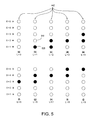
- FIG. 5 shows status indicators of the user interface of FIG. 4 that demonstrate a first embodiment of an illumination scheme for indicating M fan speeds on N status indicators, where M is greater than N, according to the present invention
- FIG. 6 shows status indicators of the user interface of FIG. 4 that demonstrate a second embodiment of an illumination scheme for indicating M fan speeds on N status indicators, where M is greater than N, according to the present invention.
- FIG. 7 shows status indicators of the user interface of FIG. 4 that demonstrate a third embodiment of an illumination scheme for indicating M fan speeds on N status indicators, where M is greater than N, according to the present invention.
- FIG. 2 A block diagram of a system 100 for independent control of lights and motors is shown in FIG. 2 .
- the system includes a plurality of wallstations 104 that are connected in series between an AC voltage source 102 and a light/motor control unit 106 .
- the light/motor control unit 106 is operable to control both the speed of a motor load 108 and the intensity of a lighting load 109 .
- the light/motor control unit 106 may provide continuously variable speed control of the fan motor 108 , or may provide discrete variable speed control of the fan motor.
- a circuit for continuously variable fan speed control is described in the co-pending “Motor Speed Control” application.
- FIG. 3 A simplified block diagram of the wallstation 104 is shown in FIG. 3 .
- a power supply 110 is provided in series between a first electrical terminal H 1 and a second electrical terminal H 2 .
- the power supply 110 provides a DC voltage, V CC , to power a controller 112 .
- the power supply 110 of the wallstation 104 is described in greater detail in the co-pending “Power Supply” application.
- the controller 112 is preferably implemented as a microcontroller, but may be any suitable processing device, such as a programmable logic device (PLD), a microprocessor, or an application specific integrated circuit (ASIC).
- PLD programmable logic device
- ASIC application specific integrated circuit
- a user interface 114 includes a plurality of buttons for receiving inputs from a user and a plurality of status indicators, e.g., light emitting diodes (LEDs), for providing feedback to the user.
- the controller 112 accepts control inputs from the buttons of the user interface 114 and controls the operation of the LEDs.
- the controller 112 is also coupled to a communication circuit 116 for transmitting and receiving control information to and from the light/motor control unit 106 and the other wallstations 104 of system 100 .
- the communication circuit 116 transmits and receives the control information via a communications transformer 118 over the hot line, which is coupled from the AC voltage source 102 via the wallstations 104 to the light/motor control unit 106 .
- the communications transformer 118 has a primary winding 118 A that is connected in series electrical connection with the terminals H 1 , H 2 of the wallstation 104 , and a secondary winding 118 B that is coupled to the communication circuit 116 .
- the communication scheme of the system 100 for independent control of lights and motors is described in greater detail in the co-pending “System” application.
- FIG. 4 shows the user interface 114 of the wallstation 104 of the system 100 of FIG. 2 .
- the wallstation 104 includes a faceplate 410 and a bezel 412 , on which the components of the user interface 114 are provided.
- the user interface 114 includes a first toggle actuator 420 , which is marked with a light bulb icon 422 , and allows the user to toggle the lighting load 109 on and off.
- a second toggle actuator 424 is marked with a fan icon 426 and allows the user to toggle the fan motor 108 on and off.
- Adjacent to the first toggle actuator 420 and the second toggle actuator 424 is a first adjustment actuator 430 and a second adjustment actuator 432 , respectively.
- Pressing the upper portion of the first adjustment actuator 430 causes the intensity of the lighting load 109 to increase and pressing the lower portion causes the intensity to decrease. Similarly, pressing the upper and lower portions of the second adjustment actuator 432 causes the speed of the fan motor 108 to increase and decrease, respectively.
- the user interface 114 also includes a first group of status indicators 440 adjacent the first actuator 420 and a second group of status indicators 442 adjacent the second actuator 424 . As shown in FIG. 4 , each group of status indicators comprises five light emitting diodes (LEDs) in a linear array. The first group of status indicators 440 collectively display the intensity of the lighting load and the second group of status indicators 442 collectively display the speed of the fan motor. The first group of status indicators 440 display the intensity of the lighting load 109 in the same manner as the status indicators 20 of the prior art dimmer 10 of FIG. 1 .
- LEDs light emitting diodes
- the status indicators 442 may operate to illuminate a percentage of the status indicators that corresponds to the present speed of the motor as a percentage of the maximum speed (i.e., in a manner similar to the operation of the status indicators 20 of the prior art dimmer 10 of FIG. 1 ). If the light/motor control unit 106 allows for the selection of a number of discrete speeds of the fan motor 108 that is equal to the number of status indicators 442 (e.g., five in FIG. 4 ), then preferably only one status indicator is lit to designate each discrete speed of the fan motor. When the fan motor is off, all status indicators will be off. However, when the number of discrete fan speeds exceeds the number of status indicators 442 , then each discrete fan speed can no longer be uniquely represented by a single status indicator.
- FIG. 5 demonstrates a first embodiment for illuminating the status indicators 442 to indicate M fan speeds on N status indicators, where M is greater than N.
- the number N of status indicators 442 is five, while the number M of discrete fan speeds is nine.
- the status indicators 442 are arranged in a linear array with each individual status indicator, X, having a value of 1 ⁇ X ⁇ N.
- a non-illuminated status indicator 510 is designated by a white circle and a fully illuminated status indicator 520 is designated by a black circle.
- two status indicators are illuminated for some of the fan motor speeds (i.e., when L is even), as shown in FIGS. 5( c ), 5 ( e ), 5 ( g ), and 5 ( i ).
- the two illuminated status indicators are those that are also illuminated for the next higher speed (i.e., L+1) and next lower speed (i.e., L ⁇ 1).
- L+1 next higher speed
- L ⁇ 1 next lower speed
- the two bottom status indicators are illuminated as shown in FIG. 5( c ).
- FIG. 5 For the embodiment of FIG. 5 , nine different configurations of illuminated status indicators are possible, and thus, nine different fan speeds can be identified using only the five status indicators 442 of the user interface 114 . As increasingly greater discrete fan speeds are chosen, successively higher status indicators are illuminated as shown in FIGS. 5( b ) to 5 ( j ). However, the embodiment as described with reference to FIG. 5 need not be limited to five status indicators and nine fan speeds.
- FIG. 6 demonstrates a second embodiment for illuminating the status indicators 442 to indicate M fan speeds on N status indicators, where M is greater than N.
- the number N of status indicators 442 is five, while the number M of discrete fan speeds is seven.
- a dimly illuminated status indicator 530 is designated by a crosshatched circle. The dimly illuminated status indicator 530 is illuminated at an intensity level that is less than the intensity level of the fully illuminated status indicator 520 , but substantially different in intensity, such that the user of the load control device is able to distinguish the difference in the intensities of the dimly illuminated status indicator and the fully illuminated status indicator.
- the method of FIG. 6 attempts to illuminate three consecutive status indicators X 1 , X 2 , X 3 for each discrete speed.
- the middle of the three status indicators X 2 is fully illuminated, while the two surrounding status indicators X 1 , X 3 are dimly illuminated as shown in FIG. 6( d ).
- the group of three consecutive illuminated status indicators “moves” up and down the linear array as the fan speed is increased and decreased, respectively.
- FIG. 6 For the embodiment of FIG. 6 , seven different configurations of status indicators to indicate seven different fan speeds are possible with the five status indicators 442 of the user interface 114 . As increasingly greater discrete fan speeds are chosen, successively higher status indicators are illuminated as shown in FIGS. 6( b ) to 6 ( h ).
- the embodiment as described with reference to FIG. 6 need not be limited to using five status indicators and seven fan speeds.
- the number of fan speeds that can be displayed on the status indicators is not limited to utilizing one fully illuminated status indicator surrounded by two dimly illuminated status indicators. For example, all three of the consecutively illuminated status indicators could be fully illuminated.
- FIG. 7 shows a third embodiment for illuminating the status indicators 442 to indicate M fan speeds on N status indicators, where M is greater than N.
- the number N of status indicators 442 is five, while the number M of discrete fan speeds is eight.
- multiple fan speeds are indicated by the same configurations of status indicators.
- FIG. 7 eight configurations of status indicators (even though some configurations of status indicators are identical) and seven different fan speeds are possible with the five status indicators 442 of the user interface 114 . As increasingly greater fan speeds are chosen, successively higher status indicators are illuminated as shown in FIGS. 7( b ) to 7 ( i ).
- the embodiment as described with reference to FIG. 7 is not limited to five status indicators and eight fan speeds.
Landscapes
- Physics & Mathematics (AREA)
- General Physics & Mathematics (AREA)
- Engineering & Computer Science (AREA)
- Theoretical Computer Science (AREA)
- Circuit Arrangement For Electric Light Sources In General (AREA)
Abstract
Description
X 1=(L+1)/2. (Equation 1)
X 1 =L/2; X 2 =L/2+1. (Equation 2)
The status indicators that are illuminated for even and odd values of L are summarized in the table below.
| TABLE 1 | ||
| Motor Speed | Illuminated Status Indicators | |
| (L) | (X1, X2) | Notes |
| L is odd | X1 = (L + 1)/2 | Only one status indicator is |
| illuminated. | ||
| L is even | X1 = L/2; X2 = L/2 + 1 | Two status indicators are |
| illuminated. | ||
M=2*N−1, (Equation 3)
where M is the number of fan speeds and N is the number of status indicators.
X 1 =L−2; X 2 =L−1; X 3 =L. (Equation 4)
| TABLE 2 | ||
| Motor Speed | Illuminated Status | |
| (L) | Indicators (X1, X2, X3) | Notes |
| 1 | X1 = 1 | Only the lowest status |
| indicator is illuminated. | ||
| 2 | X1 = 1; X2 = 2 | Only the two lowest status |
| indicators are illuminated. | ||
| 3 ≦ L < M − 1 | X1 = L − 2; X2 = L − 1; | Only three consecutive status |
| X3 = L | indicators are illuminated. | |
| M − 1 | X1 = N − 1; X2 = N | Only the two highest status |
| indicators are illuminated. | ||
| M | X1 = N | Only the highest status |
| indicator is illuminated. | ||
Summarizing further, for all motor speeds L,
X 1 =L−2; X 2 =L−1; X 3 =L for 1≦L≦M, (Equation 5)
and X1, X2, X3 are lit if and only if 1≦X≦N.
M=(N+2), (Equation 6)
where M is the number of discrete fan speeds and N is the number of status indicators. Further, the number of fan speeds that can be displayed on the status indicators is not limited to utilizing one fully illuminated status indicator surrounded by two dimly illuminated status indicators. For example, all three of the consecutively illuminated status indicators could be fully illuminated.
X=FLOOR[(L+2)/2], (Equation 7)
where the function FLOOR(A) is equal to the largest integer less than A.
M=2*N−2, (Equation 8)
where M is the number of fan speeds and N is the number of status indicators.
X=FLOOR[{L+2*(K−1)}/K], (Equation 9)
where 1≦L≦M. Further, the total number of fan speeds M that can be displayed is increased to
M=K*(N−2)+2. (Equation 10)
Claims (12)
Priority Applications (2)
| Application Number | Priority Date | Filing Date | Title |
|---|---|---|---|
| US11/191,780 US7312695B2 (en) | 2005-06-06 | 2005-07-28 | Apparatus and method for displaying operating characteristics on status indicators |
| PCT/US2006/029380 WO2007016332A2 (en) | 2005-07-28 | 2006-07-27 | Apparatus and method for displaying operating characteristics on status indicators |
Applications Claiming Priority (4)
| Application Number | Priority Date | Filing Date | Title |
|---|---|---|---|
| US68768905P | 2005-06-06 | 2005-06-06 | |
| US68782805P | 2005-06-06 | 2005-06-06 | |
| US68769105P | 2005-06-06 | 2005-06-06 | |
| US11/191,780 US7312695B2 (en) | 2005-06-06 | 2005-07-28 | Apparatus and method for displaying operating characteristics on status indicators |
Publications (2)
| Publication Number | Publication Date |
|---|---|
| US20060272569A1 US20060272569A1 (en) | 2006-12-07 |
| US7312695B2 true US7312695B2 (en) | 2007-12-25 |
Family
ID=37607414
Family Applications (1)
| Application Number | Title | Priority Date | Filing Date |
|---|---|---|---|
| US11/191,780 Expired - Lifetime US7312695B2 (en) | 2005-06-06 | 2005-07-28 | Apparatus and method for displaying operating characteristics on status indicators |
Country Status (2)
| Country | Link |
|---|---|
| US (1) | US7312695B2 (en) |
| WO (1) | WO2007016332A2 (en) |
Cited By (30)
| Publication number | Priority date | Publication date | Assignee | Title |
|---|---|---|---|---|
| US20070247089A1 (en) * | 2004-07-15 | 2007-10-25 | E Light Limited | Lighting system and controller |
| US20080111501A1 (en) * | 2006-11-13 | 2008-05-15 | Lutron Electronics Co., Inc. | Wall-mountable smart dual load control device |
| US20090256483A1 (en) * | 2006-06-08 | 2009-10-15 | Lutron Electronics Co., Inc. | Load Control Device Having a Visual Indication of an Energy Savings Mode |
| US20100127626A1 (en) * | 2008-11-25 | 2010-05-27 | Lutron Electronics Co., Inc. | Load Control Device Having A Visual Indication of Energy Savings and Usage Information |
| US20100141169A1 (en) * | 2007-03-30 | 2010-06-10 | Holdip Limited | Lighting systems |
| US20100175973A1 (en) * | 2009-01-15 | 2010-07-15 | Leviton Manufacturing Co., Inc. | Electrical device controller having a switch and a thumbwheel dimmer |
| US20110162946A1 (en) * | 2008-11-25 | 2011-07-07 | Lutron Electronics Co., Inc. | Load Control Device Having A Visual Indication of Energy Savings and Usage Information |
| US7985937B2 (en) * | 2007-07-18 | 2011-07-26 | Leviton Manufacturing Co., Ltd. | Dimmer switch |
| USD703623S1 (en) * | 2013-02-05 | 2014-04-29 | Lutron Electronics Co., Inc. | Load control device |
| USD704153S1 (en) * | 2013-02-05 | 2014-05-06 | Lutron Electronics Co., Inc. | Tabletop remote load control device |
| USD704152S1 (en) * | 2013-02-05 | 2014-05-06 | Lutron Electronices Co., Inc. | Remote control |
| USD711838S1 (en) * | 2013-08-08 | 2014-08-26 | Lutron Electronics Co., Inc. | Load control device |
| USD713361S1 (en) * | 2013-08-08 | 2014-09-16 | Lutron Electronic Co., Inc. | Tabletop remote load control device |
| USD713360S1 (en) * | 2013-08-08 | 2014-09-16 | Lutron Electronics Co., Inc. | Remote control |
| USD722982S1 (en) * | 2012-01-09 | 2015-02-24 | Lutron Electronics Co., Inc. | Dimmer switch |
| US9110449B1 (en) | 2010-04-16 | 2015-08-18 | Cooper Technologies Company | Lighting control device with demand response indicator |
| USD736718S1 (en) * | 2014-04-17 | 2015-08-18 | Lutron Electronics Co., Inc. | Load control device |
| USD737223S1 (en) * | 2014-04-17 | 2015-08-25 | Lutron Electronics Co., Inc. | Remote control |
| USD737222S1 (en) * | 2014-04-17 | 2015-08-25 | Lutron Electronics Co., Inc. | Load control device |
| US9124193B2 (en) | 2008-10-08 | 2015-09-01 | Holdip Limited | Power adaptors |
| USD738321S1 (en) * | 2014-04-17 | 2015-09-08 | Lutron Electronics Co., Inc. | Remote control |
| USD738320S1 (en) | 2014-04-17 | 2015-09-08 | Lutron Electronics Co., Inc. | Tabletop remote load control device |
| USD738328S1 (en) * | 2014-04-17 | 2015-09-08 | Lutron Electronics Co., Inc. | Buttons for a load control device |
| USD739830S1 (en) * | 2014-04-17 | 2015-09-29 | Lutron Electronics Co., Inc. | Buttons for a load control device |
| USD767508S1 (en) * | 2014-12-16 | 2016-09-27 | Lutron Electronics Co., Inc | Tabletop remote load control device |
| USD781245S1 (en) * | 2015-12-22 | 2017-03-14 | Panasonic Intellectual Property Management Co., Ltd. | Dimmer switch |
| USD781792S1 (en) * | 2015-12-21 | 2017-03-21 | Panasonic Intellectual Property Management Co., Ltd. | Dimmer switch |
| US9736894B2 (en) | 2013-12-12 | 2017-08-15 | Verdi Vision Limited | Improvements relating to power adaptors |
| USD799432S1 (en) * | 2016-10-27 | 2017-10-10 | Hunter Fan Company | Wall controller |
| US10790762B2 (en) | 2013-05-23 | 2020-09-29 | Adp Corporate Limited | Relating to power adaptors |
Families Citing this family (8)
| Publication number | Priority date | Publication date | Assignee | Title |
|---|---|---|---|---|
| US7511628B2 (en) * | 2005-05-16 | 2009-03-31 | Lutron Electronics Co., Inc. | Status indicator circuit for a dimmer switch |
| US7837344B2 (en) * | 2006-03-17 | 2010-11-23 | Lutron Electronics Co., Inc. | Traditional-opening dimmer switch having a multi-functional button |
| US7670039B2 (en) * | 2006-03-17 | 2010-03-02 | Lutron Electronics Co., Inc. | Status indicator lens and light pipe structure for a dimmer switch |
| US7573208B2 (en) * | 2007-03-05 | 2009-08-11 | Lutron Electronics Co., Inc. | Method of programming a lighting preset from a radio-frequency remote control |
| USD669038S1 (en) * | 2011-06-16 | 2012-10-16 | Lutron Electronics Co., Inc. | Multi-zone tabletop remote load control device |
| US8866392B2 (en) * | 2011-08-31 | 2014-10-21 | Chia-Teh Chen | Two-level LED security light with motion sensor |
| US20170142807A1 (en) * | 2015-11-12 | 2017-05-18 | Eaton Corporation | Dimmer control and lighting system including the same |
| WO2021041727A1 (en) * | 2019-08-27 | 2021-03-04 | Lutron Technology Company Llc | Control device having a visible indicator |
Citations (15)
| Publication number | Priority date | Publication date | Assignee | Title |
|---|---|---|---|---|
| US3959791A (en) | 1974-04-04 | 1976-05-25 | Yashica Co., Ltd. | Digital display systems |
| FR2381360A1 (en) | 1977-02-22 | 1978-09-15 | Smiths Industries Ltd | ANALOGUE ELECTRIC INDICATOR WITH LUMINOUS DISPLAY |
| GB2085164A (en) | 1980-10-08 | 1982-04-21 | Ird Mechanalysis | Machine monitoring system and apparatus |
| JPS5876770A (en) | 1981-10-31 | 1983-05-09 | Japan Aviation Electronics Ind Ltd | Digital lighting indicator |
| JPS58127171A (en) | 1982-01-26 | 1983-07-28 | Sony Corp | Level indicator |
| US5399940A (en) | 1992-03-31 | 1995-03-21 | Lutron Electronics Co., Inc. | Lighting indicating device having plural illuminating elements with all such elements being illuminated with one being greater than the others |
| US5430356A (en) | 1993-10-05 | 1995-07-04 | Lutron Electronics Co., Inc. | Programmable lighting control system with normalized dimming for different light sources |
| US5909087A (en) * | 1996-03-13 | 1999-06-01 | Lutron Electronics Co. Inc. | Lighting control with wireless remote control and programmability |
| US6690268B2 (en) * | 2000-03-02 | 2004-02-10 | Donnelly Corporation | Video mirror systems incorporating an accessory module |
| US6968707B2 (en) * | 2003-12-02 | 2005-11-29 | Electrolux Home Products, Inc. | Variable speed, electronically controlled, room air conditioner |
| US6984900B1 (en) * | 1998-10-09 | 2006-01-10 | Azoteq (Pty) Ltd. | Intelligent electrical switch |
| US20060255959A1 (en) * | 2005-05-16 | 2006-11-16 | Lutron Electronics Co., Inc. | Status indicator circuit for a dimmer switch |
| US20060284734A1 (en) * | 2005-06-06 | 2006-12-21 | Lutron Electronics Co., Inc. | Remote control lighting control system |
| US7190125B2 (en) * | 2004-07-15 | 2007-03-13 | Lutron Electronics Co., Inc. | Programmable wallbox dimmer |
| US20070110192A1 (en) * | 2005-06-06 | 2007-05-17 | Steiner James P | Method of communicating between control devices of a load control system |
-
2005
- 2005-07-28 US US11/191,780 patent/US7312695B2/en not_active Expired - Lifetime
-
2006
- 2006-07-27 WO PCT/US2006/029380 patent/WO2007016332A2/en not_active Ceased
Patent Citations (15)
| Publication number | Priority date | Publication date | Assignee | Title |
|---|---|---|---|---|
| US3959791A (en) | 1974-04-04 | 1976-05-25 | Yashica Co., Ltd. | Digital display systems |
| FR2381360A1 (en) | 1977-02-22 | 1978-09-15 | Smiths Industries Ltd | ANALOGUE ELECTRIC INDICATOR WITH LUMINOUS DISPLAY |
| GB2085164A (en) | 1980-10-08 | 1982-04-21 | Ird Mechanalysis | Machine monitoring system and apparatus |
| JPS5876770A (en) | 1981-10-31 | 1983-05-09 | Japan Aviation Electronics Ind Ltd | Digital lighting indicator |
| JPS58127171A (en) | 1982-01-26 | 1983-07-28 | Sony Corp | Level indicator |
| US5399940A (en) | 1992-03-31 | 1995-03-21 | Lutron Electronics Co., Inc. | Lighting indicating device having plural illuminating elements with all such elements being illuminated with one being greater than the others |
| US5430356A (en) | 1993-10-05 | 1995-07-04 | Lutron Electronics Co., Inc. | Programmable lighting control system with normalized dimming for different light sources |
| US5909087A (en) * | 1996-03-13 | 1999-06-01 | Lutron Electronics Co. Inc. | Lighting control with wireless remote control and programmability |
| US6984900B1 (en) * | 1998-10-09 | 2006-01-10 | Azoteq (Pty) Ltd. | Intelligent electrical switch |
| US6690268B2 (en) * | 2000-03-02 | 2004-02-10 | Donnelly Corporation | Video mirror systems incorporating an accessory module |
| US6968707B2 (en) * | 2003-12-02 | 2005-11-29 | Electrolux Home Products, Inc. | Variable speed, electronically controlled, room air conditioner |
| US7190125B2 (en) * | 2004-07-15 | 2007-03-13 | Lutron Electronics Co., Inc. | Programmable wallbox dimmer |
| US20060255959A1 (en) * | 2005-05-16 | 2006-11-16 | Lutron Electronics Co., Inc. | Status indicator circuit for a dimmer switch |
| US20060284734A1 (en) * | 2005-06-06 | 2006-12-21 | Lutron Electronics Co., Inc. | Remote control lighting control system |
| US20070110192A1 (en) * | 2005-06-06 | 2007-05-17 | Steiner James P | Method of communicating between control devices of a load control system |
Non-Patent Citations (1)
| Title |
|---|
| European Patent Office, International Search Report and Written Opinion, Feb. 14, 2007, 14 pages. |
Cited By (54)
| Publication number | Priority date | Publication date | Assignee | Title |
|---|---|---|---|---|
| US20070247089A1 (en) * | 2004-07-15 | 2007-10-25 | E Light Limited | Lighting system and controller |
| US20090256483A1 (en) * | 2006-06-08 | 2009-10-15 | Lutron Electronics Co., Inc. | Load Control Device Having a Visual Indication of an Energy Savings Mode |
| US20080111501A1 (en) * | 2006-11-13 | 2008-05-15 | Lutron Electronics Co., Inc. | Wall-mountable smart dual load control device |
| US8242711B2 (en) | 2007-03-30 | 2012-08-14 | Hold IP Limited | Lighting systems |
| US20100141169A1 (en) * | 2007-03-30 | 2010-06-10 | Holdip Limited | Lighting systems |
| US7985937B2 (en) * | 2007-07-18 | 2011-07-26 | Leviton Manufacturing Co., Ltd. | Dimmer switch |
| US9888533B2 (en) | 2008-10-08 | 2018-02-06 | Holdip Limited | Power adaptors |
| US9124193B2 (en) | 2008-10-08 | 2015-09-01 | Holdip Limited | Power adaptors |
| US20110162946A1 (en) * | 2008-11-25 | 2011-07-07 | Lutron Electronics Co., Inc. | Load Control Device Having A Visual Indication of Energy Savings and Usage Information |
| US8274233B2 (en) | 2008-11-25 | 2012-09-25 | Lutron Electronics Co., Inc. | Load control device having a visual indication of energy savings and usage information |
| US8049427B2 (en) | 2008-11-25 | 2011-11-01 | Lutron Electronics Co., Inc. | Load control device having a visual indication of energy savings and usage information |
| US20100127626A1 (en) * | 2008-11-25 | 2010-05-27 | Lutron Electronics Co., Inc. | Load Control Device Having A Visual Indication of Energy Savings and Usage Information |
| US8796940B2 (en) | 2008-11-25 | 2014-08-05 | Lutron Electronics Co., Inc. | Control device for providing a visual indication of energy savings and usage information |
| US20100175973A1 (en) * | 2009-01-15 | 2010-07-15 | Leviton Manufacturing Co., Inc. | Electrical device controller having a switch and a thumbwheel dimmer |
| US8124898B2 (en) * | 2009-01-15 | 2012-02-28 | Leviton Manufacturing Co., Inc. | Electrical device controller having a switch and a thumbwheel dimmer |
| US9110449B1 (en) | 2010-04-16 | 2015-08-18 | Cooper Technologies Company | Lighting control device with demand response indicator |
| USD722982S1 (en) * | 2012-01-09 | 2015-02-24 | Lutron Electronics Co., Inc. | Dimmer switch |
| USD703623S1 (en) * | 2013-02-05 | 2014-04-29 | Lutron Electronics Co., Inc. | Load control device |
| USD733668S1 (en) | 2013-02-05 | 2015-07-07 | Lutron Electronics Co., Inc. | Buttons for a remote control |
| USD704152S1 (en) * | 2013-02-05 | 2014-05-06 | Lutron Electronices Co., Inc. | Remote control |
| USD704153S1 (en) * | 2013-02-05 | 2014-05-06 | Lutron Electronics Co., Inc. | Tabletop remote load control device |
| US10790762B2 (en) | 2013-05-23 | 2020-09-29 | Adp Corporate Limited | Relating to power adaptors |
| USD713360S1 (en) * | 2013-08-08 | 2014-09-16 | Lutron Electronics Co., Inc. | Remote control |
| USD713361S1 (en) * | 2013-08-08 | 2014-09-16 | Lutron Electronic Co., Inc. | Tabletop remote load control device |
| USD711838S1 (en) * | 2013-08-08 | 2014-08-26 | Lutron Electronics Co., Inc. | Load control device |
| US9736894B2 (en) | 2013-12-12 | 2017-08-15 | Verdi Vision Limited | Improvements relating to power adaptors |
| USD738321S1 (en) * | 2014-04-17 | 2015-09-08 | Lutron Electronics Co., Inc. | Remote control |
| USD774470S1 (en) | 2014-04-17 | 2016-12-20 | Lutron Electonics Co., Inc. | Remote control |
| USD738328S1 (en) * | 2014-04-17 | 2015-09-08 | Lutron Electronics Co., Inc. | Buttons for a load control device |
| USD739830S1 (en) * | 2014-04-17 | 2015-09-29 | Lutron Electronics Co., Inc. | Buttons for a load control device |
| USD754617S1 (en) | 2014-04-17 | 2016-04-26 | Lutron Electronics Co., Inc. | Remote control |
| USD755133S1 (en) | 2014-04-17 | 2016-05-03 | Lutron Electronics Co., Inc. | Buttons for a load control device |
| USD755738S1 (en) | 2014-04-17 | 2016-05-10 | Lutron Electronics Co., Inc. | Tabletop remote load control device |
| USD755737S1 (en) | 2014-04-17 | 2016-05-10 | Lutron Electronics Co., Inc. | Tabletop remote load control device |
| USD755736S1 (en) | 2014-04-17 | 2016-05-10 | Lutron Electronics Co., Inc. | Remote control |
| USD755739S1 (en) | 2014-04-17 | 2016-05-10 | Lutron Electronics Co., Inc. | Buttons for a load control device |
| USD736718S1 (en) * | 2014-04-17 | 2015-08-18 | Lutron Electronics Co., Inc. | Load control device |
| USD768581S1 (en) | 2014-04-17 | 2016-10-11 | Lutron Electronics Co., Inc. | Remote control |
| USD770394S1 (en) * | 2014-04-17 | 2016-11-01 | Lutron Electronics Co., Inc. | Load control device |
| USD738320S1 (en) | 2014-04-17 | 2015-09-08 | Lutron Electronics Co., Inc. | Tabletop remote load control device |
| USD777684S1 (en) | 2014-04-17 | 2017-01-31 | Lutron Electronics Co., Inc | Tabletop remote load control device |
| USD737223S1 (en) * | 2014-04-17 | 2015-08-25 | Lutron Electronics Co., Inc. | Remote control |
| USD737222S1 (en) * | 2014-04-17 | 2015-08-25 | Lutron Electronics Co., Inc. | Load control device |
| USD794580S1 (en) | 2014-12-16 | 2017-08-15 | Lutron Electronics Co., Inc. | Tabletop remote load control device |
| USD795202S1 (en) | 2014-12-16 | 2017-08-22 | Lutron Electronics Co., Inc. | Tabletop remote load control device |
| USD867308S1 (en) | 2014-12-16 | 2019-11-19 | Lutron Technology Company Llc | Tabletop remote load control device |
| USD767508S1 (en) * | 2014-12-16 | 2016-09-27 | Lutron Electronics Co., Inc | Tabletop remote load control device |
| USD899383S1 (en) | 2014-12-16 | 2020-10-20 | Lutron Technology Company Llc | Tabletop remote load control device |
| USD929350S1 (en) | 2014-12-16 | 2021-08-31 | Lutron Technology Company Llc | Tabletop remote load control device |
| USD975662S1 (en) | 2014-12-16 | 2023-01-17 | Lutron Technology Company Llc | Table top remote load control device |
| USD781792S1 (en) * | 2015-12-21 | 2017-03-21 | Panasonic Intellectual Property Management Co., Ltd. | Dimmer switch |
| USD781245S1 (en) * | 2015-12-22 | 2017-03-14 | Panasonic Intellectual Property Management Co., Ltd. | Dimmer switch |
| USD799432S1 (en) * | 2016-10-27 | 2017-10-10 | Hunter Fan Company | Wall controller |
| USD892063S1 (en) | 2016-10-27 | 2020-08-04 | Hunter Fan Company | Wall controller |
Also Published As
| Publication number | Publication date |
|---|---|
| US20060272569A1 (en) | 2006-12-07 |
| WO2007016332A3 (en) | 2007-04-05 |
| WO2007016332A2 (en) | 2007-02-08 |
Similar Documents
| Publication | Publication Date | Title |
|---|---|---|
| US7312695B2 (en) | Apparatus and method for displaying operating characteristics on status indicators | |
| US11564293B2 (en) | User interface for controlling intensity and color of a lighting load | |
| US8049427B2 (en) | Load control device having a visual indication of energy savings and usage information | |
| US8274233B2 (en) | Load control device having a visual indication of energy savings and usage information | |
| US4889999A (en) | Master electrical load control system | |
| EP2243337B1 (en) | User interface for scene setting control with light balance | |
| KR101981714B1 (en) | Controller and solid state lighting device for large area applications | |
| RU2526863C2 (en) | User interface device for controlling consumer load and lighting system using said user interface device | |
| EP1774833B1 (en) | Lighting system and controller | |
| JP2000516024A (en) | Wall mountable control system with virtually unlimited bandwidth capacity | |
| JP5406542B2 (en) | Lighting device | |
| CN119138104A (en) | System and method for generating a customized color temperature dimming curve for a lighting device | |
| JP2011171006A (en) | Lighting system | |
| CN216976750U (en) | Lighting device | |
| CA2339723A1 (en) | Device for controlling light sources having a ballast | |
| US11483908B1 (en) | 3-way dimming brightness and color temperature control | |
| JP5932497B2 (en) | LED lighting device | |
| KR20150107673A (en) | Dimming apparatus, and illumination system using same | |
| KR102275953B1 (en) | LED lighting system | |
| US10757777B1 (en) | Brightness adjustment for a white-light lamp | |
| CN212086545U (en) | Driver for LED track lamp and LED track lamp | |
| US20260025888A1 (en) | Method of controlling a multi-channel light-emitting diode light source | |
| JP5663055B2 (en) | Lighting device and lighting device | |
| US20250031288A1 (en) | Load Control Device for a Light-Emitting Diode Light Source | |
| KR20200002621U (en) | A Brightness or Dimming Selecting Type of a Lighting Apparatus |
Legal Events
| Date | Code | Title | Description |
|---|---|---|---|
| AS | Assignment |
Owner name: LUTRON ELECTRONICS CO., INC., PENNSYLVANIA Free format text: ASSIGNMENT OF ASSIGNORS INTEREST;ASSIGNORS:LEHMER, MATTHEW J.;BORING, NATHAN;DOBBINS, AARON;REEL/FRAME:017684/0510;SIGNING DATES FROM 20060307 TO 20060308 |
|
| STCF | Information on status: patent grant |
Free format text: PATENTED CASE |
|
| FPAY | Fee payment |
Year of fee payment: 4 |
|
| FPAY | Fee payment |
Year of fee payment: 8 |
|
| MAFP | Maintenance fee payment |
Free format text: PAYMENT OF MAINTENANCE FEE, 12TH YEAR, LARGE ENTITY (ORIGINAL EVENT CODE: M1553); ENTITY STATUS OF PATENT OWNER: LARGE ENTITY Year of fee payment: 12 |
|
| AS | Assignment |
Owner name: LUTRON TECHNOLOGY COMPANY LLC, PENNSYLVANIA Free format text: ASSIGNMENT OF ASSIGNORS INTEREST;ASSIGNOR:LUTRON ELECTRONICS CO., INC.;REEL/FRAME:049286/0001 Effective date: 20190304 |