US731007A - Power-translating device. - Google Patents
Power-translating device. Download PDFInfo
- Publication number
- US731007A US731007A US10984302A US1902109843A US731007A US 731007 A US731007 A US 731007A US 10984302 A US10984302 A US 10984302A US 1902109843 A US1902109843 A US 1902109843A US 731007 A US731007 A US 731007A
- Authority
- US
- United States
- Prior art keywords
- disks
- friction
- shaft
- driven
- driving
- Prior art date
- Legal status (The legal status is an assumption and is not a legal conclusion. Google has not performed a legal analysis and makes no representation as to the accuracy of the status listed.)
- Expired - Lifetime
Links
- 230000002093 peripheral effect Effects 0.000 description 8
- XEEYBQQBJWHFJM-UHFFFAOYSA-N Iron Chemical compound [Fe] XEEYBQQBJWHFJM-UHFFFAOYSA-N 0.000 description 2
- 229910000746 Structural steel Inorganic materials 0.000 description 1
- 230000009194 climbing Effects 0.000 description 1
- 229910052742 iron Inorganic materials 0.000 description 1
Images


Classifications
-
- F—MECHANICAL ENGINEERING; LIGHTING; HEATING; WEAPONS; BLASTING
- F16—ENGINEERING ELEMENTS AND UNITS; GENERAL MEASURES FOR PRODUCING AND MAINTAINING EFFECTIVE FUNCTIONING OF MACHINES OR INSTALLATIONS; THERMAL INSULATION IN GENERAL
- F16H—GEARING
- F16H15/00—Gearings for conveying rotary motion with variable gear ratio, or for reversing rotary motion, by friction between rotary members
- F16H15/02—Gearings for conveying rotary motion with variable gear ratio, or for reversing rotary motion, by friction between rotary members without members having orbital motion
- F16H15/04—Gearings providing a continuous range of gear ratios
- F16H15/06—Gearings providing a continuous range of gear ratios in which a member A of uniform effective diameter mounted on a shaft may co-operate with different parts of a member B
- F16H15/08—Gearings providing a continuous range of gear ratios in which a member A of uniform effective diameter mounted on a shaft may co-operate with different parts of a member B in which the member B is a disc with a flat or approximately flat friction surface
- F16H15/10—Gearings providing a continuous range of gear ratios in which a member A of uniform effective diameter mounted on a shaft may co-operate with different parts of a member B in which the member B is a disc with a flat or approximately flat friction surface in which the axes of the two members cross or intersect
- F16H15/12—Gearings providing a continuous range of gear ratios in which a member A of uniform effective diameter mounted on a shaft may co-operate with different parts of a member B in which the member B is a disc with a flat or approximately flat friction surface in which the axes of the two members cross or intersect in which one or each member is duplicated, e.g. for obtaining better transmission, for lessening the reaction forces on the bearings
-
- Y—GENERAL TAGGING OF NEW TECHNOLOGICAL DEVELOPMENTS; GENERAL TAGGING OF CROSS-SECTIONAL TECHNOLOGIES SPANNING OVER SEVERAL SECTIONS OF THE IPC; TECHNICAL SUBJECTS COVERED BY FORMER USPC CROSS-REFERENCE ART COLLECTIONS [XRACs] AND DIGESTS
- Y10—TECHNICAL SUBJECTS COVERED BY FORMER USPC
- Y10T—TECHNICAL SUBJECTS COVERED BY FORMER US CLASSIFICATION
- Y10T74/00—Machine element or mechanism
- Y10T74/19—Gearing
- Y10T74/19023—Plural power paths to and/or from gearing
- Y10T74/19042—Friction-type gearing
-
- Y—GENERAL TAGGING OF NEW TECHNOLOGICAL DEVELOPMENTS; GENERAL TAGGING OF CROSS-SECTIONAL TECHNOLOGIES SPANNING OVER SEVERAL SECTIONS OF THE IPC; TECHNICAL SUBJECTS COVERED BY FORMER USPC CROSS-REFERENCE ART COLLECTIONS [XRACs] AND DIGESTS
- Y10—TECHNICAL SUBJECTS COVERED BY FORMER USPC
- Y10T—TECHNICAL SUBJECTS COVERED BY FORMER US CLASSIFICATION
- Y10T74/00—Machine element or mechanism
- Y10T74/19—Gearing
- Y10T74/19219—Interchangeably locked
- Y10T74/19377—Slidable keys or clutches
- Y10T74/19386—Multiple clutch shafts
- Y10T74/19391—Progressive
-
- Y—GENERAL TAGGING OF NEW TECHNOLOGICAL DEVELOPMENTS; GENERAL TAGGING OF CROSS-SECTIONAL TECHNOLOGIES SPANNING OVER SEVERAL SECTIONS OF THE IPC; TECHNICAL SUBJECTS COVERED BY FORMER USPC CROSS-REFERENCE ART COLLECTIONS [XRACs] AND DIGESTS
- Y10—TECHNICAL SUBJECTS COVERED BY FORMER USPC
- Y10T—TECHNICAL SUBJECTS COVERED BY FORMER US CLASSIFICATION
- Y10T74/00—Machine element or mechanism
- Y10T74/19—Gearing
- Y10T74/19219—Interchangeably locked
- Y10T74/19377—Slidable keys or clutches
- Y10T74/19414—Single clutch shaft
- Y10T74/19484—Single speed forward and reverse
- Y10T74/19493—Bevel gears
-
- Y—GENERAL TAGGING OF NEW TECHNOLOGICAL DEVELOPMENTS; GENERAL TAGGING OF CROSS-SECTIONAL TECHNOLOGIES SPANNING OVER SEVERAL SECTIONS OF THE IPC; TECHNICAL SUBJECTS COVERED BY FORMER USPC CROSS-REFERENCE ART COLLECTIONS [XRACs] AND DIGESTS
- Y10—TECHNICAL SUBJECTS COVERED BY FORMER USPC
- Y10T—TECHNICAL SUBJECTS COVERED BY FORMER US CLASSIFICATION
- Y10T74/00—Machine element or mechanism
- Y10T74/19—Gearing
- Y10T74/19642—Directly cooperating gears
- Y10T74/19688—Bevel
- Y10T74/19693—Motor vehicle drive
Definitions
- My invention is susceptible of application to an ordinary road-Wagon or to a car adapted to be propelled along an iron railway-track. It may also be used for transmitting power to any driven device where a variable speed is required from a source of constant speed.
- FIG. 1 is a plan view.
- Fig. 2 is an 'en ⁇ larged broken-away portion of an elevation, in section, of' the translating mechanism', taken through a practically central plane of Fig. 1.
- Fig. 3 is an end elevation '0f-the truck and mechanism applied thereto.
- Fig. 4 is an enlarged broken-away plan view of the translating mechanism.
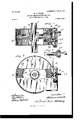
- Fig. 5 is a detail of an enlarged traction-wheel, showing the gear-case applied thereto and the manner in which it is held in position.
- FIG. 6 is a detail of one of the friction disks or wheels of the translating mechanism, showing the means by which the friction-Wheel is shifted in front of the face of the driving frictiondisk.
- Fig. 7 is taken ou a ⁇ central plane through line 7 7 of Fig.” 8.
- Fig. 8 is an enlarged side elevation of the gear-case, partly broken away, showing a portion of the double-tapered gear-Wheel fixed to the driven shaft and the means for changing the speed of the same.
- Fig. 9 is an enlarged brokenaWay det-ail of lthe tumbling-shaft and the universal joint, in section, by which said shafts are connected together.
- a frame for supporting the source ofpower, the translating device, and the running-gear is provided by the side beams l and l, 2 and 2:, 3 and 3 by the cross-bars 4, 4, 4", and 4C.
- Journal-boxes 5 and 5L are supported on the frame and are designed to carry the journals of the shafts or axles 7 7, upon which the traction-Wheels 6 are fixed.
- the motive power is furnished by the engines S and 8, which are designed to run, preferably, at a practically constant speed. These engines are mounted, respectively, upon the side beams 1 and 1tl and are operatively connected together by means of the shaft 9. They are designed to rotate at a uniform and equal speed and in the same direction with reference to each other. Any suitable engine or motor may be substituted for those shown in the drawings.
- Driving friction-disks 10 and 10a are made fast to the shaft or axle 9. The confronting surfaces of the respectivedisks are made parallel and are prepared so as to possess a high frictional' coefficient with the driven disks.
- the shaft 9 passes freely through a T-shaped piece 11, in the lateral projections of which shaft-bearings are provided for the shafts 12 and 13.
- Two parallel angle-iron pieces 15 and l5 are fixed, respectively, to thecross-bars 4L and 4l. Near the ends of these pieces, and preferably immediately over the cross-bars 4a and 4b, are erected two vertical,bearing-brackets 16 and 16a.
- the yoke17 is hinged to the vertical bearing-brackets 16 and 16a at the points 2O and 20a.
- lt is provided with downwardly-extending arms 2l and 21a.
- a shaft 22 is carried by vthe bearings 23, 23a, 23", and
- a yoke 17 by means of the links 25 and 250, respectively.
- a yoke 26 ⁇ surrounds the shaft 9 and the cross-piece 11 and is provided with bearings thereon, the upper end of which is loosely bolted to the downwardly-depending IOO which is connected to the crank-arms 24 and 24" by links 25u and 25", respectively.
- the rod 22 may extend to each end of the car, and any convenient means for oscillating it maybe provided.
- the shafts 12 and 13 are provided, respectively, with splines 12 and 13a.
- Friction-disks 28 and 29 are adapted to be reciprocated over the respective shafts 12 and 13 and to be positively driven by the respective splines 12 and 13:
- Rods 3U and 31 are supported on the brackets 16 and 16 and are adapted to be reciprocated in their bearings.
- the rod 30 extends forward to one end of the car, and the rod 3l extends forward to the opposite end of the car. They may be provided vwith any means for conveniently reciprocating them.
- Each rod is pro-y vided with a rack 3()a and 31, into each of which a transmitting or idler gear-wheel 32 meshes.
- the pivot or axis upon which this gear-Wheel rotates is stationary upon the block 33.
- Each of the friction-wheels 28 and 29 is provided With a grooved collar.
- An upwardlyextending fork 28 is fixed to the rod 3l and enters the grooved collar of the friction-disk 28.V
- a similar upwardly-extending fork 295L is fixed to the rod 30 and enters the grooved collar of the friction-disk 29.
- gear-cases 34 and 34a are carried upon the axles 7 7.
- Each case containsadonble-beveled gear-Wheel 35, which islixed to the respective shafts b v means of a key 36.
- Parallel shafts 37 and 37a enter one side of the case,find bearings therein, and carry tapered pinions 38 and 38, which are located on the respective shafts. These tapered pinions mesh into the teeth on the opposite sides of the tapered gear- Wheel 35.
- the shaft 37 carries a small pinion 39, which is fixed thereto and which meshes into a larger gear-wheel 39, fixed to the shaft 37a.
- the grooved clutch-collar 40 is adapted to be reciprocated on the shaft 37 and is provided with teeth upon the annular surface thatconfronts the tapered pinion 38,which are adapted to engage with similar teeth made integral with the pinion 38.
- a similar grooved collar 40 surrounds the shaft 37 and is adapted to be rotated therewith and to be reciprocated thereon. It is also provided with teeth on the surface confronting the tapered pinion 38a, which are adapted to engage With similar teeth carried by the said pinion.
- arm 41 is adapted to be oscillated upon the axis, as shown, and is provided with a fork Vat each end, which enter the grooves on the respective clutch-collars 40 and 40'.
- a vertical rod 42 passes through the arm 41 and is adapted to oscillate the same.
- an arm 42a is fixed thereto and is loosely supported upon the cross-bar 4f.
- Tumbling-shafts 43 and 43a connect the shafts 12 and 13 with the shafts 37 37.
- Universal joints 44 are provided at each end of the tumbling-shafts and connecting-shafts.
- the shaft 9 may be rotated by theengines 8 and 8iL without transmitting any motion to the tractionwheels.
- the friction-disks 28 and 29 donot, as shown in Fig. 1, make contact with the face of either of the disks 10 or 10, which is necessary for the purpose of transmitting power therefrom to the respective Wheels. Looking at Fig.
- the friction-idlers 28 and 29 are shown in dotted lines to have been moved up to a point nearer the center of the disks 10 and 10a, so that when they make contact with either of the said disks while in this position the vehicle will be driven at a slower speed, but the power torque transmitted to the traction-wheels is proportionately greater.
- the wheels 28 and 29 are reciprocatedin position with reference to the diameter of the disks 10 and 10*L by means of the reciprocating rods 30 and 3l and are caused to move coincidently by virtue of the fact that the transmitting-disk 32, which connects the respective rods together, will cause the opposite rodand its respective disk to move coincidently with the rod which has been primarily reciprocated.
- either rod 30 or 31 may be primarily reciprocated, when the accompanying rod will have'im parted to it asimilar motion of the same extent, whereby its corresponding disk, either 28 or'29, will be moved coincidently and consistently therewith.
- the rod 22 should be oscillated in the opposite direction, so that the crank-arms 24 will move the oscillating system, including the frictiondisks 28 and 29, into frictional contact with the face of the disk 10.
- the vehicle will be propelled in a direction opposite to that which it was propelled when the friction-disks 28 and 29 made contact with the face of the disk 10.
- a device of the class described comprising two driving-disks having confronting parallel friction-surfaces, two intervening driven disks, provided with peripheral friction-surfaces adapted to be coincidently placed in frictional contact with the face of either of the driving-disks.
- a device of the class described comprising two driving-disks havin g confronting parallel friction-surfaces, two intervening driven disks provided with peripheral friction-surfaces, adapted t0 be coincidently placed in frictional contact with the face of either of the drivingdisks,and twoindependent driven shafts upon which the said driven disks are respectively and revoluhly fixed.
- a device of the class described comprising two driving-disks having confronting parallel friction-surfaces, two intervening driven disks provided with peripheral friction-surfaces adapted to be coincidently placed in frictional contact with the face of either of the driving-disks, two independent driven shafts upon which the said driven disks are respectively and revoluhly fixed and upon which they are adapted to be reciprocated, and a means for reciprocating said driven disks on saidnshafts.
- a device of Vthe class described comprising two driving-disks having confronting parallel friction-surfaces, two intervening driven disks provided with peripheral friction-surfaces adapted to be coincidently placed in frictional contact with the face of either of the driving-disks, two independent driven shafts upon which the said driven disks are respectively and revoluhly fixed and upon which they are adapted to be reciprocated, and a means for coincidently reciprocating said driven disks on said shafts in corresponding directions.
- a device of the class described comprising two driven disks having confronting parallel friction-surfaces, twointervenin g driven disks provided with peripheral friction-surfaces adapted to be coincidently placed in frictional contact with the face of either of the driving-disks, a means for coincidently moving said driven disks toward either of said driving-disks, and a means for coincidently and correspondingly moving said driven disks across the face of said driving-disks.
- a device of the class described comprising two motors, a shaft to which said motors are connected in common, two driving-disks having confronting parallel,friction-surfaces mounted on said shaft, two intervening driven disks provided with peripheral friction-surfaces adapted to be coincidently placed in frictional contact with the face of either of the driving-disks, an independent shaft for each of the driven disks upon which said driven disks are adapted to be reciprocated, a means for reciprocatingsaid disks, and a means for coincidently moving the driven disks and their respective shafts toward either of the saidV driving-disks.
- a device of the class described comprising a driving-disk having a friction-surface upon one of its faces, two confronting driven disks provided with peripheral friction-surfaces adapted to be placed in frictional contact with the face of said driving-disks, an independent shaft for each of said driven disks connected to separate devices to be driven, and a means for moving said disks coincidently and correspondingly across the face of the driving-disk.
- the transmitting instrumentality comprising TILLIAM O' VOR l H v5 a shaft having a universal joint at each end Wtnesses:
Landscapes
- Engineering & Computer Science (AREA)
- General Engineering & Computer Science (AREA)
- Mechanical Engineering (AREA)
- Arrangement Or Mounting Of Propulsion Units For Vehicles (AREA)
Description
PATENTED JUNE 16, 1903.
W` o WoETE EoWEE TEANSLATING DEVICE.
f www1 E ,V E E ww ES w Qmm L a W 111111\ l 1M 1. v n 3H EN M s 1| whwn x N Q Se E E E l E@ E E $1 1T 1 M1 D 9E, m
Ms?? v PATENTED JUNE 16, 1903.
W. O. WORTH.v POWER TRANSLATING DEVICE.
APPLIOATION FILED JUNE 2, 1902.
` 4 SHEETS-SHEET 2.
N0 MODEL.
wwwmwa? IIIIIIlV-'IIIIII IIE i um/` lllllllllmllllllllll PATENTED JUNE 16, 1903. W. 0. WORTH. POWER TRANSLATING DEVICE.
APPLIOATION FILED JUNE 2, 1902.
N0 MODEL.
, UNITED STATES` Patented June 16, 1903.
PATENT OFFICE.
WILLIAM O. WORTH, OF CHICAGO, ILLINOIS, ASSIGNOR, BY DIRECT AND MESNE ASSIGNMENTS, TO HIMSELF, AND WILLIAM-R. DONALDSON, OF
LOUISVILLE, KENTUCKY.
POWER-TRANSLATING DEVICE.
SPECIFICATION forming part of Letters Patent No.`731,007, dated June 16, 1993.
. Application filed June 2, 1902.. .Serial-Nn. 109,843. (No model.)
To @ZZ whom 'it may concern.:
Be it known that I, WILLIAM O. WORTH, ofA
power-translating devices; and it has espe-v cial reference to the power-translating devices intervening between the prime mover and the traction-wheels 0f motor-vehicles.
My invention is susceptible of application to an ordinary road-Wagon or to a car adapted to be propelled along an iron railway-track. It may also be used for transmitting power to any driven device where a variable speed is required from a source of constant speed.
The drawings illustrate the application of the inventionto a railway-car, in which-f- Figure 1 is a plan view. Fig, 2 is an 'en` larged broken-away portion of an elevation, in section, of' the translating mechanism', taken through a practically central plane of Fig. 1. Fig. 3 is an end elevation '0f-the truck and mechanism applied thereto. Fig. 4 is an enlarged broken-away plan view of the translating mechanism. Fig. 5 is a detail of an enlarged traction-wheel, showing the gear-case applied thereto and the manner in which it is held in position. Fig. 6 is a detail of one of the friction disks or wheels of the translating mechanism, showing the means by which the friction-Wheel is shifted in front of the face of the driving frictiondisk. Fig. 7 is taken ou a `central plane through line 7 7 of Fig." 8. Fig. 8 is an enlarged side elevation of the gear-case, partly broken away, showing a portion of the double-tapered gear-Wheel fixed to the driven shaft and the means for changing the speed of the same. Fig. 9 is an enlarged brokenaWay det-ail of lthe tumbling-shaft and the universal joint, in section, by which said shafts are connected together.
In all of the views the same numerals of reference indicate similar parts.
A frame for supporting the source ofpower, the translating device, and the running-gear is provided by the side beams l and l, 2 and 2:, 3 and 3 by the cross-bars 4, 4, 4", and 4C.
Journal-boxes 5 and 5L are supported on the frame and are designed to carry the journals of the shafts or axles 7 7, upon which the traction-Wheels 6 are fixed.
The motive power is furnished by the engines S and 8, which are designed to run, preferably, at a practically constant speed. These engines are mounted, respectively, upon the side beams 1 and 1tl and are operatively connected together by means of the shaft 9. They are designed to rotate at a uniform and equal speed and in the same direction with reference to each other. Any suitable engine or motor may be substituted for those shown in the drawings. Driving friction-disks 10 and 10a are made fast to the shaft or axle 9. The confronting surfaces of the respectivedisks are made parallel and are prepared so as to possess a high frictional' coefficient with the driven disks. The shaft 9 passes freely through a T-shaped piece 11, in the lateral projections of which shaft-bearings are provided for the shafts 12 and 13. Two parallel angle-iron pieces 15 and l5 are fixed, respectively, to thecross-bars 4L and 4l. Near the ends of these pieces, and preferably immediately over the cross-bars 4a and 4b, are erected two vertical,bearing-brackets 16 and 16a. A yoke 17, provided with a centrally-located doWnwardly-projecting piece 18, provides bearings 19 and 19a for the respective shafts 12 and 13. The yoke17 is hinged to the vertical bearing-brackets 16 and 16a at the points 2O and 20a. lt is provided with downwardly-extending arms 2l and 21a. A shaft 22 is carried by vthe bearings 23, 23a, 23", and
V23, which are fixed to the angle-piece 15a.
yoke 17 by means of the links 25 and 250, respectively. A yoke 26`surrounds the shaft 9 and the cross-piece 11 and is provided with bearings thereon, the upper end of which is loosely bolted to the downwardly-depending IOO which is connected to the crank- arms 24 and 24" by links 25u and 25", respectively.
The rod 22 may extend to each end of the car, and any convenient means for oscillating it maybe provided. The shafts 12 and 13 are provided, respectively, with splines 12 and 13a. Friction-disks 28 and 29 are adapted to be reciprocated over the respective shafts 12 and 13 and to be positively driven by the respective splines 12 and 13: Rods 3U and 31 are supported on the brackets 16 and 16 and are adapted to be reciprocated in their bearings. The rod 30 extends forward to one end of the car, and the rod 3l extends forward to the opposite end of the car. They may be provided vwith any means for conveniently reciprocating them. Each rod is pro-y vided with a rack 3()a and 31, into each of which a transmitting or idler gear-wheel 32 meshes. The pivot or axis upon which this gear-Wheel rotates is stationary upon the block 33. When reciprocating motion is imparted to either of the rods, it is transmitted by virtue of the transmitting gear-wheel 32 to the opposing rod in the opposite direction. Each of the friction-wheels 28 and 29 is provided With a grooved collar. An upwardlyextending fork 28 is fixed to the rod 3l and enters the grooved collar of the friction-disk 28.V A similar upwardly-extending fork 295L is fixed to the rod 30 and enters the grooved collar of the friction-disk 29. By this means the friction-disks 28 and 29 are reciprocated upon their respective shafts 12 and 13 when either of the rods 30 or 31 is primarily reciprocated. Gear-cases 34 and 34a are carried upon the axles 7 7. Each case containsadonble-beveled gear-Wheel 35, which islixed to the respective shafts b v means of a key 36. Parallel shafts 37 and 37a enter one side of the case,find bearings therein, and carry tapered pinions 38 and 38, which are located on the respective shafts. These tapered pinions mesh into the teeth on the opposite sides of the tapered gear- Wheel 35. The shaft 37 carries a small pinion 39, which is fixed thereto and which meshes into a larger gear-wheel 39, fixed to the shaft 37a. The grooved clutch-collar 40 is adapted to be reciprocated on the shaft 37 and is provided with teeth upon the annular surface thatconfronts the tapered pinion 38,which are adapted to engage with similar teeth made integral with the pinion 38. A similar grooved collar 40 surrounds the shaft 37 and is adapted to be rotated therewith and to be reciprocated thereon. It is also provided with teeth on the surface confronting the tapered pinion 38a, which are adapted to engage With similar teeth carried by the said pinion. arm 41 is adapted to be oscillated upon the axis, as shown, and is provided with a fork Vat each end, which enter the grooves on the respective clutch-collars 40 and 40'. A vertical rod 42 passes through the arm 41 and is adapted to oscillate the same. To prevent Anl the gearcase 34 from being rotated, an arm 42a is fixed thereto and is loosely supported upon the cross-bar 4f. Tumbling-shafts 43 and 43a connect the shafts 12 and 13 with the shafts 37 37. Universal joints 44 are provided at each end of the tumbling-shafts and connecting-shafts.
The use and operation of my device are as follows:- As shown in Fig. 1, the shaft 9 may be rotated by theengines 8 and 8iL without transmitting any motion to the tractionwheels. The friction-disks 28 and 29 donot, as shown in Fig. 1, make contact with the face of either of the disks 10 or 10, which is necessary for the purpose of transmitting power therefrom to the respective Wheels. Looking at Fig. 3, supposing that `the shaft 22 shall be rotated so that the crank-arms 24 are turned to the left motion will be transmitted by the respective links 25 to the arms 21, 26a, and 2liL and the yoke which supports the shafts 12 13, and the friction-disks 28 and 29 will be deflected toward the driving friction-disk 10 until the friction-disks 28 and 29 shall make peripheral contact with the friction-face of the said wheel or disk. In that event the friction-disk 28, and thereby the shafts 12 and 43, will be driven in a given direction, `While the friction-disk 29 and the shafts 13 and 43 will be driven in the opposite direction. It will be noticed in Fig. 1 that the respective shafts 43 are connected with pinions 38, that are located on opposite sides of the gear-wheels 35 with respect to a central plane. For this reason the power transmitted direct to the respective axles 7 will be in the proper direction to propel the vehicle in a given course. Vhen the driven disks 28 and 29 make contact with the driving frictiomdisk 10a at points nearer its extreme circumference, the vehicle will be propelled at the highest speed consistent with the speed of the driving-shaft 9. In Fig. 4 the friction-idlers 28 and 29 are shown in dotted lines to have been moved up to a point nearer the center of the disks 10 and 10a, so that when they make contact with either of the said disks while in this position the vehicle will be driven at a slower speed, but the power torque transmitted to the traction-wheels is proportionately greater. The wheels 28 and 29 are reciprocatedin position with reference to the diameter of the disks 10 and 10*L by means of the reciprocating rods 30 and 3l and are caused to move coincidently by virtue of the fact that the transmitting-disk 32, which connects the respective rods together, will cause the opposite rodand its respective disk to move coincidently with the rod which has been primarily reciprocated. By this arrangement either rod 30 or 31 may be primarily reciprocated, when the accompanying rod will have'im parted to it asimilar motion of the same extent, whereby its corresponding disk, either 28 or'29, will be moved coincidently and consistently therewith. When it is desirable to reverse the direction of propulsion of the vehicle, the rod 22 should be oscillated in the opposite direction, so that the crank-arms 24 will move the oscillating system, including the frictiondisks 28 and 29, into frictional contact with the face of the disk 10. By this means the vehicle will be propelled in a direction opposite to that which it was propelled when the friction-disks 28 and 29 made contact with the face of the disk 10.
When the pressure is not applied to the shaft 22 for the purpose of oscillating it -for throwing the friction-disks 28 and 29 into contact with either the disk 10 or 10a, the parts of the system will assume the normal position shown in Fig. l and Fig.'2, in which the shaft 9 and the respective engines revolve idly and power is not transmitted through the translating device to the traction-wheels of the vehicle.
In the position shown in Fig. 7 power is transmitted to the double-beveled gear-wheel 35 from lthe shaft 37 through the clutch 40 and the pinion 38, which is otherwise loose on its shaft, to the gear-wheel 35. The pinion 39, which is fixed to the shaft 37, is much smaller than the pinion 39, which is xed to the shaft 37, and therefore when the clutch 40a is thrown into engagement with the beveled pinion 38 and the clutch 40 is thrown out of engagement with thepinion 38 then the power will be transmitted through the. shaft 37, the pinion 39, the gear-wheel 3.9LL to the shaft 37, through the clutch 40 to the pinion 38, and thence to the gear-wheel 35. Then the speed is much slower with reference to the rate of speed at which the shaft 7 will be driven, but the torque is thereby Aproportionately increased, and while the vehicle will be propelled at a slower speed there is a greater power available for propelling it over obstacles and for climbing hills. Any means by which the shaft 22 may be oscillated may be employed'for this purpose.
Having described my invention, what I claim as new and useful, and desire to secure by Letters Patent of the United States, is-
1. A device of the class described comprising two driving-disks having confronting parallel friction-surfaces, two intervening driven disks, provided with peripheral friction-surfaces adapted to be coincidently placed in frictional contact with the face of either of the driving-disks.
2. A device of the class described comprising two driving-disks havin g confronting parallel friction-surfaces, two intervening driven disks provided with peripheral friction-surfaces, adapted t0 be coincidently placed in frictional contact with the face of either of the drivingdisks,and twoindependent driven shafts upon which the said driven disks are respectively and revoluhly fixed.
3. A device of the class described comprising two driving-disks having confronting parallel friction-surfaces, two intervening driven disks provided with peripheral friction-surfaces adapted to be coincidently placed in frictional contact with the face of either of the driving-disks, two independent driven shafts upon which the said driven disks are respectively and revoluhly fixed and upon which they are adapted to be reciprocated, and a means for reciprocating said driven disks on saidnshafts.
4. A device of Vthe class described comprising two driving-disks having confronting parallel friction-surfaces, two intervening driven disks provided with peripheral friction-surfaces adapted to be coincidently placed in frictional contact with the face of either of the driving-disks, two independent driven shafts upon which the said driven disks are respectively and revoluhly fixed and upon which they are adapted to be reciprocated, and a means for coincidently reciprocating said driven disks on said shafts in corresponding directions.
5. A device of the class described comprising two driven disks having confronting parallel friction-surfaces, twointervenin g driven disks provided with peripheral friction-surfaces adapted to be coincidently placed in frictional contact with the face of either of the driving-disks, a means for coincidently moving said driven disks toward either of said driving-disks, and a means for coincidently and correspondingly moving said driven disks across the face of said driving-disks.
6. A device of the class described comprising two motors, a shaft to which said motors are connected in common, two driving-disks having confronting parallel,friction-surfaces mounted on said shaft, two intervening driven disks provided with peripheral friction-surfaces adapted to be coincidently placed in frictional contact with the face of either of the driving-disks, an independent shaft for each of the driven disks upon which said driven disks are adapted to be reciprocated, a means for reciprocatingsaid disks, and a means for coincidently moving the driven disks and their respective shafts toward either of the saidV driving-disks.
7. A device of the class described comprising a driving-disk having a friction-surface upon one of its faces, two confronting driven disks provided with peripheral friction-surfaces adapted to be placed in frictional contact with the face of said driving-disks, an independent shaft for each of said driven disks connected to separate devices to be driven, and a means for moving said disks coincidently and correspondingly across the face of the driving-disk.
8. In a power-translating device, two driving instrumentalities arranged in separated, confronting relation, a rotatable transmitting instrumentality arrangedbetween said driving instrumentalities and adapted to be moved into engagement-with either of said driving instrumentalities, means for moving said transmitting instrumentality into-engagement with either of said driving instrumen- IOS IIO
taiities Without varying the direction of its my own I affix my signature in presence of axis of rotation, a device to be driven, and a two witnesses. connection between the last said deviee and r, the transmitting instrumentality comprising TILLIAM O' VOR l H v5 a shaft having a universal joint at each end Wtnesses:
thereof. FORE BAIN,
in testimony that I claim the foregoing as MARY F. ALLEN.
Priority Applications (1)
| Application Number | Priority Date | Filing Date | Title |
|---|---|---|---|
| US10984302A US731007A (en) | 1902-06-02 | 1902-06-02 | Power-translating device. |
Applications Claiming Priority (1)
| Application Number | Priority Date | Filing Date | Title |
|---|---|---|---|
| US10984302A US731007A (en) | 1902-06-02 | 1902-06-02 | Power-translating device. |
Publications (1)
| Publication Number | Publication Date |
|---|---|
| US731007A true US731007A (en) | 1903-06-16 |
Family
ID=2799514
Family Applications (1)
| Application Number | Title | Priority Date | Filing Date |
|---|---|---|---|
| US10984302A Expired - Lifetime US731007A (en) | 1902-06-02 | 1902-06-02 | Power-translating device. |
Country Status (1)
| Country | Link |
|---|---|
| US (1) | US731007A (en) |
-
1902
- 1902-06-02 US US10984302A patent/US731007A/en not_active Expired - Lifetime
Similar Documents
| Publication | Publication Date | Title |
|---|---|---|
| US731007A (en) | Power-translating device. | |
| US1469579A (en) | Power-transmission device | |
| US725978A (en) | Power-translating device. | |
| US643130A (en) | Power-transmitting device. | |
| US757380A (en) | Power installation for self-propelled vehicles. | |
| US951037A (en) | Transmission mechanism. | |
| US790801A (en) | Power-transmitting system. | |
| US678622A (en) | Motor-vehicle driving mechanism. | |
| US782591A (en) | Power installation for self-propelled vehicles. | |
| US320743A (en) | Traction engine | |
| US771150A (en) | Variable-speed power-transmitting device. | |
| US706191A (en) | Traction-engine. | |
| US570203A (en) | Gear for motocycles | |
| US706664A (en) | Differential-speed power-transmitting mechanism. | |
| US646803A (en) | Vehicle driving mechanism. | |
| US1313392A (en) | Planooraph co | |
| US668074A (en) | Motor-vehicle. | |
| US204052A (en) | Improvement in motors for street-cars | |
| US221900A (en) | Improvement in traction-engines | |
| US236565A (en) | Traction-engine | |
| US851821A (en) | Mechanism for imparting and reversing motion. | |
| US329154A (en) | John h | |
| US703301A (en) | Motor-vehicle. | |
| US753670A (en) | Driving mechanism for traction-engines. | |
| US878954A (en) | Driving mechanism for automobiles, &c. |