US7308877B2 - Variable valve timing controller for internal combustion engine - Google Patents
Variable valve timing controller for internal combustion engine Download PDFInfo
- Publication number
- US7308877B2 US7308877B2 US11/213,900 US21390005A US7308877B2 US 7308877 B2 US7308877 B2 US 7308877B2 US 21390005 A US21390005 A US 21390005A US 7308877 B2 US7308877 B2 US 7308877B2
- Authority
- US
- United States
- Prior art keywords
- valve timing
- angle signal
- cam angle
- actual valve
- actual
- Prior art date
- Legal status (The legal status is an assumption and is not a legal conclusion. Google has not performed a legal analysis and makes no representation as to the accuracy of the status listed.)
- Expired - Lifetime
Links
Images


Classifications
-
- F—MECHANICAL ENGINEERING; LIGHTING; HEATING; WEAPONS; BLASTING
- F01—MACHINES OR ENGINES IN GENERAL; ENGINE PLANTS IN GENERAL; STEAM ENGINES
- F01L—CYCLICALLY OPERATING VALVES FOR MACHINES OR ENGINES
- F01L1/00—Valve-gear or valve arrangements, e.g. lift-valve gear
- F01L1/34—Valve-gear or valve arrangements, e.g. lift-valve gear characterised by the provision of means for changing the timing of the valves without changing the duration of opening and without affecting the magnitude of the valve lift
- F01L1/344—Valve-gear or valve arrangements, e.g. lift-valve gear characterised by the provision of means for changing the timing of the valves without changing the duration of opening and without affecting the magnitude of the valve lift changing the angular relationship between crankshaft and camshaft, e.g. using helicoidal gear
- F01L1/352—Valve-gear or valve arrangements, e.g. lift-valve gear characterised by the provision of means for changing the timing of the valves without changing the duration of opening and without affecting the magnitude of the valve lift changing the angular relationship between crankshaft and camshaft, e.g. using helicoidal gear using bevel or epicyclic gear
-
- F—MECHANICAL ENGINEERING; LIGHTING; HEATING; WEAPONS; BLASTING
- F01—MACHINES OR ENGINES IN GENERAL; ENGINE PLANTS IN GENERAL; STEAM ENGINES
- F01L—CYCLICALLY OPERATING VALVES FOR MACHINES OR ENGINES
- F01L1/00—Valve-gear or valve arrangements, e.g. lift-valve gear
- F01L1/02—Valve drive
- F01L1/022—Chain drive
-
- F—MECHANICAL ENGINEERING; LIGHTING; HEATING; WEAPONS; BLASTING
- F01—MACHINES OR ENGINES IN GENERAL; ENGINE PLANTS IN GENERAL; STEAM ENGINES
- F01L—CYCLICALLY OPERATING VALVES FOR MACHINES OR ENGINES
- F01L1/00—Valve-gear or valve arrangements, e.g. lift-valve gear
- F01L1/02—Valve drive
- F01L1/024—Belt drive
-
- F—MECHANICAL ENGINEERING; LIGHTING; HEATING; WEAPONS; BLASTING
- F01—MACHINES OR ENGINES IN GENERAL; ENGINE PLANTS IN GENERAL; STEAM ENGINES
- F01L—CYCLICALLY OPERATING VALVES FOR MACHINES OR ENGINES
- F01L1/00—Valve-gear or valve arrangements, e.g. lift-valve gear
- F01L1/34—Valve-gear or valve arrangements, e.g. lift-valve gear characterised by the provision of means for changing the timing of the valves without changing the duration of opening and without affecting the magnitude of the valve lift
-
- F—MECHANICAL ENGINEERING; LIGHTING; HEATING; WEAPONS; BLASTING
- F01—MACHINES OR ENGINES IN GENERAL; ENGINE PLANTS IN GENERAL; STEAM ENGINES
- F01L—CYCLICALLY OPERATING VALVES FOR MACHINES OR ENGINES
- F01L2820/00—Details on specific features characterising valve gear arrangements
- F01L2820/03—Auxiliary actuators
- F01L2820/032—Electric motors
-
- F—MECHANICAL ENGINEERING; LIGHTING; HEATING; WEAPONS; BLASTING
- F01—MACHINES OR ENGINES IN GENERAL; ENGINE PLANTS IN GENERAL; STEAM ENGINES
- F01L—CYCLICALLY OPERATING VALVES FOR MACHINES OR ENGINES
- F01L2820/00—Details on specific features characterising valve gear arrangements
- F01L2820/04—Sensors
- F01L2820/041—Camshafts position or phase sensors
Definitions
- the present invention relates to a variable valve timing controller which varies valve timing of an intake valve and/or an exhaust valve of an internal combustion engine.
- JP-2001-355462A which is a counterpart of U.S. Pat. No. 6,405,694B2 shows a variable valve timing controller in which an actual valve timing is calculated based on a crank angle signal and a cam angle signal.
- a crank angle sensor outputs the crank angle signal every predetermined crank angle
- a cam angle sensor outputs the cam angle signal every predetermined cam angle.
- the actual valve timing cannot be calculated during a period from the time when a previous cam angle signal is outputted until the time when the next cam angle signal is outputted.
- the actual valve timing is stepwise updated.
- JP-2004-162706A shows another variable valve timing controller in which a driving motor varies a rotational phase of a camshaft relative to a crankshaft in order to adjust a valve timing.
- this valve timing controller an actual valve timing is calculated based on a cam angle signal and a crank angle signal every when the cam angle signal is outputted from the cam angle sensor.
- a valve timing varying amount is periodically calculated based on a difference between the driving motor speed and the rotational speed of the camshaft.
- the valve timing varying amount is added to the actual valve timing which is calculated at the time the cam angle signal is outputted in order to derive a final actual valve timing.
- the actual valve timing is periodically calculated to enhance an accuracy of the valve timing controller.
- valve timing controller a calculation load of the controller is increased, because the actual valve timing is always calculated based on the difference in speeds even when the cam angle signal is not outputted.
- the present invention is made in view of the foregoing matter and it is an object of the present invention to provide a variable valve timing controller which accurately controls the valve timing and reduces the calculation load thereof.
- a variable valve timing controller includes a crank angle sensor, a cam angle sensor, a valve timing calculation means for calculating an actual valve timing based on the cam angle signal and the crank angle signal every when the cam angle signal is outputted.
- the controller further includes a periodical valve timing calculation means for periodically calculating a final actual valve timing based on a variation amount of valve timing and the actual valve timing at a time the cam angle signal is outputted, the variation amount of valve timing being periodically calculated based on a difference between an information representing the speed of the motor and an information representing the rotational speed of the camshaft when the internal combustion is running under a predetermined condition.
- FIG. 1 is a schematic view of an engine control system according to a first embodiment
- FIG. 2 is a schematic view of a variable valve timing controller
- FIG. 3 is a flowchart showing an actual valve timing calculation program
- FIG. 4 is a flowchart showing an actual valve timing calculation program
- FIG. 5 is a flowchart showing an actual valve timing calculation program
- FIG. 6A to 6C are time charts for explaining a way of an actual valve timing calculation according to the first embodiment
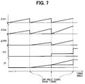
- FIG. 7 is a time chart for explaining the actual valve timing calculation according to the first embodiment.
- FIG. 8 is a time chart for explaining a way of an actual valve timing calculation according to a second embodiment.
- FIGS. 1 to 7 a first embodiment will be described hereinafter.
- FIG. 1 schematically shows a whole structure of an engine control system.
- An internal combustion engine 11 which is referred to as an engine hereinafter, includes a crankshaft 12 .
- a driving force of the crankshaft 12 is transmitted to an intake camshaft 16 and an exhaust camshaft 17 through a timing chain 13 (or a timing belt) and sprockets 14 , 15 .
- a variable valve timing controller 18 is coupled to the intake cam shaft 16 .
- the variable valve timing controller 18 varies a rotational phase (camshaft phase) of the intake camshaft 16 relative to the crankshaft 12 SO that the valve timing of an intake valve (not shown) is adjusted.
- a cam angle sensor 19 is provided around the intake camshaft 16 .
- the cam angle sensor 19 outputs a cam angle signal every predetermined cam angle of the intake camshaft 16 .
- a crank angle sensor 20 is provided around the cranks shaft 12 . The crank angle sensor 20 outputs a crank angle signal every predetermined crank angle.
- the variable valve timing controller 18 includes a phase control mechanism 21 .
- the phase control mechanism 21 includes an outer gear 22 , an inner gear 23 , and a planet gear 24 .
- the outer gear 22 is concentrically arranged with the intake camshaft 16 and has inner teeth.
- the inner gear 23 is concentrically arranged with the outer gear 22 and has outer teeth.
- the planet gear 24 is arranged between the outer gear 22 and the inner gear 23 to be engaged with both gears 22 , 23 .
- the outer gear 22 rotates integrally with the sprocket 14 which rotates in synchronization with the crankshaft 12
- the inner gear 23 rotates integrally with the intake camshaft 16 .
- the planet gear 24 rotates around the inner gear 23 to transfer a rotation force from the outer gear 22 to the inner gear 23 .
- a rotational phase of the inner gear 23 relative to the outer gar 22 is adjusted by varying a revolution speed of the planet gear 24 relative to the rotation speed of the inner gear 23 .
- the engine 11 is provided with a motor 26 which varies the revolution speed of the planet gear 24 .
- a rotation shaft 27 of the motor 26 is concentrically arranged with the intake camshaft 16 , the outer gear 22 , and the inner gear 23 .
- a connecting shaft 28 connects the rotation shaft 27 with a supporting shaft 25 of the planet gear 24 .
- the motor 26 is provided with a motor position sensor which outputs a motor angle signal according to a rotational position of the motor 26 .
- the rotation shaft 27 rotates in synchronization with the intake camshaft 16 . That is, when the rotation speed RM of the motor 26 is consistent with the rotational speed RC of the intake camshaft 16 , and the revolution speed of the planet gear 24 is consistent with the rotational speed of the inner gear 23 , a difference between a rotational phase of the outer gear 22 and a rotational phase of the inner gear 23 is maintained as a current difference to maintain the valve timing as the current valve timing.
- the outputs of the sensors are inputted into an electronic control unit 30 , which is referred to as an ECU 30 hereinafter.
- the ECU 30 includes a microcomputer which executes engine control programs stored in a ROM (read only memory) to control a fuel injection and an ignition timing according to an engine driving condition.
- FIGS. 3 to 5 are flowcharts showing actual valve timing calculation programs.
- the actual valve timing VTC is calculated based on the cam angle signal and the crank angle signal every when the cam angle signal is outputted.
- a valve timing varying amount ⁇ VT is calculated based on a difference between a rotational speed information of the motor 26 and the rotational speed information of the intake camshaft 16 .
- the valve timing varying amount ⁇ VT is added to the actual valve timing VTC to obtain a final actual valve timing VT.
- the actual valve timing VT is calculated in a predetermined calculating period to enhance controllability of the variable valve timing controller.
- a motor angle signal outputted from the motor position sensor 29 is counted every when the motor 26 rotates a predetermined angle.
- a crank angle signal outputted from the crank angle senor 20 is also counted every when the crankshaft 12 rotates a predetermined crank angle.
- a variation amount ⁇ Cmo of the motor angle signal count value is used as the rotational speed information of the motor 26
- a variation amount ⁇ Ccr of the crank angle signal count value is used as the rotational speed information of the intake camshaft 16 .
- step 101 a determination is made as to whether the engine 11 is running based on the crank angle signal from the crank angle sensor 20 .
- step 101 the procedure proceeds to step 102 in which a determination is made as to whether the cam angle sensor 19 is normal according to a cam angle sensor malfunction detecting program.
- step 103 a determination is made as to whether the cam angle signal outputted from the cam angle sensor 19 is inputted.
- step 103 the procedure proceeds to step 104 in which an input time Tcam of the cam angle signal is stored in a memory (not shown) of the ECU 3 O, and then procedure proceeds to step 105 in which an input time Tcrk of the crank angle signal is stored in the memory.
- step 106 a time difference TVT of the cam angle signal relative to the crank angle signal is calculated based on a following equation.
- TVT T crk ⁇ T cam+ K
- K is a correction value to correct a difference in response between the cam angle sensor 19 and the crank angle sensor 20 .
- step 107 the rotational phase VTB of the cam angle signal relative to the crank angle signal based on a following equation.
- VTB TVT/T 120 ⁇ 120° C.
- T120 is a time period in which the crankshaft 12 rotated 120° CA which is calculated based on the output signal of the crank angle sensor 20 .
- step 108 a determination is made as to whether the valve timing is at a reference position.
- step 109 a current rotational phase VTB of the cam angle signal relative to the crank angle signal is learned as the reference rotational phase VTBK of the intake camshaft 16 relative to the crankshaft 12 .
- step 110 the procedure proceeds to step 110 .
- VTBK VTB
- step 108 When the answer is No in step 108 , the procedure proceeds to step 110 , skipping step 109 .
- step 110 the rotational phase VTC of the cam angle signal relative to the reference rotational phase VTBK is calculated based on the current rotational phase VTB of the cam angle signal.
- the rotational phase VTC of the cam angle signal is defined as the actual valve timing VTC at the time the cam angle signal is outputted.
- VTC VTB ⁇ VTBK
- steps 103 to 110 serve as a valve timing calculating means at the time the cam angle signal is outputted.
- the actual valve timing VTC is calculated every when the cam angle signal is inputted.
- step 111 both the valve timing varying amounts ⁇ VTH and ⁇ VTS are reset to “0” every when the actual valve timing VTC at the time the cam angle signal is outputted is calculated.
- step 103 a determination is made as to whether the periodical actual valve timing calculating condition is established in steps 112 to 114 in FIG. 4 .
- the periodical actual valve timing calculating condition includes following conditions.
- a variation amount ⁇ NE of the engine speed NE per a predetermined period is more than or equal to a predetermined value ⁇ (step 112 ).
- a variation amount ⁇ VT of the actual valve timing VT per a predetermined period is more than or equal to a predetermined value ⁇ (step 113 ).
- a variation amount ⁇ VTtg of the target valve timing VTtg per a predetermined period is more than or equal to a predetermined value ⁇ (step 114 ).
- the periodical actual valve timing calculating condition is established.
- the procedure ends without executing steps 115 and following steps.
- step 115 the count value of the crank angle signal (or the count value of the motor angle signal) is corrected.
- step 116 a variation amount ⁇ Ccr of the crank angle signal count number, which is data having a correlation with a rotational angle varying amount of the intake camshaft 16 , based on the following equation.
- ⁇ C cr C cr( i ) ⁇ C cr( i ⁇ 1)
- Ccr (i) is a current count number of the crank angle signal
- Ccr (i ⁇ 1) is a previous count number of the crank angle signal
- step 117 a variation amount ⁇ Cmo of the motor angle signal count number, which is data having a correlation with a rotational angle varying amount of the motor 26 , based on the following equation.
- ⁇ C mo Cmo( i ) ⁇ C mo( i ⁇ 1)
- Cmo (i) is a current count number of the motor angle signal
- Cmo (i ⁇ 1) is a previous count number of the motor angle signal
- D 0 is a conversion coefficient, which corresponds to a rotational angle varying amount of the motor 26 relative to the intake camshaft 16 when the difference “C” is one count.
- G is a reduction ratio of the phase adjusting mechanism 21 , which corresponds to a ratio between a relative rotation amount of the motor 26 relative to the intake camshaft 16 and the valve timing varying amount (varying amount of the camshaft phase).
- step 121 the variable valve timing varying amount dVTH is integrated to drive the valve timing varying amount ⁇ VTH after an updated cam angle signal is outputted.
- ⁇ VTH ⁇ VTH+dVTH
- step 102 the procedure in steps 115 to 121 are performed to integrate the valve timing varying amount dVTH per one calculation period to derive the valve timing varying amount ⁇ VTH during a period from the time the cam angle sensor 19 is still normal to the time final cam angle signal is outputted before the cam angle sensor becomes faulty.
- VT VTC+ ⁇ VTH+ ⁇ VTS
- step 101 the computer determines the engine 11 is not running, the procedure proceeds to step 122 in which a variation amount ⁇ Cmo of count value of the motor angle signal according to a following equation.
- ⁇ C mo C mo( i ) ⁇ C mo( i ⁇ 1)
- step 123 the variation amount ⁇ Cmo is converted into the rotational angle varying amount D of the motor 26 based on the following equation.
- D C ⁇ D 0
- step 125 the valve timing varying amount dVTS is integrated to drive the valve timing varying amount ⁇ VTS during a period from the time when the final cam angle signal outputted before the engine stops until present time.
- ⁇ VTS ⁇ VTS+dVTS
- the actual valve timing may be calculated based on a mechanical reference position such as the most retarded position or a reference position detected by another detecting means.
- the driving condition is a predetermined condition
- the actual valve timing calculation at the time the cam angle is outputted is executed, and the periodical actual valve timing calculation is executed based on the rotational information of the motor 26 and the intake camshaft 16 . That is, when the variation amount ⁇ NE of the engine speed NE per a predetermined period is larger than a preset value as shown by an arrow “A” in FIG. 6A , when the variation amount ⁇ VT of the actual valve timing VT is larger than a preset value as shown by an arrow “A” in FIG. 6B , or when the variation amount ⁇ VTtg of the target valve timing VTtg is larger than a preset value as shown by an arrow “A” in FIG. 6C , the above calculation is executed.
- the actual valve timing VTC is calculated based on the cam angle signal and the crank angle signal every when the cam angle signal is inputted while the engine is running.
- the cam angle signal is inputted (outputted)
- the actual valve timing VTC at the time of cam angle signal outputting becomes the final actual valve timing VT.
- the cam angle signal is not inputted
- the valve timing varying amount dVTH is integrated to derive the valve timing varying amount ⁇ VTH.
- the valve timing varying amount ⁇ VTH is added to the updated actual valve timing VTC in order to derive the final actual valve timing VT.
- the periodical actual valve timing calculation is performed, so that the actual valve timing VT can be calculated in a predetermined time period to enhance the controllability of the variable valve timing controller.
- the actual valve timing calculation at the time of the cam angle signal is outputted is conducted to reduce the calculating load of the ECU 30 .
- a calculation period of each control program increases to reduce the calculation amount per a predetermined period.
- the periodical valve timing calculation is conducted to restrict the calculation load of the ECU 30 , and when the cam angle signal is not outputted, the actual valve timing is calculated in a predetermined time period to enhance the accuracy of the variable valve timing control.
- the valve timing varying amount ⁇ VT is calculated based on the count value of the motor angle signal and the crank angle signal.
- the valve timing varying amount ⁇ VT may be calculated based on a difference between the variation amount of the motor angle signal and the variation amount of the crank angle signal.
- the valve timing varying amount ⁇ VT may be calculated based on a difference between the rotational speed of the motor 26 and the rotational speed of the intake camshaft 16 .
- the phase adjust mechanism of the variable valve timing controller is not limited to the planetary gear mechanism.
Landscapes
- Engineering & Computer Science (AREA)
- Mechanical Engineering (AREA)
- General Engineering & Computer Science (AREA)
- Output Control And Ontrol Of Special Type Engine (AREA)
- Combined Controls Of Internal Combustion Engines (AREA)
Abstract
Description
TVT=Tcrk−Tcam+K
VTB=TVT/T120×120° C.A
VTBK=VTB
VTC=VTB−VTBK
VT=VTC+ΔVTH+ΔVTS
ΔCcr=Ccr(i)−Ccr(i−1)
ΔCmo=Cmo(i)−Cmo(i−1)
C=ΔCmo−ΔCcr
D=C×
dVTH=D/G
ΔVTH=ΔVTH+dVTH
VT=VTC+ΔVTH+ΔVTS
ΔCmo=Cmo(i)−Cmo(i−1)
D=C×
dVTS=D/G
ΔVTS=ΔVTS+dVTS
VT=VTC+ΔVTH+ΔVTS
Claims (1)
Applications Claiming Priority (2)
| Application Number | Priority Date | Filing Date | Title |
|---|---|---|---|
| JP2004-253176 | 2004-08-31 | ||
| JP2004253176A JP4196294B2 (en) | 2004-08-31 | 2004-08-31 | Variable valve timing control device for internal combustion engine |
Publications (2)
| Publication Number | Publication Date |
|---|---|
| US20060042579A1 US20060042579A1 (en) | 2006-03-02 |
| US7308877B2 true US7308877B2 (en) | 2007-12-18 |
Family
ID=35941260
Family Applications (1)
| Application Number | Title | Priority Date | Filing Date |
|---|---|---|---|
| US11/213,900 Expired - Lifetime US7308877B2 (en) | 2004-08-31 | 2005-08-30 | Variable valve timing controller for internal combustion engine |
Country Status (3)
| Country | Link |
|---|---|
| US (1) | US7308877B2 (en) |
| JP (1) | JP4196294B2 (en) |
| DE (1) | DE102005041092B4 (en) |
Cited By (5)
| Publication number | Priority date | Publication date | Assignee | Title |
|---|---|---|---|---|
| US20070227483A1 (en) * | 2006-03-30 | 2007-10-04 | Toyota Jidosha Kabushiki Kaisha | Variable valve timing apparatus executing reference position learning and control method thereof |
| US20080065308A1 (en) * | 2006-08-30 | 2008-03-13 | Denso Corporation | Variable valve timing controller for internal combustion engine |
| US20090101108A1 (en) * | 2007-10-17 | 2009-04-23 | Horst Wagner | Method and device for monitoring control and regulating loops in an engine system |
| US20090288621A1 (en) * | 2008-05-26 | 2009-11-26 | Hitachi, Ltd. | Apparatus For and Method of Controlling Variable Valve Timing Mechanism |
| US7685994B2 (en) | 2006-03-27 | 2010-03-30 | Toyota Jidosha Kabushiki Kaisha | Variable valve timing apparatus and method of detecting valve phase thereof |
Families Citing this family (20)
| Publication number | Priority date | Publication date | Assignee | Title |
|---|---|---|---|---|
| JP4269169B2 (en) * | 2004-08-31 | 2009-05-27 | 株式会社デンソー | Rotational state detection device for internal combustion engine |
| JP2006112385A (en) * | 2004-10-18 | 2006-04-27 | Denso Corp | Variable valve timing control device for internal combustion engine |
| JP4600326B2 (en) * | 2006-03-27 | 2010-12-15 | トヨタ自動車株式会社 | Variable valve timing device |
| GB2440167B (en) * | 2006-07-12 | 2008-09-10 | Denso Corp | Variable valve timing control |
| JP4641986B2 (en) * | 2006-08-30 | 2011-03-02 | 株式会社デンソー | Variable valve timing control device for internal combustion engine |
| JP4641985B2 (en) | 2006-08-30 | 2011-03-02 | 株式会社デンソー | Variable valve timing control device for internal combustion engine |
| JP4600935B2 (en) * | 2006-08-30 | 2010-12-22 | 株式会社デンソー | Variable valve timing control device for internal combustion engine |
| JP4668150B2 (en) * | 2006-08-31 | 2011-04-13 | トヨタ自動車株式会社 | Variable valve timing device |
| JP4591842B2 (en) | 2007-04-17 | 2010-12-01 | 株式会社デンソー | Control device for electric variable valve timing device |
| JP2009257186A (en) * | 2008-04-16 | 2009-11-05 | Denso Corp | Control device for variable valve timing apparatus |
| JP6266364B2 (en) | 2014-01-30 | 2018-01-24 | 日立オートモティブシステムズ株式会社 | Control device for internal combustion engine |
| JP6406091B2 (en) * | 2015-03-27 | 2018-10-17 | 株式会社デンソー | Variable valve system |
| DE102015219335B3 (en) * | 2015-10-07 | 2017-02-02 | Continental Automotive Gmbh | Method for controlling an internal combustion engine with a camshaft |
| DE102018102880A1 (en) * | 2017-02-16 | 2018-08-16 | Borgwarner Inc. | Method for start-up control of an electric camshaft adjuster |
| JP6716477B2 (en) * | 2017-02-16 | 2020-07-01 | 日立オートモティブシステムズ株式会社 | Control device and control method for variable valve timing device |
| JP6689778B2 (en) * | 2017-03-22 | 2020-04-28 | 日立オートモティブシステムズ株式会社 | Control device and control method for variable valve timing device |
| JP6800831B2 (en) | 2017-11-29 | 2020-12-16 | 日立オートモティブシステムズ株式会社 | Variable valve control device, variable valve control system, and control method of variable valve mechanism |
| JP2021011820A (en) * | 2019-07-03 | 2021-02-04 | 日立オートモティブシステムズ株式会社 | Control device of variable valve timing mechanism and method of controlling the same |
| CN115199416B (en) * | 2022-07-21 | 2023-07-18 | 无锡威孚高科技集团股份有限公司 | Engine variable valve timing control method and control system |
| CN115450724A (en) * | 2022-10-17 | 2022-12-09 | 杰锋汽车动力系统股份有限公司 | Electric variable valve timing closed-loop control system and control method thereof |
Citations (5)
| Publication number | Priority date | Publication date | Assignee | Title |
|---|---|---|---|---|
| US3978829A (en) * | 1974-06-10 | 1976-09-07 | Nissan Motor Co., Ltd. | Self-adjustable camshaft drive mechanism |
| US6405694B2 (en) | 2000-06-09 | 2002-06-18 | Denso Corporation | Variable valve timing control device for internal combustion engine |
| US7059285B2 (en) * | 2002-07-11 | 2006-06-13 | Ina-Schaeffler Kg | Control structure for the adjusting motor of an electric camshaft adjuster |
| US7077087B2 (en) * | 2004-04-23 | 2006-07-18 | Denso Corporation | Valve timing controller |
| US7107951B2 (en) * | 2002-10-25 | 2006-09-19 | Denso Corporation | Variable valve timing control device of internal combustion engine |
Family Cites Families (1)
| Publication number | Priority date | Publication date | Assignee | Title |
|---|---|---|---|---|
| JP4123127B2 (en) | 2002-10-25 | 2008-07-23 | 株式会社デンソー | Variable valve timing control device for internal combustion engine |
-
2004
- 2004-08-31 JP JP2004253176A patent/JP4196294B2/en not_active Expired - Lifetime
-
2005
- 2005-08-30 US US11/213,900 patent/US7308877B2/en not_active Expired - Lifetime
- 2005-08-30 DE DE102005041092.8A patent/DE102005041092B4/en not_active Expired - Lifetime
Patent Citations (6)
| Publication number | Priority date | Publication date | Assignee | Title |
|---|---|---|---|---|
| US3978829A (en) * | 1974-06-10 | 1976-09-07 | Nissan Motor Co., Ltd. | Self-adjustable camshaft drive mechanism |
| US6405694B2 (en) | 2000-06-09 | 2002-06-18 | Denso Corporation | Variable valve timing control device for internal combustion engine |
| US7059285B2 (en) * | 2002-07-11 | 2006-06-13 | Ina-Schaeffler Kg | Control structure for the adjusting motor of an electric camshaft adjuster |
| US20060124095A1 (en) * | 2002-07-11 | 2006-06-15 | Ina-Schaeffler Kg | Control structure for the adjusting motor of an electric camshaft adjuster |
| US7107951B2 (en) * | 2002-10-25 | 2006-09-19 | Denso Corporation | Variable valve timing control device of internal combustion engine |
| US7077087B2 (en) * | 2004-04-23 | 2006-07-18 | Denso Corporation | Valve timing controller |
Non-Patent Citations (1)
| Title |
|---|
| U.S. Appl. No. 10/510,765, filed Oct. 23, 2003 in the name of Urushihata et al for Variable Valve Timing Control Device of Internal Combustion Engine. |
Cited By (9)
| Publication number | Priority date | Publication date | Assignee | Title |
|---|---|---|---|---|
| US7685994B2 (en) | 2006-03-27 | 2010-03-30 | Toyota Jidosha Kabushiki Kaisha | Variable valve timing apparatus and method of detecting valve phase thereof |
| US20070227483A1 (en) * | 2006-03-30 | 2007-10-04 | Toyota Jidosha Kabushiki Kaisha | Variable valve timing apparatus executing reference position learning and control method thereof |
| US7360516B2 (en) * | 2006-03-30 | 2008-04-22 | Toyota Jidosha Kabushiki Kaisha | Variable valve timing apparatus executing reference position learning and control method thereof |
| US20080065308A1 (en) * | 2006-08-30 | 2008-03-13 | Denso Corporation | Variable valve timing controller for internal combustion engine |
| US7412323B2 (en) * | 2006-08-30 | 2008-08-12 | Denso Corporation | Variable valve timing controller for internal combustion engine |
| US20090101108A1 (en) * | 2007-10-17 | 2009-04-23 | Horst Wagner | Method and device for monitoring control and regulating loops in an engine system |
| US8245689B2 (en) * | 2007-10-17 | 2012-08-21 | Robert Bosch Gmbh | Method and device for monitoring control and regulating loops in an engine system |
| US20090288621A1 (en) * | 2008-05-26 | 2009-11-26 | Hitachi, Ltd. | Apparatus For and Method of Controlling Variable Valve Timing Mechanism |
| US8091523B2 (en) * | 2008-05-26 | 2012-01-10 | Hitachi, Ltd. | Apparatus for and method of controlling variable valve timing mechanism |
Also Published As
| Publication number | Publication date |
|---|---|
| US20060042579A1 (en) | 2006-03-02 |
| JP2006070754A (en) | 2006-03-16 |
| DE102005041092B4 (en) | 2023-08-10 |
| JP4196294B2 (en) | 2008-12-17 |
| DE102005041092A1 (en) | 2006-04-06 |
Similar Documents
| Publication | Publication Date | Title |
|---|---|---|
| US7308877B2 (en) | Variable valve timing controller for internal combustion engine | |
| US7584729B2 (en) | Variable valve timing controller for internal combustion engine | |
| US7412323B2 (en) | Variable valve timing controller for internal combustion engine | |
| US7762222B2 (en) | Variable valve timing controller for internal combustion engine | |
| JP4123127B2 (en) | Variable valve timing control device for internal combustion engine | |
| US7363896B2 (en) | Variable valve timing control device of internal combustion engine | |
| EP2035661B1 (en) | Variable valve timing apparatus and control method thereof | |
| JPH07269380A (en) | Valve timing controller of internal combustion engine | |
| US8051831B2 (en) | Control device for variable valve timing apparatus | |
| US7489999B2 (en) | Control apparatus and control method for variable valve apparatus | |
| JP2006220077A (en) | Control device for variable valve mechanism | |
| JPH10227235A (en) | Valve timing control device for internal combustion engine | |
| JP3395240B2 (en) | Valve timing control device for internal combustion engine | |
| JP5015710B2 (en) | Intake air amount control device for internal combustion engine | |
| EP2222940B1 (en) | Non-synchronous belt driven camshaft phase shift device | |
| US6341586B2 (en) | Valve timing control system for internal combustion engine | |
| JP4013274B2 (en) | Valve timing control device for internal combustion engine | |
| JPH1182073A (en) | Variable valve timing control device for internal combustion engine | |
| JP4039270B2 (en) | Valve timing control device for internal combustion engine | |
| JP3666483B2 (en) | Valve timing control device for internal combustion engine | |
| JP3711977B2 (en) | Valve timing control device for internal combustion engine | |
| JP3666482B2 (en) | Valve timing control device for internal combustion engine | |
| JPH04321748A (en) | Variable valve timing control apparatus | |
| JP3918219B2 (en) | Valve timing control device for internal combustion engine | |
| JP2005291141A (en) | Reference position learning device for variable valve device |
Legal Events
| Date | Code | Title | Description |
|---|---|---|---|
| AS | Assignment |
Owner name: DENSO CORPORATION, JAPAN Free format text: ASSIGNMENT OF ASSIGNORS INTEREST;ASSIGNORS:IZUMI, KAZUNARI;URUSHIHATA, HARUYUKI;REEL/FRAME:016929/0551 Effective date: 20050816 |
|
| STCF | Information on status: patent grant |
Free format text: PATENTED CASE |
|
| FPAY | Fee payment |
Year of fee payment: 4 |
|
| FEPP | Fee payment procedure |
Free format text: PAYOR NUMBER ASSIGNED (ORIGINAL EVENT CODE: ASPN); ENTITY STATUS OF PATENT OWNER: LARGE ENTITY |
|
| FPAY | Fee payment |
Year of fee payment: 8 |
|
| MAFP | Maintenance fee payment |
Free format text: PAYMENT OF MAINTENANCE FEE, 12TH YEAR, LARGE ENTITY (ORIGINAL EVENT CODE: M1553); ENTITY STATUS OF PATENT OWNER: LARGE ENTITY Year of fee payment: 12 |