US7288744B2 - Injector for equipment for injection moulding of plastic materials - Google Patents
Injector for equipment for injection moulding of plastic materials Download PDFInfo
- Publication number
- US7288744B2 US7288744B2 US11/236,443 US23644305A US7288744B2 US 7288744 B2 US7288744 B2 US 7288744B2 US 23644305 A US23644305 A US 23644305A US 7288744 B2 US7288744 B2 US 7288744B2
- Authority
- US
- United States
- Prior art keywords
- resistor
- injector
- area
- thermocouple
- wound
- Prior art date
- Legal status (The legal status is an assumption and is not a legal conclusion. Google has not performed a legal analysis and makes no representation as to the accuracy of the status listed.)
- Expired - Fee Related, expires
Links
- 238000001746 injection moulding Methods 0.000 title claims abstract description 4
- 239000000463 material Substances 0.000 title claims abstract description 4
- 238000010438 heat treatment Methods 0.000 claims abstract description 18
- 239000004020 conductor Substances 0.000 description 4
- 230000004048 modification Effects 0.000 description 3
- 238000012986 modification Methods 0.000 description 3
- 239000000243 solution Substances 0.000 description 3
- 238000003754 machining Methods 0.000 description 2
- 238000000034 method Methods 0.000 description 2
- 230000004323 axial length Effects 0.000 description 1
- 238000010276 construction Methods 0.000 description 1
- 230000017525 heat dissipation Effects 0.000 description 1
Images


Classifications
-
- B—PERFORMING OPERATIONS; TRANSPORTING
- B29—WORKING OF PLASTICS; WORKING OF SUBSTANCES IN A PLASTIC STATE IN GENERAL
- B29C—SHAPING OR JOINING OF PLASTICS; SHAPING OF MATERIAL IN A PLASTIC STATE, NOT OTHERWISE PROVIDED FOR; AFTER-TREATMENT OF THE SHAPED PRODUCTS, e.g. REPAIRING
- B29C45/00—Injection moulding, i.e. forcing the required volume of moulding material through a nozzle into a closed mould; Apparatus therefor
- B29C45/17—Component parts, details or accessories; Auxiliary operations
- B29C45/26—Moulds
- B29C45/27—Sprue channels ; Runner channels or runner nozzles
- B29C45/2737—Heating or cooling means therefor
- B29C2045/2754—Plurality of independent heating or cooling means, e.g. independently controlling the heating of several zones of the nozzle
Definitions
- the present invention relates in general to equipment for injection moulding of plastic materials, and regards, more in particular, an injector for said equipment, of the type comprising a generally cylindrical body wound on which are electrical resistor means for heating associated to which are thermocouple control means.
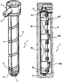
- FIG. 1 of the annexed plate of drawings illustrates an injector of this sort according to the known art, produced and marketed for some time by the present applicant.
- the generally cylindrical body 1 of the injector extends between a head end 2 and a tip end 3 and has a generally helical outer groove 4 , housed within which is an electrical heating resistor 5 , the control thermocouple of which, located in the position designated by 6 , is set in the proximity of the tip end 3 .
- the groove 4 can house a pair of resistors set alongside one another (or even on top of one another) independent of one another, in conformance with what is described and illustrated in the European patent No. EP-B-1252998.
- the heating resistor 5 or each heating resistor 5 is wound along the entire the axial extension of the body 1 between the head end 2 and the tip end 3 and is supplied in a way in itself known via electrical conductors (not illustrated) that traverse a radial tubular appendage 7 projecting from the head end 2 .
- thermocouples 5 In the case where two resistors 5 are provided, associated to each of them will be a respective independent thermocouple, and both of the thermocouples will be positioned in the same area designated by 6 .
- the resistor or resistors 5 heat the body 1 of the injector in a homogeneous way throughout its axial extension.
- the axial dimension of the body 1 can even be considerable, a fact that involves heating the area corresponding to the tip end 3 independently of the central area of the body 1 .
- the central area instead, which not only is not in direct contact with the mould but rather is normally surrounded by an air gap that insulates it, tends instead to accumulate heat.
- FIG. 2 of the annexed plate of drawings is a schematic illustration of the cross-sectional shape of the seat of the mould within which the body 1 of the injector is housed. As may be seen, said shape is simply circular.
- the object of the present invention is to solve the technical problem defined at the beginning of the present description, overcoming the drawbacks of the known art outlined above.
- this object is achieved thanks to the fact that in an injector of the type specified above, in which the aforesaid resistor means include at least one first resistor for heating a first area of the body and at least one second resistor for heating a second area of the body, the aforesaid first area of the body of the injector on which said at least one first resistor is wound extends substantially along the entire axial extension of the body, and said second area on which said at least one second resistor is wound extends only along an axial portion of the body of the injector.
- Said second axial portion along which the aforesaid at least one second resistor is wound is normally comprised between the head end and a substantially intermediate area of the body at a distance from its tip end.
- the control thermocouple associated to the aforesaid at least one second resistor is positioned in an area corresponding to said substantially intermediate area of the body, whilst the control thermocouple of the aforesaid at least one first resistor will normally be located in the proximity of the tip end of the body of the injector.
- the electrical conductors for supply of the heating resistors and of the corresponding thermocouples can come under the head end of the body of the injector, with the advantage of not entailing modifications of the seat of the mould within which the injector is housed, said seat not requiring any supplementary machining operations and rather corresponding in shape and size to the existing seats for the conventional injectors illustrated previously with reference to FIGS. 1 and 2 . Consequently, the injector according to the invention can directly and immediately replace existing injectors on moulds that are already operative.
- FIG. 2 is a schematic illustration of the cross section of the seat of the mould for housing the injector of FIG. 1 ;
- FIG. 3 is a schematic elevation of an injector according to a second known technique
- FIG. 5 is a view similar to that of FIG. 1 that shows an injector according to the invention.
- FIG. 6 is a view similar to those of FIGS. 2 and 4 , which shows the seat of the mould for housing the injector according to FIG. 5 .
- a first electrical heating resistor 5 (or a pair of first resistors set alongside one another or on top of one another) is inserted within a variable-pitch helical groove 4 , which extends for the entire axial length of the body 1 , between the head end 2 and the tip end 3 , and is controlled by the thermocouple set in the position designated by 6 , i.e., adjacent to said tip end 3 .
- a second heating resistor 11 (or a pair of second heating resistors set alongside or on top of one another), independent of the first resistor 5 , is housed within a second helical groove 12 of the body 1 and extends only along an axial portion thereof, comprised between the head end 2 and a substantially intermediate area set at a distance from the tip end 3 .
- the second heating resistor 11 is controlled by an autonomous thermocouple 13 set in a position corresponding to said intermediate area of the body 1 .
- the area of the tip end 3 can be heated by the first resistor 5 independently of the central area of the body 1 .
- the electrical conductors for supply both of the resistor or resistors 5 and of the resistor or resistors 11 , as well as of the corresponding control thermocouples 6 and 13 can all come under the lateral appendage 7 of the head end 2 , which does not entail radial projections along the extension of the body 1 (unlike what has been described with reference to the known art in FIG. 3 ), with the advantage of not requiring any modification of the seat of the mould for housing the injector, the cross section 8 of which, represented schematically in FIG. 6 , will have a circular shape and dimensions identical to those represented in FIG.
Abstract
Description
Claims (3)
Applications Claiming Priority (2)
| Application Number | Priority Date | Filing Date | Title |
|---|---|---|---|
| IT000717A ITTO20040717A1 (en) | 2004-10-15 | 2004-10-15 | INJECTOR FOR PLASTIC INJECTION MOLDING EQUIPMENT |
| ITTO2004A000717 | 2004-10-15 |
Publications (2)
| Publication Number | Publication Date |
|---|---|
| US20060081590A1 US20060081590A1 (en) | 2006-04-20 |
| US7288744B2 true US7288744B2 (en) | 2007-10-30 |
Family
ID=36129100
Family Applications (1)
| Application Number | Title | Priority Date | Filing Date |
|---|---|---|---|
| US11/236,443 Expired - Fee Related US7288744B2 (en) | 2004-10-15 | 2005-09-27 | Injector for equipment for injection moulding of plastic materials |
Country Status (3)
| Country | Link |
|---|---|
| US (1) | US7288744B2 (en) |
| DE (1) | DE102005044439A1 (en) |
| IT (1) | ITTO20040717A1 (en) |
Families Citing this family (1)
| Publication number | Priority date | Publication date | Assignee | Title |
|---|---|---|---|---|
| CN108889472A (en) * | 2018-08-01 | 2018-11-27 | 苏州睿璟精密模具有限公司 | New type nozzle |
Citations (11)
| Publication number | Priority date | Publication date | Assignee | Title |
|---|---|---|---|---|
| US4721847A (en) * | 1986-01-08 | 1988-01-26 | Fast Heat Element Mfg. Co., Inc. | Multiple zoned runner distributor heater |
| US4875845A (en) * | 1987-03-31 | 1989-10-24 | Sumitomo Heavy Industries, Ltd. | Injection nozzle for an injection molding machine |
| US5113576A (en) * | 1990-03-01 | 1992-05-19 | Eurotool B.V. | Process for the production of an injection nozzle for use in an injection molding device |
| US6104006A (en) * | 1996-07-17 | 2000-08-15 | Kabushiki Kaisha Meiki Seisakusho | Method and apparatus for the programmed temperature control of a heating barrel |
| US6323465B1 (en) * | 1998-01-13 | 2001-11-27 | Mold-Masters Limited | Externally heated hot-runner nozzle with resistance wire |
| EP1252998A2 (en) * | 2001-04-27 | 2002-10-30 | Quaser S.r.L | Nozzle for injection moulding of plastic materials |
| US6495804B2 (en) * | 2000-03-07 | 2002-12-17 | Theysohn Extrusionstechnik Gesellschaft M.B.H. | Method of and system for heating and cooling an extruder cylinder |
| US20030228390A1 (en) * | 2000-03-08 | 2003-12-11 | Mold-Masters Limited | Compact cartridge hot runner nozzle and method of making |
| US20040091566A1 (en) * | 2002-11-06 | 2004-05-13 | Mold-Masters Limited | Injection nozzle with planar heater |
| US20050104242A1 (en) * | 2002-11-06 | 2005-05-19 | Mold-Masters Limited | Injection nozzle with a removable heater device having one or more heating elements |
| US7071449B2 (en) * | 1998-06-12 | 2006-07-04 | Husky Injection Molding Systems Ltd. | Molding system with integrated film heaters and sensors |
-
2004
- 2004-10-15 IT IT000717A patent/ITTO20040717A1/en unknown
-
2005
- 2005-09-16 DE DE102005044439A patent/DE102005044439A1/en not_active Withdrawn
- 2005-09-27 US US11/236,443 patent/US7288744B2/en not_active Expired - Fee Related
Patent Citations (12)
| Publication number | Priority date | Publication date | Assignee | Title |
|---|---|---|---|---|
| US4721847A (en) * | 1986-01-08 | 1988-01-26 | Fast Heat Element Mfg. Co., Inc. | Multiple zoned runner distributor heater |
| US4875845A (en) * | 1987-03-31 | 1989-10-24 | Sumitomo Heavy Industries, Ltd. | Injection nozzle for an injection molding machine |
| US5113576A (en) * | 1990-03-01 | 1992-05-19 | Eurotool B.V. | Process for the production of an injection nozzle for use in an injection molding device |
| US6104006A (en) * | 1996-07-17 | 2000-08-15 | Kabushiki Kaisha Meiki Seisakusho | Method and apparatus for the programmed temperature control of a heating barrel |
| US6323465B1 (en) * | 1998-01-13 | 2001-11-27 | Mold-Masters Limited | Externally heated hot-runner nozzle with resistance wire |
| US7071449B2 (en) * | 1998-06-12 | 2006-07-04 | Husky Injection Molding Systems Ltd. | Molding system with integrated film heaters and sensors |
| US6495804B2 (en) * | 2000-03-07 | 2002-12-17 | Theysohn Extrusionstechnik Gesellschaft M.B.H. | Method of and system for heating and cooling an extruder cylinder |
| US20030228390A1 (en) * | 2000-03-08 | 2003-12-11 | Mold-Masters Limited | Compact cartridge hot runner nozzle and method of making |
| EP1252998A2 (en) * | 2001-04-27 | 2002-10-30 | Quaser S.r.L | Nozzle for injection moulding of plastic materials |
| US20020160075A1 (en) * | 2001-04-27 | 2002-10-31 | A.S. Attrezzature Special | Nozzle for injection moulding of plastic materials |
| US20040091566A1 (en) * | 2002-11-06 | 2004-05-13 | Mold-Masters Limited | Injection nozzle with planar heater |
| US20050104242A1 (en) * | 2002-11-06 | 2005-05-19 | Mold-Masters Limited | Injection nozzle with a removable heater device having one or more heating elements |
Non-Patent Citations (1)
| Title |
|---|
| U.S. Appl. No. 11/176,408, filed Jul. 7, 2005, Bazzo et al. |
Also Published As
| Publication number | Publication date |
|---|---|
| ITTO20040717A1 (en) | 2005-01-15 |
| US20060081590A1 (en) | 2006-04-20 |
| DE102005044439A1 (en) | 2006-04-27 |
Similar Documents
| Publication | Publication Date | Title |
|---|---|---|
| US7210921B2 (en) | Nozzle for injection moulding of plastic materials | |
| US6305923B1 (en) | Molding system using film heaters and/or sensors | |
| US7367796B2 (en) | Heating cylinder for attachment to an injection nozzle for an injection molding system | |
| US4875845A (en) | Injection nozzle for an injection molding machine | |
| US7288744B2 (en) | Injector for equipment for injection moulding of plastic materials | |
| WO2006123237A2 (en) | Injector-nozzle tip for equipment for injection moulding of plastic materials | |
| US20060018990A1 (en) | Injector for equipment for injection moulding of plastic materials | |
| KR960007145A (en) | Hot runner probe and its device | |
| US20090022842A1 (en) | Injector for injection-moulding of plastic materials | |
| KR20100040268A (en) | An acute nozzle device for a hot runner probe | |
| US20120181728A1 (en) | Injection molding nozzle | |
| CA2555897C (en) | Heating cylinder for attachment to an injection nozzle for an injection molding system | |
| KR101353362B1 (en) | Heating cylinder for attachment to an injection nozzle for an injection molding system | |
| JP2001041331A (en) | Spool valve | |
| AU2006203438B2 (en) | Heating cylinder for attachment to an injection nozzle for an injection molding system | |
| JP7442159B2 (en) | Injection nozzle and nozzle heater | |
| JPS6337228Y2 (en) | ||
| JPH0985794A (en) | Device for controlling temperature of injection nozzle | |
| EP2495083B1 (en) | Injector for equipment for injection moduling of plastic materials | |
| JP2008037084A (en) | Heating cylinder attached to injection nozzle for injection molding system | |
| JP2003211493A (en) | Gate nozzle for mold for injection molding | |
| JP5523515B2 (en) | Heating cylinder attached to injection nozzle for injection molding system | |
| JPS63154210U (en) | ||
| JPH0460808B2 (en) | ||
| MXPA06009277A (en) | Heating cylinder for attachment to an injection nozzle molding system. |
Legal Events
| Date | Code | Title | Description |
|---|---|---|---|
| AS | Assignment |
Owner name: INCOS S.P.A., ITALY Free format text: ASSIGNMENT OF ASSIGNORS INTEREST;ASSIGNORS:DAL BO, PETER;TREVISIOL, NICO;REEL/FRAME:017040/0996 Effective date: 20050915 |
|
| AS | Assignment |
Owner name: INGLASS S.P.A.,ITALY Free format text: CHANGE OF NAME;ASSIGNOR:INCOS S.P.A.;REEL/FRAME:018184/0627 Effective date: 20060530 Owner name: INGLASS S.P.A., ITALY Free format text: CHANGE OF NAME;ASSIGNOR:INCOS S.P.A.;REEL/FRAME:018184/0627 Effective date: 20060530 |
|
| AS | Assignment |
Owner name: INGLASS S.R.L., ITALY Free format text: ASSIGNMENT OF ASSIGNORS INTEREST;ASSIGNOR:INGLASS S.P.A.;REEL/FRAME:023401/0399 Effective date: 20090915 Owner name: INGLASS S.R.L.,ITALY Free format text: ASSIGNMENT OF ASSIGNORS INTEREST;ASSIGNOR:INGLASS S.P.A.;REEL/FRAME:023401/0399 Effective date: 20090915 |
|
| REMI | Maintenance fee reminder mailed | ||
| LAPS | Lapse for failure to pay maintenance fees | ||
| STCH | Information on status: patent discontinuation |
Free format text: PATENT EXPIRED DUE TO NONPAYMENT OF MAINTENANCE FEES UNDER 37 CFR 1.362 |
|
| FP | Lapsed due to failure to pay maintenance fee |
Effective date: 20111030 |