US7281622B2 - Conveyor system for high speed, high performance bagger - Google Patents
Conveyor system for high speed, high performance bagger Download PDFInfo
- Publication number
- US7281622B2 US7281622B2 US11/364,221 US36422106A US7281622B2 US 7281622 B2 US7281622 B2 US 7281622B2 US 36422106 A US36422106 A US 36422106A US 7281622 B2 US7281622 B2 US 7281622B2
- Authority
- US
- United States
- Prior art keywords
- belts
- conveyor
- assembly
- returning
- advancing
- Prior art date
- Legal status (The legal status is an assumption and is not a legal conclusion. Google has not performed a legal analysis and makes no representation as to the accuracy of the status listed.)
- Expired - Fee Related, expires
Links
Images


Classifications
-
- B—PERFORMING OPERATIONS; TRANSPORTING
- B65—CONVEYING; PACKING; STORING; HANDLING THIN OR FILAMENTARY MATERIAL
- B65G—TRANSPORT OR STORAGE DEVICES, e.g. CONVEYORS FOR LOADING OR TIPPING, SHOP CONVEYOR SYSTEMS OR PNEUMATIC TUBE CONVEYORS
- B65G57/00—Stacking of articles
- B65G57/32—Stacking of articles characterised by stacking during transit
-
- B—PERFORMING OPERATIONS; TRANSPORTING
- B65—CONVEYING; PACKING; STORING; HANDLING THIN OR FILAMENTARY MATERIAL
- B65B—MACHINES, APPARATUS OR DEVICES FOR, OR METHODS OF, PACKAGING ARTICLES OR MATERIALS; UNPACKING
- B65B63/00—Auxiliary devices, not otherwise provided for, for operating on articles or materials to be packaged
- B65B63/02—Auxiliary devices, not otherwise provided for, for operating on articles or materials to be packaged for compressing or compacting articles or materials prior to wrapping or insertion in containers or receptacles
- B65B63/026—Auxiliary devices, not otherwise provided for, for operating on articles or materials to be packaged for compressing or compacting articles or materials prior to wrapping or insertion in containers or receptacles for compressing by feeding articles through a narrowing space
-
- B—PERFORMING OPERATIONS; TRANSPORTING
- B65—CONVEYING; PACKING; STORING; HANDLING THIN OR FILAMENTARY MATERIAL
- B65G—TRANSPORT OR STORAGE DEVICES, e.g. CONVEYORS FOR LOADING OR TIPPING, SHOP CONVEYOR SYSTEMS OR PNEUMATIC TUBE CONVEYORS
- B65G15/00—Conveyors having endless load-conveying surfaces, i.e. belts and like continuous members, to which tractive effort is transmitted by means other than endless driving elements of similar configuration
- B65G15/10—Conveyors having endless load-conveying surfaces, i.e. belts and like continuous members, to which tractive effort is transmitted by means other than endless driving elements of similar configuration comprising two or more co-operating endless surfaces with parallel longitudinal axes, or a multiplicity of parallel elements, e.g. ropes defining an endless surface
- B65G15/12—Conveyors having endless load-conveying surfaces, i.e. belts and like continuous members, to which tractive effort is transmitted by means other than endless driving elements of similar configuration comprising two or more co-operating endless surfaces with parallel longitudinal axes, or a multiplicity of parallel elements, e.g. ropes defining an endless surface with two or more endless belts
- B65G15/14—Conveyors having endless load-conveying surfaces, i.e. belts and like continuous members, to which tractive effort is transmitted by means other than endless driving elements of similar configuration comprising two or more co-operating endless surfaces with parallel longitudinal axes, or a multiplicity of parallel elements, e.g. ropes defining an endless surface with two or more endless belts the load being conveyed between the belts
-
- B—PERFORMING OPERATIONS; TRANSPORTING
- B65—CONVEYING; PACKING; STORING; HANDLING THIN OR FILAMENTARY MATERIAL
- B65G—TRANSPORT OR STORAGE DEVICES, e.g. CONVEYORS FOR LOADING OR TIPPING, SHOP CONVEYOR SYSTEMS OR PNEUMATIC TUBE CONVEYORS
- B65G47/00—Article or material-handling devices associated with conveyors; Methods employing such devices
- B65G47/52—Devices for transferring articles or materials between conveyors i.e. discharging or feeding devices
- B65G47/64—Switching conveyors
- B65G47/644—Switching conveyors by a pivoting displacement of the switching conveyor
- B65G47/645—Switching conveyors by a pivoting displacement of the switching conveyor about a horizontal axis
- B65G47/647—Switching conveyors by a pivoting displacement of the switching conveyor about a horizontal axis the axis being perpendicular to the conveying direction
-
- B—PERFORMING OPERATIONS; TRANSPORTING
- B65—CONVEYING; PACKING; STORING; HANDLING THIN OR FILAMENTARY MATERIAL
- B65G—TRANSPORT OR STORAGE DEVICES, e.g. CONVEYORS FOR LOADING OR TIPPING, SHOP CONVEYOR SYSTEMS OR PNEUMATIC TUBE CONVEYORS
- B65G47/00—Article or material-handling devices associated with conveyors; Methods employing such devices
- B65G47/52—Devices for transferring articles or materials between conveyors i.e. discharging or feeding devices
- B65G47/68—Devices for transferring articles or materials between conveyors i.e. discharging or feeding devices adapted to receive articles arriving in one layer from one conveyor lane and to transfer them in individual layers to more than one conveyor lane or to one broader conveyor lane, or vice versa, e.g. combining the flows of articles conveyed by more than one conveyor
- B65G47/71—Devices for transferring articles or materials between conveyors i.e. discharging or feeding devices adapted to receive articles arriving in one layer from one conveyor lane and to transfer them in individual layers to more than one conveyor lane or to one broader conveyor lane, or vice versa, e.g. combining the flows of articles conveyed by more than one conveyor the articles being discharged or distributed to several distinct separate conveyors or to a broader conveyor lane
Definitions
- the present invention relates to an apparatus and method for compressing and packaging compressible batts, and is useful, in particular, for the compression packaging of batts of insulating material.
- the batts once at least partially compressed, remain under compression without being allowed to expand during the compressing and packaging.
- Fibrous insulation material is typically manufactured in common lengths and widths, called insulation batts, to accommodate typical building frame structure dimensions.
- Fibrous insulation batts are commonly made of mineral fibers, such as glass fibers, and usually have a density within the range of from about 0.2 to about 1.0 pounds per cubic foot (3.2 to 16 kg/m 3 ). Typical batt sizes are 16 or 24 inches (40.6 cm or 61.0 cm) wide by 8 to 10 feet (2.44 m) long. These batts can be packaged in various ways. The batts can be staggered and rolled together along their lengths so that a roll would contain about 10 batts.
- the compression of the insulation batts has been achieved by stacking the batts in a compression chamber which has a fork for compressing the batts and a piston for discharging the compressed batts from the compression chamber into a bagging apparatus.
- the compressed batts are typically forced into the bag.
- the insulation batts are delivered to the compression machine by an endless conveyor from a production line. To avoid interruption of the operation of the production line or an accumulation of uncompressed insulation batts, it is necessary to ensure that the insulation batts are promptly handled by the compression machine.
- the insulation batts are manually collected from the conveyor belt into batches. Each batch comprises a stack of the batts, which are then manually loaded into the compression chamber. This collection process requires a considerable amount of manual handling of the insulation batts, which is uneconomical. At times, the batts expand during this packaging process, which causes further delays and sometimes damage to the batts.
- the compression machine itself sometimes causes damage to the batts.
- top and bottom batts are damaged due to the shear motion between the adjacent batts and/or the batts' contact with the doors and snouts on the compression machine.
- the batts can be subjected to facing flange damage due to mechanical finger movements of the compression machine.
- an object of the present invention to provide a novel and improved apparatus for compressing and packaging compressible batts which, while entirely eliminating manual handling of the compressible batts, enables a larger number of the compressible batts to be included in one package.
- FIG. 1 is a schematic, side elevational, illustration of one embodiment of an apparatus for compressing and packaging compressible batts, showing a first position of the apparatus for compressing and packaging compressible batts.
- FIG. 2 is a schematic, side elevational, illustration showing a second position of the apparatus of FIG. 1 .
- FIG. 3 is a schematic, side elevational, illustration showing a third position of the apparatus of FIG. 1 .
- FIG. 4 is a schematic, side elevational, illustration showing a fourth position of the apparatus of FIG. 1 .
- FIG. 5 is a schematic, side elevational, illustration showing a fifth position of the apparatus of FIG. 1 .
- FIG. 6 is a schematic, side elevational, illustration showing a sixth position of the apparatus of FIG. 1 .
- FIG. 7 is a schematic, side elevational, illustration showing a seventh position of the apparatus of FIG. 1 .
- FIG. 8 is a schematic, side elevational, illustration showing an eighth position of the apparatus of FIG. 1 .
- FIG. 9A is a schematic, side elevational, illustration of another embodiment of an apparatus for compressing and packaging compressible batts, showing a first position of the apparatus for compressing and packaging compressible batts.
- FIG. 9B is a schematic, side elevational, illustration showing a second position of the apparatus of FIG. 9A .
- FIG. 10 is a schematic, side elevational, illustration showing a third position of the apparatus of FIG. 9A .
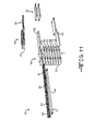
- FIGS. 11-30 are diagrammatic illustrations of another embodiment of an apparatus for compressing and packaging compressible batts, where the apparatus is shown in various positions, or stages, of a compressing/packaging cycle that the apparatus passes through while performing a method for compressing and packaging compressible batts.
- an apparatus and a method for compressing and packaging compressible batts are provided.
- the conveyor assembly includes a vertical stack of at least two conveyor systems. Adjacent pairs of conveyor systems within the conveyor assembly define a space between the pair of conveyor systems for receiving and conveying compressible batts.
- a pair of adjacent conveyor systems has: i) at least two upper belts in a coplanar relationship and positioned above and facing the space between the pair of conveyor systems, with one of the two upper belts positioned above the space mounted for traveling in an advancing direction relative to the conveyor assembly and the other of the two upper belts positioned above the space mounted for traveling in a returning direction; and, ii) and at least two lower belts in a coplanar relationship and positioned below and facing the space between the pair of conveyor systems, with one of the two lower belts positioned below the space mounted for traveling in the advancing direction relative to the conveyor assembly and the other of the two lower belts positioned below the space mounted for traveling in the returning direction.
- the assembly has shields associated with each of the belts traveling the returning direction.
- the shields are positioned to prevent contact between the belts and a compressible batt contained between the conveyor systems.
- the upper advancing belt and the lower returning belt are in a vertically aligned relationship, and the lower advancing belt and the upper returning belt are in a vertically aligned relationship.
- the present invention relates to a method for conveying compressible batts and for maintaining compression of multiple compressible batts by conveying multiple compressible batts using a conveyor assembly having a pair of adjacent conveyor systems.
- the method includes sequentially receiving individual batts in each space between the pair of conveyor systems; holding each individual batt in each space until a determined number of batts are held in the conveyor assembly; and, transferring the held batts as a stack of batts from the conveyor assembly.
- the present invention provides an apparatus and a method for compressing and packaging compressible batts.
- the apparatus maintains the batts, once at least partially compressed, substantially under compression without being allowed to expand during the stacking, compressing and packaging.
- the individual batts are kept separated while being compressed. This separation while the batts are being compressed makes it easier to maintain compression on each batt.
- the individual batts are gathered into stacks, and these stacks are kept separated while being further compressed. This separation while the stacks of batts are being further compressed also makes it easier to maintain compression on each batt.
- FIGS. 1-8 are schematic, side elevational, illustrations of one embodiment of an apparatus 10 for compressing and packaging compressible batts, such as batts of fiberglass materials.
- the batts once at least partially compressed, remain under compression substantially without being allowed to expand during the compressing and packaging.
- the apparatus 10 for compressing and packaging compressible batts can include a folding device (not shown) that generally folds the compressible batts.
- a folding device (not shown) that generally folds the compressible batts.
- the apparatus 10 generally includes a delivery assembly 12 for delivering a supply of successive compressible batts a 1 , a 2 , etc. to a stacking assembly 14 .
- the stacking assembly 14 sequentially compiles multiple compressible batts into a stack s 1 and simultaneously delivers the stack of compressible batts to a pre-compressing assembly 16 .
- the pre-compressing assembly 16 receives multiple stacks of compressible batts and “pre-compresses” the multiple stacks to a first stage of compression.
- the pre-compressing means 16 delivers the pre-compressed multiple stacks to a compressing assembly 18 .
- the compressing assembly 18 compresses the multiple, pre-compressed stacks into a batch b 1 and delivers the compressed batch b 1 to a packaging assembly 20 for packaging the compressed batches.
- the packaging assembly 20 for example, applies a suitable covering to the compressed batches.
- the delivery assembly 12 receives a plurality of compressible batts and delivers the compressible batts to a pivoting assembly 13 .
- the pivoting assembly 13 pivotably moves a continuous distributive conveyor 22 into a position adjacent individual stacking conveyors of the stacking assembly 14 , as described below.
- the stacking assembly 14 includes a set 30 of stacking conveyors.
- the set 30 of stacking conveyors includes eight stacking conveyors; it should be understood, however, that in certain embodiments, the stacking assembly 14 can contain fewer or more stacking conveyors.
- the stacking assembly 14 is incrementally movable with respect to the article delivery assembly 12 such that the stacking assembly 14 is adaptable for delivering multiple and separate compressible batts to individual conveyors of the pre-compressing assembly 16 .
- the pre-compressing assembly 16 includes a set 40 of pre-compressing conveyors. It is to be understood that in other embodiments, there can be a different number of pre-compressing conveyors, and that such embodiments are within the contemplated scope of the present invention.
- the pre-compressing assembly 16 is incrementally movable with respect to the stacking assembly 14 such that the pre-compressing assembly 16 is adaptable for delivering multiple and separate stacks of compressible batts to the compressing assembly 18 .
- the compressing assembly 18 includes a set 50 of compressing conveyors.
- the compressing assembly 18 includes a top compressing conveyor 51 and a bottom compressing conveyor 52 .
- the top compressing conveyor 51 and the bottom compressing conveyor 52 are positioned at an angle with respect to each other such that both the top compressing conveyor 51 and the bottom compressing conveyor 52 have leading edges 53 and 54 , respectively, that are adjacent the pre-compressing assembly 16 and, further, have trailing edges 55 and 56 , respectively, that are adjacent the packaging assembly 20 .
- the leading edges 53 and 54 are spaced a first distance d 1 from each other that is greater than a second distance d 2 between the trailing edges 55 and 56 .
- the numerals “ 5 ” and “ 6 ” generally depict the number of compressible batts present at the particular stage within pre-compressing assembly 16 as the compressible batts are being formed into stacks.
- the even smaller numerals “ 16 ” shown in FIGS. 4 and 8 depict the number of compressible batts at a stage in the process where the compressible batts are “compressed” into a batch.
- the numeral “ 4 ” generally depicts the number of compressible batts present at the particular stage within pre-compressing assembly 16 as the compressible batts are being formed into stacks.
- the larger numeral “ 4 ” shown in FIGS. 9A and 9B depicts such compressible batts at a stage in the process prior to being “pre-compressed”.
- the smaller numeral “ 4 ” shown in FIG. 9B depicts such compressible batts at a stage in the process where such compressible batts are “pre-compressed.
- the small numeral “ 8 ” shown in FIG. 10 depicts the number of compressible batts at a stage in the process where the compressible batts are “compressed” into a batch.
- FIGS. 11 through 30 depicted therein are diagrammatic illustrations of the multi-functional apparatus 10 for stacking, compressing and packaging compressible batts.
- the delivery assembly 12 includes the pivoting assembly 13 which delivers the compressible batts to the stacking assembly 14 where the stacking assembly 14 is stationery and does not move in a vertical direction.
- the delivery assembly 12 delivers compressible batts to the stacking assembly 14 which is capable of movement in a vertical direction.
- the compressing assembly 18 includes the set 50 of top compressing conveyor 51 and bottom compressing conveyor 52 that are positioned at an angle with respect to each other, while in FIGS. 11-30 , the set 50 of top and bottom compressing conveyors 51 and 52 , respectively, are in a parallel relationship.
- FIGS. 1-30 are within the contemplated scope of the present invention, and that the following description of compressible batts moving through the apparatus 10 is equally applicable to all embodiments described herein.
- the numerals, as used in the Figures, are kept the same for all embodiments.
- the delivery assembly 12 includes the continuous distributive conveyor 22 for delivering a plurality of compressible batts, numbered as a 1 , a 2 , a 3 , etc. herein, to the stacking assembly 14 .
- the stacking assembly 14 includes the set 30 multiple stacking conveyors. It is to be understood that in other embodiments, there can be a different number of stacking conveyors, and that such embodiments are within the contemplated scope of the present invention.
- the set 30 of conveyors includes a top engaging stacking conveyor 30 t , and a plurality of stacking conveyors, numbered herein as a first stacking conveyor 31 through a seventh stacking conveyor 37 .
- the first stacking conveyor 31 receives the first article a 1 from the distributive conveyor 22 , as shown in FIGS. 11-12 .
- the reciprocating stacking assembly 14 moves in an upward direction, as indicated by arrow A, such that the second stacking conveyor 32 is positioned adjacent the delivery conveyor 20 for receiving the second article a 2 .
- the reciprocating stacking assembly 14 moves in the upward direction such that the third stacking conveyor 33 is positioned adjacent the delivery conveyor 20 for receiving the third article a 3 , as shown in FIG. 13 .
- the reciprocating stacking assembly 14 continues to move in the upward direction until the sixth stacking conveyor 36 receives the sixth article a 6 , as shown in FIG. 14 .
- the first through sixth stacking conveyors 31 - 36 are operatively engaged, or activated, by the stacking assembly 14 such that the first through sixth compressible batts a 1 -a 6 are conveyed to the pre-compressing assembly 16 , as shown in FIG. 15 .
- the invention also contemplates that a bottom article, shown as seventh article a 7 , can be included in the stack s 1 so that the set 30 of stacking conveyors is operated most efficiently. Further, the adjacent article of a subsequent stack can be delivered to the bottom conveyor 36 as the article already on the conveyor is being conveyed to the pre-compressing assembly 16 .
- the pre-compressing assembly 16 includes a set 40 of pre-compressing conveyors. It is to be understood that in other embodiments, there can be a different number of pre-compressing conveyors, and that such embodiments are within the contemplated scope of the present invention.
- the set 40 of pre-compressing conveyors include a top engaging pre-compressing conveyor 40 t , and a plurality of stacking conveyors, numbered herein as a first pre-compressing conveyor 41 through a third pre-compressing conveyor 43 . It is to be understood that in other embodiments, there can be a different number of pre-compressing conveyors, and that such embodiments are within the contemplated scope of the present invention.
- the second pre-compressing conveyor 42 is in a planar relationship with the sixth stacking conveyor 36 and receives the compressible batts a 1 -a 6 , thereby forming a first stack s 1 .
- the delivery assembly 12 delivers a seventh article a 7 to the seventh stacking conveyor 37 , as shown in FIGS. 14 and 15 .
- the stacking assembly 14 is receiving additional compressible batts.
- the stacking assembly 14 begins to move in a downward direction, as indicated by arrow B, such that the delivery assembly 12 delivers an eighth article a 8 to the sixth stacking conveyor 36 , a ninth article a 9 to the fifth stacking conveyor 35 , a tenth article a 10 to the fourth stacking conveyor 34 , and an eleventh article a 11 to the third stacking conveyor 33 .
- the third stacking conveyor 33 through seventh stacking conveyor 37 are operatively engaged, or activated, by stacking assembly 14 such that the seventh through eleventh compressible batts a 7 -a 11 are conveyed to third pre-compressing conveyor 43 of the pre-compressing assembly 16 , as shown in FIG. 17 .
- the seventh through eleventh compressible batts a 7 -a 11 form a second stack s 2 .
- the continuous distributive conveyor 22 is delivering additional compressible batts to the stacking assembly 14 , as shown in FIG. 17 .
- the continuous distributive conveyor 22 delivers a twelfth article a 12 to the second stacking conveyor 32 , a thirteenth article a 13 to the third stacking conveyor 33 , a fourteenth article a 14 to the fourth stacking conveyor 34 , a fifteenth article a 15 to the fifth stacking conveyor 35 , and a sixteenth article a 16 to the sixth stacking conveyor 36 , as shown in FIG. 18 .
- the compressible batts a 12 through a 16 are being delivered to the stacking assembly 14 to form a third stack s 3 , as shown in FIG. 19 .
- the first pre-compressing conveyor 41 and the second pre-compressing conveyor 42 are operatively moved by the pre-compressing assembly 16 in a downward direction, as shown in FIGS. 18 and 19 by an arrow C.
- the first pre-compressing conveyor 41 and the second pre-compressing conveyor 42 are moved in a downward direction toward the third pre-compressing conveyor 43 such that the stacks s 1 and s 2 are compressed, as shown in FIG. 19 by the arrows D and E, respectively.
- the continuous distributive conveyor 22 While the stack s 3 is being conveyed to the first pre-compressing conveyor 41 , the continuous distributive conveyor 22 is delivering additional compressible batts to the stacking assembly 14 .
- the continuous distributive conveyor 22 delivers a seventeenth article a 17 to the seventh stacking conveyor 37 , an eighteenth article a 18 to the sixth stacking conveyor 36 , and so on as the stacking assembly 14 again moves in the downward direction.
- the pre-compressing assembly 16 reverses direction and moves in an upward direction, as indicated by arrow F, toward the first pre-compressing conveyor 41 , thereby compressing the third stack s 3 , as shown in FIG. 20 .
- the first pre-compressing conveyor 41 , the second pre-compressing conveyor 42 and the third pre-compressing conveyor 43 are operatively engaged, or activated by, the pre-compressing assembly 16 to convey the compressed stacks s 1 -s 3 to the compressing assembly 18 , as shown in FIGS. 20 and 21 .
- the compressing assembly 18 includes a top compressing conveyor 51 and a bottom compressing conveyor 52 .
- the top compressing conveyor 51 and the bottom compressing conveyor 52 are in an opposed and parallel relationship with respect to each other.
- the bottom compressing conveyor 52 is in a coplanar relationship with third pre-compressing conveyor 43 such that the stacks s 1 , s 2 and s 3 are delivered to the bottom compressing conveyor 52 .
- the top compressing conveyor 51 and the bottom compressing conveyor 52 are moved in a direction toward each other, as shown in FIG. 22 .
- the top compressing conveyor 51 and the bottom compressing conveyor 52 compress the stacks s 1 -s 3 to form a first batch b 1 .
- the top compressing conveyor 51 and bottom compressing conveyor 52 are operatively engaged, or activated by, the compressing assembly 18 to convey the batch b 1 to the packaging assembly 20 , as shown in FIG. 23 .
- the packaging assembly 20 includes a top packaging conveyor 61 and a bottom packaging conveyor 62 .
- the top packaging conveyor 61 and the bottom packaging conveyor 62 are in an opposed and parallel relationship.
- the continuous distributive conveyor 22 is delivering the compressible batts a 17 through a 22 to the stacking assembly 14 to form a fourth stack s 4 .
- the stacking assembly 14 is movable in a downward direction to receive the compressible batts a 17 -a 22 .
- the stack s 4 is delivered to the second pre-compressing conveyor 42 of the stacking assembly 14 .
- the continuous distributive conveyor 22 continues to deliver yet additional compressible batts, such as shown in FIG. 24 where an article a 23 is delivered to the first stacking conveyor 31 , and so on.
- FIG. 25 shows compressible batts a 23 through a 27 being conveyed to the first pre-compressing conveyor 41 of the stacking assembly 14 , thereby forming a fifth stack s 5 .
- the stacking assembly 14 continues to move in the upward direction while the sixth stacking conveyor 36 receives an article a 28 , as shown by arrow A in FIG. 25 .
- the stacking assembly 14 is engaged such that the stack s 5 is moved to first pre-compressing conveyor 41 , as shown in FIG. 26 .
- the stacking assembly 14 is moved in the downward direction, as shown by arrow B, and the stacking assembly 14 continues to receive compressible batts a 28 through a 32 , as shown in FIGS. 26 and 27 .
- the second stacking conveyor 32 through the sixth stacking conveyor 36 are operatively engaged by the stacking assembly 14 are moved by stacking assembly 14 to the pre-compressing assembly pre-compressing assembly 16 to form a sixth stack s 6 .
- the first pre-compressing conveyor 41 and the second pre-compressing conveyor 42 are moved in the upward direction toward the top engaging pre-compressing conveyor 40 t while the pre-compressing assembly 16 is delivering the sixth stack s 6 to the third pre-compressing conveyor third pre-compressing conveyor 43 , and the first pre-compressing conveyor 41 and second pre-compressing conveyor 42 are moved in a vertical direction toward the third pre-compressing conveyor 43 .
- the pre-compressing assembly 16 activates the top pre-compressing conveyor 40 t , the first pre-compressing conveyor 41 , the second pre-compressing conveyor 42 , and the third pre-compressing conveyor 43 to convey the stacks s 4 -s 6 to the compressing assembly 18 , as shown in FIGS. 28 and 29 .
- the top compressing conveyor 51 and the bottom compressing conveyor 52 are moved in a direction toward each other such that a second batch b 2 is formed.
- the batch b 2 contains the compressed stacks s 4 -s 6 , as shown in FIGS. 29 and 30 .
- the top compressing conveyor 51 and the bottom compressing conveyor 52 of the compressing assembly 18 are moved in a direction toward each other and compress the multiple, pre-compressed stacks s 4 , s 5 and s 6 into a batch b 2 .
- the compressing assembly 18 delivers the compressed batch b 2 to the packaging assembly 20 for packaging and/or covering the compressed batches b 2 .
Abstract
Description
Claims (27)
Priority Applications (1)
| Application Number | Priority Date | Filing Date | Title |
|---|---|---|---|
| US11/364,221 US7281622B2 (en) | 2006-02-28 | 2006-02-28 | Conveyor system for high speed, high performance bagger |
Applications Claiming Priority (1)
| Application Number | Priority Date | Filing Date | Title |
|---|---|---|---|
| US11/364,221 US7281622B2 (en) | 2006-02-28 | 2006-02-28 | Conveyor system for high speed, high performance bagger |
Publications (2)
| Publication Number | Publication Date |
|---|---|
| US20070199800A1 US20070199800A1 (en) | 2007-08-30 |
| US7281622B2 true US7281622B2 (en) | 2007-10-16 |
Family
ID=38442951
Family Applications (1)
| Application Number | Title | Priority Date | Filing Date |
|---|---|---|---|
| US11/364,221 Expired - Fee Related US7281622B2 (en) | 2006-02-28 | 2006-02-28 | Conveyor system for high speed, high performance bagger |
Country Status (1)
| Country | Link |
|---|---|
| US (1) | US7281622B2 (en) |
Cited By (6)
| Publication number | Priority date | Publication date | Assignee | Title |
|---|---|---|---|---|
| US20100040442A1 (en) * | 2008-08-14 | 2010-02-18 | Arne Roy Jorgensen | High speed roofing shingle making machine including cutter, catcher and stacker |
| US20140245797A1 (en) * | 2011-09-30 | 2014-09-04 | Owens Corning Intellectual Capital, Llc | Method of forming a web from fibrous material |
| US20170200248A1 (en) * | 2016-01-13 | 2017-07-13 | Christopher J. Murphy | System And Method For Storing And Sequencing Luggage Items |
| CN111498464A (en) * | 2020-04-10 | 2020-08-07 | 陈善兰 | Disc part distribution machine |
| US10787303B2 (en) | 2016-05-29 | 2020-09-29 | Cellulose Material Solutions, LLC | Packaging insulation products and methods of making and using same |
| US11078007B2 (en) | 2016-06-27 | 2021-08-03 | Cellulose Material Solutions, LLC | Thermoplastic packaging insulation products and methods of making and using same |
Families Citing this family (3)
| Publication number | Priority date | Publication date | Assignee | Title |
|---|---|---|---|---|
| US10093442B1 (en) * | 2014-10-10 | 2018-10-09 | Valley Tissue Packaging, Inc. | Infeed system and method for product packaging machine |
| CN109834056B (en) * | 2019-03-22 | 2020-10-23 | 平度市林焱精密机械厂 | Full-automatic fruit sorting method |
| CN115367199B (en) * | 2022-10-24 | 2023-01-10 | 徐州博导信息科技有限公司 | Manufacturing and packaging equipment based on intelligent vehicle-mounted equipment |
Citations (21)
| Publication number | Priority date | Publication date | Assignee | Title |
|---|---|---|---|---|
| US2467291A (en) | 1944-10-09 | 1949-04-12 | Gustin Bacon Mfg Co | Process for forming felted fibrous insulating material |
| US3660964A (en) | 1969-07-24 | 1972-05-09 | Msl Ind Inc | Material guide members for a compressing and conveying apparatus |
| US3805489A (en) * | 1972-04-17 | 1974-04-23 | Bemis Co Inc | Automatic bag shaping and bag top forming apparatus |
| US3837138A (en) | 1973-02-23 | 1974-09-24 | Johns Manville | Method and apparatus for compressing material and enclosing the same in a plastic film |
| US3991538A (en) | 1975-01-27 | 1976-11-16 | Owens-Corning Fiberglas Corporation | Packaging apparatus for compressible strips |
| JPS54118086A (en) | 1978-03-03 | 1979-09-13 | Hitachi Ltd | Compound conveyor |
| US4287983A (en) | 1978-06-21 | 1981-09-08 | Hoogovens Ijmuiden, B.V. | Conveyors having a plurality of driven endless chains |
| US4591043A (en) | 1983-04-22 | 1986-05-27 | The Mead Corporation | Mechanism for spacing and conveying articles in a packaging machine |
| US4676361A (en) | 1985-09-03 | 1987-06-30 | Heisler Raymond A | Troughing conveyors for carton or bag orienting and conveying |
| US4750728A (en) * | 1984-11-26 | 1988-06-14 | Ferag Ag | Apparatus for loading a processing means for processing flexible flat products, especially printed products |
| US4902184A (en) * | 1987-07-01 | 1990-02-20 | Fritz Guenther | Apparatus for grouping of packages |
| US5341915A (en) | 1992-11-06 | 1994-08-30 | Kliklok Corporation | Article phasing, transfer and squaring system for packaging line |
| US5511651A (en) | 1993-11-05 | 1996-04-30 | U.S. Philips Corporation | Arrangement for the transport of printed circuit boards |
| US5635235A (en) * | 1994-02-07 | 1997-06-03 | Machine Masters, Inc. | Methods for handling masa |
| US5660262A (en) | 1995-01-13 | 1997-08-26 | Kliklok Corporation | High speed carton feeding/turning system |
| US5755851A (en) | 1994-05-10 | 1998-05-26 | Owens Corning Fiberglas Technology Inc. | Direct forming method of collecting long wool fibers |
| US5875697A (en) * | 1996-08-01 | 1999-03-02 | Urschel Laboratories Inc. | Apparatus for conveying food products of varying sizes |
| US5975282A (en) | 1996-01-16 | 1999-11-02 | Jervis B. Webb Company | Method and apparatus for storing and dispensing thin flexible objects |
| US6298529B1 (en) * | 2000-05-17 | 2001-10-09 | Saint-Gobain Isover | Method for the formation and conditioning of insulating felts and a device to implement the formation and conditioning |
| US6390766B1 (en) | 1999-11-30 | 2002-05-21 | Owens Corning Fiberglas Technology, Inc. | Shingle bundle palletizer with improved metering conveyor, pattern conveyor and shuttle conveyor |
| US7156222B2 (en) * | 2004-10-15 | 2007-01-02 | Campbell Wrapper Corporation | Magazine apparatus for retaining flexible bags |
-
2006
- 2006-02-28 US US11/364,221 patent/US7281622B2/en not_active Expired - Fee Related
Patent Citations (21)
| Publication number | Priority date | Publication date | Assignee | Title |
|---|---|---|---|---|
| US2467291A (en) | 1944-10-09 | 1949-04-12 | Gustin Bacon Mfg Co | Process for forming felted fibrous insulating material |
| US3660964A (en) | 1969-07-24 | 1972-05-09 | Msl Ind Inc | Material guide members for a compressing and conveying apparatus |
| US3805489A (en) * | 1972-04-17 | 1974-04-23 | Bemis Co Inc | Automatic bag shaping and bag top forming apparatus |
| US3837138A (en) | 1973-02-23 | 1974-09-24 | Johns Manville | Method and apparatus for compressing material and enclosing the same in a plastic film |
| US3991538A (en) | 1975-01-27 | 1976-11-16 | Owens-Corning Fiberglas Corporation | Packaging apparatus for compressible strips |
| JPS54118086A (en) | 1978-03-03 | 1979-09-13 | Hitachi Ltd | Compound conveyor |
| US4287983A (en) | 1978-06-21 | 1981-09-08 | Hoogovens Ijmuiden, B.V. | Conveyors having a plurality of driven endless chains |
| US4591043A (en) | 1983-04-22 | 1986-05-27 | The Mead Corporation | Mechanism for spacing and conveying articles in a packaging machine |
| US4750728A (en) * | 1984-11-26 | 1988-06-14 | Ferag Ag | Apparatus for loading a processing means for processing flexible flat products, especially printed products |
| US4676361A (en) | 1985-09-03 | 1987-06-30 | Heisler Raymond A | Troughing conveyors for carton or bag orienting and conveying |
| US4902184A (en) * | 1987-07-01 | 1990-02-20 | Fritz Guenther | Apparatus for grouping of packages |
| US5341915A (en) | 1992-11-06 | 1994-08-30 | Kliklok Corporation | Article phasing, transfer and squaring system for packaging line |
| US5511651A (en) | 1993-11-05 | 1996-04-30 | U.S. Philips Corporation | Arrangement for the transport of printed circuit boards |
| US5635235A (en) * | 1994-02-07 | 1997-06-03 | Machine Masters, Inc. | Methods for handling masa |
| US5755851A (en) | 1994-05-10 | 1998-05-26 | Owens Corning Fiberglas Technology Inc. | Direct forming method of collecting long wool fibers |
| US5660262A (en) | 1995-01-13 | 1997-08-26 | Kliklok Corporation | High speed carton feeding/turning system |
| US5975282A (en) | 1996-01-16 | 1999-11-02 | Jervis B. Webb Company | Method and apparatus for storing and dispensing thin flexible objects |
| US5875697A (en) * | 1996-08-01 | 1999-03-02 | Urschel Laboratories Inc. | Apparatus for conveying food products of varying sizes |
| US6390766B1 (en) | 1999-11-30 | 2002-05-21 | Owens Corning Fiberglas Technology, Inc. | Shingle bundle palletizer with improved metering conveyor, pattern conveyor and shuttle conveyor |
| US6298529B1 (en) * | 2000-05-17 | 2001-10-09 | Saint-Gobain Isover | Method for the formation and conditioning of insulating felts and a device to implement the formation and conditioning |
| US7156222B2 (en) * | 2004-10-15 | 2007-01-02 | Campbell Wrapper Corporation | Magazine apparatus for retaining flexible bags |
Cited By (9)
| Publication number | Priority date | Publication date | Assignee | Title |
|---|---|---|---|---|
| US20100040442A1 (en) * | 2008-08-14 | 2010-02-18 | Arne Roy Jorgensen | High speed roofing shingle making machine including cutter, catcher and stacker |
| US8439184B2 (en) * | 2008-08-14 | 2013-05-14 | Arne Roy Jorgensen | High speed roofing shingle making machine including cutter, catcher and stacker |
| US20140245797A1 (en) * | 2011-09-30 | 2014-09-04 | Owens Corning Intellectual Capital, Llc | Method of forming a web from fibrous material |
| US11939255B2 (en) * | 2011-09-30 | 2024-03-26 | Owens Corning Intellectual Capital, Llc | Method of forming a web from fibrous material |
| US20170200248A1 (en) * | 2016-01-13 | 2017-07-13 | Christopher J. Murphy | System And Method For Storing And Sequencing Luggage Items |
| US10643294B2 (en) * | 2016-01-13 | 2020-05-05 | Jervis B. Webb Company | System and method for storing and sequencing luggage items |
| US10787303B2 (en) | 2016-05-29 | 2020-09-29 | Cellulose Material Solutions, LLC | Packaging insulation products and methods of making and using same |
| US11078007B2 (en) | 2016-06-27 | 2021-08-03 | Cellulose Material Solutions, LLC | Thermoplastic packaging insulation products and methods of making and using same |
| CN111498464A (en) * | 2020-04-10 | 2020-08-07 | 陈善兰 | Disc part distribution machine |
Also Published As
| Publication number | Publication date |
|---|---|
| US20070199800A1 (en) | 2007-08-30 |
Similar Documents
| Publication | Publication Date | Title |
|---|---|---|
| US7281622B2 (en) | Conveyor system for high speed, high performance bagger | |
| US6145281A (en) | Method and apparatus for packaging a series of articles in different formations | |
| CN210527036U (en) | Discharging device of boxing machine | |
| US7409813B2 (en) | High speed, high performance bagging assembly | |
| EP1417127B1 (en) | Conveyor assembly for packagings, and method for delivery of a pack | |
| US7452178B2 (en) | Unit and method for forming packs of products for a packaging machine | |
| US5970834A (en) | Depalletizer and hopper feeder | |
| CN205525197U (en) | Novel stromatolite packagine machine | |
| CN102963556A (en) | Tray-free packing method and tray-free packing device of brick stack | |
| US7243484B2 (en) | Apparatus and method for loading a packaging station of an insulation batt packager | |
| CN110758823A (en) | Automatic arrangement packing apparatus of cardboard | |
| CN203946298U (en) | A kind of paper angle protector material strip is tied up bunching device | |
| US5882175A (en) | Stacker for flexible sheets | |
| JP2012066851A (en) | Method and device for binding and stacking paper tubes | |
| US6695570B2 (en) | Automatic carton loader | |
| KR200473115Y1 (en) | A Array Unit of Cosmetic Box | |
| CN213323935U (en) | Aligning device of automatic carton packaging machine | |
| US20080263997A1 (en) | Folding blade for insulation bagger | |
| CN109178509A (en) | Full-automation vanning stacking production line | |
| CN202213228U (en) | Inner film bag distribution mechanism for packaging bag processing machine | |
| CN117302644A (en) | Automatic boxing line for jelly strips | |
| JPH08175662A (en) | Device for carrying,sorting and storage | |
| EP0133945A1 (en) | Signature handling apparatus | |
| CN116252994A (en) | Flexible packaging production line for electronic cigarettes | |
| CN213323897U (en) | Automatic packing plant of carton |
Legal Events
| Date | Code | Title | Description |
|---|---|---|---|
| AS | Assignment |
Owner name: OWENS-CORNING FIBERGLAS TECHNOLOGY, INC., ILLINOIS Free format text: ASSIGNMENT OF ASSIGNORS INTEREST;ASSIGNOR:QI, WEIGANG;REEL/FRAME:017836/0180 Effective date: 20060407 |
|
| AS | Assignment |
Owner name: OWENS CORNING INTELLECTUAL CAPITAL, LLC, OHIO Free format text: ASSIGNMENT OF ASSIGNORS INTEREST;ASSIGNOR:OWENS-CORNING FIBERGLASS TECHNOLOGY, INC.;REEL/FRAME:019795/0433 Effective date: 20070803 Owner name: OWENS CORNING INTELLECTUAL CAPITAL, LLC,OHIO Free format text: ASSIGNMENT OF ASSIGNORS INTEREST;ASSIGNOR:OWENS-CORNING FIBERGLASS TECHNOLOGY, INC.;REEL/FRAME:019795/0433 Effective date: 20070803 Owner name: OWENS CORNING INTELLECTUAL CAPITAL, LLC, OHIO Free format text: ASSIGNMENT OF ASSIGNORS INTEREST;ASSIGNOR:OWENS-CORNING FIBERGLAS TECHNOLOGY, INC.;REEL/FRAME:019795/0433 Effective date: 20070803 |
|
| REMI | Maintenance fee reminder mailed | ||
| LAPS | Lapse for failure to pay maintenance fees | ||
| STCH | Information on status: patent discontinuation |
Free format text: PATENT EXPIRED DUE TO NONPAYMENT OF MAINTENANCE FEES UNDER 37 CFR 1.362 |
|
| FP | Lapsed due to failure to pay maintenance fee |
Effective date: 20111016 |