US7280148B2 - Optical control system - Google Patents
Optical control system Download PDFInfo
- Publication number
- US7280148B2 US7280148B2 US10/827,849 US82784904A US7280148B2 US 7280148 B2 US7280148 B2 US 7280148B2 US 82784904 A US82784904 A US 82784904A US 7280148 B2 US7280148 B2 US 7280148B2
- Authority
- US
- United States
- Prior art keywords
- control
- switching
- section
- command signal
- optical
- Prior art date
- Legal status (The legal status is an assumption and is not a legal conclusion. Google has not performed a legal analysis and makes no representation as to the accuracy of the status listed.)
- Expired - Fee Related, expires
Links
Images


Classifications
-
- G—PHYSICS
- G02—OPTICS
- G02B—OPTICAL ELEMENTS, SYSTEMS OR APPARATUS
- G02B27/00—Optical systems or apparatus not provided for by any of the groups G02B1/00 - G02B26/00, G02B30/00
- G02B27/28—Optical systems or apparatus not provided for by any of the groups G02B1/00 - G02B26/00, G02B30/00 for polarising
- G02B27/281—Optical systems or apparatus not provided for by any of the groups G02B1/00 - G02B26/00, G02B30/00 for polarising used for attenuating light intensity, e.g. comprising rotatable polarising elements
-
- H—ELECTRICITY
- H04—ELECTRIC COMMUNICATION TECHNIQUE
- H04N—PICTORIAL COMMUNICATION, e.g. TELEVISION
- H04N23/00—Cameras or camera modules comprising electronic image sensors; Control thereof
- H04N23/60—Control of cameras or camera modules
- H04N23/67—Focus control based on electronic image sensor signals
- H04N23/673—Focus control based on electronic image sensor signals based on contrast or high frequency components of image signals, e.g. hill climbing method
-
- H—ELECTRICITY
- H04—ELECTRIC COMMUNICATION TECHNIQUE
- H04N—PICTORIAL COMMUNICATION, e.g. TELEVISION
- H04N23/00—Cameras or camera modules comprising electronic image sensors; Control thereof
- H04N23/60—Control of cameras or camera modules
- H04N23/665—Control of cameras or camera modules involving internal camera communication with the image sensor, e.g. synchronising or multiplexing SSIS control signals
Definitions
- the present invention relates to optical control systems used in optical apparatuses, such as television cameras, video cameras, television lenses, video lenses or the like, that can perform automatic focus control (referred to as “AF control” in the following) as well as manual focus control (referred to as “MF control” in the following).
- AF control automatic focus control
- MF control manual focus control
- Optical apparatuses which have an AF control function, such as the optical apparatus disclosed in FIG. 1 of Japanese Patent Application Laid Open No. H9 (1997)-65184, for example.
- optical apparatuses which perform focus control of an image-taking optical system by extracting, from the taken video signals, a signal (high-frequency components) related to the sharpness of the object, which corresponds to the focusing state of the image-taking optical system, and evaluating that signal, in order to perform AF control.
- reference numeral 1600 denotes a video camera with integrated image-taking lens.
- Reference numeral 1102 denotes an evaluation value generation circuit, which generates a sharpness evaluation signal from a video signal output by a later-described process circuit 1202
- reference numeral 1103 denotes an AF driving control circuit, which generates such a motor control signal that the sharpness evaluation value generated by the evaluation value generation circuit 1102 becomes maximal.
- Reference numeral 1105 denotes a motor, whose rotation speed is controlled by the AF driving control circuit 1103
- reference numeral 1106 denotes a focus lens, which receives the driving force of the motor 1105 and is moved in the direction of the optical axis.
- Reference numeral 1201 denotes a CCD, which photoelectrically converts object images formed by the image-taking optical system (not shown in its entirety in FIG. 8 ) including the focus lens 1106 .
- the process circuit 1202 processes the output signal from the CCD 1201 and turns it into a video signal in accordance with a predetermined format, such as NTSC or PAL format.
- Reference numeral 1203 denotes a recording/reproducing circuit, which records the video signal output from the process circuit 1202 onto a recording medium, such as a tape, a semiconductor memory or the like.
- light flux which has passed through the image-taking optical system forms an image on an image-pickup surface of the CCD 1201 , and after being photoelectrically converted by the CCD 1201 , the signal output from the CCD 1201 is sampled and held and input into the process circuit 1202 .
- the process circuit 1202 processes the input signal into a video signal of the predetermined format, and outputs the video signal to the evaluation value generation circuit 1102 and the recording/reproducing circuit 1203 .
- the evaluation value generation circuit 1102 By filtering the input video signal, the evaluation value generation circuit 1102 generates, at vertical synchronization units of the video signal, sharpness evaluation value signals related to the high-frequency components of the video signal, and outputs the sharpness evaluation value signals to the AF driving control circuit 1103 . While driving the motor 1105 to move the focus lens 1106 by incremental steps, the AF driving control circuit 1103 compares, at vertical synchronization units, the sharpness evaluation value signals, which are successively input from the evaluation value generation circuit 1102 , and moves the focus lens 1106 to a position where the sharpness evaluation value becomes maximal. Thus, the focus lens 1106 attains an in-focus position.
- the recording/reproducing circuit 1203 records the video signal output from the process circuit 1202 to a recording medium. It should be noted that the recording/reproducing circuit 1203 also performs the reproducing of video recorded on the recording medium.
- Patent Document 1 A camera system performing such AF control is disclosed in Patent Document 1, for example.
- optical apparatuses for special applications such as surveillance, which can be operated remotely.
- Many of such optical apparatuses are not equipped with an AF control function, and in this case, they are configured for remote control of the focus, with the user operating a switch or knob or the like provided on a remote control unit.
- FIG. 9 A system adapted for such remote focus operation is explained with reference to FIG. 9 .
- structural elements that are the same as in FIG. 8 are given the same reference numerals as in FIG. 8 and are not further explained.
- Reference numeral 1400 denotes a remote control unit, which supplies command signals for driving a zoom lens, an iris (not shown in the drawings) and the focus lens 1106 of the image-taking optical system to a camera 1600 , from a location that is at a certain distance to the camera 1600 .
- reference numeral 1401 denotes an MF command signal generation circuit, which generates an MF command signal in accordance with the operation of a switch or a knob (not shown in the drawings), and reference numeral 1404 denotes a remote control-side connector, which is connected to a remote control cable 1500 , and through which the MF command signal is output to the camera 1600 .
- reference numeral 1107 denotes a camera-side connector to which the remote cable 1500 is connected
- reference numeral 1109 denotes an MF driving control circuit, which generates a motor control signal for driving the motor 1105 , based on the manual focus (MF) command signal from the remote control unit 1400 .
- the focus lens is moved in the optical axis direction by driving the motor 1105 with the motor control signal from the MF driving control circuit 1109 .
- MF manual focus
- an electrical interface is established between the remote control unit and the camera, and the number of connecter pins (terminals) is set to twelve. And in their current form, the command signals for zoom, iris and focus, as well as the various control mode signals (for switching high-speed control and position control, for example), power and ground are assigned to these twelve pins, and there are no free pins left.
- an optical control system comprises a control unit and an optical apparatus.
- the control unit comprises a command signal generation section, which generates a command signal in response to operation of an operating member, and a first connector, which is connected to a communication cable and outputs the command signal from a first terminal thereof via the communication cable.
- the optical apparatus comprises an optical adjusting member, which is movable to perform an optical action, an actuator driving the optical adjusting member, a second connector which is connected to the communication cable, a first control section, which controls the actuator based on the command signal input via a second terminal of the second connector from the control unit, a second control section, which controls the actuator based on predetermined information, and a control switching section, which selects, from the first and the second control sections, the control section controlling the driving of the actuator.
- the control unit comprises an output switching section, which is switchable between a first state, in which the command signal from the command signal generation section is output via the first terminal of the first connector, and a second state, in which a switching signal for selecting the second control section, the voltage level of the switching signal being different from that of the command signal, is output from the first terminal.
- the control switching section of the optical apparatus selects the first control section in response to input of the command signal, and selects the second control section in response to the switching signal input, which is input from the same terminal of the second connector as the command signal.
- an optical control system comprises a control unit and an optical apparatus.
- the control unit comprises a command signal generation section, which generates a command signal in response to operation of an operating member, and a first connector, which is connected to a communication cable and outputs the command signal from a first terminal thereof via the communication cable.
- the optical apparatus comprises an optical adjusting member, which is movable to perform an optical action, an actuator driving the optical adjusting member, a second connector which is connected to the communication cable, a first control section, which controls the actuator based on the command signal input via a second terminal of the second connector from the control unit, a second control section, which controls the actuator based on predetermined information, and a control switching section, which selects, from the first and the second control sections, the control section controlling the driving of the actuator.
- the control unit comprises an output switching section, which is switchable from a first state, in which the command signal from the command signal generation section is output via the first terminal of the first connector, to a second state, in which a switching signal for selecting one of the first control section and the second control section, is output from the first terminal, the output switching section being restored to the first state from the second state when the switching operation is released.
- the control switching section of the optical apparatus selects the first control section and the second control section in alternation in response to input of the switching signal from the second terminal of the second connector, and the first control section is selected when the command signal is input while the second control section is selected.
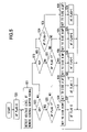
- FIG. 1 shows the structure of an optical control system according to Embodiment 1 of the present invention.
- FIG. 2 is a flowchart showing the operation of the optical control system according to Embodiment 1.
- FIG. 3 shows the structure of an optical control system according to Embodiment 2 of the present invention.
- FIG. 4 shows the structure of an optical control system according to Embodiment 3 of the present invention.
- FIG. 5 is a flowchart showing the operation of the optical control system according to Embodiment 3.
- FIG. 6 is a timing chart showing a specific example of the operation of the optical control system of Embodiment 3.
- FIG. 7 shows the structure of an optical control system according to Embodiment 4 of the present invention.
- FIG. 8 shows the structure of a conventional optical apparatus.
- FIG. 9 shows the structure of a conventional optical control system.
- FIG. 1 shows the structure of an optical control system according to Embodiment 1 of the present invention.
- reference numeral 600 denotes a video camera incorporating an image-taking optical system 110
- reference numeral 400 denotes a remote control unit.
- the remote control unit 400 outputs command signals for driving a zoom lens, an iris (not shown in the drawings) and a focus lens 106 in the image-taking optical system 110 to the camera 600 , from a location that is at a certain distance to the camera 600 .
- Reference numeral 500 denotes a remote control cable connecting the camera 600 and the remote control unit 400 .
- reference numeral 401 denotes an MF command signal generation circuit, which generates an MF command signal for MF control of the focus lens 106 .
- the MF command signal generation circuit 401 generates an MF command signal, which causes the focus lens 106 to move in a direction corresponding to the direction in which a potentiometer-type switch (dial-type or seesaw-type) 401 a is operated, in proportion to the operated amount.
- Reference numeral 402 denotes an AF/MF switching signal input circuit, which outputs an AF switching signal for selecting AF control of the focus lens 106 .
- Reference numeral 403 denotes a command/switching signal circuit.
- This command/switching signal circuit 403 selectively outputs the MF command signal from the MF command signal generation circuit 401 or the AF switching signal from the AF/MF switching signal input circuit 402 to the same predetermined pin 404 a , which is one of the twelve terminals (pins) of the remote control-side connector (first connector) 404 .
- the command/switching signal circuit 403 is configured to have a switching contact piece 403 a , which is connected to the pin 404 a and is switchable between a state of contacting an MF contact connected to the MF command signal generation circuit 401 (MF position: referred to as “first state” in the claims) and a state of contacting an AF contact connected to the AF/MF switching signal input circuit 402 (AF position: referred to as “second state” in the claims).
- MF position referred to as “first state” in the claims
- AF position referred to as “second state” in the claims.
- the AF/MF switching signal input circuit 402 and the command/switching signal circuit 403 constitute what is referred to in the claims as an “output switching section.”
- reference numeral 102 denotes an evaluation value generation circuit (focus information generation section), which generates a sharpness evaluation value signal from the video signal output from a process circuit 202 (explained later), and reference numeral 103 denotes an AF driving control circuit, which generates such a motor control signal that the sharpness evaluation value generated by the evaluation value generation circuit 102 becomes maximal.
- Reference numeral 104 denotes an AF/MF switching circuit, which is controlled by a later-described AF/MF switching judgment circuit 108 , and which is switched depending on whether the focus lens 106 is driven by a control signal from the AF driving control circuit (first control section) 103 or whether it is driven by a control signal from a later-described MF driving control circuit (second control section) 109 .
- the AF/MF switching judgment circuit 108 and the AF/MF switching circuit 104 constitute what is referred to in the claims as a “control switching section.”
- Reference numeral 105 denotes a motor, which is operated by the control signals input from the AF driving control circuit 103 and the MF driving control circuit 109 via the AF/MF switching circuit 104 .
- Reference numeral 107 denotes a camera-side connector (second connector), to which the remote control cable 500 is connected.
- the AF/MF switching judgment circuit 108 is connected to a pin 107 a in the camera-side connector 107 , this pin 107 a being an input terminal for the MF command signal sent from the remote control unit 400 to the MF driving control circuit 109 . Therefore, the MF command signal and the AF switching signal from the AF/MF switching signal input circuit 402 are input into the AF/MF switching judgment circuit 108 .
- the AF/MF switching judgment circuit 108 judges whether the input signal is an MF command signal or an AF switching signal and, depending on the result of this judgment, switches the AF/MF switching circuit 104 to the MF driving control circuit 109 or the AF driving control circuit 103 .
- the AF/MF switching circuit 104 includes a movable contact piece 104 a , which is switchable between a state in which it contacts a contact B connected to the MF driving control circuit 109 and a state in which it contacts a contact A connected to the AF driving control circuit 103 , as well as an electromagnet (not shown in the drawings), which drives the movable contact piece 104 a .
- the AF/MF switching judgment circuit 108 sends a current through the electromagnet of the AF/MF switching circuit 104 , generating a force pulling the movable contact piece 104 a to the contact A, and setting the movable contact piece 104 a to the contact A.
- the AF/MF switching judgment circuit 108 does not send a current through the electromagnet of the AF/MF switching circuit 104 (or stops the current if a current has been sent up to that time), setting the movable contact piece 104 a by spring force to the contact B.
- the MF driving control circuit 109 generates a control signal, which drives the motor 105 , based on the MF command signal from the remote control unit 400 .
- Reference numeral 201 denotes an image-pickup device made of a CCD or CMOS sensor or the like.
- the process circuit 202 processes the signals output from the image-pickup device 201 to generate a video signal of a predetermined format, such as NTSC or PAL format.
- Reference numeral 203 denotes a recording/reproducing circuit, which records the video signal output from the process circuit 202 onto a recording medium, such as a tape, a semiconductor memory, an optical disk or the like, or reproduces the recorded video.
- a recording medium such as a tape, a semiconductor memory, an optical disk or the like
- light flux which has passed through the image-taking optical system 110 forms an image on an image-pickup surface of the image-pickup device 201 , and after being photoelectrically converted by the image-pickup device 201 , the electrical signal output from the image-pickup device 201 is sampled and held and input into the process circuit 202 .
- the process circuit 202 processes the input signal into a video signal of the predetermined format, and outputs the video signal to the evaluation value generation circuit 102 and the recording/reproducing circuit 203 .
- the evaluation value generation circuit 102 In AF control, by filtering the input video signal, the evaluation value generation circuit 102 generates, at vertical synchronization units of the video signal, a sharpness evaluation value signal related to the high-frequency components of the video signal, and outputs the sharpness evaluation value signal to the AF driving control circuit 103 . While driving the motor 105 to move the focus lens 106 by incremental steps, the AF driving control circuit 103 compares, at vertical synchronization units, the sharpness evaluation value signals, which are successively input from the evaluation value generation circuit 102 , and moves the focus lens 106 to a position where the sharpness evaluation value becomes maximal, that is, to the in-focus position. Thus, AF control of the focus lens 106 is performed.
- the AF driving control circuit 103 moves the focus lens 106 in incremental steps, and depending on the change of the sharpness evaluation value in that situation, it is judged whether the in-focus position is further to the tele-angle side or further to the wide-angle side with respect to the current position of the focus lens 106 , that is, a driving direction judgment is performed. After that, in accordance with the result of the driving direction judgment, the focus lens 106 is moved at a certain speed in order to detect the peak value of the sharpness evaluation value. This is also referred to as “hill-climbing.” After the peak value has been exceeded, the movement direction of the focus lens 106 is reversed, and the focus lens 106 is moved in incremental steps such that it is guided to the position where the sharpness evaluation value becomes maximal. This is referred to as “peak-finding.” Thus, the AF control of the focus lens 106 is finished.
- the sharpness evaluation value is compared with the value found as the peak, while reading the sharpness evaluation value, and if the sharpness evaluation value has changed, then the AF control is started again.
- the MF command signal from the MF command signal generation circuit 401 is a signal in the voltage range of +2.5 V (Volt) to +7.5 V. That is to say, if the focus lens 106 is speed-controlled, +5.0 V is taken as a stop command signal, in case of +5.0 V to +7.5 V, the focus lens 106 is driven towards infinity and in case of +5.0 V to +2.5 V, the focus lens 106 is driven towards close-range. Moreover, the driving speed of the focus lens 106 (the motor 105 ) at this time is faster the further the voltage of the MF command signal is removed from +5.0 V, and is the maximal possible driving speed at +7.5 V and +2.5 V, respectively.
- the AF switching signal from the AF/MF switching signal input circuit 402 is set to 0V, which is outside the voltage range of the MF command signal.
- the AF/MF switching judgment circuit 108 operates in accordance with the flowchart shown in FIG. 2 .
- Step 10 the voltage level of the output signal input from the remote control unit 400 is detected.
- Step 11 it is judged whether the detected voltage level is within the voltage range of the MF command signal (+2.5 V to +7.5 V). If it is within the voltage range of the MF command signal, the procedure advances to Step 12 , and no current is sent through the electromagnet, so that the AF/MF switching circuit 104 is set to the side of the contact B (MF control).
- MF control directional and speed control
- Step 11 if at Step 11 the detected voltage level is outside the voltage range of the MF command signal (that is, if the detected voltage level is 0V and thus an AF switching signal), then the procedure advances to Step 13 , and a current is sent through the electromagnet, so that the AF/MF switching circuit 104 is set to the side of the contact A (AF control).
- the control signal from the AF driving control circuit 103 is input into the motor 105 , and the above-mentioned AF control is performed.
- the program shown in the flowchart is executed repeatedly while the system is in operation, and by switching the command/switching signal circuit 403 to the MF position while in the AF control state, the camera 600 switches immediately to the MF control state, and by switching the command/switching signal circuit 403 to the AF position while in the MF control state, the camera 600 switches immediately to the AF control state.
- the present embodiment uses the pins 404 a and 107 a of the connectors 404 and 107 , which are assigned for sending MF command signals from the remote control unit 400 to the camera 600 , so that it is possible to switch the camera 600 between MF control and AF control from the remote control unit 400 .
- MF control and AF control can be switched from the remote control unit even if the electrical interface (connector) has no free terminals (pins), that is, no terminals that are not assigned otherwise, and it is possible to make the operation of the optical control system more convenient.
- Embodiment 1 a camera with integrated lens was explained, in which the camera 600 incorporates the image-taking optical system 110 , but the present invention can also be applied to optical control systems having an exchangeable lens unit (optical apparatus) that is freely attachable/detachable with respect to the camera.
- an exchangeable lens unit optical apparatus
- FIG. 3 shows the structure of an optical control system according to Embodiment 2 of the present invention.
- reference numeral 100 denotes an exchangeable lens unit
- reference numeral 200 denotes a video camera
- Reference numeral 300 denotes a coaxial video cable connected to the exchangeable lens unit 100 and the camera 200 .
- Embodiment 1 structural elements that are the same as in Embodiment 1 are denoted by the same reference numerals as in Embodiment 1 ( FIG. 1 ), instead of further explanation.
- the image-pickup device 201 , the process circuit 202 and the recording/reproducing circuit 203 are arranged on the side of the camera 200 , whereas the other structural elements are arranged on the side of the lens unit 100 .
- the remote control unit 400 is connected via the connectors 404 and 107 and the remote cable 500 to the lens unit 100 .
- reference numeral 101 denotes a video input terminal to which video signals are input via the coaxial video cable 300 .
- reference numeral 204 denotes a video switching circuit, which selects and outputs either the video signals output from the process circuit 202 or the video signals output from the recording/reproducing circuit 203 .
- Reference numeral 205 denotes a video output terminal, which outputs the video signals output from the video switching circuit 204 via the coaxial video cable 300 to the lens unit 100 .
- the output signal of the image-pickup device 201 is sampled and held and input into the process circuit 202 .
- the process circuit 202 processes the input signal into a video signal of the predetermined format, and outputs it to the video switching circuit 204 and the recording/reproducing circuit 203 .
- the video switching circuit 204 outputs the video signals from the process circuit 202 to the video output terminal 205 .
- the recording/reproducing circuit 203 records the video signal from the process circuit 202 onto a recording medium.
- the recording/reproducing circuit 203 reproduces the video signals recorded on a recording medium, and when these video signals have been stably reproduced, the video switching circuit 204 outputs the video signals from the recording/reproducing circuit 203 to the video output terminal 205 .
- the video signals are input from the video output terminal 205 via the coaxial video cable 300 and the video input terminal 101 of the lens unit 100 into the evaluation value generation circuit 102 .
- the evaluation value generation circuit 102 By filtering the input video signal, the evaluation value generation circuit 102 generates, at vertical synchronization units of the video signal, a sharpness evaluation value signal related to the high-frequency components of the video signal, and outputs the sharpness evaluation value signal to the AF driving control circuit 103 . While driving the motor 105 to move the focus lens 106 by incremental steps, the AF driving control circuit 103 compares, at vertical synchronization units, the sharpness evaluation value signals, which are successively input from the evaluation value generation circuit 102 , and moves the focus lens 106 to a position where the sharpness evaluation value becomes maximal, that is, to the in-focus position. Thus, the AF control of the focus lens 106 is carried out.
- the switching operation between MF and AF control with the AF/MF switching judgment circuit 108 is the same as that explained for Embodiment 1 ( FIG. 2 ).
- the present embodiment uses the pins 404 a and 107 a of the connectors 404 and 107 assigned for sending MF command signals from the remote control unit 400 to the lens unit 100 , so that it is possible to switch the lens unit 100 between MF control and AF control from the remote control unit 400 .
- MF control and AF control can be switched from the remote control unit even if the electrical interface (connector) has no free terminals (pins), that is, no terminals that are not assigned otherwise, and it is possible to make the operation of the optical control system more convenient.
- Embodiments 1 and 2 are explained for the case that the command/switching signal circuit 403 is directly switched, however it is also possible to provide the AF/MF switching signal input circuit 402 with an operation switch, and to let the switching contact piece 403 a of the command/switching signal circuit 403 switch by the action of an electromagnet or the like, in accordance with the switching of this operation switch.
- Embodiments 1 and 2 were explained for the case that automatic control and manual control of the focus lens is performed, however, it is also possible to apply the present invention to cases where automatic control and manual control of other optical adjusting members, such as the zoom lens or the iris, are performed.
- FIG. 4 shows the structure of an optical control system according to Embodiment 3 of the present invention.
- reference numeral 600 denotes a video camera incorporating an image-taking optical system 110
- reference numeral 400 denotes a remote control unit.
- the remote control unit 400 supplies command signals for driving a zoom lens, an iris (not shown in the drawings) and a focus lens 106 within the image-taking optical system 110 to the camera 600 , from a location that is at a certain distance to the camera 600 .
- Reference numeral 500 denotes a remote control cable connecting the camera 600 and the remote control unit 400 .
- reference numeral 401 denotes an MF command signal generation circuit, which generates an MF command signal commanding MF control of the focus lens 106 .
- This MF command signal generation circuit 401 generates an MF command signal, which causes the focus lens 106 to move in a direction corresponding to the direction in which a potentiometer-type switch (dial-type or seesaw-type) 401 a is operated, in proportion to the operated amount.
- Reference numeral 405 denotes a command/switching signal circuit (output switching means). This command/switching signal circuit 405 selectively outputs the MF command signal from the MF command signal generation circuit 401 or an AF/MF switching signal from a ground contact to the same predetermined pin 404 a of the twelve terminals (pins) with which the remote control-side connector (first connector) 404 is provided.
- the command/switching signal circuit 405 includes a switching contact piece 405 a , which is connected to the pin 404 a of the remote control-side connector 404 and which is switchable between a state of contacting an MF contact connected to the MF command signal generation circuit 401 (MF position: referred to as “first state” in the claims) and a position in which a ground contact (switching contact) is contacted (switching position: referred to as “second state” in the claims).
- switching contact piece 405 a can be operated only to the switching position from the MF position, and when it is not operated anymore, then it is returned by spring force to the MF position, thus constituting a momentary switch.
- reference numeral 102 denotes an evaluation value generation circuit (focus information generation section), which generates a sharpness evaluation value signal from the video signal output from a process circuit 202 (explained later), and reference numeral 103 denotes an AF driving control circuit, which generates such a motor control signal that the sharpness evaluation value generated by the evaluation value generation circuit 102 becomes maximal.
- Reference numeral 104 denotes an AF/MF switching circuit, which is controlled by a later-described AF/MF switching judgment circuit 118 , and which is switched depending on whether the focus lens 106 is driven by a control signal from the AF driving control circuit (first control section) 103 or whether it is driven by a control signal from a later-described MF driving control circuit (second control section) 109 .
- the AF/MF switching judgment circuit 118 and the AF/MF switching circuit 104 constitute what is referred to in the claims as a “control switching section.”
- Reference numeral 105 denotes a motor, which is operated by the control signals input from the AF driving control circuit 103 and the MF driving control circuit 109 via the AF/MF switching circuit 104 .
- Reference numeral 107 denotes a camera-side connector (second connector), to which the remote control cable 500 is connected.
- the AF/MF switching judgment circuit 118 is connected to a pin 107 a in the camera-side connector 107 , this pin 107 a being an input terminal for the MF command signal sent from the remote control unit 400 to the MF driving control circuit 109 . Therefore, the MF command signal and the switching signal from the remote control unit 400 are input into the AF/MF switching judgment circuit 118 .
- the AF/MF switching judgment circuit 118 switches the AF/MF switching circuit 104 alternately to the MF control side or the AF control side, when the input signal is a switching signal (a signal of 0 V).
- the AF/MF switching circuit 104 includes a movable contact piece 104 a , which is switchable between a state in which it contacts a contact B connected to the MF driving control circuit 109 and a state in which it contacts a contact A connected to the AF driving control circuit 103 , as well as an electromagnet (not shown in the drawings), which moves the movable contact piece 104 a .
- a current is sent through the electromagnet of the AF/MF switching circuit 104 to generate a force pulling the movable contact piece 104 a to the contact A, setting the movable contact piece 104 a to the contact A.
- the MF driving control circuit 109 generates a control signal, which drives the motor 105 based on the MF command signal from the remote control unit 400 .
- Reference numeral 201 denotes an image-pickup device made of a CCD or CMOS sensor or the like.
- the process circuit 202 processes the signals output from the image-pickup device 201 to generate a video signal of a predetermined format, such as NTSC or PAL format.
- Reference numeral 203 denotes a recording/reproducing circuit, which records the video signal output from the process circuit 202 onto a recording medium, such as a tape, a semiconductor memory, an optical disk or the like, or reproduces the recorded video.
- a recording medium such as a tape, a semiconductor memory, an optical disk or the like
- light flux which has passed through the image-taking optical system 110 forms an image on an image-pickup surface of the image-pickup device 201 , and after being photoelectrically converted by the image-pickup device 201 , the signal output from the image-pickup device 201 is sampled and held and input into the process circuit 202 .
- the process circuit 202 processes the input signal into a video signal of the predetermined format, and outputs the video signal to the evaluation value generation circuit 102 and the recording/reproducing circuit 203 .
- the evaluation value generation circuit 102 In AF control, by filtering the input video signal, the evaluation value generation circuit 102 generates, at vertical synchronization units of the video signal, sharpness evaluation value signals related to the high-frequency components of the video signal, and outputs the sharpness evaluation value signals to the AF driving control circuit 103 . While driving the motor 105 to move the focus lens 106 by incremental steps, the AF driving control circuit 103 compares, at vertical synchronization units, the sharpness evaluation value signals, which are successively input from the evaluation value generation circuit 102 , and moves the focus lens 106 to a position where the sharpness evaluation value becomes maximal, that is, to the in-focus position. Thus, the AF control of the focus lens 106 is carried out.
- the AF driving control circuit 103 moves the focus lens 106 in incremental steps, and depending on the change of the sharpness evaluation value in that situation, it is judged whether the in-focus position is further to the tele-angle side or further to the wide-angle side with respect to the current position of the focus lens 106 , that is, a driving direction judgment is performed. After that, in accordance with the result of the driving direction judgment, the focus lens 106 is moved at a certain speed in order to detect the peak value of the sharpness evaluation value. This is also referred to as “hill-climbing.” After the peak value has been exceeded, the movement direction of the focus lens 106 is reversed, and the focus lens 106 is moved in incremental steps such that it is guided to the position where the sharpness evaluation value becomes maximal. This is referred to as “peak-finding.” Thus, the AF control of the focus lens is finished.
- the sharpness evaluation value is compared with the value found as the peak, while reading the sharpness evaluation value, and if the sharpness evaluation value has changed, then the AF control is started again.
- the voltage range of the MF command signal output from the MF command signal generation circuit 401 via the command/switching signal circuit 405 set to the MF position is the range from +2.5 V to +7.5 V. That is to say, if the focus lens 106 is speed-controlled, +5.0 V is taken as a stop command signal, in case of +5.0 V to +7.5 V, the focus lens 106 is driven towards infinity and in case of +5.0 V to +2.5 V, the focus lens 106 is driven towards close-range. Moreover, the driving speed of the focus lens 106 (the motor 105 ) at this time is faster the further the voltage of the MF command signal is removed from +5.0 V, and is the maximal possible driving speed at +7.5 V and +2.5 V, respectively.
- the switching signal output from the command/switching signal circuit 405 set to the switching position is 0V, which is outside the voltage range of the MF command signal.
- an AF flag which indicates whether the camera 600 is in the AF mode or not is set, as an initial value, to “0” (AF-OFF mode). Then, at Step 21 , the voltage level of the output signal from the remote control unit 400 is detected.
- Step 22 it is determined whether the detected voltage level is 0 V. If it is not 0 V, then the procedure advances to Step 23 , and it is determined whether the detected voltage level is 5 V. Here, it is determined whether the potentiometer-type switch 401 a of the MF command signal generation circuit 401 is being operated or not. It should be noted that here, the judgment whether the voltage level is 5 V may actually be a judgment whether the voltage level is in a voltage range having a certain width of several % to about 10% with respect to 5 V.
- Step 24 If the detected voltage level is 5 V, the procedure advances to Step 24 , and it is judged whether the AF flag is “1” or not. If the AF flag is not “1”, then the procedure advances to Step 25 , and no current is sent through the electromagnet, so that the AF/MF switching circuit 104 is set to the side of the contact B (MF control).
- the control signal from the MF driving control circuit 109 which has received the MF command signal from the remote control unit 400 , is input into the motor 105 , and directional and speed control (MF control) of the focus lens 106 is carried out in accordance with the MF command signal.
- Step 26 the procedure advances to Step 26 , the AF flag is set to “0”, and the procedure returns to Step 21 .
- Step 27 it is determined whether the AF flag is “1”. If the AF flag is not “1”, then the procedure advances to Steps 25 and 26 , and then returns to Step 21 .
- Step 28 If the detected voltage level is 0 V at Step 22 , then the procedure advances to Step 28 , and it is determined whether the AF flag is “1” or not. If the AF flag is not “1”, then the procedure advances to Step 29 , and a current is sent through the electromagnet, so that the AF/MF switching circuit 104 is set to the side of the contact A (AF control). Thus, the control signal from the AF driving control circuit 103 is input into the motor 105 , and the focus lens 106 is controlled by AF control. After Step 29 , the procedure advances to Step 30 , the AF flag is set to “1” (AF-ON mode), and the procedure returns to Step 21 .
- Step 28 if the AF flag is “1” at Step 28 , then the procedure advances to Step 31 , and the AF/MF switching circuit 104 is set to the side of the contact B (MF control). Then, the procedure advances to Step 32 , the AF flag is set to “0”, and the procedure returns to Step 21 .
- Step 24 the procedure advances to Step 33 , and the AF/MF switching circuit 104 is set to the side of the contact A (AF control).
- Step 34 the AF flag is set to “1” (AF-ON mode), and the procedure returns to Step 21 .
- Step 27 the procedure advances to Step 35 , and the AF/MF switching circuit 104 is set to the side of the contact B (MF control). After that, the procedure advances to Step 36 , and then returns to Step 21 , with the AF flag still being set to “1” (that is performing MF control while still being in AF-ON mode).
- the solid line indicates the remote control output signal output from the remote control unit 400
- the dotted lines indicate the voltage levels of the remote control output signal.
- the dash-dot lines indicate the breakpoints between the regions A to E, which are described below.
- the horizontal axis marks time.
- the remote control output signal is +5.0 V.
- the procedure goes through the Steps 20 - 21 - 22 - 23 - 24 - 25 - 26 in FIG. 5 , and is in the MF control state of the AF-OFF mode, but the remote control output signal is +5.0 V, so that the focus lens 106 is halted.
- the remote control output signal becomes +7.5 V, so that the procedure goes through the Steps 21 - 22 - 23 - 27 - 25 - 26 in FIG. 5 , and stays in the MF control state of the AF-OFF mode. Then, the focus lens 106 is moved at maximum speed to the infinity side by the MF driving control circuit 109 .
- the remote control output signal which was 0 V, becomes +5.0 V
- the procedure goes through the Steps 21 - 22 - 23 - 24 - 33 - 34 in FIG. 5 , and the AF control state of the AF-ON mode is maintained.
- FIG. 6 shows a case where the remote control output signal is thereafter +5.0 V, and as in region A, the focus lens 106 is halted by the MF driving control circuit 109 .
- this embodiment uses the pins 404 a and 107 a of the connectors 404 and 107 assigned for sending MF command signals from the remote control unit 400 to the camera 600 , so that it is possible to switch the camera 600 between MF control and AF control from the remote control unit 400 .
- MF control and AF control can be switched from the remote control unit even if the electrical interface (connector) has no free terminals (pins), that is, no terminals that are not assigned otherwise, and it is possible to make the operation of the optical control system more convenient.
- Embodiment 3 a camera with integrated lens was explained, in which the camera 600 incorporates the image-taking optical system 110 , but the present invention can also be applied to optical control systems having an exchangeable lens unit (optical apparatus) that is freely attachable/detachable with respect to the camera.
- an exchangeable lens unit optical apparatus
- FIG. 7 shows the structure of an optical control system according to Embodiment 4 of the present invention.
- reference numeral 100 denotes an exchangeable lens unit
- reference numeral 200 denotes a video camera
- Reference numeral 300 denotes a coaxial video cable connected to the exchangeable lens unit 100 and the camera 200 .
- Embodiment 3 structural elements that are the same as in Embodiment 3 are denoted by the same reference numerals as in Embodiment 3 ( FIG. 4 ), instead of further explanation.
- the image-pickup device 201 , the process circuit 202 and the recording/reproducing circuit 203 are arranged on the side of the camera 200 , whereas the other structural elements are arranged on the side of the lens unit 100 .
- the remote control unit 400 is connected via the connectors 404 and 107 and the remote cable 500 to the lens unit 100 .
- reference numeral 101 denotes a video input terminal to which video signals are input via the coaxial video cable 300 .
- reference numeral 204 denotes a video switching circuit, which selects and outputs either the video signals output from the process circuit 202 or the video signals output from the recording/reproducing circuit 203 .
- Reference numeral 205 denotes a video output terminal, which outputs the video signals output from the video switching circuit 204 via the coaxial video cable 300 to the lens unit 100 .
- the output signal of the image-pickup device 201 is sampled and held and input into the process circuit 202 .
- the process circuit 202 processes the input signal into a video signal of the predetermined format, and outputs it to the video switching circuit 204 and the recording/reproducing circuit 203 .
- the video switching circuit 204 outputs the video signals from the process circuit 202 to the video output terminal 205 .
- the recording/reproducing circuit 203 records the video signal from the process circuit 202 onto a recording medium.
- the recording/reproducing circuit 203 reproduces the video signals recorded on a recording medium, and when these video signals have been stably reproduced, the video switching circuit 204 outputs the video signals from the recording/reproducing circuit 203 to the video output terminal 205 .
- the video signals are input from the video output terminal 205 via the coaxial video cable 300 and the video input terminal 101 of the lens unit 100 into the evaluation value generation circuit 102 .
- the evaluation value generation circuit 102 By filtering the input video signal, the evaluation value generation circuit 102 generates, at vertical synchronization units of the video signal, a sharpness evaluation value signal related to the high-frequency components of the video signal, and outputs the sharpness evaluation value signal to the AF driving control circuit 103 . While driving the motor 105 to move the focus lens 106 by incremental steps, the AF driving control circuit 103 compares, at vertical synchronization units, the sharpness evaluation value signals, which are successively input from the evaluation value generation circuit 102 , and moves the focus lens 106 to a position where the sharpness evaluation value becomes maximal, that is, to the in-focus position. Thus, the AF control of the focus lens 106 is carried out.
- the switching operation between MF and AF control with the AF/MF switching judgment circuit 118 is the same as that explained for Embodiment 3 ( FIG. 5 ).
- the present embodiment uses the pins 404 a and 107 a of the connectors 404 and 107 assigned for sending MF command signals from the remote control unit 400 to the lens unit 100 , so that it is possible to switch the lens unit 100 between MF control and AF control from the remote control unit 400 .
- MF control and AF control can be switched from the remote control unit even if the electrical interface (connector) has no free terminals (pins), that is, no terminals that are not assigned otherwise, and it is possible to make the operation of the optical control system more convenient.
- Embodiments 3 and 4 were explained for the case that automatic control and manual control of the focus lens is performed, however, it is also possible to apply the present invention to cases where automatic control and manual control of other optical adjusting members, such as the zoom lens or the iris, are performed.
- the present invention can also be applied to optical control systems including various kinds of optical apparatuses, such as TV cameras, video cameras, TV lenses or video lenses.
- embodiments of the present invention use a connector terminal assigned to sending command signals from the remote control unit to the optical apparatus, thus making it possible to select automatic control or manual control of an optical adjusting means from the remote control unit.
Abstract
Description
Claims (7)
Applications Claiming Priority (2)
| Application Number | Priority Date | Filing Date | Title |
|---|---|---|---|
| JP2003-120457 | 2003-04-24 | ||
| JP2003120457A JP2004325801A (en) | 2003-04-24 | 2003-04-24 | Optical system |
Publications (2)
| Publication Number | Publication Date |
|---|---|
| US20040212722A1 US20040212722A1 (en) | 2004-10-28 |
| US7280148B2 true US7280148B2 (en) | 2007-10-09 |
Family
ID=32959674
Family Applications (1)
| Application Number | Title | Priority Date | Filing Date |
|---|---|---|---|
| US10/827,849 Expired - Fee Related US7280148B2 (en) | 2003-04-24 | 2004-04-20 | Optical control system |
Country Status (3)
| Country | Link |
|---|---|
| US (1) | US7280148B2 (en) |
| EP (1) | EP1471732A1 (en) |
| JP (1) | JP2004325801A (en) |
Families Citing this family (3)
| Publication number | Priority date | Publication date | Assignee | Title |
|---|---|---|---|---|
| JP4562538B2 (en) | 2005-01-31 | 2010-10-13 | モレックス インコーポレイテド | Module socket |
| WO2009028139A1 (en) * | 2007-08-29 | 2009-03-05 | Panasonic Corporation | Image picking-up device |
| US9160901B2 (en) | 2012-01-13 | 2015-10-13 | Canon Kabushiki Kaisha | Image pickup apparatus, lens unit, and methods of controlling the same |
Citations (9)
| Publication number | Priority date | Publication date | Assignee | Title |
|---|---|---|---|---|
| DE1979885U (en) | 1967-10-07 | 1968-02-29 | Leitz Ernst Gmbh | FOCUSING DEVICE FOR PROJECTORS. |
| DE3025776A1 (en) | 1980-07-08 | 1982-02-04 | Zeiss Ikon Ag, 7000 Stuttgart | Remote control slide projector - has manual override on automatic focus with automatic reset after each slide |
| US4556907A (en) * | 1983-04-15 | 1985-12-03 | Asahi Kogaku Kogyo Kabushiki Kaisha | Video camera operating device |
| US4935762A (en) * | 1988-07-30 | 1990-06-19 | Goldstar Co., Ltd. | Auto/manual switching circuit |
| US5408332A (en) | 1988-03-18 | 1995-04-18 | Hitachi, Ltd. | Focusing apparatus for video camera or the like |
| JPH0965184A (en) | 1995-08-29 | 1997-03-07 | Canon Inc | Lens unit, camera unit and camera system |
| US6172709B1 (en) * | 1997-08-26 | 2001-01-09 | Yamamo Optical, Ltd. | Detachable lens block and video camera system including the same |
| US20020075395A1 (en) * | 1996-06-19 | 2002-06-20 | Hiroto Ohkawara | Lens control device with operator and signal control |
| US20040189859A1 (en) * | 2003-03-25 | 2004-09-30 | Canon Kabushiki Kaisha | Relay unit |
-
2003
- 2003-04-24 JP JP2003120457A patent/JP2004325801A/en active Pending
-
2004
- 2004-04-20 EP EP20040252301 patent/EP1471732A1/en not_active Withdrawn
- 2004-04-20 US US10/827,849 patent/US7280148B2/en not_active Expired - Fee Related
Patent Citations (9)
| Publication number | Priority date | Publication date | Assignee | Title |
|---|---|---|---|---|
| DE1979885U (en) | 1967-10-07 | 1968-02-29 | Leitz Ernst Gmbh | FOCUSING DEVICE FOR PROJECTORS. |
| DE3025776A1 (en) | 1980-07-08 | 1982-02-04 | Zeiss Ikon Ag, 7000 Stuttgart | Remote control slide projector - has manual override on automatic focus with automatic reset after each slide |
| US4556907A (en) * | 1983-04-15 | 1985-12-03 | Asahi Kogaku Kogyo Kabushiki Kaisha | Video camera operating device |
| US5408332A (en) | 1988-03-18 | 1995-04-18 | Hitachi, Ltd. | Focusing apparatus for video camera or the like |
| US4935762A (en) * | 1988-07-30 | 1990-06-19 | Goldstar Co., Ltd. | Auto/manual switching circuit |
| JPH0965184A (en) | 1995-08-29 | 1997-03-07 | Canon Inc | Lens unit, camera unit and camera system |
| US20020075395A1 (en) * | 1996-06-19 | 2002-06-20 | Hiroto Ohkawara | Lens control device with operator and signal control |
| US6172709B1 (en) * | 1997-08-26 | 2001-01-09 | Yamamo Optical, Ltd. | Detachable lens block and video camera system including the same |
| US20040189859A1 (en) * | 2003-03-25 | 2004-09-30 | Canon Kabushiki Kaisha | Relay unit |
Also Published As
| Publication number | Publication date |
|---|---|
| EP1471732A1 (en) | 2004-10-27 |
| US20040212722A1 (en) | 2004-10-28 |
| JP2004325801A (en) | 2004-11-18 |
Similar Documents
| Publication | Publication Date | Title |
|---|---|---|
| US6757013B2 (en) | Image pickup apparatus with electronic and optical zoom functions | |
| US6850280B2 (en) | Automatic focus adjusting device with distance measuring area selection based on discrimination of a state of focus | |
| US8447179B2 (en) | Method and apparatus for applying multi-autofocusing (AF) using contrast AF | |
| JP5089154B2 (en) | Auto focus system | |
| US6445416B1 (en) | Image pickup apparatus having electronic zoom function based on optical zooming focal length variation with time | |
| US7782385B2 (en) | AF-area display apparatus and AF-area operation apparatus | |
| JP2934213B2 (en) | Video zooming method and video camera employing the same | |
| US7280148B2 (en) | Optical control system | |
| EP1463304B1 (en) | Relay unit for the remote control of a focus lens | |
| JP2004258087A (en) | Autofocus system | |
| JP2979868B2 (en) | Autofocus device | |
| JP4497838B2 (en) | Imaging device | |
| JP4314045B2 (en) | Relay unit | |
| JP4834009B2 (en) | TV camera system | |
| JP3866844B2 (en) | Autofocus device and camera | |
| JP5438496B2 (en) | Imaging apparatus, control method therefor, and program | |
| JP2863551B2 (en) | Camera with automatic focusing device | |
| JP3501848B2 (en) | Driving device for TV camera lens | |
| JPH04296175A (en) | Camera apparatus | |
| JP2005062237A (en) | Automatic focus system | |
| JPH09200589A (en) | Image pickup device | |
| JPH09105997A (en) | Image pickup device | |
| JPH09284631A (en) | Zoom lens device | |
| JP2006145872A (en) | Auto focus area display device | |
| JP2010243774A (en) | Autofocus system |
Legal Events
| Date | Code | Title | Description |
|---|---|---|---|
| STCF | Information on status: patent grant |
Free format text: PATENTED CASE |
|
| FEPP | Fee payment procedure |
Free format text: PAYER NUMBER DE-ASSIGNED (ORIGINAL EVENT CODE: RMPN); ENTITY STATUS OF PATENT OWNER: LARGE ENTITY Free format text: PAYOR NUMBER ASSIGNED (ORIGINAL EVENT CODE: ASPN); ENTITY STATUS OF PATENT OWNER: LARGE ENTITY |
|
| AS | Assignment |
Owner name: CANON KABUSHIKI KAISHA, JAPAN Free format text: ASSIGNMENT OF ASSIGNORS INTEREST;ASSIGNORS:YOSHIKAWA, KAZUMASA;TANAKA, ISAO;REEL/FRAME:022327/0408 Effective date: 20040409 |
|
| FPAY | Fee payment |
Year of fee payment: 4 |
|
| FPAY | Fee payment |
Year of fee payment: 8 |
|
| FEPP | Fee payment procedure |
Free format text: MAINTENANCE FEE REMINDER MAILED (ORIGINAL EVENT CODE: REM.); ENTITY STATUS OF PATENT OWNER: LARGE ENTITY |
|
| LAPS | Lapse for failure to pay maintenance fees |
Free format text: PATENT EXPIRED FOR FAILURE TO PAY MAINTENANCE FEES (ORIGINAL EVENT CODE: EXP.); ENTITY STATUS OF PATENT OWNER: LARGE ENTITY |
|
| STCH | Information on status: patent discontinuation |
Free format text: PATENT EXPIRED DUE TO NONPAYMENT OF MAINTENANCE FEES UNDER 37 CFR 1.362 |
|
| FP | Lapsed due to failure to pay maintenance fee |
Effective date: 20191009 |