US7278938B2 - Power transmission device - Google Patents
Power transmission device Download PDFInfo
- Publication number
- US7278938B2 US7278938B2 US10/786,618 US78661804A US7278938B2 US 7278938 B2 US7278938 B2 US 7278938B2 US 78661804 A US78661804 A US 78661804A US 7278938 B2 US7278938 B2 US 7278938B2
- Authority
- US
- United States
- Prior art keywords
- way clutch
- engagement
- outer ring
- inner ring
- ring
- Prior art date
- Legal status (The legal status is an assumption and is not a legal conclusion. Google has not performed a legal analysis and makes no representation as to the accuracy of the status listed.)
- Expired - Fee Related, expires
Links
Images


Classifications
-
- F—MECHANICAL ENGINEERING; LIGHTING; HEATING; WEAPONS; BLASTING
- F16—ENGINEERING ELEMENTS AND UNITS; GENERAL MEASURES FOR PRODUCING AND MAINTAINING EFFECTIVE FUNCTIONING OF MACHINES OR INSTALLATIONS; THERMAL INSULATION IN GENERAL
- F16D—COUPLINGS FOR TRANSMITTING ROTATION; CLUTCHES; BRAKES
- F16D41/00—Freewheels or freewheel clutches
- F16D41/06—Freewheels or freewheel clutches with intermediate wedging coupling members between an inner and an outer surface
- F16D41/064—Freewheels or freewheel clutches with intermediate wedging coupling members between an inner and an outer surface the intermediate members wedging by rolling and having a circular cross-section, e.g. balls
- F16D41/066—Freewheels or freewheel clutches with intermediate wedging coupling members between an inner and an outer surface the intermediate members wedging by rolling and having a circular cross-section, e.g. balls all members having the same size and only one of the two surfaces being cylindrical
-
- F—MECHANICAL ENGINEERING; LIGHTING; HEATING; WEAPONS; BLASTING
- F16—ENGINEERING ELEMENTS AND UNITS; GENERAL MEASURES FOR PRODUCING AND MAINTAINING EFFECTIVE FUNCTIONING OF MACHINES OR INSTALLATIONS; THERMAL INSULATION IN GENERAL
- F16H—GEARING
- F16H55/00—Elements with teeth or friction surfaces for conveying motion; Worms, pulleys or sheaves for gearing mechanisms
- F16H55/32—Friction members
- F16H55/36—Pulleys
-
- F—MECHANICAL ENGINEERING; LIGHTING; HEATING; WEAPONS; BLASTING
- F02—COMBUSTION ENGINES; HOT-GAS OR COMBUSTION-PRODUCT ENGINE PLANTS
- F02B—INTERNAL-COMBUSTION PISTON ENGINES; COMBUSTION ENGINES IN GENERAL
- F02B63/00—Adaptations of engines for driving pumps, hand-held tools or electric generators; Portable combinations of engines with engine-driven devices
- F02B63/06—Adaptations of engines for driving pumps, hand-held tools or electric generators; Portable combinations of engines with engine-driven devices for pumps
Definitions
- the present invention relates to a power transmission device which is convenient if used for connection and disconnection in power transmission between, for example, an automobile engine and an air conditioner.
- an electromagnetic clutch is provided between a pulley and a rotating shaft that drives a compressor.
- the electromagnetic clutch is on while an engine is rotating so that a rotational power is transmitted to the rotating shaft from the pulley.
- the electromagnetic clutch is turned off when the engine is stopped to disconnect the rotating shaft from the pulley so that the rotating shaft is driven to rotate by a motor (see JP 2001-140757 A).
- the conventional power transmission device requires the electromagnetic clutch and a control part that controls on-off action of the electromagnetic clutch. This makes the structure of the power transmission device complicated and increases the device size.
- a first one-way clutch including an inner ring, an outer ring, and engagement members disposed between the inner ring and the outer ring, the first one-way clutch transmitting the rotational power of the pulley to the shaft when a rotational speed of the pulley is relatively higher than that of the rotating shaft;
- a second one-way clutch including an inner ring, an outer ring, and engagement members disposed between the inner ring and the outer ring, the second one-way clutch transmitting the rotational power of the rotor to the shaft when the rotational speed of the rotor is relatively higher than that of the shaft,
- the inner ring has an engagement cylindrical surface in an outer periphery thereof and is rotatable together with the shaft;
- the outer ring has an engagement cam-surface in an inner periphery thereof and is rotatable together with the rotor;
- the engagement members are engagement rollers disposed between the engagement cylindrical surface of the inner ring and the engagement cam-surface of the outer ring.
- the outer ring of the first one-way clutch is connected to the pulley driven by an engine, that the outer ring of the second one-way clutch is connected to the rotor of the motor, and that the inner ring of the first one-way clutch and the inner ring of the second one-way clutch are connected to a rotating shaft of a compressor. Then, while the engine is operating, the rotational power of the pulley driven by the engine is transmitted to the rotating shaft of the compressor via the outer ring, engagement members and inner ring of the first one-way clutch, so that the rotating shaft of the compressor is rotated by the engine.
- the second one-way clutch is in a disengaged state, and the inner ring of the second one-way clutch freely rotates.
- the motor is driven so that a rotational power of the rotor of the motor is transmitted to the rotating shaft of the compressor via the outer ring, engagement members and inner ring of the second one-way clutch, whereby the rotating shaft of the compressor is rotated by the motor.
- the first one-way clutch is in a disengaged state, and the inner ring of the first one-way clutch freely rotates or idles.
- the power transmission device is able to drive the rotating shaft of the compressor by the first and second one-way clutches both while the engine is operating and while the engine is not operating. Therefore, no electromagnetic clutch or control part therefor is required. This enables the power transmission device to be simple in structure and compact.
- the second one-way clutch is made as a so-called outer cam type one-way clutch in which the engagement cam-surface is formed at the inner periphery of the outer ring and the engagement cylindrical surface is formed at the outer periphery of the inner ring.
- a radius of the engagement cylindrical surface of the second one-way clutch is reduced, as compared with the case where the second one-way clutch is made as a so-called inner cam type one-way clutch in which the engagement cam-surface is formed at the outer periphery of the inner ring, and the engagement cylindrical surface is formed at the inner periphery of the outer ring.
- the inner ring has an engagement cam-surface in an outer periphery thereof and is rotatable together with the shaft
- the outer ring has an engagement cylindrical surface in an inner periphery thereof and is rotatable together with the pulley
- the engagement members are engagement rollers disposed between the engagement cam-surface of the inner ring and the engagement cylindrical surface of the outer ring.
- the first one-way clutch is made as a so-called inner cam type one-way clutch in which the engagement cam-surface is formed at the outer periphery of the inner ring, and the engagement cylindrical surface is formed at the inner periphery of the outer ring.
- the first one-way clutch When the first one-way clutch is in an engaged state and the engagement rollers are engaged between the engagement cylindrical surface of the inner periphery of the outer ring and the engagement cam-surface of the outer periphery of the inner ring, engagement performance between the engagement rollers and both the engagement cylindrical surface and the engagement cam-surface can be stabilized, compared with the case where the first one-way clutch is made as an outer cam type one-way clutch in which the engagement cam-surface is formed at the inner periphery of the outer ring, and the engagement cylindrical surface is formed at the outer periphery of the inner ring. That is, the engagement cylindrical surface is formed at the inner periphery of the outer ring such that the inner periphery of the outer ring is curved or concave radially outwardly.
- the engagement performance between the engagement cylindrical surface of the outer ring that is a concave surface and the surfaces of the engagement rollers that are convex surfaces is improved, compared with the case where the engagement cam-surface is formed at the inner periphery of the outer ring so that the inner periphery of the outer ring is made substantially planar.
- the inner ring and the outer ring are provided with raceway surfaces adjacent the engagement surfaces of the inner ring and the outer ring and balls are disposed between these raceway surfaces so that a ball bearing portion is provided.
- the “engagement surfaces” are defined as surfaces with which the engagement members are engaged. That is, in the case where the engagement members are engagement rollers, the engagement cylindrical surface and the engagement cam-surface are defined as the engagement surfaces. In the case where the engagement members of the first one-way clutch are sprags instead of the engagement rollers, surfaces with which the sprags are engaged are defined as the engagement surfaces.
- the inner ring and the outer ring are provided with raceway surfaces adjacent the engagement surfaces of the inner ring and the outer ring and balls are disposed between these raceway surfaces so that a ball bearing portion is provided, the ball bearing portion can support radial loads applied to the one-way clutch provided with the ball bearing portion. Accordingly, load resistance and durability of the one-way clutch provided with the ball bearing portion are favorably maintained.
- FIG. 1 is a cross section in an axial direction of one example embodiment of power transmission device
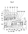
- FIG. 2 is an enlarged view in the vicinity of a first and a second one-way clutch of the power transmission device of FIG. 1 ;
- FIG. 3 is a cross section in a radial direction of a one-way clutch portion of the first one-way clutch.
- FIG. 4 is a cross section in a radial direction of a one-way clutch portion of the second one-way clutch.
- FIG. 1 is a cross section in an axial direction of an example embodiment of the power transmission.
- the power transmission device includes a pulley 3 , a first power-transmitting member 4 , a first one-way clutch 1 , a motor 10 , a rotor 11 , a second one-way clutch 2 and a rotating shaft 6 that is one example of a shaft to drive a compressor.
- the pulley has belt-fitting grooves 3 a in its outer periphery, and a belt (not shown) for transmitting a rotational power of an engine is fitted to the belt-fitting grooves 3 a .
- the pulley 3 transmits the rotational power to the first power-transmitting member 4 , which has an inner peripheral surface 4 a in a radially innermost location of the member 4 .
- a first outer ring 5 of the first one-way clutch 1 is fitted in and fixed to the inner peripheral surface 4 a of the first power-transmitting member 4 , so that the rotational power transmitted from the pulley 3 to the first power-transmitting member 4 is transmitted to the first one-way clutch 1 .
- the first one-way clutch 1 also includes a first inner ring 7 to which the rotational power of the first outer ring 5 is transmitted via first engagement rollers 23 , and the first inner ring 7 is engaged with a thread portion of the rotating shaft 6 in order to be fixed thereto.
- the second one-way clutch 2 has a second outer ring 14 that is fitted in and fixed to an inner peripheral surface 12 a of a yoke 12 of the rotor 11 so that the rotational power of the rotor 11 is transmitted to the second one-way clutch 2 .
- the second one-way clutch 2 further includes a second inner ring 15 to which the rotational power of the second outer ring 14 is transmitted via second engagement rollers 38 .
- An inner peripheral surface of the second inner ring 15 is fitted and fixed around the rotating shaft 6 that drives the compressor.
- FIG. 2 is an enlarged view in the vicinity of the first one-way clutch 1 and the second one-way clutch 2 .
- the first one-way clutch 1 has a one-way clutch portion 50 on the left side thereof as viewed from the front side of this figure, the clutch portion 50 being composed of an engagement cylindrical surface 5 a formed at an inner periphery of the first outer ring 5 , an engagement cam-surface 7 a formed at an outer periphery of the first inner ring 7 , a retainer 22 , coil springs 21 , and the first engagement rollers 23 .
- the first one-way clutch 1 further includes a plurality of first balls 27 and a retainer 26 .
- the first balls 27 retained by the retainer 26 are circumferentially disposed at fixed intervals between a raceway surface 5 b with a circular arc shape in section, which is formed adjacent the engagement cylindrical surface 5 a of the first outer ring 5 , and a raceway surface 7 b with a circular arc shape in section, which is formed adjacent the engagement cam-surface 7 a of the first inner ring 7 .
- the raceway surface 5 b of the first outer ring 5 , the raceway surface 7 b of the first inner ring 7 , the retainer 26 , and the first balls 27 form a deep groove ball bearing portion 55 .
- An axially opened annular recess 67 is provided at the inner periphery of the first inner ring 7 and at a deep-groove-ball-bearing-portion- 55 -side end portion of the first inner ring 7 of the first one-way clutch 1 .
- FIG. 3 is a sectional view in a radial direction of the one-way clutch portion 50 of the first one-way clutch 1 .
- the engagement cam-surface 7 a of the one-way clutch portion 50 at the outer periphery of the first inner ring 7 has a regular polygonal shape in section, as shown in FIG. 3 . Pillar portions that connect two annular frames of the retainer 22 are fitted at apex portions 7 b of the engagement cam-surface 7 a .
- the first engagement rollers 23 disposed in pockets of the retainer 22 are urged in one direction by the associated coil springs 21 .
- the second one-way clutch 2 has a one-way clutch portion 60 on the right side thereof as viewed from the front side of this figure, the clutch portion 60 being composed of an engagement cam-surface 14 a formed at an inner periphery of the second outer ring 14 , an engagement cylindrical surface 15 a formed at an outer periphery of the second inner ring 15 , coil springs not shown, a retainer 37 , and second engagement rollers 38 .
- the second one-way clutch 2 further includes a plurality of second balls 40 and a retainer 39 .
- the second balls 40 retained by the retainer 39 are circumferentially disposed at fixed intervals between a raceway surface 14 b with a circular arc shape in section, which is formed adjacent the engagement cam-surface 14 a of the second outer ring 14 , and a raceway surface 15 b with a circular arc shape in section, which is formed adjacent the engagement cylindrical surface 15 a of the second inner ring 15 .
- the raceway surface 14 b of the second outer ring 14 , the raceway surface 15 b of the second inner ring 15 , the retainer 39 , and the second balls 40 form a deep groove ball bearing portion 65 of the second one-way clutch 2 .
- an end portion on the side of the deep groove ball bearing portion 65 of the second outer ring 14 is disposed in the annular recess 67 formed at the inner periphery of the deep-groove-ball-bearing-portion- 55 -side end portion of the first inner ring 7 .
- the second inner ring 15 is fixed by a bottom surface of the recess 67 of the first inner ring 7 and a riser portion 6 a of the rotating shaft 6 .
- FIG. 4 is a sectional view in a radial direction of the one-way clutch portion 60 of the second one-way clutch 2 .
- the engagement cam-surface 14 a of the one-way clutch portion 60 at the inner periphery of the second outer ring 14 has substantially planar portions at which the second engagement rollers 38 contact the engagement cam-surface 14 a .
- Pillar portions of the retainer 37 connecting opposed annular frames of the retainer 37 are fitted in corresponding annular grooves 14 d with a generally circular arc shape in section, which grooves are provided in the inner peripheral surface of the second outer ring 14 circumferentially at fixed intervals.
- the second engagement rollers 38 individually disposed in respective wedge-shaped pockets of the retainer 37 are urged in one direction by coil springs 41 .
- Reference numerals 91 , 92 , 93 , 94 of FIG. 2 indicate seal members.
- the seal members 91 , 92 seal in grease between the first outer ring 5 and the first inner ring 7
- the seal members 93 , 94 seal in grease between the second outer ring 14 and the second inner ring 15 .
- the rotational power of the engine is transmitted from the first outer ring 5 to the first inner ring 7 . Thereafter, the rotational power of the engine transmitted to the first inner ring 7 is transmitted to the rotating shaft 6 , so that the compressor that is not shown is driven.
- the rotor 11 of the motor 10 is under suspension, i.e., in a non-operational state, when the second engagement rollers 38 of the second one-way clutch 2 are in a loosely fitted state between the engagement cam-surface 14 a of the stationary second outer ring 14 and the engagement cylindrical surface 15 a of the second inner ring 15 rotating forward, namely, the second one-way clutch 2 is in a disengaged state, or off state.
- the engine-driven pulley 3 is stopped, and the first engagement rollers 23 are brought into a loosely fitted state between the engagement cylindrical surface 5 a of the first outer ring 5 that is stationary and the engagement cam-surface 7 a of the first inner ring 7 that is rotating forward, namely the first one-way clutch 1 is brought into a disengaged state.
- the motor 10 is driven to rotate the rotor 11 .
- the rotational power of the rotor 11 is transmitted to the second outer ring 14 of the second one-way clutch 2 , so that the second outer ring 14 is rotated in a forward direction.
- the second one-way clutch 2 is brought into an engaged state, or on state. Consequently, the rotational power is transmitted from the second outer ring 14 to the second inner ring 15 . Then, the rotational power of the rotor 11 transmitted to the second inner ring 15 is transmitted to the rotating shaft 6 and drives the compressor.
- the deep groove ball bearing portions 55 , 65 of the first and second one-way clutches 1 , 2 bear radial loads applied to the one-way clutches 1 , 2 , respectively, to thereby secure load resistance and durability of their respective associated one-way clutch portions 50 , 60 of the one-way clutches 1 , 2 .
- the first one-way clutch 1 is used for transmitting the rotational power of the pulley 3 to the rotating shaft 6
- the second one-way clutch 2 is used for transmitting the rotational power of the rotor 11 of the motor 10 to the rotating shaft 6 . Therefore, the power transmission device of the above embodiment dispenses with an electromagnetic clutch and a control part that controls the on-off operation of the electromagnetic clutch, which are required by the conventional power transmission device. Therefore, the power transmission device can be made simple in structure as well as compact.
- the second one-way clutch 2 is made as a so-called outer cam type one-way clutch in which the engagement cam-surface 14 a is formed at the inner periphery of the outer ring 14 and the engagement cylindrical surface 15 a is formed at the outer periphery of the inner ring 15 .
- a radius of the engagement cylindrical surface 15 a of the second one-way clutch 2 is reduced, as compared with the case where the second one-way clutch 2 is made as a so-called inner cam type one-way clutch in which the engagement cam-surface is formed at the outer periphery of the inner ring, and the engagement cylindrical surface is formed at the inner periphery of the outer ring.
- the first one-way clutch 1 is made as a so-called inner cam type one-way clutch in which the engagement cam-surface 7 a is formed at the outer periphery of the inner ring 7 , and the engagement cylindrical surface 5 a is formed at the inner periphery of the outer ring 5 .
- first one-way clutch 1 When the first one-way clutch 1 is in an engaged state and the first engagement rollers 23 are engaged between the engagement cylindrical surface 5 a of the inner periphery of the outer ring 5 and the engagement cam-surface 7 a of the outer periphery of the inner ring 7 , engagement performance between the first engagement rollers 23 and each of the engagement cylindrical surface 5 a and the engagement cam-surface 7 a is able to be stabilized, compared with the case where the first one-way clutch 1 is made as an outer cam type one-way clutch in which the engagement cam-surface is formed at the inner periphery of the outer ring and the engagement cylindrical surface is formed at the outer periphery of the inner ring.
- the engagement cylindrical surface 5 a is formed at the inner periphery of the outer ring 5 such that the inner periphery of the outer ring 5 is curved, or concave radially outwardly.
- the engagement performance between the engagement cylindrical surface 5 a of the outer ring 5 that is a concave surface and the surfaces of the first engagement rollers 23 that are convex surfaces is improved, compared with the case where the engagement cam-surface is formed at the inner periphery of the outer ring so that the inner periphery of the outer ring is made substantially planar.
- the deep groove ball bearing portions 55 , 65 are provided in the first and second one-way clutches 1 , 2 .
- the associated deep groove ball bearing portion 55 or 65 bear radial loads applied to the associated one-way clutch portion 50 or 60 of the first or second one-way clutch 1 , 2 . Therefore, load resistance and durability of the one-way clutch portions 50 , 60 of the first and second one-way clutch 1 , 2 are favorably secured.
- the first power-transmitting member 4 that transmits the rotational power of the pulley 3 to the first outer ring 5 of the first one-way clutch 1 is provided between the pulley 3 and the first outer ring 5 of the first one-way clutch 1 .
- the rotational power of the pulley may directly be transmitted to the outer ring of the first one-way clutch.
- the yoke 12 of the rotor 11 is directly connected to the second outer ring 14 of the second one-way clutch 2 , so that the rotational power of the rotor 11 is directly transmitted to the second outer ring 14 .
- an additional power-transmitting member may be inserted between the rotor and the second outer ring of the second one-way clutch so that the rotational power of the rotor is transmitted to the second outer ring of the second one-way clutch via the additional power transmitting member.
- the deep groove ball bearing portions 55 , 65 are individually provided in the first one-way clutch 1 and the second one-way clutch 2 . According to the present invention, either or both of the deep groove ball bearing portions 55 , 65 may be omitted.
- the engagement cylindrical surface 5 a is formed on the inner peripheral surface of the first outer ring 5 of the first one-way clutch 1 that transmits the rotational power of the engine-driven pulley 3 to the rotating shaft 6 that drives the compressor, and the engagement cam-surface 7 a is formed on the outer periphery of the first inner ring 7 , whereby the first one-way clutch 1 is made as the so-called inner cam type one-way clutch using the engagement rollers as the engagement members.
- the first one-way clutch may also be a sprag clutch using sprags as the engagement members.
- the deep groove ball bearing portion 55 of the first one-way clutch 1 is disposed in the right-hand side location of the first one-way clutch 1 in FIG. 2 , but may be disposed in a left-hand side location of the first one-way clutch in FIG. 2 .
- the deep groove ball bearing portion 65 of the second one-way clutch 2 is disposed in the left side location of the second one-way clutch 2 in FIG. 2 , but may be disposed in a right-hand side location of the second one-way clutch 2 in FIG. 2 .
- the deep groove ball bearing portions are provided in the first and second one-way clutches 1 , 2 .
- an angular ball bearing portion or a four-point contact ball bearing portion may be provided in at least one of the first and second one-way clutches.
Landscapes
- Engineering & Computer Science (AREA)
- General Engineering & Computer Science (AREA)
- Mechanical Engineering (AREA)
- Pulleys (AREA)
- Connection Of Motors, Electrical Generators, Mechanical Devices, And The Like (AREA)
- Compressors, Vaccum Pumps And Other Relevant Systems (AREA)
Abstract
Description
Claims (3)
Applications Claiming Priority (2)
| Application Number | Priority Date | Filing Date | Title |
|---|---|---|---|
| JP2003-53757 | 2003-02-28 | ||
| JP2003053757A JP4158556B2 (en) | 2003-02-28 | 2003-02-28 | Power transmission device |
Publications (2)
| Publication Number | Publication Date |
|---|---|
| US20040180742A1 US20040180742A1 (en) | 2004-09-16 |
| US7278938B2 true US7278938B2 (en) | 2007-10-09 |
Family
ID=32767852
Family Applications (1)
| Application Number | Title | Priority Date | Filing Date |
|---|---|---|---|
| US10/786,618 Expired - Fee Related US7278938B2 (en) | 2003-02-28 | 2004-02-26 | Power transmission device |
Country Status (4)
| Country | Link |
|---|---|
| US (1) | US7278938B2 (en) |
| EP (1) | EP1452777B1 (en) |
| JP (1) | JP4158556B2 (en) |
| DE (1) | DE602004016069D1 (en) |
Cited By (1)
| Publication number | Priority date | Publication date | Assignee | Title |
|---|---|---|---|---|
| US20090229945A1 (en) * | 2008-03-12 | 2009-09-17 | Koji Sato | Rotation transmission device |
Families Citing this family (6)
| Publication number | Priority date | Publication date | Assignee | Title |
|---|---|---|---|---|
| JP4161741B2 (en) * | 2003-02-28 | 2008-10-08 | 株式会社ジェイテクト | One-way clutch unit |
| CN103477119B (en) * | 2011-04-11 | 2016-03-02 | 利滕斯汽车合伙公司 | For by transmission of power to the multi-speed transmission of load |
| US9791001B2 (en) * | 2012-12-27 | 2017-10-17 | Toyota Jidosha Kabushiki Kaisha | Power transmitting apparatus for vehicle |
| CN105190073A (en) * | 2013-04-23 | 2015-12-23 | 爱信艾达株式会社 | One-way clutch device |
| CN103633774A (en) * | 2013-11-07 | 2014-03-12 | 大连华根机械有限公司 | Unloading mechanism |
| US9097297B1 (en) * | 2014-01-17 | 2015-08-04 | Gates Corporation | Hydraulic isolator decoupler |
Citations (19)
| Publication number | Priority date | Publication date | Assignee | Title |
|---|---|---|---|---|
| JPH0560153A (en) * | 1991-08-30 | 1993-03-09 | Koyo Seiko Co Ltd | One-way clutch |
| JPH1193876A (en) | 1997-07-24 | 1999-04-06 | Denso Corp | Combined compression device |
| JP2000274456A (en) * | 1999-03-23 | 2000-10-03 | Koyo Seiko Co Ltd | One-way clutch |
| JP2001032907A (en) | 1999-07-19 | 2001-02-06 | Ogura Clutch Co Ltd | Power transmission device |
| JP2001140757A (en) | 1999-11-12 | 2001-05-22 | Zexel Valeo Climate Control Corp | Hybrid compressor |
| US6234769B1 (en) * | 1997-07-09 | 2001-05-22 | Denso Corporation | Hybrid type compressor driven by engine and electric motor |
| EP1243448A1 (en) | 2001-03-19 | 2002-09-25 | Kabushiki Kaisha Toyota Jidoshokki | Vehicular air conditioner compressor |
| US20020157413A1 (en) * | 2001-04-24 | 2002-10-31 | Shigeki Iwanami | Compressor driven selectively by first and second drive sources |
| US20030017899A1 (en) | 2001-07-23 | 2003-01-23 | Hideki Fujiwara | Driving force transmission apparatus |
| EP1316452A2 (en) | 2001-11-29 | 2003-06-04 | Kabushiki Kaisha Toyota Jidoshokki | Vehicular rotational apparatus |
| US20030103848A1 (en) * | 2001-11-29 | 2003-06-05 | Hirohito Hayashi | Rotary machine for vehicle |
| US20030141161A1 (en) * | 2000-07-03 | 2003-07-31 | Hideo Ouchi | One-way clutch built-in type pulley device |
| US6640948B2 (en) * | 2001-07-19 | 2003-11-04 | Nsk-Warner K.K. | One-way clutch apparatus |
| DE10317522A1 (en) * | 2002-04-25 | 2003-11-06 | Denso Corp | Composite add-on machine for a vehicle and control unit therefor |
| US20040178040A1 (en) | 2003-02-28 | 2004-09-16 | Koyo Seiko Co., Ltd. | One-way clutch unit |
| US6993910B2 (en) * | 2003-06-17 | 2006-02-07 | Denso Corporation | Fluid machine |
| US7007781B2 (en) * | 2003-02-28 | 2006-03-07 | Koyo Seiko Co., Ltd. | One-way clutch unit and one-way clutch therefor |
| US7056247B2 (en) | 2000-07-27 | 2006-06-06 | Koyo Seiko Co., Ltd. | Pulley unit |
| US7143881B2 (en) | 2001-10-02 | 2006-12-05 | Koyo Seiko Co., Ltd. | Pulley unit having one-way clutch |
-
2003
- 2003-02-28 JP JP2003053757A patent/JP4158556B2/en not_active Expired - Fee Related
-
2004
- 2004-02-26 US US10/786,618 patent/US7278938B2/en not_active Expired - Fee Related
- 2004-02-27 EP EP04004490A patent/EP1452777B1/en not_active Expired - Lifetime
- 2004-02-27 DE DE602004016069T patent/DE602004016069D1/en not_active Expired - Lifetime
Patent Citations (20)
| Publication number | Priority date | Publication date | Assignee | Title |
|---|---|---|---|---|
| JPH0560153A (en) * | 1991-08-30 | 1993-03-09 | Koyo Seiko Co Ltd | One-way clutch |
| US6234769B1 (en) * | 1997-07-09 | 2001-05-22 | Denso Corporation | Hybrid type compressor driven by engine and electric motor |
| JPH1193876A (en) | 1997-07-24 | 1999-04-06 | Denso Corp | Combined compression device |
| JP2000274456A (en) * | 1999-03-23 | 2000-10-03 | Koyo Seiko Co Ltd | One-way clutch |
| JP2001032907A (en) | 1999-07-19 | 2001-02-06 | Ogura Clutch Co Ltd | Power transmission device |
| JP2001140757A (en) | 1999-11-12 | 2001-05-22 | Zexel Valeo Climate Control Corp | Hybrid compressor |
| US20030141161A1 (en) * | 2000-07-03 | 2003-07-31 | Hideo Ouchi | One-way clutch built-in type pulley device |
| US7056247B2 (en) | 2000-07-27 | 2006-06-06 | Koyo Seiko Co., Ltd. | Pulley unit |
| EP1243448A1 (en) | 2001-03-19 | 2002-09-25 | Kabushiki Kaisha Toyota Jidoshokki | Vehicular air conditioner compressor |
| US20020157413A1 (en) * | 2001-04-24 | 2002-10-31 | Shigeki Iwanami | Compressor driven selectively by first and second drive sources |
| US6640948B2 (en) * | 2001-07-19 | 2003-11-04 | Nsk-Warner K.K. | One-way clutch apparatus |
| US20030017899A1 (en) | 2001-07-23 | 2003-01-23 | Hideki Fujiwara | Driving force transmission apparatus |
| US7143881B2 (en) | 2001-10-02 | 2006-12-05 | Koyo Seiko Co., Ltd. | Pulley unit having one-way clutch |
| US20030103848A1 (en) * | 2001-11-29 | 2003-06-05 | Hirohito Hayashi | Rotary machine for vehicle |
| US6617727B2 (en) * | 2001-11-29 | 2003-09-09 | Kabushiki Kaisha Toyota Jidoshokki | Vehicular rotational apparatus |
| EP1316452A2 (en) | 2001-11-29 | 2003-06-04 | Kabushiki Kaisha Toyota Jidoshokki | Vehicular rotational apparatus |
| DE10317522A1 (en) * | 2002-04-25 | 2003-11-06 | Denso Corp | Composite add-on machine for a vehicle and control unit therefor |
| US20040178040A1 (en) | 2003-02-28 | 2004-09-16 | Koyo Seiko Co., Ltd. | One-way clutch unit |
| US7007781B2 (en) * | 2003-02-28 | 2006-03-07 | Koyo Seiko Co., Ltd. | One-way clutch unit and one-way clutch therefor |
| US6993910B2 (en) * | 2003-06-17 | 2006-02-07 | Denso Corporation | Fluid machine |
Cited By (2)
| Publication number | Priority date | Publication date | Assignee | Title |
|---|---|---|---|---|
| US20090229945A1 (en) * | 2008-03-12 | 2009-09-17 | Koji Sato | Rotation transmission device |
| US8272487B2 (en) * | 2008-03-12 | 2012-09-25 | Ntn Corporation | Rotation transmission device |
Also Published As
| Publication number | Publication date |
|---|---|
| US20040180742A1 (en) | 2004-09-16 |
| JP4158556B2 (en) | 2008-10-01 |
| EP1452777A3 (en) | 2006-01-18 |
| JP2004263760A (en) | 2004-09-24 |
| DE602004016069D1 (en) | 2008-10-09 |
| EP1452777A2 (en) | 2004-09-01 |
| EP1452777B1 (en) | 2008-08-27 |
Similar Documents
| Publication | Publication Date | Title |
|---|---|---|
| US6893368B2 (en) | Driving force transmission apparatus | |
| JPH11153207A (en) | Torque converter | |
| US7278938B2 (en) | Power transmission device | |
| US6655516B2 (en) | Concentrically arranged pulley and shaft with one-way clutch | |
| US5575366A (en) | Vehicular charging generator | |
| US20020014073A1 (en) | Stator support structure for torque converter | |
| US7007781B2 (en) | One-way clutch unit and one-way clutch therefor | |
| JPH11230012A (en) | Auxiliary drive using starter motor | |
| EP1452355B1 (en) | One-way clutch unit | |
| JP4111556B2 (en) | High speed pulley unit for engine auxiliary equipment | |
| JP2006097710A (en) | One-way clutch | |
| JP2006009899A (en) | Power transmission | |
| US6422371B1 (en) | Centrifugal friction clutch for automatic transmission | |
| US20080190728A1 (en) | One-way clutch | |
| US5355982A (en) | Starter drive for internal combustion engines | |
| JP4617610B2 (en) | Pulley unit | |
| JP2008008410A (en) | Pulley unit | |
| JP2005214312A (en) | One-way clutch assembly with thrust roller bearing | |
| JP2006258247A (en) | Pulley unit | |
| JP2012145216A (en) | Pulley unit | |
| JP5112722B2 (en) | One-way clutch | |
| JP2009008197A (en) | One-way clutch | |
| JP2001090810A (en) | Pulley unit and one-way clutch used therefor | |
| JP2008032130A (en) | One-way clutch | |
| JP2005226720A (en) | One-way clutch unit and power transmission |
Legal Events
| Date | Code | Title | Description |
|---|---|---|---|
| AS | Assignment |
Owner name: KOYO SEIKO CO., LTD., JAPAN Free format text: ASSIGNMENT OF ASSIGNORS INTEREST;ASSIGNORS:ICHIHARA, TAKAHIRO;WATANABE, HAJIME;FUJIWARA, HIDEKI;AND OTHERS;REEL/FRAME:015362/0972;SIGNING DATES FROM 20040319 TO 20040331 Owner name: KABUSHIKI KAISHA TOYOTA JIDOSHOKKI, JAPAN Free format text: ASSIGNMENT OF ASSIGNORS INTEREST;ASSIGNORS:ICHIHARA, TAKAHIRO;WATANABE, HAJIME;FUJIWARA, HIDEKI;AND OTHERS;REEL/FRAME:015362/0972;SIGNING DATES FROM 20040319 TO 20040331 |
|
| AS | Assignment |
Owner name: KOYO SEIKO CO., LTD., JAPAN Free format text: ASSIGNMENT OF ASSIGNORS INTEREST;ASSIGNOR:JIDOSHOKKI, KABUSHIKI KAISHA TOYOTA;REEL/FRAME:017352/0990 Effective date: 20051206 |
|
| AS | Assignment |
Owner name: JTEKT CORPORATION,JAPAN Free format text: CHANGE OF NAME;ASSIGNOR:KOYO SEIKO CO., LTD.;REEL/FRAME:018992/0365 Effective date: 20060101 Owner name: JTEKT CORPORATION, JAPAN Free format text: CHANGE OF NAME;ASSIGNOR:KOYO SEIKO CO., LTD.;REEL/FRAME:018992/0365 Effective date: 20060101 |
|
| FEPP | Fee payment procedure |
Free format text: PAYOR NUMBER ASSIGNED (ORIGINAL EVENT CODE: ASPN); ENTITY STATUS OF PATENT OWNER: LARGE ENTITY |
|
| FPAY | Fee payment |
Year of fee payment: 4 |
|
| REMI | Maintenance fee reminder mailed | ||
| LAPS | Lapse for failure to pay maintenance fees | ||
| STCH | Information on status: patent discontinuation |
Free format text: PATENT EXPIRED DUE TO NONPAYMENT OF MAINTENANCE FEES UNDER 37 CFR 1.362 |
|
| STCH | Information on status: patent discontinuation |
Free format text: PATENT EXPIRED DUE TO NONPAYMENT OF MAINTENANCE FEES UNDER 37 CFR 1.362 |
|
| FP | Lapsed due to failure to pay maintenance fee |
Effective date: 20151009 |