US7277779B2 - Real-time emergency control in power systems - Google Patents
Real-time emergency control in power systems Download PDFInfo
- Publication number
- US7277779B2 US7277779B2 US10/870,160 US87016004A US7277779B2 US 7277779 B2 US7277779 B2 US 7277779B2 US 87016004 A US87016004 A US 87016004A US 7277779 B2 US7277779 B2 US 7277779B2
- Authority
- US
- United States
- Prior art keywords
- trajectory
- input control
- real
- control
- different
- Prior art date
- Legal status (The legal status is an assumption and is not a legal conclusion. Google has not performed a legal analysis and makes no representation as to the accuracy of the status listed.)
- Expired - Fee Related, expires
Links
Images


Classifications
-
- G—PHYSICS
- G05—CONTROLLING; REGULATING
- G05B—CONTROL OR REGULATING SYSTEMS IN GENERAL; FUNCTIONAL ELEMENTS OF SUCH SYSTEMS; MONITORING OR TESTING ARRANGEMENTS FOR SUCH SYSTEMS OR ELEMENTS
- G05B13/00—Adaptive control systems, i.e. systems automatically adjusting themselves to have a performance which is optimum according to some preassigned criterion
- G05B13/02—Adaptive control systems, i.e. systems automatically adjusting themselves to have a performance which is optimum according to some preassigned criterion electric
- G05B13/04—Adaptive control systems, i.e. systems automatically adjusting themselves to have a performance which is optimum according to some preassigned criterion electric involving the use of models or simulators
- G05B13/048—Adaptive control systems, i.e. systems automatically adjusting themselves to have a performance which is optimum according to some preassigned criterion electric involving the use of models or simulators using a predictor
-
- H—ELECTRICITY
- H02—GENERATION; CONVERSION OR DISTRIBUTION OF ELECTRIC POWER
- H02J—ELECTRIC POWER NETWORKS; CIRCUIT ARRANGEMENTS OR SYSTEMS FOR SUPPLYING OR DISTRIBUTING ELECTRIC POWER; SYSTEMS FOR STORING ELECTRIC ENERGY
- H02J3/00—Circuit arrangements for AC mains or AC distribution networks
- H02J3/001—Arrangements for handling faults or abnormalities, e.g. emergencies or contingencies
- H02J3/0012—Arrangements for handling faults or abnormalities, e.g. emergencies or contingencies characterised by the contingency detection means in AC networks, e.g. using phasor measurement units [PMU], synchrophasors or contingency analysis
Definitions
- the invention relates to power systems such as electric power transmission networks. It is concerned with a real-time method for controlling emergencies in the power system.
- Electric power transmission and distribution systems or networks comprise high-voltage tie lines for connecting geographically separated regions, medium-voltage lines, and substations for transforming voltages and for switching connections between lines.
- For managing the network it is desirable to determine a state of the network, in particular load flows and stability margins.
- RMS root mean square
- devices and systems for measuring voltage and current phasors at different locations of a network at exactly the same time have become available.
- PMU Phasor Measurement Unit
- the evolution in time of the overall state of the power system or a particular physical system quantity, such as the voltage at a certain node of a transmission network, is represented by a one—or multidimensional trajectory. Based on the current state of the system and taking into account potential control actions applied to the system, a future progression of the trajectory may be calculated.
- Model Predictive Control MPC
- MPC is an academically and industrially well-known and accepted method for process control. The main principle can be seen from FIG. 1 .
- a system model representing e.g. a real power system and taking into account its dynamics, is used to predict output trajectories (x i ) based on the current state at time t 0 and for several different potential candidate input sequences ( ⁇ x i ).
- a cost function is then defined based on the deviation of each predicted trajectory from a desired reference trajectory (x ref ) over a window in time called the prediction interval (t p ).
- the optimal control in the sense that it minimizes the defined cost function, is then obtained by solving an optimization problem.
- MPC multi-dimensional predictive coding
- a prediction stage which results in an approximation of the output trajectories for a certain input sequence. For linear systems this can be done by a number of matrix multiplications but for nonlinear systems this is usually done by simulation.
- a decision stage which typically consists of minimizing or maximizing a numerical performance objective which is based on the deviations of the trajectory approximation from a desired reference trajectory.
- Different methods have been applied such as linear/quadratic programming, nonlinear optimization or heuristic tree-search techniques. They all have in common that they require a large number of iterations, that is, evaluations of the cost criterion, which makes the computational burden of model-predictive control for large-scale nonlinear systems unattractive.
- trajectory sensitivities have been developed with the purpose of reducing the computational burden when the evaluation of multiple trajectories is necessary. Instead of evaluating all trajectories individually, only one trajectory is evaluated using a modified simulation method where the sensitivities with respect to key parameters are noted and approximations of the trajectories for such parameter changes can be made in a computationally efficient manner.
- the sensitivities of trajectories to initial conditions and/or parameters do provide an insight into the behaviour of a dynamic power system, as is described e.g. in the article by I. A. Hiskens and M. A. Pai, “Trajectory Sensitivity Analysis of Hybrid Systems”, IEEE Trans. Circuits and Systems, vol. 47, pp. 204-220, 2000.
- these capabilities of trajectory sensitivities have so far mainly been used for post-mortem analysis of a collapsed power system.
- the dependency of a trajectory of the power system on possible corrective measures or input control actions is analysed and an optimum control action is identified and applied to the system.
- the standard prediction stage in model predictive control is replaced with the evaluation of only one nominal trajectory, along which the system would evolve without any corrective input, together with its corresponding trajectory sensitivities.
- the rest of the trajectories that need to be evaluated during the traditional decision stage are then approximated using the nominal trajectory and the sensitivities instead of using a full simulation for each trajectory.
- the time dependence of the sensitivities even allows to properly reproduce a dynamic behaviour of the power system.
- the detection of an incipient instability acts as a trigger for the corrective measures or processes. It preferably comprises the detection or notification of a contingency such as the discontinuous opening or closing of a switch, i.e. a change in the network topology, or a load increase or a generator rejection.
- a contingency such as the discontinuous opening or closing of a switch, i.e. a change in the network topology, or a load increase or a generator rejection.
- the last recorded system state preceding the contingency serves as an initial point for prediction of the nominal trajectory during the subsequent calculations.
- no corrective input or preventive action is applied to the power system as long as the nominal trajectory remains within acceptable trajectory limits, at least up to the time horizon of the prediction interval.
- the identification of an optimum input control action preferably comprises the evaluation of a cost function which quantifies the difference between an output trajectory and a reference trajectory.
- the latter represents a target state for the trajectory, deviations therefrom are penalized.
- too crude corrective measures resulting in load shedding and adversely affecting customers may be considered disadvantageous.
- control inputs are assumed constant over the prediction interval, thus further simplifying calculations compared to the case of controls varying in time.
- the chosen optimum input control may be adapted should the occurrence of a further contingency during the initial prediction horizon make it necessary.
- control inputs may take on only discrete values such as tap positions, or are applicable only in discontinuous portions
- Mixed Dynamic Logic MDL is used to handle both continuous and discontinuous controls within the same model.
- FIG. 1 illustrates state of the art model predictive control (MPC)
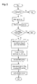
- FIG. 2 is a flowchart outlining the basic principles
- FIG. 3 depicts the effects of a real-time control on a trajectory
- FIG. 4 shows three trajectories representing three different nodes of a real power system.
- FIG. 2 shows the structure of the method in the form of a flowchart.
- a contingency can be quickly detected and the state of the system accurately estimated using e.g. a wide-area measurement system.
- the data coming from the state estimator in this case are voltage and current phasors, which are processed to obtain the initial state of the system, generally denoted x 0 .
- the contingency is detected at time t c .
- the prediction takes the values one step back, at time t 0 , as the initial state x 0 .
- a nominal trajectory x nom of the system corresponding e.g. to a post-fault voltage, is predicted.
- the nominal trajectory takes into account the known contingency at t c , but assumes no further disturbances or modifications to be applied to the system.
- the earliest time for evaluating the effect of a control will be at t a (it is assumed that the time delay t a ⁇ t c is known).
- t a the nominal trajectory x nom is checked for consistency with a predefined tolerance band (x max ⁇ x min ), and as long as x nom is predicted to lie within the acceptable tolerance band, no corrective action is applied.
- the tolerance band can be wider in the beginning to allow for larger excursions of the post-fault voltage mentioned.
- the voltage typically has to recover to the normal operation range before a local under-voltage relay protection would act at time t uvls .
- the sampling time i.e. the time t c ⁇ t 0 between to successive checks for contingency, may be 1 s, whereas the time delay t a ⁇ t c may be less, e.g. 300 ms.
- trajectory sensitivities calculations start. Because the corrective or input action is executed at or before time t a , the trajectory sensitivities are computed with respect to the values x a expected at that time t a (available from nominal trajectory calculation) as well as for later integration time steps. In contrast to the traditional MPC, where a sequence of control inputs is determined, constant control inputs, which remain the same for the whole prediction horizon, are evaluated here.
- the lower graph of FIG. 3 represents two constant control inputs first applied at t a , i.e. a change of a tap position dn and a load shedding factor k. The correction resulted in the trajectory denoted x cor .
- Power systems dynamics can be modeled, taking into account their hybrid nature (combination of continuous and discrete dynamics), as follows:
- x are the dynamic or continuous states (generators angles, generator rotor velocities, magnetic fluxes)
- z represents discrete states (e.g. tap positions of transformers)
- ⁇ represents parameters (for example line impedances)
- y represents algebraic states (such as voltages).
- ⁇ ⁇ ⁇ x _ ⁇ ( t ) ⁇ x _ ⁇ ( t ) ⁇ x _ 0 ⁇ ⁇ ⁇ ⁇ x _ 0 + higher ⁇ ⁇ order ⁇ ⁇ terms ⁇ x _ x _ 0 ⁇ ( t ) ⁇ ⁇ ⁇ ⁇ x _ 0
- Differentiations with respect to the initial conditions and parameters yields:
- Each diagonal element is actually a row vector corresponding to the discrete values of one particular control, e.g. all possible tap positions of one tap changing transformer.
- ⁇ is a column vector of auxiliary binary variables (they can be either 1 or 0) consisting of sub-vectors corresponding to the C elements.
- the sought result of the optimization procedure becomes vector ⁇ , where all elements will be zero except the ones filled with one, pointing at the needed control input.
- new constraints have to be taken into account.
- the inclusion of equality constraints is necessary when there is a tight connection/relation between some controls, e.g. load shedding of active and reactive power being physically coupled.
- the inventive method has been applied to model system inspired by a real power transmission system which is very sensitive to outages of lines interconnecting two geographically separated areas.
- the possible controls considered are a) tap changer of a transformer between two nodes where the largest load is connected, b) load shedding of all available loads, and c) change of the voltage reference point setting of the generators voltage regulators.
- the last mentioned type of control allows utilizing of unused reactive power generation capacities (if they are available, i.e. the generators are not operated on their limits) and thus keeping the system voltage profile on the acceptable level. Since the load shedding should be used only as a last measure, if absolutely necessary, the penalties for employed controls (elements of parameter R in the cost function) have been set accordingly.
- the most desired control to be used is tap-changing, then setting of the generators reference points and finally load shedding. Note, that the penalties can vary within each category.
- the simulated contingency is the tripping of two lines which would result in a drop of the voltage in several locations/nodes, represented by the three trajectories x1, x2 and x3, under the allowed level.
- employing the four different proposed controls as shown in the bottom graph of FIG. 4 safely stabilizes the situation (top graph).
- the emphasis is given on the accurate control, i.e. the weight Q is dominant over the weight R, which results in heavy engagement of the control mechanisms, especially load shedding as represented by the factor k.
- the focus is more on being within the acceptable operation range, rather than to achieve certain exact (optimal) voltages, and to employ as little expensive controls (load shedding) as possible.
Landscapes
- Engineering & Computer Science (AREA)
- General Physics & Mathematics (AREA)
- Health & Medical Sciences (AREA)
- Computer Vision & Pattern Recognition (AREA)
- Evolutionary Computation (AREA)
- Medical Informatics (AREA)
- Software Systems (AREA)
- Artificial Intelligence (AREA)
- Automation & Control Theory (AREA)
- Physics & Mathematics (AREA)
- Power Engineering (AREA)
- Supply And Distribution Of Alternating Current (AREA)
- Feedback Control In General (AREA)
- Stand-By Power Supply Arrangements (AREA)
- Alarm Systems (AREA)
- Absorbent Articles And Supports Therefor (AREA)
Abstract
Description
with the vectors
where x are the dynamic or continuous states (generators angles, generator rotor velocities, magnetic fluxes), z represents discrete states (e.g. tap positions of transformers), λ represents parameters (for example line impedances) and y represents algebraic states (such as voltages). The flow of the system can be written:
Sensitivities of the system flow to the initial conditions and parameters are obtained by a Taylor expansion of above equation:
Differentiations with respect to the initial conditions and parameters yields:
The initial trajectory sensitivities values are then:
Applying a trapezoidal integration method, a numerical expression for the computation of the time dependent trajectory sensitivities
at any time instant k+1 can be derived.
Since Δxαrepresents the control inputs, the objective function of MPC is:
where the sensitivity vector contains only the relevant entries (corresponding to the manipulated control inputs) for the whole prediction horizon (i.e. for all sample times starting at tα). The constraints on the system states (here voltages) are:
and on the control variables:
Δxαmin≦Δxα≦xαmax.
Δxα=C.δ
where C is the diagonal matrix containing values of available controls. Each diagonal element is actually a row vector corresponding to the discrete values of one particular control, e.g. all possible tap positions of one tap changing transformer. δ is a column vector of auxiliary binary variables (they can be either 1 or 0) consisting of sub-vectors corresponding to the C elements. Thus the sought result of the optimization procedure becomes vector δ, where all elements will be zero except the ones filled with one, pointing at the needed control input. To guarantee that only one control will be chosen per control object (e.g. only one out of the possible tap positions can be used), new constraints have to be taken into account. In addition, the inclusion of equality constraints is necessary when there is a tight connection/relation between some controls, e.g. load shedding of active and reactive power being physically coupled.
- Δxainput control action
- xnom nominal trajectory
- xref reference trajectory
- xcor corrected trajectory
Claims (8)
Applications Claiming Priority (2)
| Application Number | Priority Date | Filing Date | Title |
|---|---|---|---|
| EP03405451A EP1489715B1 (en) | 2003-06-21 | 2003-06-21 | Real-time emergency control in power systems |
| EP03405451.0 | 2003-06-21 |
Publications (2)
| Publication Number | Publication Date |
|---|---|
| US20050099747A1 US20050099747A1 (en) | 2005-05-12 |
| US7277779B2 true US7277779B2 (en) | 2007-10-02 |
Family
ID=33396096
Family Applications (1)
| Application Number | Title | Priority Date | Filing Date |
|---|---|---|---|
| US10/870,160 Expired - Fee Related US7277779B2 (en) | 2003-06-21 | 2004-06-18 | Real-time emergency control in power systems |
Country Status (6)
| Country | Link |
|---|---|
| US (1) | US7277779B2 (en) |
| EP (1) | EP1489715B1 (en) |
| AT (1) | ATE428207T1 (en) |
| DE (1) | DE60327058D1 (en) |
| ES (1) | ES2325685T3 (en) |
| SI (1) | SI1489715T1 (en) |
Cited By (8)
| Publication number | Priority date | Publication date | Assignee | Title |
|---|---|---|---|---|
| US20080052059A1 (en) * | 2006-08-22 | 2008-02-28 | Korea Electrotechnology Research Institute | Intelligent System and Method for Monitoring Generator Reactive Power Limit Using Machine Model Parameters |
| US20090009349A1 (en) * | 2007-07-02 | 2009-01-08 | Areva T&D Uk Limited | Method of determining voltage stability margin for load shedding within an electrical power system |
| US20090069950A1 (en) * | 2004-04-19 | 2009-03-12 | Canon Kabushiki Kaisha | Electric power control apparatus, power generation system and power grid system |
| US20090240480A1 (en) * | 2008-03-19 | 2009-09-24 | Honeywell International Inc. | Target trajectory generator for predictive control of nonlinear systems using extended kalman filter |
| US20100161146A1 (en) * | 2008-12-23 | 2010-06-24 | International Business Machines Corporation | Variable energy pricing in shortage conditions |
| US20110282507A1 (en) * | 2008-12-03 | 2011-11-17 | Abb Research Ltd | Method and apparatus for adapting at least one set of parameters of an intelligent electronic device |
| CN102445660A (en) * | 2011-09-27 | 2012-05-09 | 河海大学 | Generator Power Angle Prediction Method Based on Gray Verhulst Model |
| US9887531B2 (en) * | 2013-08-23 | 2018-02-06 | Abb Research Ltd | Adaptive protection for distribution grid based on area concept |
Families Citing this family (12)
| Publication number | Priority date | Publication date | Assignee | Title |
|---|---|---|---|---|
| US8588993B2 (en) * | 2008-11-05 | 2013-11-19 | Abb Research Ltd. | Voltage regulation optimization |
| CN102156261B (en) * | 2011-03-23 | 2013-02-06 | 西安交通大学 | Device and method for predicating angle on basis of high-order state information of generator |
| BR112015018424A2 (en) * | 2013-02-26 | 2017-07-18 | Schweitzer Engineering Lab Inc | system for predicting state trajectory in an electrical dispensing system, and method for predicting state trajectory in an electrical dispensing system |
| US10333312B2 (en) | 2013-06-26 | 2019-06-25 | Schweitzer Engineering Laboratories, Inc. | Distributed control in electric power delivery systems |
| CN103840453B (en) * | 2014-03-06 | 2016-03-09 | 国家电网公司 | Electrical network is promptly rationed the power supply the method for risk emergency flight control |
| US9823637B2 (en) * | 2014-09-05 | 2017-11-21 | Southern States, Llc | Fault detection and isolation using a common reference clock |
| CN108767876B (en) * | 2018-05-31 | 2021-09-17 | 大连理工大学 | Active frequency response model prediction control method for large power grid |
| US10931109B2 (en) * | 2019-01-10 | 2021-02-23 | Schweitzer Engineering Laboratories, Inc. | Contingency based load shedding system for both active and reactive power |
| US11846959B2 (en) * | 2021-01-13 | 2023-12-19 | Whirlpool Corporation | Household energy management system utilizing multiple scales of time |
| CN113422377B (en) * | 2021-08-25 | 2021-11-09 | 中国电力科学研究院有限公司 | DC modulation and secondary frequency modulation coordinated optimization configuration method and device |
| CN114094595A (en) * | 2021-11-19 | 2022-02-25 | 西安交通大学 | Direct-current cluster near-zone voltage recovery control method based on multi-station voltage track sensitivity |
| CN118801392A (en) * | 2024-07-09 | 2024-10-18 | 南京理工大学 | Voltage optimization strategy based on improved sensitivity coefficient and model predictive control |
Citations (7)
| Publication number | Priority date | Publication date | Assignee | Title |
|---|---|---|---|---|
| US4055795A (en) * | 1976-07-15 | 1977-10-25 | H.O.P. Consulab Inc. | Correction system for regulating the power factor of an electrical network |
| US4425541A (en) * | 1981-09-14 | 1984-01-10 | Commonwealth Edison Co. | Apparatus for identifying defective electric power distribution capacitors |
| US4623884A (en) * | 1983-08-11 | 1986-11-18 | Sumitomo Electric Industries, Ltd. | Transmission line control system with by-pass control |
| WO1990015369A1 (en) | 1989-06-05 | 1990-12-13 | The University Of Newcastle Research Associates Limited | A controller for a system |
| US5387821A (en) * | 1992-11-12 | 1995-02-07 | Allegro Microsystems, Inc. | Power distribution circuit with power factor correction and independent harmonic current filter |
| US5698969A (en) * | 1995-11-29 | 1997-12-16 | Westinghouse Electric Corporation | Apparatus and method for interline power flow control |
| US5745368A (en) | 1996-03-29 | 1998-04-28 | Siemens Energy & Automation, Inc. | Method for voltage stability analysis of power systems |
-
2003
- 2003-06-21 ES ES03405451T patent/ES2325685T3/en not_active Expired - Lifetime
- 2003-06-21 SI SI200331621T patent/SI1489715T1/en unknown
- 2003-06-21 AT AT03405451T patent/ATE428207T1/en not_active IP Right Cessation
- 2003-06-21 DE DE60327058T patent/DE60327058D1/en not_active Expired - Lifetime
- 2003-06-21 EP EP03405451A patent/EP1489715B1/en not_active Expired - Lifetime
-
2004
- 2004-06-18 US US10/870,160 patent/US7277779B2/en not_active Expired - Fee Related
Patent Citations (7)
| Publication number | Priority date | Publication date | Assignee | Title |
|---|---|---|---|---|
| US4055795A (en) * | 1976-07-15 | 1977-10-25 | H.O.P. Consulab Inc. | Correction system for regulating the power factor of an electrical network |
| US4425541A (en) * | 1981-09-14 | 1984-01-10 | Commonwealth Edison Co. | Apparatus for identifying defective electric power distribution capacitors |
| US4623884A (en) * | 1983-08-11 | 1986-11-18 | Sumitomo Electric Industries, Ltd. | Transmission line control system with by-pass control |
| WO1990015369A1 (en) | 1989-06-05 | 1990-12-13 | The University Of Newcastle Research Associates Limited | A controller for a system |
| US5387821A (en) * | 1992-11-12 | 1995-02-07 | Allegro Microsystems, Inc. | Power distribution circuit with power factor correction and independent harmonic current filter |
| US5698969A (en) * | 1995-11-29 | 1997-12-16 | Westinghouse Electric Corporation | Apparatus and method for interline power flow control |
| US5745368A (en) | 1996-03-29 | 1998-04-28 | Siemens Energy & Automation, Inc. | Method for voltage stability analysis of power systems |
Non-Patent Citations (7)
| Title |
|---|
| D. Rerkpreedapong et al., "Economy Oriented Model Predictive Load Frequency Control", Lescope'03, Large Engineering Systems Conference on power Engineering, Conference Proceedings, Montreal, Quebec, Canada May 7-9, 2003, pp. 12-16. |
| D.G. Hart et al., "PMUs-A new approach to power network monitoring", ABB Review Jan. 2001, pp. 58-61. |
| I.A. Hiskens et al., "Power System Applications of Trajectory Sensitivities", 2002 IEEE Power Engineering Society, Winter Meeting, Conference Proceedings, New York, NY, Jan. 27-31, 2002, vol. 2, pp. 1200-1205. |
| I.A. Hiskens et al., "Trajectory Sensitivity Analysis of Hybrid Systems", IEEE Trans. Circuits Syst. l, Fundamental Theory and Applications, vol. 47, No. 2, Feb. 2000, pp. 204-220. |
| M.J. Laufenberg et al., "A New Approach to Dynamic Security Assessment Using Trajectory Sensitivities", IEEE Trans. on Power Systems, vol. 13, No. 3, Aug. 1998, pp. 953-958. |
| Sauer, Peter W., "Post-Contingency Equilibrium Analysis of Power Systems." Proceedings of the 35th Hawaii International Conference on System Sciences-2002. IEEE, 2002. pp. 1-4. |
| T.B. Nguyen et al., "Dynamic Security-Constrained Rescheduling of Power Systems Using Trajectory Sensitivities", IEEE Trans. on Power Systems, vol. 18, No. 2, May 2003, pp. 848-854. |
Cited By (12)
| Publication number | Priority date | Publication date | Assignee | Title |
|---|---|---|---|---|
| US20090069950A1 (en) * | 2004-04-19 | 2009-03-12 | Canon Kabushiki Kaisha | Electric power control apparatus, power generation system and power grid system |
| US7550952B2 (en) * | 2004-04-19 | 2009-06-23 | Canon Kabushiki Kaisha | Electric power control apparatus, power generation system and power grid system |
| US20080052059A1 (en) * | 2006-08-22 | 2008-02-28 | Korea Electrotechnology Research Institute | Intelligent System and Method for Monitoring Generator Reactive Power Limit Using Machine Model Parameters |
| US7818159B2 (en) * | 2006-08-22 | 2010-10-19 | Korea Electrotechnology Research Institute | Intelligent system and method for monitoring generator reactive power limit using machine model parameters |
| US20090009349A1 (en) * | 2007-07-02 | 2009-01-08 | Areva T&D Uk Limited | Method of determining voltage stability margin for load shedding within an electrical power system |
| US7996116B2 (en) * | 2007-07-02 | 2011-08-09 | Areva T & D Uk Limited | Method of determining voltage stability margin for load shedding within an electrical power system |
| US20090240480A1 (en) * | 2008-03-19 | 2009-09-24 | Honeywell International Inc. | Target trajectory generator for predictive control of nonlinear systems using extended kalman filter |
| US7987145B2 (en) | 2008-03-19 | 2011-07-26 | Honeywell Internationa | Target trajectory generator for predictive control of nonlinear systems using extended Kalman filter |
| US20110282507A1 (en) * | 2008-12-03 | 2011-11-17 | Abb Research Ltd | Method and apparatus for adapting at least one set of parameters of an intelligent electronic device |
| US20100161146A1 (en) * | 2008-12-23 | 2010-06-24 | International Business Machines Corporation | Variable energy pricing in shortage conditions |
| CN102445660A (en) * | 2011-09-27 | 2012-05-09 | 河海大学 | Generator Power Angle Prediction Method Based on Gray Verhulst Model |
| US9887531B2 (en) * | 2013-08-23 | 2018-02-06 | Abb Research Ltd | Adaptive protection for distribution grid based on area concept |
Also Published As
| Publication number | Publication date |
|---|---|
| DE60327058D1 (en) | 2009-05-20 |
| ES2325685T3 (en) | 2009-09-14 |
| ATE428207T1 (en) | 2009-04-15 |
| EP1489715B1 (en) | 2009-04-08 |
| EP1489715A1 (en) | 2004-12-22 |
| US20050099747A1 (en) | 2005-05-12 |
| SI1489715T1 (en) | 2009-10-31 |
Similar Documents
| Publication | Publication Date | Title |
|---|---|---|
| US7277779B2 (en) | Real-time emergency control in power systems | |
| Balu et al. | On-line power system security analysis | |
| Vu et al. | Use of local measurements to estimate voltage-stability margin | |
| Alsac et al. | Optimal load flow with steady-state security | |
| US7096175B2 (en) | Stability prediction for an electric power network | |
| US9971371B2 (en) | Method for predicting a voltage collapse in a micro-grid connected to a power distribution network | |
| US20080177425A1 (en) | Damping electromechanical oscillations in power systems | |
| US20170045589A1 (en) | Fault level estimation method for power converters | |
| Yari et al. | A comprehensive assessment to propose an improved line stability index | |
| WO2000077908A1 (en) | An application and method for voltage instability predictor (vip) | |
| Peralta et al. | Automatic restoration of large-scale distribution networks with distributed generators, voltage control devices and heating loads | |
| Yousefian et al. | Hybrid energy function based real-time optimal wide-area transient stability controller for power system stability | |
| Rehtanz et al. | A new wide area protection system | |
| Chappa et al. | Voltage instability detection using synchrophasor measurements: A review | |
| Genêt et al. | Voltage-stability monitoring using wide-area measurement systems | |
| CN106959618A (en) | A kind of voltage control method for coordinating for optimizing weight based on ladder | |
| Kisengeu et al. | Under voltage load shedding using hybrid metaheuristic algorithms for voltage stability enhancement: A review | |
| Ghasemi | On-line monitoring and oscillatory stability margin prediction in power systems based on system identification | |
| Bevrani et al. | An ANN-based power system emergency control scheme in the presence of high wind power penetration | |
| Zhu et al. | Online voltage stability monitoring and control using limited synchrophasor measurements | |
| Reddy | Power system voltage stability analysis | |
| Mnguni | A Multi-Stage Under-Voltage Load Shedding Scheme using a DIgSILENT PowerFactory Software to Stabilize the Power System Network | |
| Abraham et al. | A novel adaptive supervisory controller for optimized voltage controlled demand response | |
| Arghandeh et al. | Synchronized measurements and their applications in distribution systems: An update | |
| Osak et al. | Methods of analysis of the power system security |
Legal Events
| Date | Code | Title | Description |
|---|---|---|---|
| AS | Assignment |
Owner name: ABB RESEARCH LTD, SWITZERLAND Free format text: ASSIGNMENT OF ASSIGNORS INTEREST;ASSIGNORS:ZIMA, MAREK;LARSSON, MATS;BERTSCH, JOACHIM;REEL/FRAME:015719/0283 Effective date: 20040719 |
|
| STCF | Information on status: patent grant |
Free format text: PATENTED CASE |
|
| FEPP | Fee payment procedure |
Free format text: PAYOR NUMBER ASSIGNED (ORIGINAL EVENT CODE: ASPN); ENTITY STATUS OF PATENT OWNER: LARGE ENTITY |
|
| FPAY | Fee payment |
Year of fee payment: 4 |
|
| FPAY | Fee payment |
Year of fee payment: 8 |
|
| FEPP | Fee payment procedure |
Free format text: MAINTENANCE FEE REMINDER MAILED (ORIGINAL EVENT CODE: REM.); ENTITY STATUS OF PATENT OWNER: LARGE ENTITY |
|
| LAPS | Lapse for failure to pay maintenance fees |
Free format text: PATENT EXPIRED FOR FAILURE TO PAY MAINTENANCE FEES (ORIGINAL EVENT CODE: EXP.); ENTITY STATUS OF PATENT OWNER: LARGE ENTITY |
|
| STCH | Information on status: patent discontinuation |
Free format text: PATENT EXPIRED DUE TO NONPAYMENT OF MAINTENANCE FEES UNDER 37 CFR 1.362 |
|
| FP | Lapsed due to failure to pay maintenance fee |
Effective date: 20191002 |
|
| AS | Assignment |
Owner name: ABB POWER GRIDS SWITZERLAND AG, SWITZERLAND Free format text: ASSIGNMENT OF ASSIGNORS INTEREST;ASSIGNOR:ABB SCHWEIZ AG;REEL/FRAME:052916/0001 Effective date: 20191025 |