US7275539B2 - Wick arrangement for an anesthetic evaporator - Google Patents
Wick arrangement for an anesthetic evaporator Download PDFInfo
- Publication number
- US7275539B2 US7275539B2 US10/131,716 US13171602A US7275539B2 US 7275539 B2 US7275539 B2 US 7275539B2 US 13171602 A US13171602 A US 13171602A US 7275539 B2 US7275539 B2 US 7275539B2
- Authority
- US
- United States
- Prior art keywords
- wick
- flow
- arrangement
- flow channel
- accordance
- Prior art date
- Legal status (The legal status is an assumption and is not a legal conclusion. Google has not performed a legal analysis and makes no representation as to the accuracy of the status listed.)
- Expired - Fee Related, expires
Links
Images


Classifications
-
- A—HUMAN NECESSITIES
- A61—MEDICAL OR VETERINARY SCIENCE; HYGIENE
- A61M—DEVICES FOR INTRODUCING MEDIA INTO, OR ONTO, THE BODY; DEVICES FOR TRANSDUCING BODY MEDIA OR FOR TAKING MEDIA FROM THE BODY; DEVICES FOR PRODUCING OR ENDING SLEEP OR STUPOR
- A61M16/00—Devices for influencing the respiratory system of patients by gas treatment, e.g. mouth-to-mouth respiration; Tracheal tubes
- A61M16/10—Preparation of respiratory gases or vapours
- A61M16/14—Preparation of respiratory gases or vapours by mixing different fluids, one of them being in a liquid phase
- A61M16/18—Vaporising devices for anaesthetic preparations
-
- A—HUMAN NECESSITIES
- A61—MEDICAL OR VETERINARY SCIENCE; HYGIENE
- A61M—DEVICES FOR INTRODUCING MEDIA INTO, OR ONTO, THE BODY; DEVICES FOR TRANSDUCING BODY MEDIA OR FOR TAKING MEDIA FROM THE BODY; DEVICES FOR PRODUCING OR ENDING SLEEP OR STUPOR
- A61M16/00—Devices for influencing the respiratory system of patients by gas treatment, e.g. mouth-to-mouth respiration; Tracheal tubes
- A61M16/10—Preparation of respiratory gases or vapours
- A61M16/1045—Devices for humidifying or heating the inspired gas by using recovered moisture or heat from the expired gas
-
- Y—GENERAL TAGGING OF NEW TECHNOLOGICAL DEVELOPMENTS; GENERAL TAGGING OF CROSS-SECTIONAL TECHNOLOGIES SPANNING OVER SEVERAL SECTIONS OF THE IPC; TECHNICAL SUBJECTS COVERED BY FORMER USPC CROSS-REFERENCE ART COLLECTIONS [XRACs] AND DIGESTS
- Y10—TECHNICAL SUBJECTS COVERED BY FORMER USPC
- Y10S—TECHNICAL SUBJECTS COVERED BY FORMER USPC CROSS-REFERENCE ART COLLECTIONS [XRACs] AND DIGESTS
- Y10S165/00—Heat exchange
- Y10S165/355—Heat exchange having separate flow passage for two distinct fluids
- Y10S165/398—Spirally bent heat exchange plate
-
- Y—GENERAL TAGGING OF NEW TECHNOLOGICAL DEVELOPMENTS; GENERAL TAGGING OF CROSS-SECTIONAL TECHNOLOGIES SPANNING OVER SEVERAL SECTIONS OF THE IPC; TECHNICAL SUBJECTS COVERED BY FORMER USPC CROSS-REFERENCE ART COLLECTIONS [XRACs] AND DIGESTS
- Y10—TECHNICAL SUBJECTS COVERED BY FORMER USPC
- Y10S—TECHNICAL SUBJECTS COVERED BY FORMER USPC CROSS-REFERENCE ART COLLECTIONS [XRACs] AND DIGESTS
- Y10S165/00—Heat exchange
- Y10S165/907—Porous
Definitions
- the present invention pertains to a wick arrangement for an anesthetic evaporator and more particularly to a wick arrangement for an anesthetic evaporator provided with a wick material.
- An anesthetic evaporator has been known, in which the a gas flow entering a gas entry pipe branch of the anesthetic evaporator is divided into a so-called bypass gas flow and an evaporator chamber gas flow. The two gas flows are again united at a gas outlet pipe branch.
- the bypass gas flow returns directly to the gas outlet pipe branch via a bypass line, while the evaporator chamber gas flow is enriched with anesthetic vapor up to the saturation limit in an evaporator chamber.
- Different anesthetic concentrations can be set by changing the ratio of the two gas flows in relation to one another.
- Such an anesthetic evaporator has become known from EP 220 258 B1.
- a wick which is rolled up helically, is immersed into liquid anesthetic and through which the gas to be saturated flows from the outside to the inside, is located within the evaporator chamber.
- the liquid anesthetic rises in the wick by capillary action and is distributed over the entire surface of the wick.
- the wick surface must be dimensioned to be such that complete saturation of the flow in the evaporator chamber with anesthetic vapor is still reached at the maximum flow through the evaporator chamber.
- a large wick surface leads to a larger evaporator chamber volume in the prior-art anesthetic evaporator.
- a so-called pressure compensation line with which the gas enriched with anesthetic shall be prevented from flowing back into the bypass gas flow, is provided at the inlet of the evaporator chamber.
- the pressure compensation line must also be made correspondingly longer in case of a large evaporator chamber volume, which leads to an additional increase in the volume of the anesthetic evaporator.
- the basic object of the present invention is to propose a wick arrangement for an anesthetic evaporator, with which the greatest possible path length is obtained for saturating the gas with anesthetic, with the smallest possible installation volume.
- a wick arrangement for an anesthetic evaporator with a wick comprising a carrier material which is essentially impermeable to gas and which is provided with wick material on both sides.
- the wick is provided such that helically extending flow channels are present on both sides of the wick and the wick has deflecting means for the gas flow such that the gas flow is led in counterflow in the flow channels that are located next to one another and are separated by the wick.
- a wick arrangement for an anesthetic evaporator includes a wick in the form of concentrically arranged ring channels which are coated with wick material and have partitions blocking the gas flow and perforations as deflecting or diverting means between the ring channels.
- the perforations are positioned in relation to the partitions such that reversal of the direction of flow is brought about by the partitions of the ring channels located adjacent to one another at the time of the passage of the gas flow over into a adjacent ring channel.
- the advantage of the present invention is essentially that the flow through the wick arrangement takes place in so-called counterflow, so that the wick material can be utilized for enriching the gas flow with anesthetic vapor on both sides of the carrier material.
- the gas flow now comes into contact first with the wick material of one side of the carrier material and is then sent by a deflecting means to the other side of the carrier material and is further saturated with anesthetic vapor by the wick material present there.
- the wick arrangement described in the present invention has a flow path that is twice as long and the path available for enriching the gas flow with anesthetic vapor is consequently twice as long as well.
- both sides of the carrier material can be utilized for evaporating the liquid anesthetic.
- the carrier material is designed such that it does not let through any appreciable gas flow, but the gas flow flows predominantly over the wick material.
- the wick material may be permeable to both gas and liquid anesthetic. It preferably consists of a textile fabric or a sintered material. It is also possible to manufacture the wick entirely of a homogeneous material, e.g., a sintered material, which is porous and absorbent on its surface, but is impermeable to gas in the middle because of the greater compaction of the sintered material, so that the passage of gas through the wick is prevented from occurring or at least made difficult.
- the deflecting means which deflects the gas flow from one side of the carrier material to the other side, is a baffle plate in the simplest case, with which the gas flow is deflected into the opposite direction of flow.
- the inner wall of the housing may assume the function of the baffle plate.
- the wick is designed in the form of concentric ring channels, which are provided with a partition each blocking the gas.
- perforations are present in the ring channels, which are positioned in relation to the partitions such that reversal of the direction of flow is brought about by the partitions of the ring channels located adjacent to one another when the gas flow passes over into an adjacent ring channel. Together with the partitions, the perforations form the deflecting means.
- Two wick sections formed by turning over the wick are advantageously provided, which are wound helically, where a first flow channel is located between the outer sides of the wick sections, which outer sides face one another, and a second flow channel extends along the inner sides of the wick sections.
- the flow reversal from the first flow channel into the second flow channel now takes place at the open ends of the wick sections over the inner wall of a housing, into which the wick is placed. If the folded-over end of the wick is located in the middle of an evaporator housing, i.e., if the wick is wound helically around the folded-over end, the gas can be introduced into the wick via the second flow channel in the area of the folded-over end of the wick.
- the gas will now flow between the wick sections through the second flow channel from the inside to the outside and is then deflected at the inner wall of the evaporator housing into the first flow channel and flows back into the middle in counterflow relative to the direction of flow in the second flow channel and is then fed therefrom as a gas flow enriched with anesthetic vapor to an anesthetic metering means.
- spacers are provided, which are arranged on both sides of the carrier material.
- the spacer may advantageously also be a coarse-meshed wire mesh, which is placed between the wick material.
- the flow channels in a helically wound wick as well as a wick with ring channels may also be formed by designing the wick directly as a helically wound injection molding, so that the flow channels are formed directly by the shaping of the injection molding itself.
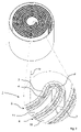
- FIG. 1 is a perspective view of a wick with wick sections lying on one another;
- FIG. 2 is a detail in the area of the central axis according to FIG. 1 ;
- FIG. 3 is a wick arrangement with ring channels.
- FIG. 1 schematically shows a perspective view of a wick 1 , which comprises carrier material 2 , which is bent over in a U-shaped pattern at a central axis 12 and is provided with wick material 3 , 4 on both sides.
- a first wick section 5 and a second wick section 6 which are of equal size and are flatly in contact with one another, are formed by the folded-over wick 1 .
- the carrier material 2 consists of special steel, while the wick materials are thin, absorbent nonwovens which are connected to the carrier material 2 .
- the wick 1 is accommodated in a cylindrical housing 9 , which is partially filled with a liquid anesthetic, which is not shown in FIG. 1 and is to be evaporated.
- a first flow channel 10 is formed by the consecutive outer sides of the wick sections 5 , 6 with the wick material 3 .
- the inner sides of the wick sections 5 , 6 with the wick material 4 form a second flow channel 11 .
- a first gas channel 13 opens into the first flow channel 10 in the area of the central axis 12 of the wick 1 , and a second gas channel 14 establishes the flow connection to the second flow channel 11 .
- the gas channels 13 , 14 are provided with openings, not shown specifically in FIG.
- the gas flow is illustrated by arrows 8 in FIG. 1 , and it extends from the second gas channel 14 into the second flow channel 11 and, after deflections at the inner wall of the housing 9 , back into the first flow channel 10 , and it flows out of the first flow channel 10 in the area of the central axis 12 into the first flow channel 13 .
- Spacers 7 which are arranged on both sides of the carrier material 2 , ensure that free flow is possible in both the first flow channel 10 and the second flow channel 11 .
- FIG. 2 shows an enlarged view of the wick 1 in the area of the central axis 12 .
- the wick sections 5 , 6 are formed by folding over the wick 1 .
- Identical components are designated by the same reference numbers as in FIG. 1 .
- FIG. 3 schematically shows a top view of a wick arrangement 20 , which comprises individual ring channels 21 , 22 , 23 , 24 .
- the walls of the ring channels 21 , 22 , 23 , 24 are formed by a gas-impermeable carrier material, which is coated on both sides with wick material 25 , which is not shown specifically in FIG. 3 .
- the ring channels 21 , 22 , 23 , 24 have partitions 26 , 27 , 28 , and perforations 29 , 30 , 31 , with which the gas flow entering the individual ring channels 21 , 22 , 23 , 24 through a flow channel 32 is deflected and leaves a flow channel 33 in the middle.
- the course of the flow is indicated by arrows 34 .
- the partitions 26 , 27 , 28 combined with the perforations 29 , 30 , 31 , are used to deflect the gas flow into an adjacent ring channel with reversal of the flow of the gas flow.
- the gas flows in counterflow in ring channels 21 , 22 located next to one another, as is indicated by the arrows 35 .
Abstract
Description
Claims (20)
Applications Claiming Priority (2)
| Application Number | Priority Date | Filing Date | Title |
|---|---|---|---|
| DE10134284.5-44 | 2001-07-13 | ||
| DE10134284A DE10134284C1 (en) | 2001-07-13 | 2001-07-13 | Wick for anesthetic vaporizer has gas impermeable core with coatings of wick material on both sides, wick being folded in half and double layer wound into spiral with closed end and central chamber |
Publications (2)
| Publication Number | Publication Date |
|---|---|
| US20030010476A1 US20030010476A1 (en) | 2003-01-16 |
| US7275539B2 true US7275539B2 (en) | 2007-10-02 |
Family
ID=7691794
Family Applications (1)
| Application Number | Title | Priority Date | Filing Date |
|---|---|---|---|
| US10/131,716 Expired - Fee Related US7275539B2 (en) | 2001-07-13 | 2002-04-24 | Wick arrangement for an anesthetic evaporator |
Country Status (3)
| Country | Link |
|---|---|
| US (1) | US7275539B2 (en) |
| DE (1) | DE10134284C1 (en) |
| GB (1) | GB2380681B (en) |
Cited By (3)
| Publication number | Priority date | Publication date | Assignee | Title |
|---|---|---|---|---|
| US20060231090A1 (en) * | 2005-04-13 | 2006-10-19 | Russell King | Inhalation apparatus |
| US20100051028A1 (en) * | 2008-08-29 | 2010-03-04 | Drãger Medical Ag & Co. Kg | Wick for an anesthetic evaporator |
| US20150064635A1 (en) * | 2013-09-05 | 2015-03-05 | Pro-Iroda Industries, Inc. | Wick of Flame Device |
Families Citing this family (7)
| Publication number | Priority date | Publication date | Assignee | Title |
|---|---|---|---|---|
| GB2471453B (en) * | 2009-06-29 | 2014-08-27 | Nigel Harold Morris | Fragrance capsule |
| US20120037344A1 (en) * | 2010-08-11 | 2012-02-16 | Celsia Technologies Taiwan, I | Flat heat pipe having swirl core |
| CN104874072B (en) * | 2014-02-28 | 2018-07-06 | 北京谊安医疗系统股份有限公司 | For the evaporator of Anesthesia machine and with its Anesthesia machine |
| JP6206389B2 (en) * | 2014-04-08 | 2017-10-04 | トヨタ自動車株式会社 | heat pipe |
| DE102014017675A1 (en) * | 2014-11-28 | 2016-06-02 | Drägerwerk AG & Co. KGaA | Anesthetic vaporizer and wick for an anesthetic vaporiser |
| CN106853269A (en) * | 2015-12-08 | 2017-06-16 | 北京谊安医疗系统股份有限公司 | A kind of pressure compensator |
| MX2021009073A (en) * | 2019-01-31 | 2021-09-10 | Dynavap Llc | Indirect exothermal vaporization matrix. |
Citations (3)
| Publication number | Priority date | Publication date | Assignee | Title |
|---|---|---|---|---|
| US3954920A (en) * | 1973-09-04 | 1976-05-04 | Parkland International Inc. | Gas humidification system |
| EP0220258A1 (en) | 1985-04-29 | 1987-05-06 | Penlon Ltd | Vaporizers and wick assemblies therefor. |
| US6325063B1 (en) * | 1998-01-26 | 2001-12-04 | George A. Volgyesi | Breath-powered mist inhaler |
Family Cites Families (10)
| Publication number | Priority date | Publication date | Assignee | Title |
|---|---|---|---|---|
| GB1088080A (en) * | 1966-07-01 | 1967-10-18 | Hutchinson Blease Ltd | Improvements in anaesthetic or analgesic vaporisers |
| US4034753A (en) * | 1975-09-29 | 1977-07-12 | Connel Allan A | Gas anesthesia machine |
| US6745822B1 (en) * | 1998-05-22 | 2004-06-08 | Matthew P. Mitchell | Concentric foil structure for regenerators |
| US6282371B1 (en) * | 1998-07-02 | 2001-08-28 | Richard J. Martin | Devices for reducing emissions, and methods for same |
| JP3090915B1 (en) * | 1999-04-16 | 2000-09-25 | 株式会社カンキョー | Heat exchanger, method of manufacturing the same, and dehumidifier including the same |
| CN1276233C (en) * | 2000-08-10 | 2006-09-20 | 株式会社康友 | Heat exchanger, method of manufacturing same and dehumidification machine including same |
| US6892795B1 (en) * | 2000-10-04 | 2005-05-17 | Airxchange, Inc. | Embossed regenerator matrix for heat exchanger |
| US7156155B2 (en) * | 2001-09-25 | 2007-01-02 | Honda Motor Co., Ltd. | Heat storage unit and manufacturing method therefor |
| JP3889698B2 (en) * | 2002-11-22 | 2007-03-07 | 本田技研工業株式会社 | Heat storage device |
| JP4205450B2 (en) * | 2003-02-19 | 2009-01-07 | 本田技研工業株式会社 | Thermal storage device element and method of manufacturing thermal storage device |
-
2001
- 2001-07-13 DE DE10134284A patent/DE10134284C1/en not_active Expired - Fee Related
-
2002
- 2002-04-24 US US10/131,716 patent/US7275539B2/en not_active Expired - Fee Related
- 2002-07-12 GB GB0216299A patent/GB2380681B/en not_active Expired - Fee Related
Patent Citations (5)
| Publication number | Priority date | Publication date | Assignee | Title |
|---|---|---|---|---|
| US3954920A (en) * | 1973-09-04 | 1976-05-04 | Parkland International Inc. | Gas humidification system |
| EP0220258A1 (en) | 1985-04-29 | 1987-05-06 | Penlon Ltd | Vaporizers and wick assemblies therefor. |
| US4774032A (en) * | 1985-04-29 | 1988-09-27 | Penlon Limted | Vaporizers and wick assemblies therefor |
| EP0220258B1 (en) * | 1985-04-29 | 1990-08-01 | Penlon Limited | Vaporizers and wick assemblies therefor |
| US6325063B1 (en) * | 1998-01-26 | 2001-12-04 | George A. Volgyesi | Breath-powered mist inhaler |
Cited By (7)
| Publication number | Priority date | Publication date | Assignee | Title |
|---|---|---|---|---|
| US20060231090A1 (en) * | 2005-04-13 | 2006-10-19 | Russell King | Inhalation apparatus |
| US7493898B2 (en) * | 2005-04-13 | 2009-02-24 | Healthline Medical, Inc. | Inhalation apparatus |
| US20100051028A1 (en) * | 2008-08-29 | 2010-03-04 | Drãger Medical Ag & Co. Kg | Wick for an anesthetic evaporator |
| US8496003B2 (en) * | 2008-08-29 | 2013-07-30 | Dräger Medical GmbH | Wick for an anesthetic evaporator |
| US20150064635A1 (en) * | 2013-09-05 | 2015-03-05 | Pro-Iroda Industries, Inc. | Wick of Flame Device |
| US10337730B2 (en) * | 2013-09-05 | 2019-07-02 | Pro-Iroda Industries, Inc. | Wick of flame device |
| US10458648B2 (en) | 2013-09-05 | 2019-10-29 | Pro-Iroda Industries, Inc. | Wick of flame device |
Also Published As
| Publication number | Publication date |
|---|---|
| US20030010476A1 (en) | 2003-01-16 |
| GB2380681B (en) | 2003-09-10 |
| DE10134284C1 (en) | 2002-11-21 |
| GB0216299D0 (en) | 2002-08-21 |
| GB2380681A (en) | 2003-04-16 |
Similar Documents
| Publication | Publication Date | Title |
|---|---|---|
| US7275539B2 (en) | Wick arrangement for an anesthetic evaporator | |
| FI69238C (en) | FOERBAETTRAT CIGARRETTFILTER | |
| AU595146B2 (en) | Capillary dialyzer | |
| FI73356B (en) | CIGARRETTFILTER. | |
| CA2611997C (en) | Hollow fiber arrangement | |
| JPH05336943A (en) | Ventilating type filter cigarette | |
| HU187477B (en) | Filter tip | |
| KR927003188A (en) | Spiral wound membrane separator with transfer and penetration / wash fluid flow control | |
| US4406294A (en) | Cigarette filter | |
| US4075297A (en) | Anesthetic vaporizer | |
| US8496003B2 (en) | Wick for an anesthetic evaporator | |
| US4679573A (en) | Adaptor assembly for airway tube | |
| FI77140B (en) | CIGARETTE FUERBAETTRAT. | |
| JPS6317468B2 (en) | ||
| RO87348B (en) | Cigarette filter | |
| US4237013A (en) | Hollow fiber permeability apparatus | |
| JPS60137273A (en) | Filter cigarette | |
| US3836129A (en) | Evaporator for liquid anesthetics | |
| IT8319617A1 (en) | FILTER FOR CIGARETTES | |
| GB2386842A (en) | Wick arrangement for an anaesthetic vaporizer | |
| NO844719L (en) | CIGARETTE NOZZLE | |
| JP2021502887A (en) | Membrane bundle placement with spacers | |
| US4747418A (en) | Cigarette filter unit | |
| IE60900B1 (en) | Cigarette filter | |
| US4643206A (en) | Cigarette filter |
Legal Events
| Date | Code | Title | Description |
|---|---|---|---|
| STCF | Information on status: patent grant |
Free format text: PATENTED CASE |
|
| AS | Assignment |
Owner name: DRAGER MEDICAL AG & CO. KG, GERMANY Free format text: CHANGE OF NAME;ASSIGNOR:DRAGER MEDICAL AG & CO. KGAA;REEL/FRAME:023196/0670 Effective date: 20051031 |
|
| AS | Assignment |
Owner name: DRAEGER MEDICAL GMBH, GERMANY Free format text: CHANGE OF NAME;ASSIGNOR:DRAEGER MEDICAL AG & CO. KG;REEL/FRAME:025137/0552 Effective date: 20100831 |
|
| FPAY | Fee payment |
Year of fee payment: 4 |
|
| FPAY | Fee payment |
Year of fee payment: 8 |
|
| AS | Assignment |
Owner name: DRAEGERWERK AG & CO. KGAA, GERMANY Free format text: MERGER;ASSIGNORS:DRAEGER MEDICAL GMBH;DRAEGERWERK AG & CO. KGAA;REEL/FRAME:036586/0718 Effective date: 20150603 |
|
| FEPP | Fee payment procedure |
Free format text: MAINTENANCE FEE REMINDER MAILED (ORIGINAL EVENT CODE: REM.); ENTITY STATUS OF PATENT OWNER: LARGE ENTITY |
|
| LAPS | Lapse for failure to pay maintenance fees |
Free format text: PATENT EXPIRED FOR FAILURE TO PAY MAINTENANCE FEES (ORIGINAL EVENT CODE: EXP.); ENTITY STATUS OF PATENT OWNER: LARGE ENTITY |
|
| STCH | Information on status: patent discontinuation |
Free format text: PATENT EXPIRED DUE TO NONPAYMENT OF MAINTENANCE FEES UNDER 37 CFR 1.362 |
|
| FP | Lapsed due to failure to pay maintenance fee |
Effective date: 20191002 |