US7274801B2 - Automatic target recognition system with Elliptical Laplacian Pyramid filter - Google Patents
Automatic target recognition system with Elliptical Laplacian Pyramid filter Download PDFInfo
- Publication number
- US7274801B2 US7274801B2 US10/355,124 US35512403A US7274801B2 US 7274801 B2 US7274801 B2 US 7274801B2 US 35512403 A US35512403 A US 35512403A US 7274801 B2 US7274801 B2 US 7274801B2
- Authority
- US
- United States
- Prior art keywords
- image
- elliptical
- sampled
- target
- laplacian operator
- Prior art date
- Legal status (The legal status is an assumption and is not a legal conclusion. Google has not performed a legal analysis and makes no representation as to the accuracy of the status listed.)
- Expired - Fee Related, expires
Links
Images


Classifications
-
- G—PHYSICS
- G06—COMPUTING; CALCULATING OR COUNTING
- G06V—IMAGE OR VIDEO RECOGNITION OR UNDERSTANDING
- G06V10/00—Arrangements for image or video recognition or understanding
- G06V10/20—Image preprocessing
- G06V10/255—Detecting or recognising potential candidate objects based on visual cues, e.g. shapes
Definitions
- the present invention relates to target recognition. More particularly, the present invention relates to automatic target recognition systems which employ a filter to pre-screen image data and nominate candidate targets.
- Weapon system performance and in particular, military weapon system performance is generally measured in terms of system accuracy.
- accuracy may depend on the system's ability to deliver a weapon on target.
- accuracy typically depends on the ability to periodically or continuously establish the correct position of a target. To improve accuracy, these systems often employ automatic target recognition systems and/or techniques.
- Automatic target recognition generally involves processing large quantities of image data (e.g., thermal image data) in order to identify and locate candidate targets.
- Automatic target recognition system performance is generally measured in terms of probability of detection (P d ) and probability of false detection (P fd ), where P d represents the likelihood that the system correctly detected and classified a target as a true target, and where P fd represents the likelihood that the system incorrectly classified a non-target as a true target.
- Curve A in FIG. 1 illustrates the relationship between P d and P fd for a typical automatic target recognition system.
- it is more desirable to have a system which maximizes P d while minimizing P fd as indicated by the dotted line to the left of curve A, as compared to the dashed line to the right of curve A.
- Pipeline processing is a well-known term which refers to a data processing technique that involves multiple, concurrently operating processing stages, where each stage performs a separate processing function.
- FIG. 2 illustrates an exemplary pipeline processing sequence 200 which might be employed in a conventional target recognition system.
- the exemplary pipeline processing sequence includes a pre-screen filter 205 , a target delineator 210 , a feature extractor 215 and a target classifier 220 .
- the pre-screen filter 205 processes the image data and, based on this processing, identifies candidate targets.
- the pre-screen filter 205 also provides a location of each candidate target identified within the image, e.g., by providing an x-y coordinate of a pixel that corresponds with the spatial center of each candidate target.
- the target delineator 210 uses the image data and the location information to determine the extent or boundary of any candidate target.
- the target delineator 210 may determine which pixels in proximity to the spatial center of a given candidate target also reflect or correspond to a portion of the candidate target.
- the feature extractor 215 measures certain predefined target features, such as length, width, perimeter and texture.
- the feature extractor 215 uses the measurements to generate a vector for the candidate target.
- the vector is then passed to the target classifier 220 .
- the target classifier 220 which has been previously trained using measurements of features from known true targets and known false targets, classifies the candidate target as a true target or a non-true target based on the vector it received from the feature extractor 215 .
- the pre-screen filter stage 205 illustrated in FIG. 2 is of particular importance. As stated, it identifies and locates candidate targets. As such, it establishes the processing load for the remaining stages. If the filter nominates a large number of candidate targets, the processing load is relatively large. If the filter nominates a small number of candidate targets, the processing load is relatively small. Therefore, it is important to employ a filter that effectively nominates targets, that is, with a relatively high P d and a relatively low P fd . Else, a significant amount of time is wasted processing data associated with false targets. It is also important to employ a filter that efficiently processes image data so that candidate targets are nominated in a timely manner.
- the present invention is directed to an automatic target recognition system and/or method, where the pre-screen filter stage of the pipeline processing sequence is implemented using an Elliptical Laplacian Pyramid (ELP) based algorithm.
- a Laplacian is a mathematical function which may be generated using a technique known as the Difference of Gaussians, as explained in greater detail below. As such, a Laplacian is sometimes referred to as a Difference of Gaussians (DOG). If the Gaussians are circular, so to is the resulting Laplacian.
- An elliptical Laplacian may be generated by a difference of two elliptical Gaussians. Thus, an elliptical Laplacian may be referred to as the Elliptical Difference of Gaussians (EDOG).
- EDOG Elliptical Difference of Gaussians
- the ELP based algorithm is a resolution sequence matched filter that capitalizes on the spatial nature of targets, which tend to exhibit a rectangular and/or elliptical shape at most aspect angles. Consequently, the algorithm efficiently and effectively identifies and locates candidate targets. This, in turn, helps to insure a relatively high P d :P fd ratio.
- an object of the present invention to provide an automatic target recognition system that is capable of efficiently and effectively identifying candidate targets based on image data.
- Another object of the present invention is to provide an automatic target recognition system that is capable of efficiently and effectively nominating candidate targets based on image data regardless of target range.
- Still another object of the present invention is to provide an automatic target recognition system that is capable of efficiently and effectively nominating candidate targets based on image data regardless of aspect angle.
- the aforementioned and other objectives are achieved by a method for identifying an object in an image.
- the method involves processing the image with an elliptical Laplacian operator and locating a peak value in the processed image. The object is then identified as a function of the peak value.
- the aforementioned and other objectives are achieved by a method for locating a target in an image.
- the method involves processing pixel data associated with the image through the use of an elliptical Laplacian operator.
- a vector is then generated, where the vector comprises a set of resultant values based on the previous step of processing the pixel data.
- a peak value is identified, and therefrom, the target is located as a function of a pixel location corresponding with the identified peak value.
- the aforementioned and other objectives are achieved through a target recognition system.
- the system includes means for receiving data associated with an image.
- the system also includes an elliptical Laplacian based pre-screen filter, which processes the image data and identifies therein a candidate target.
- FIG. 1 is a graph which illustrates the relationship between P d and P fd in a typical automatic target recognition system
- FIG. 2 is a block diagram which illustrates the processing stages associated with an exemplary pipeline processing sequence employed in a typical target recognition system
- FIG. 3 is a block diagram which illustrates the processing stages associated with a pipeline processing sequence that may be employed in a target recognition system according to exemplary embodiments of the present invention
- FIG. 4 is a block diagram which illustrates the processing functions associated with the ELP based pre-screen filter algorithm according to exemplary embodiments of the present invention
- FIG. 5 is a block diagram which illustrates, in greater detail, the processing functions associated with the ELP based pre-screen filter algorithm, according to exemplary embodiments of the present invention
- FIGS. 6A-6C are graphs which together illustrate an exemplary three-dimensional elliptical Laplacian operator
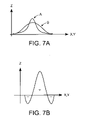
- FIGS. 7A-7C are graphs which together illustrate an exemplary three-dimensional circular Laplacian and the generation thereof using two three-dimensional circular Gaussians;
- FIG. 8 is a block diagram which illustrates the processing functions associated with an alternative ELP based pre-screen filter algorithm, according to exemplary embodiments of the present invention.
- FIGS. 9A-9C are graphs which illustrate the process of progressively enlarging the elliptical Laplacian operator used in processing an image in accordance with the alternative ELP based pre-screen filter algorithm of FIG. 8 .
- the present invention is described herein below with references to military type weapon systems. However, it will be understood that the present invention may apply to any system, military or otherwise, that requires efficient and effective recognition of targets, or more generally, objects embedded in image data.
- FIG. 3 depicts a pipeline processing sequence 300 .
- the pipeline processing sequence 300 includes a pre-screen filter 305 , a target delineator 310 , a feature extractor 315 and a target classifier 320 .
- the pre-screen filter 305 is, according to exemplary embodiments of the present invention, implemented using an ELP based algorithm.
- the ELP based algorithm employs elliptical Laplacian operators which closely reflect the spatial characteristics of prospective targets, such as trucks, tanks, missile sites and the like, to identify and locate these targets in the image data.
- FIG. 4 is a block diagram which illustrates the processing functions that are associated with the ELP based pre-screen filter algorithm 305 .
- the processing functions include an elliptical Laplacian kernel (ELK) 405 , a peak detector 410 and a peak pixel location recording function 415 .
- ELK elliptical Laplacian kernel
- each of these functions are implemented in software and/or firmware using well-known development techniques. However, as one skilled in the art will readily appreciate, some or all of these functions may be implemented in hardware.
- the ELK 405 receives image data from an imaging sensor (e.g., thermal image data from a forward-looking infrared sensor).
- image data involves a matrix of picture elements known as pixels, where each pixel represents a value (e.g., image intensity value) at a corresponding position (e.g., an x-y coordinate position) in the image.
- the ELK 405 then down-samples the image one or more times, as explained in greater detail below.
- the ELK 405 also generates an appropriate elliptical Laplacian operator, which it then uses to process (i.e., filter) the original and one or more down-sampled images.
- This processing results in a vector (i.e., a set of values) for each of the original and one or more down-sampled images, where each value in a given vector reflects a level of correlation between the elliptical Laplacian operator and a corresponding pixel in a corresponding one of the original or down-sampled images, as well as a number of neighboring pixels surrounding the corresponding pixel.
- the peak detector 410 then processes each vector. This processing results in the identification of one or more peak values (assuming there are one or more candidate targets embedded in the image data) and the position (e.g., the x-y position) of each pixel associated with each of the one or more peak values. Assuming the peak value exceeds a predefined level, the location of the corresponding pixel is stored as the location of a corresponding candidate target by the peak pixel location recording function 415 .
- FIG. 5 illustrates, in greater detail, the ELP based pre-screen filter 305 and, more particularly, the processing tasks associated with the ELK 405 .
- the ELK 405 receives the image data.
- the image data is then down-sampled as shown by task 505 .
- the data associated with the original image and each down-sampled image are then stored in memory. Down-sampling may involve a low-pass filtering process, whereby high frequency components are progressively removed from the image data. This may be achieved through decimation, whereby groups of adjacent pixels in the original image are averaged such that the resolution of the first down-sampled image is, for example, one-half that of the original image.
- the first down-sampled image may then be down-sampled in the same manner.
- the second down-sampled image would then have a resolution that is one-half that of the first down-sampled image.
- the down-sampling process continues until a pre-specified number of down-sampled images are obtained, where each subsequently generated down-sampled image has a progressively lower resolution than the image from which it was generated. If one were to picture the original image and all of the down-sampled images stacked in order, one on top of the other, with the highest resolution image on the bottom and the lowest resolution image on the top, one may think of the image stack in terms of a pyramid.
- the ELK 405 after generating and storing the down-sampled images, processes (i.e., filters) the original image data and the data associated with each down-sampled image using an elliptical Laplacian operator (ELO), as shown by task 510 .
- the ELK 405 may select, based on target range information (i.e., the distance between a prospective target and the image sensor), a number of images from amongst the original image and each of the down-sampled images, such that the size of any candidate target as it appears in the image data closely approximates the estimated size of the target given the aforementioned target range information.
- target range information i.e., the distance between a prospective target and the image sensor
- the ELK 405 then processes (i.e., filters) only the data associated with the selected images using the elliptical Laplacian operator.
- Target range information may be obtained through a variety of sources depending upon the nature of the weapon system. For example, target range information may be available through navigation equipment integral to or in communication with the weapon system, radar information or advanced intelligence.
- target range information may be available through navigation equipment integral to or in communication with the weapon system, radar information or advanced intelligence.
- FIG. 6A illustrates an exemplary three-dimensional elliptical Laplacian operator.
- this elliptical Laplacian operator covers a 50 ⁇ 50 pixel area in the xy plane, where the values contained in each pixel represent the amplitude (i.e., the z direction values) of the operator.
- FIGS. 6B and 6C illustrate the amplitude of the operator in the xz and yz planes, along the major and minor axes of the elliptical operator, respectively.
- the elliptical Laplacian operator shown in FIG. 6A is exemplary, and it will be understood that the amplitude and distribution will approximate the size and overall spatial characteristics of the expected target(s), as well as the level of contrast between the target(s) and the background imagery.
- the ELK 405 generates the elliptical Laplacian operator using a Difference of Gaussians (DOG) technique.
- a Gaussian is mathematical function that has a normal distribution.
- FIG. 7A illustrates two exemplary Gaussian functions, where Gaussian A has a greater amplitude than Gaussian B, but a smaller standard deviation (i.e., data spread about the mean value).
- subtracting Gaussian B from Gaussian A results in a Laplacian, for example, the Laplacian illustrated in FIG. 7B .
- Gaussian A and B are three-dimensional circular Gaussians, the resulting three-dimensional Laplacian will be circular as shown, for example, in FIG. 7C .
- a Laplacian operator may be generated by subtracting one circular Gaussian from another, as explained above.
- the resulting circular Laplacian is then manipulated to achieve an elliptical Laplacian operator which closely matches the size, spatial characteristics and image intensity of prospective targets.
- the Laplacian operator is generated, not by subtracting one circular Gaussian from another, but instead subtracting one elliptical Gaussian from another elliptical Gaussian.
- the resulting Laplacian will be elliptical.
- Gaussian may be represented by the following equation:
- G ⁇ ( X ) 1 ( 2 ⁇ ⁇ ) n / 2 ⁇ ⁇ ⁇ ⁇ 1 / 2 ⁇ exp ⁇ [ - 1 / 2 ⁇ ( X - M ) T ⁇ ⁇ - 1 ⁇ ( X - M ) ]
- X is a vector comprising, for example, xy coordinate values that define the Gaussian distribution in three-dimensional space
- M is a vector reflecting the mean value of vector X
- T is the symbol for transpose matrix
- ⁇ represents the standard deviation of Gaussian G(X).
- standard deviation ⁇ may be represented by the following covariance matrix:
- ⁇ [ ⁇ 11 ⁇ 12 ⁇ 21 ⁇ 22 ]
- ⁇ 11 represents the distribution of the corresponding Gaussian along the x axis
- ⁇ 22 represents the distribution of the Gaussian along the y axis
- ⁇ 12 and ⁇ 21 represent the distribution of the Gaussian where the Gaussian has been rotated about the x and y axes respectively.
- the terms ⁇ 11 and ⁇ 22 are referred to as the auto-correlation terms, and if they are of equal value, the corresponding Gaussian is circular. If ⁇ 11 and ⁇ 22 are not of equal value, the corresponding Gaussian is elliptical. Thus, in order to generate an appropriate elliptical Laplacian operator, the values of ⁇ 11 and ⁇ 22 must be set accordingly.
- ⁇ 12 the ⁇ 21 are referred to as the cross-correlation terms.
- ⁇ 12 and ⁇ 21 must also be set to appropriate values. If ⁇ 12 and ⁇ 21 are both equal to zero, the corresponding Gaussian will be symmetric about the x and y axes.
- the values for ⁇ 12 and ⁇ 21 should be selected so that the major axis of the resulting elliptical Laplacian operator is parallel to the horizon, where the major axis of the prospective candidate target(s) are parallel to the horizon, or more specifically, parallel to the major axis of the prospective targets themselves, where the major axis of the prospective candidate target(s) are parallel to neither the horizon or the image sensor.
- the DOG is but one approach that may be employed for generating an elliptical Laplacian operator.
- functions other than Gaussians may be used in a similar manner to generate an elliptical Laplacian operator, such as quadratic functions or sine waves.
- the ELK 405 uses the operator to process (i.e., filter) each of the original and down-sampled images or, alternatively, a select number of these images based on target range.
- processing each image involves a convolution process. This may be achieved by overlaying the elliptical Laplacian operator atop a given pixel in a given image. For those images having higher resolutions, the size of the elliptical Laplacian operator will in all likelihood be larger than a single pixel. Thus, the elliptical Laplacian operator will overlay not only the given pixel but a number of neighboring pixels as well.
- the value of the given pixel would be multiplied by the corresponding elliptical Laplacian operator value. Additionally, the value of each neighboring pixel covered by the operator are likewise multiplied by a corresponding value associated with the elliptical Laplacian operator. The multiplication values are then summed and averaged. The average value is then attributed to the given pixel. In general, this process is repeated for each pixel in each image (i.e., the original image and the down-sampled images) or, alternatively, each pixel in each of the images selected from amongst the original and down-sampled images based on target range.
- pixels located on the edge of an image or within a certain distance from the edge of an image, depending on the size of the elliptical Laplacian operator, may be excluded from the convolution process.
- the resulting vector i.e., set of values for each processed image is passed on to the peak detector 410 , as shown in FIGS. 4 and 5 .
- the peak detector 410 scans the values and identifies a peak value.
- the peak value is compared to a threshold, where the threshold level may be a function of the image background, and more specifically, a predefined number of standard deviations above the mean image background value. If the peak value is greater than the threshold value, the peak value is attributed to a candidate target. If the peak value is not greater than the threshold value, it is assumed there is no distinguishable candidate target in that particular image.
- the position (e.g., the x-y position) of the pixel that corresponds with the peak value is stored by the record peak pixel location function 415 . It should be noted that more than one peak value may be identified in a given image (i.e., in a given vector), particularly where more than one candidate target is embedded in the image data.
- the image data and candidate target location information are passed to the Target delineator 310 , which, as stated, establishes the extent of each candidate target.
- the feature extractor 315 measures the various features associated with each candidate target and, based thereon, the target classifier 320 classifies each candidate target as a true target or a non-true target.
- FIG. 8 illustrates the processing tasks associated with an alternative ELP based pre-screen filter algorithm.
- the ELK 405 receives the image data.
- the image data is down-sampled.
- the ELO is used to process (i.e., filter) the input image and/or one or more down-sampled images.
- the input image may not be down-sampled.
- the ELO may be enlarged.
- the ELO is progressively enlarged by a 2:1 ratio. It will be readily apparent, however, that the ELO may be enlarged using a ratio other than a 2:1 ratio. It will also be readily apparent that by processing (i.e., filtering) the input image with progressively larger ELOs, the P d associated with relatively large targets appearing in the input image increases.
- FIGS. 9A-C illustrate the concept of progressively enlarging the ELO, per task 810 . If, for example, FIG. 9A reflects the ELO, FIG. 9B reflects the larger 2 ⁇ ELO. Likewise, FIG. 9C reflects the even larger 4 ⁇ ELO.
Abstract
Description
where X is a vector comprising, for example, xy coordinate values that define the Gaussian distribution in three-dimensional space; where M is a vector reflecting the mean value of vector X; where T is the symbol for transpose matrix; and where Σ represents the standard deviation of Gaussian G(X). Further, standard deviation Σ may be represented by the following covariance matrix:
where σ11 represents the distribution of the corresponding Gaussian along the x axis, σ22 represents the distribution of the Gaussian along the y axis, and σ12 and σ21 represent the distribution of the Gaussian where the Gaussian has been rotated about the x and y axes respectively. The terms σ11 and σ22 are referred to as the auto-correlation terms, and if they are of equal value, the corresponding Gaussian is circular. If σ11 and σ22 are not of equal value, the corresponding Gaussian is elliptical. Thus, in order to generate an appropriate elliptical Laplacian operator, the values of σ11 and σ22 must be set accordingly.
Claims (18)
Priority Applications (1)
| Application Number | Priority Date | Filing Date | Title |
|---|---|---|---|
| US10/355,124 US7274801B2 (en) | 2003-01-31 | 2003-01-31 | Automatic target recognition system with Elliptical Laplacian Pyramid filter |
Applications Claiming Priority (1)
| Application Number | Priority Date | Filing Date | Title |
|---|---|---|---|
| US10/355,124 US7274801B2 (en) | 2003-01-31 | 2003-01-31 | Automatic target recognition system with Elliptical Laplacian Pyramid filter |
Publications (2)
| Publication Number | Publication Date |
|---|---|
| US20040151343A1 US20040151343A1 (en) | 2004-08-05 |
| US7274801B2 true US7274801B2 (en) | 2007-09-25 |
Family
ID=32770468
Family Applications (1)
| Application Number | Title | Priority Date | Filing Date |
|---|---|---|---|
| US10/355,124 Expired - Fee Related US7274801B2 (en) | 2003-01-31 | 2003-01-31 | Automatic target recognition system with Elliptical Laplacian Pyramid filter |
Country Status (1)
| Country | Link |
|---|---|
| US (1) | US7274801B2 (en) |
Cited By (6)
| Publication number | Priority date | Publication date | Assignee | Title |
|---|---|---|---|---|
| US20070211930A1 (en) * | 2006-03-09 | 2007-09-13 | Terry Dolwick | Attribute based image enhancement and display for medical imaging applications |
| US8150101B2 (en) | 2006-11-13 | 2012-04-03 | Cybernet Systems Corporation | Orientation invariant object identification using model-based image processing |
| US8264400B2 (en) | 2010-06-03 | 2012-09-11 | Raytheon Company | Signature matching method and apparatus |
| US20130293882A1 (en) * | 2011-06-21 | 2013-11-07 | Alakai Defense Systems, Inc. | Laser detection system and method |
| US20160307037A1 (en) * | 2008-06-18 | 2016-10-20 | Gracenote, Inc. | Digital Video Content Fingerprinting Based on Scale Invariant Interest Region Detection with an Array of Anisotropic Filters |
| US10423654B2 (en) | 2009-06-10 | 2019-09-24 | Gracenote, Inc. | Media fingerprinting and identification system |
Families Citing this family (3)
| Publication number | Priority date | Publication date | Assignee | Title |
|---|---|---|---|---|
| WO2013102797A1 (en) | 2012-01-06 | 2013-07-11 | Aselsan Elektronik Sanayi Ve Ticaret Anonim Sirketi | System and method for detecting targets in maritime surveillance applications |
| CN104237493B (en) * | 2014-07-11 | 2016-01-06 | 天津中医药大学 | Pyramid screening technique carries out the method for classification and identification to endogenous metabolites |
| WO2023017398A1 (en) * | 2021-08-08 | 2023-02-16 | Vayyar Imaging Ltd. | Systems and methods for scanning concealed objects |
Citations (2)
| Publication number | Priority date | Publication date | Assignee | Title |
|---|---|---|---|---|
| US6516087B1 (en) * | 2000-01-10 | 2003-02-04 | Sensar, Inc. | Method for real time correlation of stereo images |
| US6801645B1 (en) * | 1999-06-23 | 2004-10-05 | Icad, Inc. | Computer aided detection of masses and clustered microcalcifications with single and multiple input image context classification strategies |
-
2003
- 2003-01-31 US US10/355,124 patent/US7274801B2/en not_active Expired - Fee Related
Patent Citations (2)
| Publication number | Priority date | Publication date | Assignee | Title |
|---|---|---|---|---|
| US6801645B1 (en) * | 1999-06-23 | 2004-10-05 | Icad, Inc. | Computer aided detection of masses and clustered microcalcifications with single and multiple input image context classification strategies |
| US6516087B1 (en) * | 2000-01-10 | 2003-02-04 | Sensar, Inc. | Method for real time correlation of stereo images |
Non-Patent Citations (3)
| Title |
|---|
| Burt, Peter J., Adelson, Edward H.; "The Laplacian Pyramid as a Compact Image Code"; IEEE Transactions on Communciations, vol. COM-31, No. 4, Apr. 1983. * |
| Jackson, Scott A., Ahuja, Narendra; "Elliptical Gaussian Filters"; IEEE; 1996. * |
| Serafim, Antonio F. Limas; "Object Detection in Images of Natural Scenes Represented by AR Models Using Laplacian Pyramids: Application to Leather Defects Localization"; IEEE; 1992. * |
Cited By (18)
| Publication number | Priority date | Publication date | Assignee | Title |
|---|---|---|---|---|
| US20070211930A1 (en) * | 2006-03-09 | 2007-09-13 | Terry Dolwick | Attribute based image enhancement and display for medical imaging applications |
| US9483867B2 (en) | 2006-11-13 | 2016-11-01 | Cybernet Systems Corporation | Orientation invariant object identification using model-based image processing |
| US10861219B2 (en) | 2006-11-13 | 2020-12-08 | Cybernet Systems Corp. | Orientation invariant object identification using model-based image processing |
| US8687849B2 (en) | 2006-11-13 | 2014-04-01 | Cybernet Systems Corporation | Orientation invariant object identification using model-based image processing |
| US8150101B2 (en) | 2006-11-13 | 2012-04-03 | Cybernet Systems Corporation | Orientation invariant object identification using model-based image processing |
| US9082219B2 (en) | 2006-11-13 | 2015-07-14 | Cybernet Systems Corporation | Orientation invariant object identification using model-based image processing |
| US9652672B2 (en) * | 2008-06-18 | 2017-05-16 | Gracenote, Inc. | Digital video content fingerprinting based on scale invariant interest region detection with an array of anisotropic filters |
| US20160307037A1 (en) * | 2008-06-18 | 2016-10-20 | Gracenote, Inc. | Digital Video Content Fingerprinting Based on Scale Invariant Interest Region Detection with an Array of Anisotropic Filters |
| US11126650B2 (en) | 2009-06-10 | 2021-09-21 | Roku, Inc. | Media fingerprinting and identification system |
| US10423654B2 (en) | 2009-06-10 | 2019-09-24 | Gracenote, Inc. | Media fingerprinting and identification system |
| US11036783B2 (en) | 2009-06-10 | 2021-06-15 | Roku, Inc. | Media fingerprinting and identification system |
| US11042585B2 (en) | 2009-06-10 | 2021-06-22 | Roku, Inc. | Media fingerprinting and identification system |
| US11334615B2 (en) | 2009-06-10 | 2022-05-17 | Roku, Inc. | Media fingerprinting and identification system |
| US11455328B2 (en) | 2009-06-10 | 2022-09-27 | Roku, Inc. | Media fingerprinting and identification system |
| US11630858B2 (en) | 2009-06-10 | 2023-04-18 | Roku, Inc. | Media fingerprinting and identification system |
| US8264400B2 (en) | 2010-06-03 | 2012-09-11 | Raytheon Company | Signature matching method and apparatus |
| US20130293882A1 (en) * | 2011-06-21 | 2013-11-07 | Alakai Defense Systems, Inc. | Laser detection system and method |
| US9157801B2 (en) * | 2011-06-21 | 2015-10-13 | Alakai Defense Systems, Inc. | Laser detection system having an output beam directed through a telescope |
Also Published As
| Publication number | Publication date |
|---|---|
| US20040151343A1 (en) | 2004-08-05 |
Similar Documents
| Publication | Publication Date | Title |
|---|---|---|
| EP2138978B1 (en) | System and method for finding stable keypoints in a picture image using localized scale space properties | |
| US8081798B2 (en) | Method and system for detecting polygon boundaries of structures in images as particle tracks through fields of corners and pixel gradients | |
| US7430303B2 (en) | Target detection method and system | |
| Yilmaz et al. | Target tracking in airborne forward looking infrared imagery | |
| EP2064652B1 (en) | Method of image processing | |
| EP1329850B1 (en) | Apparatus, program and method for detecting both stationary objects and moving objects in an image | |
| Réfrégier et al. | Statistical image processing techniques for noisy images: an application-oriented approach | |
| US8538077B2 (en) | Detecting an interest point in an image using edges | |
| US8170279B2 (en) | Adaptive match metric selection for automatic target recognition | |
| US20080205764A1 (en) | Information processing apparatus, method, and program | |
| US7912321B1 (en) | Image registration with uncertainty analysis | |
| US6961481B2 (en) | Method and apparatus for image processing using sub-pixel differencing | |
| US7356185B2 (en) | Preparation of a digital image with subsequent edge detection | |
| WO2006086051A2 (en) | Method and apparatus for tracking a movable object | |
| US7274801B2 (en) | Automatic target recognition system with Elliptical Laplacian Pyramid filter | |
| US20220148200A1 (en) | Estimating the movement of an image position | |
| Sledge et al. | Target detection and segmentation in circular-scan synthetic aperture sonar images using semisupervised convolutional encoder–decoders | |
| US8594457B1 (en) | Correlation image detection | |
| EP3044734B1 (en) | Isotropic feature matching | |
| US5557543A (en) | Tracking apparatus | |
| US20180299228A1 (en) | Improvements in and relating to missile targeting | |
| Goudail et al. | Optimal and suboptimal detection of a target with random grey levels imbedded in non-overlapping noise | |
| US9177228B1 (en) | Method and system for fusion of fast surprise and motion-based saliency for finding objects of interest in dynamic scenes | |
| Bazin et al. | Particle filter approach adapted to catadioptric images for target tracking application | |
| Jurgensen | The rotated speeded-up robust features algorithm (R-SURF) |
Legal Events
| Date | Code | Title | Description |
|---|---|---|---|
| AS | Assignment |
Owner name: LOCKHEED MARTIN ELECTRONICS & MISSILES, FLORIDA Free format text: ASSIGNMENT OF ASSIGNORS INTEREST;ASSIGNOR:LEE, HARRY C.;REEL/FRAME:013717/0222 Effective date: 20030130 |
|
| AS | Assignment |
Owner name: LOCKHEED MARTIN CORPORATION, MARYLAND Free format text: ASSIGNMENT OF ASSIGNORS INTEREST;ASSIGNOR:LEE, HARRY C.;REEL/FRAME:019716/0482 Effective date: 20030130 |
|
| STCF | Information on status: patent grant |
Free format text: PATENTED CASE |
|
| FPAY | Fee payment |
Year of fee payment: 4 |
|
| FPAY | Fee payment |
Year of fee payment: 8 |
|
| FEPP | Fee payment procedure |
Free format text: MAINTENANCE FEE REMINDER MAILED (ORIGINAL EVENT CODE: REM.); ENTITY STATUS OF PATENT OWNER: LARGE ENTITY |
|
| LAPS | Lapse for failure to pay maintenance fees |
Free format text: PATENT EXPIRED FOR FAILURE TO PAY MAINTENANCE FEES (ORIGINAL EVENT CODE: EXP.); ENTITY STATUS OF PATENT OWNER: LARGE ENTITY |
|
| STCH | Information on status: patent discontinuation |
Free format text: PATENT EXPIRED DUE TO NONPAYMENT OF MAINTENANCE FEES UNDER 37 CFR 1.362 |
|
| FP | Lapsed due to failure to pay maintenance fee |
Effective date: 20190925 |