US726905A - Drying-rack. - Google Patents
Drying-rack. Download PDFInfo
- Publication number
- US726905A US726905A US11077702A US1902110777A US726905A US 726905 A US726905 A US 726905A US 11077702 A US11077702 A US 11077702A US 1902110777 A US1902110777 A US 1902110777A US 726905 A US726905 A US 726905A
- Authority
- US
- United States
- Prior art keywords
- drying
- standard
- rack
- head
- heads
- Prior art date
- Legal status (The legal status is an assumption and is not a legal conclusion. Google has not performed a legal analysis and makes no representation as to the accuracy of the status listed.)
- Expired - Lifetime
Links
Images

Classifications
-
- A—HUMAN NECESSITIES
- A47—FURNITURE; DOMESTIC ARTICLES OR APPLIANCES; COFFEE MILLS; SPICE MILLS; SUCTION CLEANERS IN GENERAL
- A47F—SPECIAL FURNITURE, FITTINGS, OR ACCESSORIES FOR SHOPS, STOREHOUSES, BARS, RESTAURANTS OR THE LIKE; PAYING COUNTERS
- A47F5/00—Show stands, hangers, or shelves characterised by their constructional features
- A47F5/08—Show stands, hangers, or shelves characterised by their constructional features secured to the wall, ceiling, or the like; Wall-bracket display devices
- A47F5/0892—Suspended show stands, e.g. secured to the ceiling by means of cords or chains
-
- A—HUMAN NECESSITIES
- A47—FURNITURE; DOMESTIC ARTICLES OR APPLIANCES; COFFEE MILLS; SPICE MILLS; SUCTION CLEANERS IN GENERAL
- A47B—TABLES; DESKS; OFFICE FURNITURE; CABINETS; DRAWERS; GENERAL DETAILS OF FURNITURE
- A47B46/00—Cabinets, racks or shelf units, having one or more surfaces adapted to be brought into position for use by extending or pivoting
- A47B46/005—Cabinets, racks or shelf units, having one or more surfaces adapted to be brought into position for use by extending or pivoting by displacement in a vertical plane; by rotating about a horizontal axis
Definitions
- My present invention has for its object to provide an improved drying-rack adapted to be suspended from the ceiling or other overhead support, and especially adapted for use in connection with a range or cooking-stove.
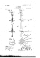
- Figure 1 is a view in side elevation, with some parts sectioned, showing a range or cooking-stove and one of my improved drying-racks suspended from the ceiling.
- Fig. 2 is a front elevation of the drying-rack with some parts removed and others broken away.
- Fig. 3 is a side elevation of the drying-rack with some parts broken away.
- Fig.4 is a plan view of the same with some parts removed, and
- Fig. 5 is a horizontal section on the line 00 m of Fig. 3.
- the numeral 1 indicates the ceiling and the numeral 2 the floor of a room.
- the numeral 3 indicates an ordinary range or cooking-stove and the numeral 4. a stoveipe.
- D My improved drying-rack is independently supported from the ceiling or similar-overhead support and is preferably dropped vertically over the stove close to. the stovepipe, where all articles placed thereon will be subject to the heat which rises from the stove and is radiated from the Stovepipe.
- the depending standard of the rack is afforded by a straight piece of angle-iron a, which at its upper end is rigidly secured to the ceiling 1 by a strong bracket I), screwed, bolted, or otherwise fastened to the said ceiling.
- the angle-iron standard a is detachably secured to said bracket 17 by a single nutted bolt 19.
- the bracketb is formed to fit the angular exterior of the standard a, and it is provided with depending lug b which engages the inner angle thereof and assists the bolt 1) in rigidly holding the said depending standard against lateral movements.
- ⁇ Vorking loosely on the angular standard C0 is one or more (preferably several) sliding heads j, which are segmental in form and are provided with angular hubsf, which fit theouter angle of the standard a and embrace the flanges thereof, as best shown in Fig. 5. 6
- the inturned or flanged vertical edges f 2 of the angular hubs f engage the edges of the standard a at points considerably above the horizontal planes of. the said heads f, and consequently cause the said hubs f to pinch or bite upon the standard a whenever weight is placed upon the said heads.
- the said heads are of segmental form and project from the hubs f in a direction opposite to the side on which the flanges f project. Hence whenever weight is placed on one of the segmental heads f its hub bites upon the standard and locks the said head against downwardsliding movement. On the other hand, when force is applied to one of the heads, tending to raise the same, it will freely slide upward.
- each headf is a plurality of radial supporting rods or arms g, the inner ends of which are hooked or 'bent,-as shown at g.
- These hooked ends g are adapted to be passed through perforations in the said heads f, as best shown in Figs. 3 and 5.
- the arms 9 are detachably and adjustably held in working positions.
- the weight of the arms g in themselves tends to cause the hubs f on the sliding heads f to frictionally clamp or bite upon the depending standard a and hold the head where set.
- the more weight that is placed upon the supporting-rods g the greater will be this biting action.
- the heads f are preferably provided-with one or more (as shown two) perforations f through which the crooked end of one of the removed radial arms g or similar device may be inserted from below to thereby readily raise or lower the heads f.
- perforations f through which the crooked end of one of the removed radial arms g or similar device may be inserted from below to thereby readily raise or lower the heads f.
- this drying-rack may be put will readily suggest themselves to all persons who may have occasion to use the same.
- Several of the common uses thereof may be enumerated as follows: the drying of clothes, holding of dishes to be warmed, drying of fruits, be.
- the depending standard a is provided at its lower end with a detachable hook 7:, to which a kettle 5 or similar cooking utensil may be suspended above the stove, as indicated in Fig. 1.
- a drying-rack comprising an angle-iron standard, and a segmental head provided with supporting-arms and having a hub portion which fits and slides freely upon the outer angular portion of said standard, and which hub has vertically-extended converging biting lugs or flanges which, under a downward pressure on said head, bite upon the edges ofthe diverging sides of said angular standard and frictionally hold the said head, substantially as described.
- a drying-rack comprising a standard and a head slidable thereon which head is in the form of a horizontal plate provided with perforations through its inner portion and a perforation near its outer edge and also has biting-jaws for action on said standard to frictionally hold said head to said standard, under downward pressure on the former, in combination with the rods or arms 9 having the crooked ends g detachably engaged in the inner perforation and adapted to be engaged with said outer perforations to raise the head, substantially as described.
Description
No. 726,905. PATENTBD MAY 5, 1903. I
I. L. GLEASON.
DRYING RACK. APPLIOATION FILED JUNE 9, 1902.
Fig 1.
' No. 726,905. PATENTED MAY 5, 1903. I. L. (:rLEASON.
DRYING RACK.
APPLICATION IILED JUNE 9. 190 2. no MODEL. 2 SHEETS-SHEET z.
ff I I] 223 WWI-Wigs" I PETERS COPHOTD-LITMH wwmpwn. 4
UNITED STATES Patented May 5, 1903.
IRA L. GLEASON, OF HUTCHINSON, MINNESOTA.
DRYING-RACK.
SPECIFICATION forming part of Letters Patent No. 726,905, dated May 5, 1903.
Application filed June 9, 1902. Serial No. 110,777. (No model.)
T0 at whom it may concern.-
Beit known that I, IRA L. GLEAsoN, a citizen of the United States, residing at Hutchinson, in the county of McLeod and State of Minnesota, have invented certain new and useful Improvements in Drying-Racks; and I do hereby declare the following to be afull, clear, and exact description of the invention, such as will enable others skilled in the art to which it appertains to make and use thesame.
My present invention has for its object to provide an improved drying-rack adapted to be suspended from the ceiling or other overhead support, and especially adapted for use in connection with a range or cooking-stove.
To the above ends the invention consists of the novel devices and combinations of devices hereinafter described, and defined in the claims.
The invention is illustrated in the accompanying drawings, wherein like characters indicate like parts throughout the several views.
Figure 1 is a view in side elevation, with some parts sectioned, showing a range or cooking-stove and one of my improved drying-racks suspended from the ceiling. Fig. 2 is a front elevation of the drying-rack with some parts removed and others broken away. Fig. 3 is a side elevation of the drying-rack with some parts broken away. Fig.4 is a plan view of the same with some parts removed, and Fig. 5 is a horizontal section on the line 00 m of Fig. 3.
The numeral 1 indicates the ceiling and the numeral 2 the floor of a room.
The numeral 3 indicates an ordinary range or cooking-stove and the numeral 4. a stoveipe. D My improved drying-rack is independently supported from the ceiling or similar-overhead support and is preferably dropped vertically over the stove close to. the stovepipe, where all articles placed thereon will be subject to the heat which rises from the stove and is radiated from the Stovepipe. The depending standard of the rack is afforded by a straight piece of angle-iron a, which at its upper end is rigidly secured to the ceiling 1 by a strong bracket I), screwed, bolted, or otherwise fastened to the said ceiling. The angle-iron standard a is detachably secured to said bracket 17 by a single nutted bolt 19. The bracketb is formed to fit the angular exterior of the standard a, and it is provided with depending lug b which engages the inner angle thereof and assists the bolt 1) in rigidly holding the said depending standard against lateral movements.
\Vorking loosely on the angular standard C0 is one or more (preferably several) sliding heads j, which are segmental in form and are provided with angular hubsf, which fit theouter angle of the standard a and embrace the flanges thereof, as best shown in Fig. 5. 6
The inturned or flanged vertical edges f 2 of the angular hubs f engage the edges of the standard a at points considerably above the horizontal planes of. the said heads f, and consequently cause the said hubs f to pinch or bite upon the standard a whenever weight is placed upon the said heads. The said heads are of segmental form and project from the hubs f in a direction opposite to the side on which the flanges f project. Hence whenever weight is placed on one of the segmental heads f its hub bites upon the standard and locks the said head against downwardsliding movement. On the other hand, when force is applied to one of the heads, tending to raise the same, it will freely slide upward. Applied to each headf is a plurality of radial supporting rods or arms g, the inner ends of which are hooked or 'bent,-as shown at g. These hooked ends g are adapted to be passed through perforations in the said heads f, as best shown in Figs. 3 and 5. In this way the arms 9 are detachably and adjustably held in working positions. As is evident, the weight of the arms g in themselves tends to cause the hubs f on the sliding heads f to frictionally clamp or bite upon the depending standard a and hold the head where set. As is further obvious, the more weight that is placed upon the supporting-rods g the greater will be this biting action.
The heads f are preferably provided-with one or more (as shown two) perforations f through which the crooked end of one of the removed radial arms g or similar device may be inserted from below to thereby readily raise or lower the heads f. As is evident, to raise one of the heads, together with its load, it would be only necessary to push upward on the head, while to lower the head it is necessary to rock the loaded side of the head slightly upward, pulling downward on the head. This latter action, as Well as the former, may be readily accomplished by means of a rod having its crooked end inserted upward through one of the perforations f To remove the heads f, they are drawn downward off from the lower end ofthe depending standard a, and they are of course applied to said standard by reverse movements.
The various uses to which this drying-rack may be put will readily suggest themselves to all persons who may have occasion to use the same. Several of the common uses thereof may be enumerated as follows: the drying of clothes, holding of dishes to be warmed, drying of fruits, be.
, Preferably the depending standard a is provided at its lower end with a detachable hook 7:, to which a kettle 5 or similar cooking utensil may be suspended above the stove, as indicated in Fig. 1.
' It will of course be understood that the device above described is capable of considerable modification within the scope of my invention as herein set forth and claimed What I claim, and desire to secure by Letters Patent of the United States, is as follows:
1. A drying-rack comprising an angle-iron standard, and a segmental head provided with supporting-arms and having a hub portion which fits and slides freely upon the outer angular portion of said standard, and which hub has vertically-extended converging biting lugs or flanges which, under a downward pressure on said head, bite upon the edges ofthe diverging sides of said angular standard and frictionally hold the said head, substantially as described.
2. A drying-rack comprising a standard and a head slidable thereon which head is in the form of a horizontal plate provided with perforations through its inner portion and a perforation near its outer edge and also has biting-jaws for action on said standard to frictionally hold said head to said standard, under downward pressure on the former, in combination with the rods or arms 9 having the crooked ends g detachably engaged in the inner perforation and adapted to be engaged with said outer perforations to raise the head, substantially as described.
In testimony whereof I aflix my signature in presence of two witnesses.
IRA L. GLEASON.
Witnesses:
JOHN DEAN, D. A. ADAMS.
Priority Applications (1)
| Application Number | Priority Date | Filing Date | Title |
|---|---|---|---|
| US11077702A US726905A (en) | 1902-06-09 | 1902-06-09 | Drying-rack. |
Applications Claiming Priority (1)
| Application Number | Priority Date | Filing Date | Title |
|---|---|---|---|
| US11077702A US726905A (en) | 1902-06-09 | 1902-06-09 | Drying-rack. |
Publications (1)
| Publication Number | Publication Date |
|---|---|
| US726905A true US726905A (en) | 1903-05-05 |
Family
ID=2795415
Family Applications (1)
| Application Number | Title | Priority Date | Filing Date |
|---|---|---|---|
| US11077702A Expired - Lifetime US726905A (en) | 1902-06-09 | 1902-06-09 | Drying-rack. |
Country Status (1)
| Country | Link |
|---|---|
| US (1) | US726905A (en) |
Cited By (3)
| Publication number | Priority date | Publication date | Assignee | Title |
|---|---|---|---|---|
| US2765136A (en) * | 1951-05-03 | 1956-10-02 | Knapp Mills Inc | Support means |
| US2774562A (en) * | 1952-12-08 | 1956-12-18 | Little Garden Corp | Supporting apparatus |
| US4447049A (en) * | 1982-08-02 | 1984-05-08 | Alumin-Art Plating Company | Apparatus for holding a work piece |
-
1902
- 1902-06-09 US US11077702A patent/US726905A/en not_active Expired - Lifetime
Cited By (3)
| Publication number | Priority date | Publication date | Assignee | Title |
|---|---|---|---|---|
| US2765136A (en) * | 1951-05-03 | 1956-10-02 | Knapp Mills Inc | Support means |
| US2774562A (en) * | 1952-12-08 | 1956-12-18 | Little Garden Corp | Supporting apparatus |
| US4447049A (en) * | 1982-08-02 | 1984-05-08 | Alumin-Art Plating Company | Apparatus for holding a work piece |
Similar Documents
| Publication | Publication Date | Title |
|---|---|---|
| US726905A (en) | Drying-rack. | |
| US586977A (en) | Garment-rack | |
| US701079A (en) | Adjustable shelf-bracket. | |
| US200767A (en) | Improvement in brackets | |
| US1135181A (en) | Adjustable washstand. | |
| US1223802A (en) | Picture-hanger. | |
| US402885A (en) | Display-rack | |
| US985062A (en) | Stovepipe-hanger. | |
| US316922A (en) | Pipe-hanger | |
| US598862A (en) | donica | |
| US373002A (en) | Frank aldeich | |
| US613185A (en) | Combined curtain-pole adjuster and support | |
| US746809A (en) | Device for lifting kettles from stoves, &c. | |
| US346694A (en) | wallace | |
| US186612A (en) | Improvement in clothes-driers | |
| US158686A (en) | Improvement in window-conservatories | |
| US440453A (en) | Combined pot-lifter and stove-shelf | |
| US606967A (en) | Stovepipe attachment | |
| US507394A (en) | William trewhella | |
| US804906A (en) | Clothes-rack. | |
| US317766A (en) | Kitchen-cabinet | |
| US630430A (en) | Clothes-rack. | |
| US150604A (en) | Improvement in tobacco-hangers | |
| US160359A (en) | Improvement in clothes-frames | |
| US744901A (en) | Clothes-drier. |