US7255935B2 - Organic electroluminescent element and luminescent apparatus employing the same - Google Patents
Organic electroluminescent element and luminescent apparatus employing the same Download PDFInfo
- Publication number
- US7255935B2 US7255935B2 US10/009,021 US902102A US7255935B2 US 7255935 B2 US7255935 B2 US 7255935B2 US 902102 A US902102 A US 902102A US 7255935 B2 US7255935 B2 US 7255935B2
- Authority
- US
- United States
- Prior art keywords
- layer
- electroluminescent element
- transfer layer
- organic
- organic electroluminescent
- Prior art date
- Legal status (The legal status is an assumption and is not a legal conclusion. Google has not performed a legal analysis and makes no representation as to the accuracy of the status listed.)
- Expired - Fee Related, expires
Links
- 0 [1*]C1=C(C)C([4*])=C([3*])C(C)=C1[2*].[1*]C1=C(C)C([4*])=C([3*])C([2*])=C1C.[1*]C1=C([2*])C([3*])=C([4*])C(C)=C1C.[5*]C1=C(C)C([10*])=C([9*])C2=C([8*])C(C)=C([7*])C([6*])=C12.[5*]C1=C(C)C([10*])=C([9*])C2=C([8*])C([7*])=C(C)C([6*])=C12.[5*]C1=C(C)C2=C([6*])C([7*])=C([8*])C(C)=C2C([9*])=C1[10*].[5*]C1=C(C)C2=C([6*])C([7*])=C([8*])C([9*])=C2C(C)=C1[10*] Chemical compound [1*]C1=C(C)C([4*])=C([3*])C(C)=C1[2*].[1*]C1=C(C)C([4*])=C([3*])C([2*])=C1C.[1*]C1=C([2*])C([3*])=C([4*])C(C)=C1C.[5*]C1=C(C)C([10*])=C([9*])C2=C([8*])C(C)=C([7*])C([6*])=C12.[5*]C1=C(C)C([10*])=C([9*])C2=C([8*])C([7*])=C(C)C([6*])=C12.[5*]C1=C(C)C2=C([6*])C([7*])=C([8*])C(C)=C2C([9*])=C1[10*].[5*]C1=C(C)C2=C([6*])C([7*])=C([8*])C([9*])=C2C(C)=C1[10*] 0.000 description 6
- PTNJFVQVGBEDCY-UHFFFAOYSA-N CC(C)(C)C1=CC=C(N(C2=CC=CC=C2)C2=CC=C(C=CC3=CC(C(F)(F)F)=C(C=CC4=CC=C(N(C5=CC=CC=C5)C5=CC=C(C(C)(C)C)C=C5)C=C4)C=C3C(F)(F)F)C=C2)C=C1.CC(C)(C)OC1=CC=C(N(C2=CC=CC=C2)C2=CC=C(C=CC3=CC(C(F)(F)F)=C(C=CC4=CC=C(N(C5=CC=CC=C5)C5=CC=C(OC(C)(C)C)C=C5)C=C4)C=C3C(F)(F)F)C=C2)C=C1.CC(C)OC1=CC=C(N(C2=CC=CC=C2)C2=CC=C(C=CC3=CC(C(F)(F)F)=C(C=CC4=CC=C(N(C5=CC=CC=C5)C5=CC=C(OC(C)C)C=C5)C=C4)C=C3C(F)(F)F)C=C2)C=C1.CN(C)C1=CC=C(N(C2=CC=CC=C2)C2=CC=C(C=CC3=CC(C(F)(F)F)=C(C=CC4=CC=C(N(C5=CC=CC=C5)C5=CC=C(N(C)C)C=C5)C=C4)C=C3C(F)(F)F)C=C2)C=C1 Chemical compound CC(C)(C)C1=CC=C(N(C2=CC=CC=C2)C2=CC=C(C=CC3=CC(C(F)(F)F)=C(C=CC4=CC=C(N(C5=CC=CC=C5)C5=CC=C(C(C)(C)C)C=C5)C=C4)C=C3C(F)(F)F)C=C2)C=C1.CC(C)(C)OC1=CC=C(N(C2=CC=CC=C2)C2=CC=C(C=CC3=CC(C(F)(F)F)=C(C=CC4=CC=C(N(C5=CC=CC=C5)C5=CC=C(OC(C)(C)C)C=C5)C=C4)C=C3C(F)(F)F)C=C2)C=C1.CC(C)OC1=CC=C(N(C2=CC=CC=C2)C2=CC=C(C=CC3=CC(C(F)(F)F)=C(C=CC4=CC=C(N(C5=CC=CC=C5)C5=CC=C(OC(C)C)C=C5)C=C4)C=C3C(F)(F)F)C=C2)C=C1.CN(C)C1=CC=C(N(C2=CC=CC=C2)C2=CC=C(C=CC3=CC(C(F)(F)F)=C(C=CC4=CC=C(N(C5=CC=CC=C5)C5=CC=C(N(C)C)C=C5)C=C4)C=C3C(F)(F)F)C=C2)C=C1 PTNJFVQVGBEDCY-UHFFFAOYSA-N 0.000 description 3
- ZKFQDMXZLYXTCC-UHFFFAOYSA-N CC1=CC=C(N(C2=CC=C(C)C=C2)C2=CC=C(C=CC3=C(C(F)(F)F)C4=C(C=C3)C(C(F)(F)F)=C(C=CC3=CC=C(N(C5=CC=C(C)C=C5)C5=CC=C(C)C=C5)C=C3)C=C4)C=C2)C=C1.CN(C)C1=CC=C(C=CC2=C(C(F)(F)F)C3=C(C=C2)C(C(F)(F)F)=C(C=CC2=CC=C(N(C)C)C=C2)C=C3)C=C1.COC1=C(C=CC2=C(C(F)(F)F)C3=C(C=C2)C(C(F)(F)F)=C(C=CC2=CC4=C5C(=C2OC)C(C)(C)CCN5CCC4(C)C)C=C3)C=C2C3=C1C(C)(C)CCN3CCC2(C)C.COC1=CC=C(N(C2=CC=CC=C2)C2=CC=C(C=CC3=C(C(F)(F)F)C4=C(C=C3)C(C(F)(F)F)=C(C=CC3=CC=C(N(C5=CC=C(OC)C=C5)C5=CC=CC6=C5CCCC6)C=C3)C=C4)C=C2)C=C1 Chemical compound CC1=CC=C(N(C2=CC=C(C)C=C2)C2=CC=C(C=CC3=C(C(F)(F)F)C4=C(C=C3)C(C(F)(F)F)=C(C=CC3=CC=C(N(C5=CC=C(C)C=C5)C5=CC=C(C)C=C5)C=C3)C=C4)C=C2)C=C1.CN(C)C1=CC=C(C=CC2=C(C(F)(F)F)C3=C(C=C2)C(C(F)(F)F)=C(C=CC2=CC=C(N(C)C)C=C2)C=C3)C=C1.COC1=C(C=CC2=C(C(F)(F)F)C3=C(C=C2)C(C(F)(F)F)=C(C=CC2=CC4=C5C(=C2OC)C(C)(C)CCN5CCC4(C)C)C=C3)C=C2C3=C1C(C)(C)CCN3CCC2(C)C.COC1=CC=C(N(C2=CC=CC=C2)C2=CC=C(C=CC3=C(C(F)(F)F)C4=C(C=C3)C(C(F)(F)F)=C(C=CC3=CC=C(N(C5=CC=C(OC)C=C5)C5=CC=CC6=C5CCCC6)C=C3)C=C4)C=C2)C=C1 ZKFQDMXZLYXTCC-UHFFFAOYSA-N 0.000 description 3
- WICMGLLCROLEAC-UHFFFAOYSA-N CC1=CC=C(N(C2=CC=C(C)C=C2)C2=CC=C(C=CC3=CC(C(F)(F)F)=C(C=CC4=CC=C(N(C5=CC=C(C)C=C5)C5=CC=C(C)C=C5)C=C4)C=C3C(F)(F)F)C=C2)C=C1.CC1=CC=C(N(C2=CC=CC=C2)C2=CC=C(C=CC3=CC(C(F)(F)F)=C(C=CC4=CC=C(N(C5=CC=CC=C5)C5=CC=C(C)C=C5)C=C4)C=C3C(F)(F)F)C=C2)C=C1.COC1=CC=C(N(C2=CC=C(C=CC3=CC(C(F)(F)F)=C(C=CC4=CC=C(N(C5=CC=C(OC)C=C5)C5=CC=C(OC)C=C5)C=C4)C=C3C(F)(F)F)C=C2)C2=CC=C(OC)C=C2)C=C1.COC1=CC=C(N(C2=CC=CC=C2)C2=CC=C(C=CC3=CC(C(F)(F)F)=C(C=CC4=CC=C(N(C5=CC=CC=C5)C5=CC=C(OC)C=C5)C=C4)C=C3C(F)(F)F)C=C2)C=C1 Chemical compound CC1=CC=C(N(C2=CC=C(C)C=C2)C2=CC=C(C=CC3=CC(C(F)(F)F)=C(C=CC4=CC=C(N(C5=CC=C(C)C=C5)C5=CC=C(C)C=C5)C=C4)C=C3C(F)(F)F)C=C2)C=C1.CC1=CC=C(N(C2=CC=CC=C2)C2=CC=C(C=CC3=CC(C(F)(F)F)=C(C=CC4=CC=C(N(C5=CC=CC=C5)C5=CC=C(C)C=C5)C=C4)C=C3C(F)(F)F)C=C2)C=C1.COC1=CC=C(N(C2=CC=C(C=CC3=CC(C(F)(F)F)=C(C=CC4=CC=C(N(C5=CC=C(OC)C=C5)C5=CC=C(OC)C=C5)C=C4)C=C3C(F)(F)F)C=C2)C2=CC=C(OC)C=C2)C=C1.COC1=CC=C(N(C2=CC=CC=C2)C2=CC=C(C=CC3=CC(C(F)(F)F)=C(C=CC4=CC=C(N(C5=CC=CC=C5)C5=CC=C(OC)C=C5)C=C4)C=C3C(F)(F)F)C=C2)C=C1 WICMGLLCROLEAC-UHFFFAOYSA-N 0.000 description 3
- RRZBMFXIMLFDIH-UHFFFAOYSA-N COC1=CC=C(N(C2=CC=C(C=CC3=C(C(F)(F)F)C4=C(C=C3)C(C(F)(F)F)=C(C=CC3=CC=C(N(C5=CC=C(OC)C=C5)C5=CC=C(OC)C=C5)C=C3)C=C4)C=C2)C2=CC=C(OC)C=C2)C=C1.COC1=CC=C(N(C2=CC=CC=C2)C2=CC=C(C=CC3=C(C(F)(F)F)C4=C(C=C3)C(C(F)(F)F)=C(C=CC3=CC=C(N(C5=CC=CC=C5)C5=CC=C(OC)C=C5)C=C3)C=C4)C=C2)C=C1.[C-]#[N+]C1=C(C=CC2=C(OC)C3=C4C(=C2)C(C)(C)CCN4CCC3(C)C)C=CC2=C1C=CC(C=CC1=CC3=C4C(=C1OC)C(C)(C)CCN4CCC3(C)C)=C2C#N.[C-]#[N+]C1=C(C=CC2=CC=C(N(C)C)C=C2)C=CC2=C1C=CC(C=CC1=CC=C(N(C)C)C=C1)=C2C#N Chemical compound COC1=CC=C(N(C2=CC=C(C=CC3=C(C(F)(F)F)C4=C(C=C3)C(C(F)(F)F)=C(C=CC3=CC=C(N(C5=CC=C(OC)C=C5)C5=CC=C(OC)C=C5)C=C3)C=C4)C=C2)C2=CC=C(OC)C=C2)C=C1.COC1=CC=C(N(C2=CC=CC=C2)C2=CC=C(C=CC3=C(C(F)(F)F)C4=C(C=C3)C(C(F)(F)F)=C(C=CC3=CC=C(N(C5=CC=CC=C5)C5=CC=C(OC)C=C5)C=C3)C=C4)C=C2)C=C1.[C-]#[N+]C1=C(C=CC2=C(OC)C3=C4C(=C2)C(C)(C)CCN4CCC3(C)C)C=CC2=C1C=CC(C=CC1=CC3=C4C(=C1OC)C(C)(C)CCN4CCC3(C)C)=C2C#N.[C-]#[N+]C1=C(C=CC2=CC=C(N(C)C)C=C2)C=CC2=C1C=CC(C=CC1=CC=C(N(C)C)C=C1)=C2C#N RRZBMFXIMLFDIH-UHFFFAOYSA-N 0.000 description 3
- XHGQWAJLTYQPFN-UHFFFAOYSA-N [C-]#[N+]C1=C(C=CC2=CC=C(N(C3=CC=C(C)C=C3)C3=CC=C(C)C=C3)C=C2)C=C(C#N)C(C=CC2=CC=C(N(C3=CC=C(C)C=C3)C3=CC=C(C)C=C3)C=C2)=C1.[C-]#[N+]C1=C(C=CC2=CC=C(N(C3=CC=C(OC)C=C3)C3=CC=C(OC)C=C3)C=C2)C=C(C#N)C(C=CC2=CC=C(N(C3=CC=C(OC)C=C3)C3=CC=C(OC)C=C3)C=C2)=C1.[C-]#[N+]C1=C(C=CC2=CC=C(N(C3=CC=CC=C3)C3=CC=C(C)C=C3)C=C2)C=C(C#N)C(C=CC2=CC=C(N(C3=CC=CC=C3)C3=CC=C(C)C=C3)C=C2)=C1.[C-]#[N+]C1=C(C=CC2=CC=C(N(C3=CC=CC=C3)C3=CC=C(OC)C=C3)C=C2)C=C(C#N)C(C=CC2=CC=C(N(C3=CC=CC=C3)C3=CC=C(OC)C=C3)C=C2)=C1 Chemical compound [C-]#[N+]C1=C(C=CC2=CC=C(N(C3=CC=C(C)C=C3)C3=CC=C(C)C=C3)C=C2)C=C(C#N)C(C=CC2=CC=C(N(C3=CC=C(C)C=C3)C3=CC=C(C)C=C3)C=C2)=C1.[C-]#[N+]C1=C(C=CC2=CC=C(N(C3=CC=C(OC)C=C3)C3=CC=C(OC)C=C3)C=C2)C=C(C#N)C(C=CC2=CC=C(N(C3=CC=C(OC)C=C3)C3=CC=C(OC)C=C3)C=C2)=C1.[C-]#[N+]C1=C(C=CC2=CC=C(N(C3=CC=CC=C3)C3=CC=C(C)C=C3)C=C2)C=C(C#N)C(C=CC2=CC=C(N(C3=CC=CC=C3)C3=CC=C(C)C=C3)C=C2)=C1.[C-]#[N+]C1=C(C=CC2=CC=C(N(C3=CC=CC=C3)C3=CC=C(OC)C=C3)C=C2)C=C(C#N)C(C=CC2=CC=C(N(C3=CC=CC=C3)C3=CC=C(OC)C=C3)C=C2)=C1 XHGQWAJLTYQPFN-UHFFFAOYSA-N 0.000 description 3
- FROMFYIGJCBMQK-UHFFFAOYSA-N [C-]#[N+]C1=C(C=CC2=CC=C(N(C3=CC=C(C)C=C3)C3=CC=C(C)C=C3)C=C2)C=CC2=C1C=CC(C=CC1=CC=C(N(C3=CC=C(C)C=C3)C3=CC=C(C)C=C3)C=C1)=C2C#N.[C-]#[N+]C1=C(C=CC2=CC=C(N(C3=CC=C(OC)C=C3)C3=CC=C(OC)C=C3)C=C2)C=CC2=C1C=CC(C=CC1=CC=C(N(C3=CC=C(OC)C=C3)C3=CC=C(OC)C=C3)C=C1)=C2C#N.[C-]#[N+]C1=C(C=CC2=CC=C(N(C3=CC=C(OC)C=C3)C3=CC=CC4=C3CCCC4)C=C2)C=CC2=C1C=CC(C=CC1=CC=C(N(C3=CC=C(OC)C=C3)C3=CC=CC4=C3CCCC4)C=C1)=C2C#N.[C-]#[N+]C1=C(C=CC2=CC=C(N(C3=CC=CC=C3)C3=CC=C(OC)C=C3)C=C2)C=CC2=C1C=CC(C=CC1=CC=C(N(C3=CC=CC=C3)C3=CC=C(OC)C=C3)C=C1)=C2C#N Chemical compound [C-]#[N+]C1=C(C=CC2=CC=C(N(C3=CC=C(C)C=C3)C3=CC=C(C)C=C3)C=C2)C=CC2=C1C=CC(C=CC1=CC=C(N(C3=CC=C(C)C=C3)C3=CC=C(C)C=C3)C=C1)=C2C#N.[C-]#[N+]C1=C(C=CC2=CC=C(N(C3=CC=C(OC)C=C3)C3=CC=C(OC)C=C3)C=C2)C=CC2=C1C=CC(C=CC1=CC=C(N(C3=CC=C(OC)C=C3)C3=CC=C(OC)C=C3)C=C1)=C2C#N.[C-]#[N+]C1=C(C=CC2=CC=C(N(C3=CC=C(OC)C=C3)C3=CC=CC4=C3CCCC4)C=C2)C=CC2=C1C=CC(C=CC1=CC=C(N(C3=CC=C(OC)C=C3)C3=CC=CC4=C3CCCC4)C=C1)=C2C#N.[C-]#[N+]C1=C(C=CC2=CC=C(N(C3=CC=CC=C3)C3=CC=C(OC)C=C3)C=C2)C=CC2=C1C=CC(C=CC1=CC=C(N(C3=CC=CC=C3)C3=CC=C(OC)C=C3)C=C1)=C2C#N FROMFYIGJCBMQK-UHFFFAOYSA-N 0.000 description 3
- LEZVIESWRNYKBW-UHFFFAOYSA-N CC1=CC=C(N(C2=CC=CC=C2)C2=CC=C(N(C3=CC=CC=C3)C3=CC=C(C=CC4=CC(C(F)(F)F)=C(C=CC5=CC=C(N(C6=CC=CC=C6)C6=CC=C(N(C7=CC=CC=C7)C7=CC=C(C)C=C7)C=C6)C=C5)C=C4C(F)(F)F)C=C3)C=C2)C=C1.COC1=C(C=CC2=CC(C(F)(F)F)=C(C=CC3=CC4=C5C(=C3OC)C(C)(C)CCN5CCC4(C)C)C=C2C(F)(F)F)C=C2C3=C1C(C)(C)CCN3CCC2(C)C.COC1=CC=C(N(C2=CC=C(C=CC3=CC(C(F)(F)F)=C(C=CC4=CC=C(N(C5=CC=C(OC)C=C5)C5=CC=CC6=C5C=CC=C6)C=C4)C=C3C(F)(F)F)C=C2)C2=CC=CC3=C2C=CC=C3)C=C1.FC(F)(F)C1=CC(C=CC2=CC=C(N(C3=CC=CC=C3)C3=CC=CC4=C3C=CC=C4)C=C2)=C(C(F)(F)F)C=C1C=CC1=CC=C(N(C2=CC=CC=C2)C2=CC=CC3=C2C=CC=C3)C=C1 Chemical compound CC1=CC=C(N(C2=CC=CC=C2)C2=CC=C(N(C3=CC=CC=C3)C3=CC=C(C=CC4=CC(C(F)(F)F)=C(C=CC5=CC=C(N(C6=CC=CC=C6)C6=CC=C(N(C7=CC=CC=C7)C7=CC=C(C)C=C7)C=C6)C=C5)C=C4C(F)(F)F)C=C3)C=C2)C=C1.COC1=C(C=CC2=CC(C(F)(F)F)=C(C=CC3=CC4=C5C(=C3OC)C(C)(C)CCN5CCC4(C)C)C=C2C(F)(F)F)C=C2C3=C1C(C)(C)CCN3CCC2(C)C.COC1=CC=C(N(C2=CC=C(C=CC3=CC(C(F)(F)F)=C(C=CC4=CC=C(N(C5=CC=C(OC)C=C5)C5=CC=CC6=C5C=CC=C6)C=C4)C=C3C(F)(F)F)C=C2)C2=CC=CC3=C2C=CC=C3)C=C1.FC(F)(F)C1=CC(C=CC2=CC=C(N(C3=CC=CC=C3)C3=CC=CC4=C3C=CC=C4)C=C2)=C(C(F)(F)F)C=C1C=CC1=CC=C(N(C2=CC=CC=C2)C2=CC=CC3=C2C=CC=C3)C=C1 LEZVIESWRNYKBW-UHFFFAOYSA-N 0.000 description 2
- AVYMBTZXKHYBKJ-UHFFFAOYSA-N [C-]#[N+]C1=C(C=CC2=CC3=C4C(=C2OC)C(C)(C)CCN4CCC3(C)C)C=C(C#N)C(C=CC2=C(OC)C3=C4C(=C2)C(C)(C)CCN4CCC3(C)C)=C1.[C-]#[N+]C1=C(C=CC2=CC=C(N(C3=CC=C(OC)C=C3)C3=CC=CC4=C3C=CC=C4)C=C2)C=C(C#N)C(C=CC2=CC=C(N(C3=CC=C(OC)C=C3)C3=CC=CC4=C3C=CC=C4)C=C2)=C1.[C-]#[N+]C1=C(C=CC2=CC=C(N(C3=CC=CC=C3)C3=CC=C(N(C4=CC=CC=C4)C4=CC=C(C)C=C4)C=C3)C=C2)C=C(C#N)C(C=CC2=CC=C(N(C3=CC=CC=C3)C3=CC=C(N(C4=CC=CC=C4)C4=CC=C(C)C=C4)C=C3)C=C2)=C1.[C-]#[N+]C1=C(C=CC2=CC=C(N(C3=CC=CC=C3)C3=CC=CC4=C3C=CC=C4)C=C2)C=C(C#N)C(C=CC2=CC=C(N(C3=CC=CC=C3)C3=CC=CC4=C3C=CC=C4)C=C2)=C1 Chemical compound [C-]#[N+]C1=C(C=CC2=CC3=C4C(=C2OC)C(C)(C)CCN4CCC3(C)C)C=C(C#N)C(C=CC2=C(OC)C3=C4C(=C2)C(C)(C)CCN4CCC3(C)C)=C1.[C-]#[N+]C1=C(C=CC2=CC=C(N(C3=CC=C(OC)C=C3)C3=CC=CC4=C3C=CC=C4)C=C2)C=C(C#N)C(C=CC2=CC=C(N(C3=CC=C(OC)C=C3)C3=CC=CC4=C3C=CC=C4)C=C2)=C1.[C-]#[N+]C1=C(C=CC2=CC=C(N(C3=CC=CC=C3)C3=CC=C(N(C4=CC=CC=C4)C4=CC=C(C)C=C4)C=C3)C=C2)C=C(C#N)C(C=CC2=CC=C(N(C3=CC=CC=C3)C3=CC=C(N(C4=CC=CC=C4)C4=CC=C(C)C=C4)C=C3)C=C2)=C1.[C-]#[N+]C1=C(C=CC2=CC=C(N(C3=CC=CC=C3)C3=CC=CC4=C3C=CC=C4)C=C2)C=C(C#N)C(C=CC2=CC=C(N(C3=CC=CC=C3)C3=CC=CC4=C3C=CC=C4)C=C2)=C1 AVYMBTZXKHYBKJ-UHFFFAOYSA-N 0.000 description 2
- XCVPSBSHQJQKPL-UHFFFAOYSA-N [C-]#[N+]C1=C(C=CC2=CC=C(N(C3=CC=CC=C3)C3=CC=C(C(C)(C)C)C=C3)C=C2)C=C(C#N)C(C=CC2=CC=C(N(C3=CC=CC=C3)C3=CC=C(C(C)(C)C)C=C3)C=C2)=C1.[C-]#[N+]C1=C(C=CC2=CC=C(N(C3=CC=CC=C3)C3=CC=C(N(C)C)C=C3)C=C2)C=C(C#N)C(C=CC2=CC=C(N(C3=CC=CC=C3)C3=CC=C(N(C)C)C=C3)C=C2)=C1.[C-]#[N+]C1=C(C=CC2=CC=C(N(C3=CC=CC=C3)C3=CC=C(OC(C)(C)C)C=C3)C=C2)C=C(C#N)C(C=CC2=CC=C(N(C3=CC=CC=C3)C3=CC=C(OC(C)(C)C)C=C3)C=C2)=C1.[C-]#[N+]C1=C(C=CC2=CC=C(N(C3=CC=CC=C3)C3=CC=C(OC(C)C)C=C3)C=C2)C=C(C#N)C(C=CC2=CC=C(N(C3=CC=CC=C3)C3=CC=C(OC(C)C)C=C3)C=C2)=C1 Chemical compound [C-]#[N+]C1=C(C=CC2=CC=C(N(C3=CC=CC=C3)C3=CC=C(C(C)(C)C)C=C3)C=C2)C=C(C#N)C(C=CC2=CC=C(N(C3=CC=CC=C3)C3=CC=C(C(C)(C)C)C=C3)C=C2)=C1.[C-]#[N+]C1=C(C=CC2=CC=C(N(C3=CC=CC=C3)C3=CC=C(N(C)C)C=C3)C=C2)C=C(C#N)C(C=CC2=CC=C(N(C3=CC=CC=C3)C3=CC=C(N(C)C)C=C3)C=C2)=C1.[C-]#[N+]C1=C(C=CC2=CC=C(N(C3=CC=CC=C3)C3=CC=C(OC(C)(C)C)C=C3)C=C2)C=C(C#N)C(C=CC2=CC=C(N(C3=CC=CC=C3)C3=CC=C(OC(C)(C)C)C=C3)C=C2)=C1.[C-]#[N+]C1=C(C=CC2=CC=C(N(C3=CC=CC=C3)C3=CC=C(OC(C)C)C=C3)C=C2)C=C(C#N)C(C=CC2=CC=C(N(C3=CC=CC=C3)C3=CC=C(OC(C)C)C=C3)C=C2)=C1 XCVPSBSHQJQKPL-UHFFFAOYSA-N 0.000 description 2
- TXZUFMGMZYHYGS-UHFFFAOYSA-N C#N.[C-]#[N+]C1=C(C=CC2=CC=C(N(C3=CC=CC=C3)C3=CC=C(C(C)(C)C)C=C3)C=C2)C=C(C#N)C(C=CC2=CC=C(N(C3=CC=CC=C3)C3=CC=C(C(C)(C)C)C=C3)C=C2)=C1.[C-]#[N+]C1=C(C=CC2=CC=C(N(C3=CC=CC=C3)C3=CC=C(N(C)C)C=C3)C=C2)C=C(C#N)C(C=CC2=CC=C(N(C3=CC=CC=C3)C3=CC=C(N(C)C)C=C3)C=C2)=C1.[C-]#[N+]C1=C(C=CC2=CC=C(N(C3=CC=CC=C3)C3=CC=C(OC(C)(C)C)C=C3)C=C2)C=C(C#N)C(C=CC2=CC=C(N(C3=CC=CC=C3)C3=CC=C(OC(C)(C)C)C=C3)C=C2)=C1.[C-]#[N+]C1=C(C=CC2=CC=C(N(C3=CC=CC=C3)C3=CC=C(OC(C)C)C=C3)C=C2)C=C(C#N)C(C=CC2=CC=C(N(C3=CC=CC=C3)C3=CC=C(OC(C)C)C=C3)C=C2)=C1 Chemical compound C#N.[C-]#[N+]C1=C(C=CC2=CC=C(N(C3=CC=CC=C3)C3=CC=C(C(C)(C)C)C=C3)C=C2)C=C(C#N)C(C=CC2=CC=C(N(C3=CC=CC=C3)C3=CC=C(C(C)(C)C)C=C3)C=C2)=C1.[C-]#[N+]C1=C(C=CC2=CC=C(N(C3=CC=CC=C3)C3=CC=C(N(C)C)C=C3)C=C2)C=C(C#N)C(C=CC2=CC=C(N(C3=CC=CC=C3)C3=CC=C(N(C)C)C=C3)C=C2)=C1.[C-]#[N+]C1=C(C=CC2=CC=C(N(C3=CC=CC=C3)C3=CC=C(OC(C)(C)C)C=C3)C=C2)C=C(C#N)C(C=CC2=CC=C(N(C3=CC=CC=C3)C3=CC=C(OC(C)(C)C)C=C3)C=C2)=C1.[C-]#[N+]C1=C(C=CC2=CC=C(N(C3=CC=CC=C3)C3=CC=C(OC(C)C)C=C3)C=C2)C=C(C#N)C(C=CC2=CC=C(N(C3=CC=CC=C3)C3=CC=C(OC(C)C)C=C3)C=C2)=C1 TXZUFMGMZYHYGS-UHFFFAOYSA-N 0.000 description 1
- VFVSNIFSFAXOPR-UHFFFAOYSA-N C1=CC2=CC=CC(C3=CC=NC4=C3C=CC3=C4N=CC=C3C3=CC=CC4=C3C=CC=C4)=C2C=C1.C1=CC=C(C2=CC=C(C3=CC=NC4=C3C=CC3=C4N=CC=C3C3=CC=C(C4=CC=CC=C4)C=C3)C=C2)C=C1.CC1=C(C)C2=C(N=C(C3=C4C=CC=CC4=CC=C3)C=C2)C2=C1C=CC(C1=CC=CC3=C1C=CC=C3)=N2.CC1=NC2=C(C=CC3=C2N=C(C)C=C3C2=CC(C3=CC=CC=C3)=CC=C2)C(C2=CC=CC(C3=CC=CC=C3)=C2)=C1.CC1=NC2=C(C=CC3=C2N=C(C)C=C3C2=CC3=C(C=CC=C3)C=C2)C(C2=CC=C3C=CC=CC3=C2)=C1 Chemical compound C1=CC2=CC=CC(C3=CC=NC4=C3C=CC3=C4N=CC=C3C3=CC=CC4=C3C=CC=C4)=C2C=C1.C1=CC=C(C2=CC=C(C3=CC=NC4=C3C=CC3=C4N=CC=C3C3=CC=C(C4=CC=CC=C4)C=C3)C=C2)C=C1.CC1=C(C)C2=C(N=C(C3=C4C=CC=CC4=CC=C3)C=C2)C2=C1C=CC(C1=CC=CC3=C1C=CC=C3)=N2.CC1=NC2=C(C=CC3=C2N=C(C)C=C3C2=CC(C3=CC=CC=C3)=CC=C2)C(C2=CC=CC(C3=CC=CC=C3)=C2)=C1.CC1=NC2=C(C=CC3=C2N=C(C)C=C3C2=CC3=C(C=CC=C3)C=C2)C(C2=CC=C3C=CC=CC3=C2)=C1 VFVSNIFSFAXOPR-UHFFFAOYSA-N 0.000 description 1
- TVIVIEFSHFOWTE-UHFFFAOYSA-K C1=CC2=CC=CN3=C2C(=C1)O[Al]312(OC3=CC=CC4=C3N1=CC=C4)OC1=CC=CC3=CC=CN2=C31 Chemical compound C1=CC2=CC=CN3=C2C(=C1)O[Al]312(OC3=CC=CC4=C3N1=CC=C4)OC1=CC=CC3=CC=CN2=C31 TVIVIEFSHFOWTE-UHFFFAOYSA-K 0.000 description 1
- MABBHRYSVHPWES-UHFFFAOYSA-N C1=CC=C(C2=CC=NC3=C2C=CC2=C3N=CC=C2C2=CC=CC=C2)C=C1.CC1=CC(C)=CC(C2=CC=NC3=C2C=CC2=C3N=CC=C2C2=CC(C)=CC(C)=C2)=C1.CC1=CC(C2=CC=CC=C2)=NC2=C1C=CC1=C2N=C(C2=CC=CC=C2)C=C1C.CC1=CC=CC(C2=CC=NC3=C2C=CC2=C3N=CC=C2C2=CC=CC(C)=C2)=C1.CC1=NC2=C(C=CC3=C2N=C(C)C=C3C2=CC=CC=C2)C(C2=CC=CC=C2)=C1 Chemical compound C1=CC=C(C2=CC=NC3=C2C=CC2=C3N=CC=C2C2=CC=CC=C2)C=C1.CC1=CC(C)=CC(C2=CC=NC3=C2C=CC2=C3N=CC=C2C2=CC(C)=CC(C)=C2)=C1.CC1=CC(C2=CC=CC=C2)=NC2=C1C=CC1=C2N=C(C2=CC=CC=C2)C=C1C.CC1=CC=CC(C2=CC=NC3=C2C=CC2=C3N=CC=C2C2=CC=CC(C)=C2)=C1.CC1=NC2=C(C=CC3=C2N=C(C)C=C3C2=CC=CC=C2)C(C2=CC=CC=C2)=C1 MABBHRYSVHPWES-UHFFFAOYSA-N 0.000 description 1
- ARBXOHYGMNLXKQ-UHFFFAOYSA-N C1=CC=C(N(C2=CC=C(C3=CC=C(N(C4=CC=CC=C4)C4=C5C=CC=CC5=CC=C4)C=C3)C=C2)C2=CC=CC3=C2C=CC=C3)C=C1.COC1=CC=C(N(C2=CC=C(C=CC3=CC(N=O)=C(C=CC4=CC=C(N(C5=CC=C(OC)C=C5)C5=CC=C(OC)C=C5)C=C4)C=C3C#N)C=C2)C2=CC=C(OC)C=C2)C=C1 Chemical compound C1=CC=C(N(C2=CC=C(C3=CC=C(N(C4=CC=CC=C4)C4=C5C=CC=CC5=CC=C4)C=C3)C=C2)C2=CC=CC3=C2C=CC=C3)C=C1.COC1=CC=C(N(C2=CC=C(C=CC3=CC(N=O)=C(C=CC4=CC=C(N(C5=CC=C(OC)C=C5)C5=CC=C(OC)C=C5)C=C4)C=C3C#N)C=C2)C2=CC=C(OC)C=C2)C=C1 ARBXOHYGMNLXKQ-UHFFFAOYSA-N 0.000 description 1
- GYUAUQCYDBDEOC-UHFFFAOYSA-N CC1=CC(C#N)=C(C)C=C1C#N.CC1=CC(C(F)(F)F)=C(C)C=C1C(F)(F)F.CC1=CC=C2C(=C1C(F)(F)F)C=CC(C)=C2C(F)(F)F.CC1=CC=C2C(C#N)=C(C)C=CC2=C1C#N Chemical compound CC1=CC(C#N)=C(C)C=C1C#N.CC1=CC(C(F)(F)F)=C(C)C=C1C(F)(F)F.CC1=CC=C2C(=C1C(F)(F)F)C=CC(C)=C2C(F)(F)F.CC1=CC=C2C(C#N)=C(C)C=CC2=C1C#N GYUAUQCYDBDEOC-UHFFFAOYSA-N 0.000 description 1
- JEPMDIHQXVUQHR-UHFFFAOYSA-N CC1=CC=C(N(C2=CC=CC=C2)C2=CC=C(N(C3=CC=CC=C3)C3=CC=C(C=CC4=CC(C(F)(F)F)=C(C)C=C4C(F)(F)F)C=C3)C=C2)C=C1.CC=CC1=CC=C(N(C2=CC=CC=C2)C2=CC=C(N(C3=CC=CC=C3)C3=CC=C(C)C=C3)C=C2)C=C1.COC1=C(C=CC2=CC(C(F)(F)F)=C(C=CC3=CC4=C5C(=C3OC)C(C)(C)CCN5CCC4(C)C)C=C2C(F)(F)F)C=C2C3=C1C(C)(C)CCN3CCC2(C)C.COC1=CC=C(N(C2=CC=C(C=CC3=CC(C(F)(F)F)=C(C=CC4=CC=C(N(C5=CC=C(OC)C=C5)C5=CC=CC6=C5C=CC=C6)C=C4)C=C3C(F)(F)F)C=C2)C2=CC=CC3=C2C=CC=C3)C=C1.FC(F)(F)C1=CC(C=CC2=CC=C(N(C3=CC=CC=C3)C3=CC=CC4=C3C=CC=C4)C=C2)=C(C(F)(F)F)C=C1C=CC1=CC=C(N(C2=CC=CC=C2)C2=CC=CC3=C2C=CC=C3)C=C1 Chemical compound CC1=CC=C(N(C2=CC=CC=C2)C2=CC=C(N(C3=CC=CC=C3)C3=CC=C(C=CC4=CC(C(F)(F)F)=C(C)C=C4C(F)(F)F)C=C3)C=C2)C=C1.CC=CC1=CC=C(N(C2=CC=CC=C2)C2=CC=C(N(C3=CC=CC=C3)C3=CC=C(C)C=C3)C=C2)C=C1.COC1=C(C=CC2=CC(C(F)(F)F)=C(C=CC3=CC4=C5C(=C3OC)C(C)(C)CCN5CCC4(C)C)C=C2C(F)(F)F)C=C2C3=C1C(C)(C)CCN3CCC2(C)C.COC1=CC=C(N(C2=CC=C(C=CC3=CC(C(F)(F)F)=C(C=CC4=CC=C(N(C5=CC=C(OC)C=C5)C5=CC=CC6=C5C=CC=C6)C=C4)C=C3C(F)(F)F)C=C2)C2=CC=CC3=C2C=CC=C3)C=C1.FC(F)(F)C1=CC(C=CC2=CC=C(N(C3=CC=CC=C3)C3=CC=CC4=C3C=CC=C4)C=C2)=C(C(F)(F)F)C=C1C=CC1=CC=C(N(C2=CC=CC=C2)C2=CC=CC3=C2C=CC=C3)C=C1 JEPMDIHQXVUQHR-UHFFFAOYSA-N 0.000 description 1
- STTGYIUESPWXOW-UHFFFAOYSA-N CC1=NC2=C(C=CC3=C2N=C(C)C=C3C2=CC=CC=C2)C(C2=CC=CC=C2)=C1 Chemical compound CC1=NC2=C(C=CC3=C2N=C(C)C=C3C2=CC=CC=C2)C(C2=CC=CC=C2)=C1 STTGYIUESPWXOW-UHFFFAOYSA-N 0.000 description 1
- POFYATRFGSDRHL-UHFFFAOYSA-N CC=CC1=CC=C(N(C2=CC=CC=C2)C2=CC=C(N(C3=CC=CC=C3)C3=CC=C(C)C=C3)C=C2)C=C1.[C-]#[N+]C1=C(C=CC2=CC3=C4C(=C2OC)C(C)(C)CCN4CCC3(C)C)C=C(C#N)C(C=CC2=C(OC)C3=C4C(=C2)C(C)(C)CCN4CCC3(C)C)=C1.[C-]#[N+]C1=C(C=CC2=CC=C(N(C3=CC=C(OC)C=C3)C3=CC=CC4=C3C=CC=C4)C=C2)C=C(C#N)C(C=CC2=CC=C(N(C3=CC=C(OC)C=C3)C3=CC=CC4=C3C=CC=C4)C=C2)=C1.[C-]#[N+]C1=C(C=CC2=CC=C(N(C3=CC=CC=C3)C3=CC=C(N(C4=CC=CC=C4)C4=CC=C(C)C=C4)C=C3)C=C2)C=C(C#N)C(C)=C1.[C-]#[N+]C1=C(C=CC2=CC=C(N(C3=CC=CC=C3)C3=CC=CC4=C3C=CC=C4)C=C2)C=C(C#N)C(C=CC2=CC=C(N(C3=CC=CC=C3)C3=CC=CC4=C3C=CC=C4)C=C2)=C1 Chemical compound CC=CC1=CC=C(N(C2=CC=CC=C2)C2=CC=C(N(C3=CC=CC=C3)C3=CC=C(C)C=C3)C=C2)C=C1.[C-]#[N+]C1=C(C=CC2=CC3=C4C(=C2OC)C(C)(C)CCN4CCC3(C)C)C=C(C#N)C(C=CC2=C(OC)C3=C4C(=C2)C(C)(C)CCN4CCC3(C)C)=C1.[C-]#[N+]C1=C(C=CC2=CC=C(N(C3=CC=C(OC)C=C3)C3=CC=CC4=C3C=CC=C4)C=C2)C=C(C#N)C(C=CC2=CC=C(N(C3=CC=C(OC)C=C3)C3=CC=CC4=C3C=CC=C4)C=C2)=C1.[C-]#[N+]C1=C(C=CC2=CC=C(N(C3=CC=CC=C3)C3=CC=C(N(C4=CC=CC=C4)C4=CC=C(C)C=C4)C=C3)C=C2)C=C(C#N)C(C)=C1.[C-]#[N+]C1=C(C=CC2=CC=C(N(C3=CC=CC=C3)C3=CC=CC4=C3C=CC=C4)C=C2)C=C(C#N)C(C=CC2=CC=C(N(C3=CC=CC=C3)C3=CC=CC4=C3C=CC=C4)C=C2)=C1 POFYATRFGSDRHL-UHFFFAOYSA-N 0.000 description 1
- DTOTWGQNEBFMFL-KBNZVFGVSA-N Cc(cc1)ccc1N(c1ccccc1)c1ccc(/C=C\c(cc(c(/C=C/c(cc2)ccc2N(c2ccccc2)c(cc2)ccc2OC)c2)C#N)c2C#N)cc1 Chemical compound Cc(cc1)ccc1N(c1ccccc1)c1ccc(/C=C\c(cc(c(/C=C/c(cc2)ccc2N(c2ccccc2)c(cc2)ccc2OC)c2)C#N)c2C#N)cc1 DTOTWGQNEBFMFL-KBNZVFGVSA-N 0.000 description 1
- SFPYSKPVDBXWHZ-HJCZYLHDSA-N [C-]#[N+]/C(C#N)=C1\C=C(C)OC(/C=C/C2=CC=C(N(C)C)C=C2)=C1 Chemical compound [C-]#[N+]/C(C#N)=C1\C=C(C)OC(/C=C/C2=CC=C(N(C)C)C=C2)=C1 SFPYSKPVDBXWHZ-HJCZYLHDSA-N 0.000 description 1
- ZUABULPDODOHHI-UHFFFAOYSA-N [C-]#[N+]C1=C(C=CC2=C(OC)C3=C4C(=C2)C(C)(C)CCN4CCC3(C)C)C=C(C#N)C(C=CC2=C(OC)C3=C4C(=C2)C(C)(C)CCN4CCC3(C)C)=C1 Chemical compound [C-]#[N+]C1=C(C=CC2=C(OC)C3=C4C(=C2)C(C)(C)CCN4CCC3(C)C)C=C(C#N)C(C=CC2=C(OC)C3=C4C(=C2)C(C)(C)CCN4CCC3(C)C)=C1 ZUABULPDODOHHI-UHFFFAOYSA-N 0.000 description 1
- VNNSRSOLQKPLJD-UHFFFAOYSA-N [C-]#[N+]C1=C(C=CC2=CC=C(N(C3=CC=C(C)C=C3)C3=CC=C(C)C=C3)C=C2)C=C(C#N)C(C=CC2=CC=C(N(C3=CC=C(C)C=C3)C3=CC=C(C)C=C3)C=C2)=C1 Chemical compound [C-]#[N+]C1=C(C=CC2=CC=C(N(C3=CC=C(C)C=C3)C3=CC=C(C)C=C3)C=C2)C=C(C#N)C(C=CC2=CC=C(N(C3=CC=C(C)C=C3)C3=CC=C(C)C=C3)C=C2)=C1 VNNSRSOLQKPLJD-UHFFFAOYSA-N 0.000 description 1
- CXVSSFQIHJLWOG-UHFFFAOYSA-N [C-]#[N+]C1=C(C=CC2=CC=C(N(C3=CC=C(C)C=C3)C3=CC=C(C)C=C3)C=C2)C=CC2=C1C=CC(C=CC1=CC=C(N(C3=CC=C(C)C=C3)C3=CC=C(C)C=C3)C=C1)=C2C#N Chemical compound [C-]#[N+]C1=C(C=CC2=CC=C(N(C3=CC=C(C)C=C3)C3=CC=C(C)C=C3)C=C2)C=CC2=C1C=CC(C=CC1=CC=C(N(C3=CC=C(C)C=C3)C3=CC=C(C)C=C3)C=C1)=C2C#N CXVSSFQIHJLWOG-UHFFFAOYSA-N 0.000 description 1
- CKDBHPSVALHOFX-UHFFFAOYSA-N [C-]#[N+]C1=C(C=CC2=CC=C(N(C3=CC=C(OC)C=C3)C3=CC=C(OC)C=C3)C=C2)C=CC2=C1C=CC(C=CC1=CC=C(N(C3=CC=C(OC)C=C3)C3=CC=C(OC)C=C3)C=C1)=C2[N+]#[C-] Chemical compound [C-]#[N+]C1=C(C=CC2=CC=C(N(C3=CC=C(OC)C=C3)C3=CC=C(OC)C=C3)C=C2)C=CC2=C1C=CC(C=CC1=CC=C(N(C3=CC=C(OC)C=C3)C3=CC=C(OC)C=C3)C=C1)=C2[N+]#[C-] CKDBHPSVALHOFX-UHFFFAOYSA-N 0.000 description 1
- GEEVHNFRBAIMAV-UHFFFAOYSA-N [C-]#[N+]C1=C(C=CC2=CC=C(N(C3=CC=C(OC)C=C3)C3=CC=CC4=C3C=CC=C4)C=C2)C=C(C#N)C(C=CC2=CC=C(N(C3=CC=C(OC)C=C3)C3=CC=CC4=C3C=CC=C4)C=C2)=C1 Chemical compound [C-]#[N+]C1=C(C=CC2=CC=C(N(C3=CC=C(OC)C=C3)C3=CC=CC4=C3C=CC=C4)C=C2)C=C(C#N)C(C=CC2=CC=C(N(C3=CC=C(OC)C=C3)C3=CC=CC4=C3C=CC=C4)C=C2)=C1 GEEVHNFRBAIMAV-UHFFFAOYSA-N 0.000 description 1
- GDMYKCUFGPWXLS-UHFFFAOYSA-N [C-]#[N+]C1=C(C=CC2=CC=C(N(C3=CC=C(OC)C=C3)C3=CC=CC4=C3CCCC4)C=C2)C=CC2=C1C=CC(C=CC1=CC=C(N(C3=CC=C(OC)C=C3)C3=CC=CC4=C3CCCC4)C=C1)=C2C#N Chemical compound [C-]#[N+]C1=C(C=CC2=CC=C(N(C3=CC=C(OC)C=C3)C3=CC=CC4=C3CCCC4)C=C2)C=CC2=C1C=CC(C=CC1=CC=C(N(C3=CC=C(OC)C=C3)C3=CC=CC4=C3CCCC4)C=C1)=C2C#N GDMYKCUFGPWXLS-UHFFFAOYSA-N 0.000 description 1
- DWXQLROERSJPFW-UHFFFAOYSA-N [C-]#[N+]C1=C(C=CC2=CC=C(N(C3=CC=CC=C3)C3=CC=C(C(C)(C)C)C=C3)C=C2)C=C(C#N)C(C=CC2=CC=C(N(C3=CC=CC=C3)C3=CC=C(C(C)(C)C)C=C3)C=C2)=C1 Chemical compound [C-]#[N+]C1=C(C=CC2=CC=C(N(C3=CC=CC=C3)C3=CC=C(C(C)(C)C)C=C3)C=C2)C=C(C#N)C(C=CC2=CC=C(N(C3=CC=CC=C3)C3=CC=C(C(C)(C)C)C=C3)C=C2)=C1 DWXQLROERSJPFW-UHFFFAOYSA-N 0.000 description 1
- SBZKYZKQVRDZEE-UHFFFAOYSA-N [C-]#[N+]C1=C(C=CC2=CC=C(N(C3=CC=CC=C3)C3=CC=C(N(C)C)C=C3)C=C2)C=C(C#N)C(C=CC2=CC=C(N(C3=CC=CC=C3)C3=CC=C(N(C)C)C=C3)C=C2)=C1 Chemical compound [C-]#[N+]C1=C(C=CC2=CC=C(N(C3=CC=CC=C3)C3=CC=C(N(C)C)C=C3)C=C2)C=C(C#N)C(C=CC2=CC=C(N(C3=CC=CC=C3)C3=CC=C(N(C)C)C=C3)C=C2)=C1 SBZKYZKQVRDZEE-UHFFFAOYSA-N 0.000 description 1
- UVHJHFOHBFSNDB-UHFFFAOYSA-N [C-]#[N+]C1=C(C=CC2=CC=C(N(C3=CC=CC=C3)C3=CC=C(OC(C)(C)C)C=C3)C=C2)C=C(C#N)C(C=CC2=CC=C(N(C3=CC=CC=C3)C3=CC=C([O-]C(C)(C)C)C=C3)C=C2)=C1 Chemical compound [C-]#[N+]C1=C(C=CC2=CC=C(N(C3=CC=CC=C3)C3=CC=C(OC(C)(C)C)C=C3)C=C2)C=C(C#N)C(C=CC2=CC=C(N(C3=CC=CC=C3)C3=CC=C([O-]C(C)(C)C)C=C3)C=C2)=C1 UVHJHFOHBFSNDB-UHFFFAOYSA-N 0.000 description 1
- RDDMLFGNDBRXIS-UHFFFAOYSA-N [C-]#[N+]C1=C(C=CC2=CC=C(N(C3=CC=CC=C3)C3=CC=C(OC(C)C)C=C3)C=C2)C=C(C#N)C(C=CC2=CC=C(N(C3=CC=CC=C3)C3=CC=C([O-]C(C)C)C=C3)C=C2)=C1 Chemical compound [C-]#[N+]C1=C(C=CC2=CC=C(N(C3=CC=CC=C3)C3=CC=C(OC(C)C)C=C3)C=C2)C=C(C#N)C(C=CC2=CC=C(N(C3=CC=CC=C3)C3=CC=C([O-]C(C)C)C=C3)C=C2)=C1 RDDMLFGNDBRXIS-UHFFFAOYSA-N 0.000 description 1
- QEIAHGREHVPCIL-UHFFFAOYSA-N [C-]#[N+]C1=C(C=CC2=CC=C(N(C3=CC=CC=C3)C3=CC=C(OC)C=C3)C=C2)C=C(C#N)C(C=CC2=CC=C(N(C3=CC=CC=C3)C3=CC=C(C)C=C3)C=C2)=C1 Chemical compound [C-]#[N+]C1=C(C=CC2=CC=C(N(C3=CC=CC=C3)C3=CC=C(OC)C=C3)C=C2)C=C(C#N)C(C=CC2=CC=C(N(C3=CC=CC=C3)C3=CC=C(C)C=C3)C=C2)=C1 QEIAHGREHVPCIL-UHFFFAOYSA-N 0.000 description 1
- NGSBJPBPVVIFGQ-UHFFFAOYSA-N [C-]#[N+]C1=C(C=CC2=CC=C(N(C3=CC=CC=C3)C3=CC=C(OC)C=C3)C=C2)C=C(C#N)C(C=CC2=CC=C(N(C3=CC=CC=C3)C3=CC=C(OC)C=C3)C=C2)=C1 Chemical compound [C-]#[N+]C1=C(C=CC2=CC=C(N(C3=CC=CC=C3)C3=CC=C(OC)C=C3)C=C2)C=C(C#N)C(C=CC2=CC=C(N(C3=CC=CC=C3)C3=CC=C(OC)C=C3)C=C2)=C1 NGSBJPBPVVIFGQ-UHFFFAOYSA-N 0.000 description 1
- PYAFNNDSFJOAIY-UHFFFAOYSA-N [C-]#[N+]C1=C(C=CC2=CC=C(N(C3=CC=CC=C3)C3=CC=C(OC)C=C3)C=C2)C=CC2=C1C=CC(C=CC1=CC=C(N(C3=CC=CC=C3)C3=CC=C(OC)C=C3)C=C1)=C2C#N Chemical compound [C-]#[N+]C1=C(C=CC2=CC=C(N(C3=CC=CC=C3)C3=CC=C(OC)C=C3)C=C2)C=CC2=C1C=CC(C=CC1=CC=C(N(C3=CC=CC=C3)C3=CC=C(OC)C=C3)C=C1)=C2C#N PYAFNNDSFJOAIY-UHFFFAOYSA-N 0.000 description 1
- IKEJKNGJERXSIV-UHFFFAOYSA-N [C-]#[N+]C1=C(C=CC2=CC=C(N(C3=CC=CC=C3)C3=CC=CC4=C3C=CC=C4)C=C2)C=C(C#N)C(C=CC2=CC=C(N(C3=CC=CC=C3)C3=CC=CC4=C3C=CC=C4)C=C2)=C1 Chemical compound [C-]#[N+]C1=C(C=CC2=CC=C(N(C3=CC=CC=C3)C3=CC=CC4=C3C=CC=C4)C=C2)C=C(C#N)C(C=CC2=CC=C(N(C3=CC=CC=C3)C3=CC=CC4=C3C=CC=C4)C=C2)=C1 IKEJKNGJERXSIV-UHFFFAOYSA-N 0.000 description 1
- MOXZGMKHIIPDDE-UHFFFAOYSA-N [C-]#[N+]C1=CC(C=CC2=CC3=C4C(=C2OC)C(C)(C)CCN4CCC3(C)C)=C(C#N)C2=C1C=C(C=CC1=C(OC)C3=C4C(=C1)C(C)(C)CCN4CCC3(C)C)C=C2 Chemical compound [C-]#[N+]C1=CC(C=CC2=CC3=C4C(=C2OC)C(C)(C)CCN4CCC3(C)C)=C(C#N)C2=C1C=C(C=CC1=C(OC)C3=C4C(=C1)C(C)(C)CCN4CCC3(C)C)C=C2 MOXZGMKHIIPDDE-UHFFFAOYSA-N 0.000 description 1
Images


Classifications
-
- C—CHEMISTRY; METALLURGY
- C07—ORGANIC CHEMISTRY
- C07C—ACYCLIC OR CARBOCYCLIC COMPOUNDS
- C07C211/00—Compounds containing amino groups bound to a carbon skeleton
- C07C211/43—Compounds containing amino groups bound to a carbon skeleton having amino groups bound to carbon atoms of six-membered aromatic rings of the carbon skeleton
- C07C211/54—Compounds containing amino groups bound to a carbon skeleton having amino groups bound to carbon atoms of six-membered aromatic rings of the carbon skeleton having amino groups bound to two or three six-membered aromatic rings
-
- C—CHEMISTRY; METALLURGY
- C09—DYES; PAINTS; POLISHES; NATURAL RESINS; ADHESIVES; COMPOSITIONS NOT OTHERWISE PROVIDED FOR; APPLICATIONS OF MATERIALS NOT OTHERWISE PROVIDED FOR
- C09K—MATERIALS FOR MISCELLANEOUS APPLICATIONS, NOT PROVIDED FOR ELSEWHERE
- C09K11/00—Luminescent materials, e.g. electroluminescent or chemiluminescent
- C09K11/06—Luminescent materials, e.g. electroluminescent or chemiluminescent containing organic luminescent materials
-
- C—CHEMISTRY; METALLURGY
- C07—ORGANIC CHEMISTRY
- C07C—ACYCLIC OR CARBOCYCLIC COMPOUNDS
- C07C211/00—Compounds containing amino groups bound to a carbon skeleton
- C07C211/43—Compounds containing amino groups bound to a carbon skeleton having amino groups bound to carbon atoms of six-membered aromatic rings of the carbon skeleton
- C07C211/57—Compounds containing amino groups bound to a carbon skeleton having amino groups bound to carbon atoms of six-membered aromatic rings of the carbon skeleton having amino groups bound to carbon atoms of six-membered aromatic rings being part of condensed ring systems of the carbon skeleton
- C07C211/58—Naphthylamines; N-substituted derivatives thereof
-
- C—CHEMISTRY; METALLURGY
- C07—ORGANIC CHEMISTRY
- C07C—ACYCLIC OR CARBOCYCLIC COMPOUNDS
- C07C217/00—Compounds containing amino and etherified hydroxy groups bound to the same carbon skeleton
- C07C217/78—Compounds containing amino and etherified hydroxy groups bound to the same carbon skeleton having amino groups and etherified hydroxy groups bound to carbon atoms of six-membered aromatic rings of the same carbon skeleton
- C07C217/80—Compounds containing amino and etherified hydroxy groups bound to the same carbon skeleton having amino groups and etherified hydroxy groups bound to carbon atoms of six-membered aromatic rings of the same carbon skeleton having amino groups and etherified hydroxy groups bound to carbon atoms of non-condensed six-membered aromatic rings
- C07C217/82—Compounds containing amino and etherified hydroxy groups bound to the same carbon skeleton having amino groups and etherified hydroxy groups bound to carbon atoms of six-membered aromatic rings of the same carbon skeleton having amino groups and etherified hydroxy groups bound to carbon atoms of non-condensed six-membered aromatic rings of the same non-condensed six-membered aromatic ring
- C07C217/92—Compounds containing amino and etherified hydroxy groups bound to the same carbon skeleton having amino groups and etherified hydroxy groups bound to carbon atoms of six-membered aromatic rings of the same carbon skeleton having amino groups and etherified hydroxy groups bound to carbon atoms of non-condensed six-membered aromatic rings of the same non-condensed six-membered aromatic ring the nitrogen atom of at least one of the amino groups being further bound to a carbon atom of a six-membered aromatic ring
-
- C—CHEMISTRY; METALLURGY
- C07—ORGANIC CHEMISTRY
- C07C—ACYCLIC OR CARBOCYCLIC COMPOUNDS
- C07C255/00—Carboxylic acid nitriles
- C07C255/49—Carboxylic acid nitriles having cyano groups bound to carbon atoms of six-membered aromatic rings of a carbon skeleton
- C07C255/58—Carboxylic acid nitriles having cyano groups bound to carbon atoms of six-membered aromatic rings of a carbon skeleton containing cyano groups and singly-bound nitrogen atoms, not being further bound to other hetero atoms, bound to the carbon skeleton
-
- H—ELECTRICITY
- H05—ELECTRIC TECHNIQUES NOT OTHERWISE PROVIDED FOR
- H05B—ELECTRIC HEATING; ELECTRIC LIGHT SOURCES NOT OTHERWISE PROVIDED FOR; CIRCUIT ARRANGEMENTS FOR ELECTRIC LIGHT SOURCES, IN GENERAL
- H05B33/00—Electroluminescent light sources
- H05B33/12—Light sources with substantially two-dimensional [2D] radiating surfaces
- H05B33/14—Light sources with substantially two-dimensional [2D] radiating surfaces characterised by the chemical or physical composition or the arrangement of the electroluminescent material, or by the simultaneous addition of the electroluminescent material in or onto the light source
-
- H—ELECTRICITY
- H10—SEMICONDUCTOR DEVICES; ELECTRIC SOLID-STATE DEVICES NOT OTHERWISE PROVIDED FOR
- H10K—ORGANIC ELECTRIC SOLID-STATE DEVICES
- H10K50/00—Organic light-emitting devices
- H10K50/10—OLEDs or polymer light-emitting diodes [PLED]
- H10K50/11—OLEDs or polymer light-emitting diodes [PLED] characterised by the electroluminescent [EL] layers
-
- H—ELECTRICITY
- H10—SEMICONDUCTOR DEVICES; ELECTRIC SOLID-STATE DEVICES NOT OTHERWISE PROVIDED FOR
- H10K—ORGANIC ELECTRIC SOLID-STATE DEVICES
- H10K50/00—Organic light-emitting devices
- H10K50/10—OLEDs or polymer light-emitting diodes [PLED]
- H10K50/14—Carrier transporting layers
-
- H—ELECTRICITY
- H10—SEMICONDUCTOR DEVICES; ELECTRIC SOLID-STATE DEVICES NOT OTHERWISE PROVIDED FOR
- H10K—ORGANIC ELECTRIC SOLID-STATE DEVICES
- H10K85/00—Organic materials used in the body or electrodes of devices covered by this subclass
- H10K85/60—Organic compounds having low molecular weight
- H10K85/631—Amine compounds having at least two aryl rest on at least one amine-nitrogen atom, e.g. triphenylamine
- H10K85/633—Amine compounds having at least two aryl rest on at least one amine-nitrogen atom, e.g. triphenylamine comprising polycyclic condensed aromatic hydrocarbons as substituents on the nitrogen atom
-
- C—CHEMISTRY; METALLURGY
- C09—DYES; PAINTS; POLISHES; NATURAL RESINS; ADHESIVES; COMPOSITIONS NOT OTHERWISE PROVIDED FOR; APPLICATIONS OF MATERIALS NOT OTHERWISE PROVIDED FOR
- C09K—MATERIALS FOR MISCELLANEOUS APPLICATIONS, NOT PROVIDED FOR ELSEWHERE
- C09K2211/00—Chemical nature of organic luminescent or tenebrescent compounds
- C09K2211/10—Non-macromolecular compounds
- C09K2211/1003—Carbocyclic compounds
- C09K2211/1011—Condensed systems
-
- C—CHEMISTRY; METALLURGY
- C09—DYES; PAINTS; POLISHES; NATURAL RESINS; ADHESIVES; COMPOSITIONS NOT OTHERWISE PROVIDED FOR; APPLICATIONS OF MATERIALS NOT OTHERWISE PROVIDED FOR
- C09K—MATERIALS FOR MISCELLANEOUS APPLICATIONS, NOT PROVIDED FOR ELSEWHERE
- C09K2211/00—Chemical nature of organic luminescent or tenebrescent compounds
- C09K2211/10—Non-macromolecular compounds
- C09K2211/1003—Carbocyclic compounds
- C09K2211/1014—Carbocyclic compounds bridged by heteroatoms, e.g. N, P, Si or B
-
- H—ELECTRICITY
- H10—SEMICONDUCTOR DEVICES; ELECTRIC SOLID-STATE DEVICES NOT OTHERWISE PROVIDED FOR
- H10K—ORGANIC ELECTRIC SOLID-STATE DEVICES
- H10K2102/00—Constructional details relating to the organic devices covered by this subclass
- H10K2102/10—Transparent electrodes, e.g. using graphene
- H10K2102/101—Transparent electrodes, e.g. using graphene comprising transparent conductive oxides [TCO]
- H10K2102/103—Transparent electrodes, e.g. using graphene comprising transparent conductive oxides [TCO] comprising indium oxides, e.g. ITO
-
- H—ELECTRICITY
- H10—SEMICONDUCTOR DEVICES; ELECTRIC SOLID-STATE DEVICES NOT OTHERWISE PROVIDED FOR
- H10K—ORGANIC ELECTRIC SOLID-STATE DEVICES
- H10K59/00—Integrated devices, or assemblies of multiple devices, comprising at least one organic light-emitting element covered by group H10K50/00
-
- H—ELECTRICITY
- H10—SEMICONDUCTOR DEVICES; ELECTRIC SOLID-STATE DEVICES NOT OTHERWISE PROVIDED FOR
- H10K—ORGANIC ELECTRIC SOLID-STATE DEVICES
- H10K59/00—Integrated devices, or assemblies of multiple devices, comprising at least one organic light-emitting element covered by group H10K50/00
- H10K59/80—Constructional details
- H10K59/87—Passivation; Containers; Encapsulations
- H10K59/871—Self-supporting sealing arrangements
-
- H—ELECTRICITY
- H10—SEMICONDUCTOR DEVICES; ELECTRIC SOLID-STATE DEVICES NOT OTHERWISE PROVIDED FOR
- H10K—ORGANIC ELECTRIC SOLID-STATE DEVICES
- H10K85/00—Organic materials used in the body or electrodes of devices covered by this subclass
- H10K85/30—Coordination compounds
- H10K85/321—Metal complexes comprising a group IIIA element, e.g. Tris (8-hydroxyquinoline) gallium [Gaq3]
- H10K85/324—Metal complexes comprising a group IIIA element, e.g. Tris (8-hydroxyquinoline) gallium [Gaq3] comprising aluminium, e.g. Alq3
-
- H—ELECTRICITY
- H10—SEMICONDUCTOR DEVICES; ELECTRIC SOLID-STATE DEVICES NOT OTHERWISE PROVIDED FOR
- H10K—ORGANIC ELECTRIC SOLID-STATE DEVICES
- H10K85/00—Organic materials used in the body or electrodes of devices covered by this subclass
- H10K85/60—Organic compounds having low molecular weight
- H10K85/615—Polycyclic condensed aromatic hydrocarbons, e.g. anthracene
-
- Y—GENERAL TAGGING OF NEW TECHNOLOGICAL DEVELOPMENTS; GENERAL TAGGING OF CROSS-SECTIONAL TECHNOLOGIES SPANNING OVER SEVERAL SECTIONS OF THE IPC; TECHNICAL SUBJECTS COVERED BY FORMER USPC CROSS-REFERENCE ART COLLECTIONS [XRACs] AND DIGESTS
- Y10—TECHNICAL SUBJECTS COVERED BY FORMER USPC
- Y10S—TECHNICAL SUBJECTS COVERED BY FORMER USPC CROSS-REFERENCE ART COLLECTIONS [XRACs] AND DIGESTS
- Y10S428/00—Stock material or miscellaneous articles
- Y10S428/917—Electroluminescent
Definitions
- the present invention relates to an organic electroluminescent element (organic EL element) in which an organic layer having a luminescent region is arranged between an anode and a cathode, and also to a luminescent device (such as display device) in which the organic EL element is used.
- organic electroluminescent element organic EL element
- a luminescent device such as display device
- CRT Braun tubes
- liquid-crystal displays of active matrix drive type have been commercialized as light-weight, high-efficiency flat panel displays, they have a narrow viewing angle and need back light with a large power consumption when used in a dark environment (because they do not emit light spontaneously). Moreover, they are not satisfactory in response to high-speed, high-resolution video signals, which are expected to be put to practical use in near future. Another disadvantage is difficulties in production of large-screen displays and high production cost.
- the organic electroluminescent element is composed of a transparent anode and a metal cathode, with an organic thin film interposed between them, the organic thin film containing a luminous material which emits light upon current injection.
- C. W. Tang, S. A. VanSlyke, et al. reported in Applied Physics Letters, vol. 51, No. 12, pp. 913-915 (1987) the development of an organic EL element of single-hetero structure in which the organic thin film is of double-layer structure consisting of a thin film of hole-transfer material and a thin film of electron-transfer material, so that the organic thin film emits light by recombination of holes and electrons injected into it from the anode and cathode, respectively.
- either the hole transfer material or the electron transfer material functions also as a luminous material, and light emission takes place in the wavelength region corresponding to the energy gap at the ground state and excited state of the luminous material.
- the double-layer structure greatly reduces the drive voltage and improves the luminescence efficiency.
- the organic compound used as the luminous material is available in many kinds, and hence theoretically it will emit light of any desired color if its molecular structure is properly modified. It is easier to make an EL element with an organic compound than with an inorganic thin film, because an organic compound with proper molecular design produces high-purity three colors (red, green, and blue) necessary for the full-color display.
- red light is obtained from an electron transfer material which is tris (8-quinolinol) aluminum (Alq3 for short hereinafter) doped with DCM [4-dicyanomethylene-6-(p-dimethylaminostyryl)-2-methyl-4H-pyran]. (Chem. Funct. Dyes, Proc. Int. Symp., 2nd P. 536 (1993)) Unfortunately, it is not satisfactory in brightness and reliability for use as the display material.
- Japanese Patent Laid-open No. 188649/1995 Japanese Patent Application No. 148798/1994
- This compound is intended for blue color emission, not for red color emission.
- the present inventors carried out extensive studies, which led to the finding that it is possible to provide an organic electroluminescent element emitting red light with high luminance and high reliability if it has the light-emitting region composed of a specific aminostyryl compound and a material capable of transmitting energy efficiently to the compound.
- the present invention is directed to an organic electroluminescent element (occasionally referred to as the first organic EL element of the present invention hereinafter) in which an organic layer having a luminescent region is arranged between an anode and a cathode and an organic substance which emits light upon current injection is contained as a constituent, characterized in that said organic layer is constructed of at least one layer formed from a mixture containing at least one species of the aminostyryl compounds represented by the following general formula [I].
- General formula [I] [where, in the general formula [I] above, X 1 denotes any of the following general formulas (1) to (7)
- R 1 R 4 is a group selected from halogen atoms (such as fluorine atoms, chlorine atoms, and bromine atoms, the same shall apply hereinafter), nitro groups, cyano groups, and fluoroalkyl groups (such as trifluoromethyl group, the same shall apply hereinafter), and others are groups selected from hydrogen atom, alkyl groups, aryl groups, alkoxyl groups, halogen atoms, nitro groups, cyano groups, and fluoroalkyl groups, which are identical or different; in the general formulas (4) to (7), at least one (for example, one or two) of R 5 to R 10 is a group selected from halogen atoms, nitro groups, cyano groups, and fluoroalkyl groups, and others are groups selected from hydrogen atom, alkyl groups, aryl groups, alkoxyl groups, halogen atoms,
- R 11 and R 12 each is a group selected from a hydrogen atom, alkyl groups with optional substituents, and aryl groups with optional substituents, which are identical or different; and R 13 to R 35 each is a group selected from a hydrogen atom, alkyl groups with optional substituents, and aryl groups with optional substituents, alkoxyl groups with optional substituents, halogen atoms, nitro groups, cyano groups, and fluoroalkyl groups, which are identical or different.
- X 1 is a group represented by any one of the following structural formulas (11) to (14)
- Y 1 and Y 2 each may be a group represented by the following general formula (8) or (9). (the same shall apply hereinafter)
- R 11 and R 12 are defined as above
- R 13 to R 30 are defined as above (or a trifluoromethyl group if defined as fluoroalkyl groups).
- the organic layer may be of organic multilayer structure composed of a hole transfer layer and an electron transfer layer, with at least the electron transfer layer in the organic multilayer structure being the layer of a mixture containing at least one species of the aminostyryl compounds represented by the general formula [I] above.
- the organic layer may be of organic multilayer structure composed of a hole transfer layer and an electron transfer layer, with at least the hole transfer layer in the organic multilayer structure being the layer of a mixture containing at least one species of the aminostyryl compounds represented by the general formula [I] above.
- the organic layer may be of organic multilayer structure composed of a hole transfer layer and an electron transfer layer, with the hole transfer layer being a layer of a mixture containing at least one species of the aminostyryl compounds represented by the general formula [I] above, and the electron transfer layer being the layer of a mixture containing at least one species of the aminostyryl compounds represented by the general formula [I] above.
- the organic layer may be of organic multilayer structure composed of a hole transfer layer, a luminescent layer, and an electron transfer layer, with at least the luminescent layer in the organic multilayer structure being the layer of a mixture containing at least one species of the aminostyryl compounds represented by the general formula [I] above.
- the material that can be used to form the mixture layer containing the aminostyryl compound include, in addition to the aminostyryl compound, hole transfer materials (such as aromatic amines), electron transfer materials (such as Alq 3 and pyrazoline), and a series of compounds generally used as a dopant for red light emission (such as DCM and its analogous compounds, porphylins, phthalocyanines, perylene compounds, Nile red, and squarilium compounds). The same shall apply hereinafter.
- Matture layer typically means a layer of a mixture of the above-mentioned aminostyryl compound and other compounds. It also means a layer of a mixture of two or more aminostyryl compounds included in the above-mentioned aminostyryl compounds. Such a mixture layer emits red light with desired luminance and chromaticity according to the combination of a plurality of compounds.
- the organic electroluminescent element of the present invention is suitable for a light-emitting device which is constructed for use as a display device. (The same shall apply hereinafter.)
- the present invention is also directed to an organic electroluminescent element (occasionally referred to as the second organic EL element of the present invention hereinafter) in which an organic layer having a luminescent region is arranged between an anode and a cathode, characterized in that said organic layer is constructed of at least one layer formed from a mixture containing at least one species (one, two or more species) of the aminostyryl compounds represented by the following structural formulas (15)-1 to (15)-12, (16)-1 to (16)-12, (17)-1 to (17)-6, and (18)-1 to (18)-6.
- the organic layer may be of organic multilayer structure composed of a hole transfer layer and an electron transfer layer, with at least the electron transfer layer in the organic multilayer structure being the layer of a mixture containing at least one species of the aminostyryl compounds.
- the organic layer may be of organic multilayer structure composed of a hole transfer layer and an electron transfer layer, with at least the hole transfer layer in the organic multilayer structure being the layer of a mixture containing at least one species of the aminostyryl compounds.
- the organic layer may be of organic multilayer structure composed of a hole transfer layer and an electron transfer layer, with the hole transfer layer being a layer of a mixture containing at least one species of the aminostyryl compounds mentioned above, and the electron transfer layer being the layer of a mixture containing at least one species of the aminostyryl compounds.
- the organic layer may be of organic multilayer structure composed of a hole transfer layer, a luminescent layer, and an electron transfer layer, with at least the luminescent layer in the organic multilayer structure being the layer of a mixture containing at least one species of the aminostyryl compounds.
- the organic layer may be constructed such that at least one layer therein is a layer of a mixture containing at least one species of the aminostyryl compounds and a dye emitting red light which has the emission maximum in a range of 600 nm or more (for example, 600-700 nm, the same shall apply hereinafter).
- the organic layer may be of organic multilayer structure composed of a hole transfer layer and an electron transfer layer, with said at least one layer in the laminate structure being the electron transfer layer.
- the organic layer may be of organic multilayer structure composed of a hole transfer layer and an electron transfer layer, with said at least one layer in the laminate structure being the hole transfer layer.
- the organic layer may be of organic multilayer structure composed of a hole transfer layer and an electron transfer layer, with the hole transfer layer being a layer of a mixture containing at least one species of the aminostyryl compounds and a dye emitting red light which has the emission maximum in a range of 600 nm or more, and the electron transfer layer being the layer of a mixture containing at least one species of the aminostyryl compounds and a dye emitting red light which has the emission maximum in a range of 600 nm or more.
- the organic layer may be of organic multilayer structure composed of a hole transfer layer, a luminescent layer, and an electron transfer layer, with the luminescent layer being the layer of a mixture containing at least one species of the aminostyryl compounds and a dye emitting red light which has the emission maximum in a range of 600 nm or more.
- the present invention is also directed to an organic electroluminescent element (occasionally referred to as the third organic EL element of the present invention hereinafter) in which an organic layer having a luminescent region is arranged between an anode and a cathode, characterized in that said organic layer is constructed of at least one layer formed from a light-emitting mixture containing at least one species (one, two, or more species) of the aminostyryl compounds represented by the general formula [I] above and there exists a hole blocking layer adjacent to (particularly in contact with) the cathode of the layer formed from a light-emitting mixture.
- an organic electroluminescent element (occasionally referred to as the third organic EL element of the present invention hereinafter) in which an organic layer having a luminescent region is arranged between an anode and a cathode, characterized in that said organic layer is constructed of at least one layer formed from a light-emitting mixture containing at least one species (one, two, or more species) of the amino
- the organic layer may be of organic multilayer structure composed of a hole transfer layer and an electron transfer layer, with at least the electron transfer layer in the organic multilayer structure being the layer of a mixture containing at least one species of the aminostyryl compounds represented by the general formula [I] above.
- the organic layer may be of organic multilayer structure composed of a hole transfer layer and an electron transfer layer, with at least the hole transfer layer in the organic multilayer structure being the layer of a mixture containing at least one species of the aminostyryl compounds represented by the general formula [I]above.
- the organic layer may be of organic multilayer structure composed of a hole transfer layer and an electron transfer layer, with the hole transfer layer being the layer of a light-emitting mixture containing at least one species of the aminostyryl compounds represented by the general formula [I] above, and the electron transfer layer being the layer of a light-emitting mixture containing at least one species of the aminostyryl compounds represented by the general formula [I] above, and there exists a hole blocking layer adjacent to the cathode of the layer formed from a light-emitting mixture capable of electron transfer.
- the organic layer may be of organic multilayer structure composed of a hole transfer layer, a luminescent layer, and an electron transfer layer, with at least the luminescent layer in the organic multilayer structure being the layer of a light-emitting mixture containing at least one species of the aminostyryl compounds represented by the general formula [I] above.
- the hole blocking layer should be one which promotes the recombination of holes and electrons in the luminescent layer, thereby efficiently emitting light with high luminance.
- the material suitable for such a hole blocking layer should preferably be one which has the following energy state. That is, the highest occupied molecular orbital level of the material forming the hole blocking layer is at a lower energy level than the highest occupied molecular orbital level of the material forming the layer in contact with the anode of the hole blocking layer.
- the lowest unoccupied molecular orbital level of the material forming the hole blocking layer is at a higher energy level than the lowest unoccupied molecular orbital level of the material forming the layer in contact with the anode of the hole blocking layer and is also at a lower energy level than the lowest unoccupied molecular orbital level of material forming the layer in contact with the cathode of the hole blocking layer.
- Such materials include those phenanthroline derivatives which are disclosed in Japanese Patent Laid-open Nos. 79297/1998, 204258/1999, 204264/1999, and 204259/1999. They are not restricted to phenanthroline derivatives so long as they meet the above-mentioned condition of energy level. Those phenanthroline derivatives which can be used are shown below.
- R 1 to R 8 each denotes a hydrogen atom, substituted or unsubstituted alkyl group, substituted or unsubstituted aryl group, substituted or unsubstituted amino group, halogen atom, cyano group, or hydroxyl group.
- the present invention is directed to an organic electroluminescent element (occasionally referred to as the fourth organic EL element hereinafter) in which an organic layer having a luminescent region is arranged between an anode and a cathode, characterized in that said organic layer is constructed of at least one layer formed from a mixture containing at least one species (one, two, or more) of the aminostyryl compounds represented by the above-mentioned.
- the organic layer may be of organic multilayer structure composed of a hole transfer layer and an electron transfer layer, with at least the electron transfer layer in the organic multilayer structure being the layer of a light-emitting mixture containing at least one species of the aminostyryl compounds.
- the organic layer may be of organic multilayer structure composed of a hole transfer layer and an electron transfer layer, with at least the hole transfer layer in the organic multilayer structure being a layer of a light-emitting mixture containing at least one species of the aminostyryl compounds.
- the organic layer may be of organic multilayer structure composed of a hole transfer layer and an electron transfer layer, with the hole transfer layer being a layer of a light-emitting mixture containing at least one species of the aminostyryl compounds, and the electron transfer layer being the layer of a light-emitting mixture containing at least one species of the aminostyryl compounds, and there exists a hole blocking layer adjacent to the cathode of the layer formed from a light-emitting mixture capable of electron transfer.
- the organic layer may be of organic multilayer structure composed of a hole transfer layer, a luminescent layer, and an electron transfer layer, with at least the luminescent layer in the organic multilayer structure being a layer of a light-emitting mixture containing at least one species of the aminostyryl compounds mentioned above.
- the organic layer may be constructed such that said at least one layer therein is the layer of a light-emitting mixture containing at least one species of the aminostyryl compounds and a dye emitting red light which has the emission maximum in a range of 600 nm or more.
- the organic layer may be of organic multilayer structure composed of a hole transfer layer and an electron transfer layer, with said at least one layer in the laminate structure being the electron transfer layer.
- the organic layer may be of organic multilayer structure composed of a hole transfer layer and an electron transfer layer, with said at least one layer in the laminate structure being the hole transfer layer.
- the organic layer may be of organic multilayer structure composed of a hole transfer layer and an electron transfer layer, with the hole transfer layer being the layer of a light-emitting mixture containing at least one species of the aminostyryl compounds and a dye emitting red light which has the emission maximum in the region beyond 600 nm, and the electron transfer layer being a layer of a light-emitting mixture containing at least one species of the aminostyryl compounds and a dye emitting red light which has the emission maximum in a range of 600 nm or more, and there exists a hole blocking layer adjacent to the cathode of the layer formed from a light-emitting mixture capable of electron transfer.
- the hole transfer layer being the layer of a light-emitting mixture containing at least one species of the aminostyryl compounds and a dye emitting red light which has the emission maximum in the region beyond 600 nm
- the electron transfer layer being a layer of a light-emitting mixture containing at least one species of the aminostyryl compounds and
- the organic layer may be of organic multilayer structure composed of a hole transfer layer, a luminescent layer, and an electron transfer layer, with the luminescent layer being the layer of a light-emitting mixture containing at least one species of the aminostyryl compounds and a dye emitting red light which has the emission maximum in a range of 600 nm or more.
- the present invention is also directed to an organic electroluminescent element (occasionally referred to as the fifth organic EL element of the present invention hereinafter) in which an organic layer having a luminescent region is arranged between an anode and a cathode, characterized in that said organic layer is constructed of at least one layer formed from a aminostyryl compound represented by the above-mentioned general formula [I] and there exists a hole blocking layer adjacent to (particularly in contact with) the cathode of the layer of aminostyryl compound.
- a aminostyryl compound represented by the above-mentioned general formula [I]
- the organic layer may be of organic multilayer structure composed of a hole transfer layer and an electron transfer layer, with at least the electron transfer layer in the organic multilayer structure being a layer of said aminostyryl compound.
- the organic layer may be of organic multilayer structure composed of a hole transfer layer and an electron transfer layer, with at least the hole transfer layer in the organic multilayer structure being the layer of said aminostyryl compound.
- the organic layer may be of organic multilayer structure composed of a hole transfer layer and an electron transfer layer, with the hole transfer layer being the layer of the aminostyryl compound, and the electron transfer layer being the layer of the aminostyryl compound, and there exists the hole blocking layer adjacent to the cathode of the layer of aminostyryl compound capable of electron transfer.
- the organic layer may be of organic multilayer structure composed of a hole transfer layer, a luminescent layer, and an electron transfer layer, with at least the luminescent layer in the organic multilayer structure being the layer of the aminostyryl compound.
- the hole blocking layer may be constructed in the same way as that in the third organic EL element of the present invention.
- the present invention is-also directed to an organic electroluminescent element (occasionally referred to as the sixth organic element of the present invention) in which an organic layer having a luminescent region is arranged between an anode and a cathode, characterized in that said organic layer is constructed of at least one layer formed solely from an aminostyryl compound selected from the aminostyryl compounds represented by the above-mentioned structural formulas (15)-1 to (15)-12, (16)-1 to (16)-12, (17)-1 to (17)-6, and (18)-1 to (18)-6, and there exists a hole blocking layer adjacent to the cathode of the layer of said aminostyryl compound.
- an organic electroluminescent element (occasionally referred to as the sixth organic element of the present invention) in which an organic layer having a luminescent region is arranged between an anode and a cathode, characterized in that said organic layer is constructed of at least one layer formed solely from an aminostyryl compound selected from the aminostyryl compounds represented by
- the organic layer may be of organic multilayer structure composed of a hole transfer layer and an electron transfer layer, with at least the electron transfer layer in the organic multilayer structure being the layer of said aminostyryl compound.
- the organic layer may be of organic multilayer structure composed of a hole transfer layer and an electron transfer layer, with at least the hole transfer layer in the organic multilayer structure being the layer of said aminostyryl compound.
- the organic layer many be of organic multilayer structure composed of a hole transfer layer and an electron transfer layer, with the hole transfer layer being the layer of the aminostyryl compound, and the electron transfer layer being the layer of the aminostyryl compound, and there exists the hole blocking layer adjacent to the cathode of the layer of aminostyryl compound capable of electron transfer.
- the organic layer may be of organic multilayer structure composed of a hole transfer layer, a luminescent layer, and an electron transfer layer, with at least the luminescent layer in the organic multilayer structure being the layer of the aminostyryl compound.
- FIGS. 1 to 9 show the examples of the organic electroluminescent element (organic EL element) pertaining to the present invention.
- FIG. 1 shows a transmission-type organic electroluminescent element A which is constructed such that the emitted light 20 passes through the cathode 3 .
- the emitted light 20 is also visible from the side of the protective layer 4 .
- FIG. 2 shows a reflection-type organic electroluminescent element B which is constructed such that the emitted light 20 is reflected by the cathode 3 .
- a substrate 1 on which is formed the organic electroluminescent element there is shown a substrate 1 on which is formed the organic electroluminescent element. It may be made of glass, plastics, or any other appropriate material. In the case where the organic electroluminescent element is used in combination with any other display element the substrate may be used in common.
- a transparent electrode (anode) 2 which may be made of ITO (indium tin oxide) or SnO 2 .
- an organic luminescent layer 5 which contains the above-mentioned aminostyryl compound as a luminescent material.
- the aminostyryl compound may be used individually in combination with any other compound or more than one kind of aminostyryl compound may be used in combination with one another. The same shall apply hereinafter.
- the organic luminescent layer capable of obtaining organic electroluminescent light 20 may have any known layer construction. In the case where either of the hole transfer layer or the electron transfer layer is formed from a luminescent material, the luminescent layer may be formed from thin layers placed one over another, as explained later.
- Both or either of the hole transfer layer and the electron transfer layer may be of laminate structure composed of thin films of a plurality of materials or may be a thin film composed of a plurality of materials.
- This structure may be used to increase the charge transfer performance to such an extent as to meet the object of the present invention.
- Another layer structure that can be used to increase the luminescent performance includes one in which a thin film of at least one kind of fluorescent material is interposed between the hole transfer layer and the electron transfer layer, or one in which at least one kind of fluorescent material is contained in both the hole transfer layer and the electron transfer layer.
- the layer structure may contain an additional thin film to control the hole transfer or electron transfer, thereby improving the luminescence efficiency.
- the aminostyryl compound represented by the above-mentioned general formula [1] is capable of both electron transfer and hole transfer; therefore, it can be used as the light-emitting layer which functions also as the electron transfer layer or as the light-emitting layer which functions also as the hole transfer layer.
- the electroluminescent element may be constructed such that the light-emitting layer (which is formed from said compound) is interposed between the electron transfer layer and the hole transfer layer.
- a cathode 3 there is shown a cathode 3 .
- the cathode may be formed from an alloy of active metal (such as Li, Mg, and Ca) and metal (such as Ag, Al, and In), or may be formed from layers of these metals.
- active metal such as Li, Mg, and Ca
- metal such as Ag, Al, and In
- the cathode may have an adequate thickness so that a desired light transmittance is attained for specific uses.
- a sealing/protective layer 4 which entirely covers the organic electroluminescent element to ensure its performance. It can be formed from any material which maintains air tightness.
- the organic electroluminescent element according to the present invention may have an organic layer of laminate structure (or single-hetero structure) which is composed of a hole transfer layer and an electron transfer layer.
- the hole transfer layer or the electron transfer layer may be formed from a mixture containing the above-mentioned aminostyryl compound.
- the organic layer may be of double-hetero structure, in which a hole transfer layer, a luminescent layer, and an electron transfer layer are sequentially laminated on top of the other.
- the luminescent layer is formed from a mixture containing the above-mentioned aminostyryl compound.
- FIG. 3 An embodiment of the organic electroluminescent element of organic multilayer structure as mentioned above is illustrated in FIG. 3 . It consists of a transparent substrate 1 , a transparent anode 2 , an organic layer 5 a (composed of a hole transfer layer 6 and an electron transfer layer 7 ), and a cathode 3 , which are sequentially placed on top of the other. The entire laminate structure is sealed with a protective layer 4 . (Organic electroluminescent element C of single-hetero structure)
- the element of layer structure shown in FIG. 3 (in which the luminescent layer is omitted) emits light 20 of desired wavelength from the interface between the hole transfer layer 6 and the electron transfer layer 7 .
- the emitted light is visible through the substrate 1 .
- An embodiment of laminate structure shown in FIG. 4 consists of a transparent substrate 1 , a transparent anode 2 , an organic layer 5 b (composed of a hole transfer layer 10 ; a luminescent layer 11 , and an electron transfer layer 12 ), and a cathode 3 , which are sequentially placed on top of the other.
- the entire laminate structure is sealed with a protective layer 4 .
- the organic electroluminescent element shown in FIG. 4 works as follows.
- a dc voltage applied across the anode 2 and the cathode 3 causes holes (injected from the anode 2 ) to reach the luminescent layer 11 through the hole transfer layer 10 and also causes electrons (injected from the cathode 3 ) to reach the luminescent layer 11 through the electron transfer layer 12 .
- recombination of electrons and holes takes place in the luminescent layer 11 , thereby giving rise to singlet excitons which emit light of desired wavelength.
- the substrate 1 may be formed from any transparent material such as glass and plastics. If this element is used in combination with other display element or if the elements of laminate structure as shown in FIGS. 3 and 4 are arranged in a matrix, one substrate may be used in common. Also, the elements C and D may be either of transmission type or of reflection type.
- the anode 2 is a transparent electrode, which may be made of ITO or SnO 2 .
- a thin film of organic substance or organometallic compound may be interposed between the anode 2 and the hole transfer layer 6 (or 10 ), for improvement in the charge injection efficiency.
- the protective film 4 is made of an electrically conductive material such as metal, then the anode 2 may be surrounded by an insulating film.
- the organic layer 5 a is composed of the hole transfer layer 6 and the electron transfer layer 7 , and the above-mentioned aminostyryl compound is contained in either of them. In this case, the hole transfer layer 6 or the electron transfer layer 7 emits light.
- the organic layer 5 b is composed of the hole transfer layer 10 , the luminescent layer 11 (containing the above-mentioned aminostyryl compound), and the electron transfer layer 12 which are laminated on top of the other.
- the layer structure may be modified in any other way. For example, either or both of the hole transfer layer and the electron transfer layer may emit light.
- the hole transfer layer may be constructed of laminate of several kinds of hole transfer materials for improvement in the hole transfer performance.
- the luminescent layer may be the electron transferring luminescent layer 7 .
- the electron transfer layer 12 or the hole transfer layer 10 may also function as the luminescent layer 11 .
- a desirable structure for improved luminescent performance is such that a luminescent layer 11 containing at least one kind of fluorescent material is interposed between the hole transfer layer 11 and the electron transfer layer 12 .
- the fluorescent material may be contained in either or both of the hole transfer layer and the electron transfer layer.
- the layer structure may contain a thin film (such as hole blocking layer and exciton generating layer) to control the transfer of holes or electrons for improvement in the light-emitting performance.
- the cathode 3 may be formed from an alloy of active metal (such as Li, Mg, and Ca) and metal (such as Ag, Al, and In). These metals may be used in the form of laminate layers. The thickness and material of the cathode should be properly selected according to the use of the organic electroluminescent element.
- the protective layer 4 functions as a sealing film. It should cover the organic electroluminescent element entirely so as to improve the charge injection efficiency and the light-emitting efficiency. It may be formed from any material (such as aluminum, gold, and chromium in the form of metal or alloy) so long as it keeps air tightness.
- organic electroluminescent elements work upon application of direct current. However, they may be operated by pulse current or alternating current. The magnitude of current and voltage is not specifically restricted so long as the element is not broken. It is desirable that the element emits light efficiency with a small amount of electric energy in view of the power consumption and life of the organic electroluminescent elements.
- the organic EL elements A to D shown in FIGS. 1 to 4 may be modified as shown in FIGS. 5 to 9 (designated by A′ to D′, respectively). They have a hole blocking layer 30 adjacent to the luminescent layer 5 , the hole transfer layer 6 , the electron transfer layer 7 , or the luminescent layer 11 (the side facing the cathode 3 ).
- the above-mentioned aminostyryl compound may be used individually in combination with any other compound or more than one kind of aminostyryl compound may be used in combination with one another, or a single aminostyryl compound may form the layer.
- the organic electroluminescent elements of the present invention may be used to construct a flat display as shown in FIG. 10 .
- the organic layer 5 ( 5 a , 5 b ), each capable of emitting primary color of red (R), green (G), and blue (B), are interposed between the cathode 3 and the anode 2 .
- the cathode 3 and anode 2 may be stripes intersecting each other.
- Each element is selected by the luminance signal circuit 14 and the control circuit 15 having a shift register. A signal voltage is applied according to the selection, so that the organic layer (pixel) at the intersection of the selected cathode 3 and anode 2 emits light.
- FIG. 10 An embodiment of simple matrix (8 ⁇ 3 RGB) is shown in FIG. 10 . It is constructed such that a laminate 5 is interposed between the cathode 3 and the anode 2 . This laminate is composed of the hole transfer layer and at least either of the luminescent layer and the electron transfer layer. (See FIG. 3 or 4 .) Both the cathode and the anode are patterned in stripe form so that they intersect each other at right angles. Signal voltage is applied sequentially by the control circuits 15 (with a shift register) and the luminance signal circuit 14 . The element at the intersection emits light. The EL element constructed in this way can be used as a display for characters and signs and it can also be used as an image reproducing apparatus. If the stripe pattern of the cathode 3 and anode 2 is arranged for each of red (R), green (G), and blue (B) colors, a multi-color or full-color solid flat display panel can be constructed.
- RGB red
- G green
- B blue
- FIG. 1 is a schematic sectional view showing important parts of the organic electroluminescent element in one example of the present invention.
- FIG. 2 is a schematic sectional view showing important parts of the organic electroluminescent element in another example of the present invention.
- FIG. 3 is a schematic sectional view showing important parts of the organic electroluminescent element in another example of the present invention.
- FIG. 4 is a schematic sectional view showing important parts of the organic electroluminescent element in another example of the present invention.
- FIG. 5 is a schematic sectional view showing important parts of the organic electroluminescent element in another example of the present invention.
- FIG. 6 is a schematic sectional view showing important parts of the organic electroluminescent element in another example of the present invention.
- FIG. 7 is a schematic sectional view showing important parts of the organic electroluminescent element in another example of the present invention.
- FIG. 8 is a schematic sectional view showing important parts of the organic electroluminescent element in another example of the present invention.
- FIG. 9 is a schematic sectional view showing important parts of the organic electroluminescent element in another example of the present invention.
- FIG. 10 is a diagram showing the structure of a full-color flat display composed of the organic electroluminescent elements according to the present invention.
- This example demonstrates the production of an organic electroluminescent element of single hetero structure in which the luminescent layer capable of hole transfer is made of a mixture of an aminostyryl compound represented by the following structural formula (15)-3 and a-NPD (a-naphthylphenyldiamine).
- the former is one of the aminostyryl compounds represented by the above-mentioned general formula [I].
- the process was started by setting in a vacuum vapor deposition apparatus a glass substrate (30 ⁇ 30 mm) having a 100-nm thick anode of ITO formed on one side thereof.
- the substrate was covered with a metal mask having a plurality of unit openings each measuring 2.0 ⁇ 2.0 mm.
- a 50-nm thick hole transfer layer (functioning also as a luminescent layer) consisting of the two components in a ratio of 1:1 by weight.
- the rate of deposition was 0.1 nm/sec.
- the cathode in laminate structure was formed from Mg and Ag by vacuum deposition.
- the Mg film was 50 nm thick and the Ag film was 150 nm thick.
- the rate of deposition was 1 nm/sec.
- the organic electroluminescent element of Example 1 produced in this manner was examined for luminescent characteristics by applying a forward bias dc voltage in a nitrogen atmosphere. It emitted red light.
- a forward bias dc voltage in a nitrogen atmosphere. It emitted red light.
- the emitted light was found to have the luminescent peak at about 630 nm.
- the emitted light was found to have a luminance of 2000 cd/m 2 at 8V according to the measurements of luminance at various voltages.
- the organic electroluminescent element was allowed to stand for one month in a nitrogen atmosphere after it had been produced. It remained intact without any sign of deterioration. For accelerated deterioration, the element with an initial luminance of 200 cd/m 2 was allowed to emit light continuously by application of constant current. It took 900 hours for the element to decrease in luminance by half.
- This example demonstrates the production of an organic electroluminescent element of single hetero structure in which the luminescent layer capable of electron transfer is made of a mixture of an aminostyryl compound represented by the above-mentioned structural formula (15)-3 and Alq 3 .
- the former is one of the aminostyryl compounds represented by the above-mentioned general formula [I].
- the process was started by setting in a vacuum vapor deposition apparatus a glass substrate (30 ⁇ 30 mm) having a 100-nm thick anode of ITO formed on one side thereof.
- the substrate was covered with a metal mask having a plurality of unit openings each measuring 2.0 ⁇ 2.0 mm.
- a-NPD by vacuum deposition (at 10 ⁇ 4 Pa or less) to form a 50-nm thick film.
- the rate of deposition was 0.1-nm/sec.
- the cathode in laminate structure was formed from Mg and Ag by vacuum deposition.
- the Mg film was 50 nm thick and the Ag film was 150 nm thick.
- the rate of deposition was 1 nm/sec.
- Example 2 The organic electroluminescent element of Example 2 produced in this manner was examined for luminescent characteristics by applying a forward bias dc voltage in a nitrogen atmosphere. It emitted red light. By spectral analysis in the same way as in Example 1, the emitted light was found to have the luminescent peak at about 630 nm. In addition, the emitted light was found to have a luminance of 1200 cd/m 2 at 8V according to the measurements of luminance at various voltages.
- the organic electroluminescent element was allowed to stand for one month in a nitrogen atmosphere after it had been produced. It remained intact without any sign of deterioration. For accelerated deterioration, the element with an initial luminance of 200 cd/m 2 was allowed to emit light continuously by application of constant current. It took 800 hours for the element to decrease in luminance by half.
- This example demonstrates the production of an organic electroluminescent element of double hetero structure in which the luminescent layer capable of electron transfer is made of a mixture of an aminostyryl compound represented by the above-mentioned structural formula (15)-3 and Alq 3 .
- the former is one of the aminostyryl compounds represented by the above-mentioned general formula [I].
- the process was started by setting in a vacuum vapor deposition apparatus a glass substrate (30 ⁇ 30 mm) having a 100-nm thick anode of ITO formed on one side thereof.
- the substrate was covered with a metal mask having a plurality of unit openings each measuring 2.0 ⁇ 2.0 mm.
- a-NPD by vacuum deposition (at 10 ⁇ 4 Pa or less) to form a 30-nm thick film.
- the rate of deposition was 0.2 nm/sec.
- the luminescent layer was formed a 30 nm thick electron transfer layer by vacuum deposition from Alq 3 .
- the rate of deposition was 0.2 nm/sec.
- the cathode in laminate structure was formed from Mg and Ag by vacuum deposition.
- the Mg film was 50 nm thick and the Ag film was 150 nm thick.
- the rate of deposition was 1 nm/sec.
- the organic electroluminescent element produced in this manner was examined for luminescent characteristics by applying a forward bias dc voltage in a nitrogen atmosphere. It emitted red light. By spectral analysis in the same way as in Example 1, the emitted light was found to have the luminescent peak at about 630 nm. In addition, the emitted light was found to have a luminance of 2500 cd/m 2 at 8V according to the measurements of luminance at various voltages.
- the organic electroluminescent element was allowed to stand for one month in a nitrogen atmosphere after it had been produced. It remained intact without any sign of deterioration.
- the element with an initial luminance of 200 cd/m 2 was allowed to emit light continuously by application of constant current. It took 1500 hours for the element to decrease in luminance by half.
- This example demonstrates the production of an organic electroluminescent element of double hetero structure in which the luminescent layer is made of a mixture of an aminostyryl compound represented by the above-mentioned structural formula (15)-3 and an aminostyryl compound represented by the following structural formula (15)-1.
- the former is one of the aminostyryl compounds represented by the above-mentioned general formula [I].
- the process was started by setting in a vacuum vapor deposition apparatus a glass substrate (30 ⁇ 30 mm) having a 100-nm thick anode of ITO formed on one side thereof.
- the substrate was covered with a metal mask having a plurality of unit openings each measuring 2.0 ⁇ 2.0 mm.
- a-NPD by vacuum deposition (at lower than 10 ⁇ 4 Pa) to form a 30-nm thick film.
- the rate of deposition was 0.2 nm/sec.
- a 30-nm thick luminescent layer consisting of the aminostyryl compound of structural formula (15)-3 and the aminostyryl compound of structural formula (15)-1.
- the rate of deposition was 0.1 nm/sec for the former compound and 0.3 nm/sec for the latter compound.
- the luminescent layer was formed a 30-nm thick electron transfer layer by vacuum deposition from Alq 3 .
- the rate of deposition was 0.2 nm/sec.
- the cathode in laminate structure was formed from Mg and Ag by vacuum deposition.
- the Mg film was 50 nm thick and the Ag film was 150 nm thick.
- the rate of deposition was 1 nm/sec.
- the organic electroluminescent element of Example 3 produced in this manner was examined for luminescent characteristics by applying a forward bias dc voltage in a nitrogen atmosphere. It emitted red light. By spectral analysis in the same way as in Example 1, the emitted light was found to have the luminescent peak at about 640 nm. In addition, the emitted light was found to have a luminance of 3000 cd/m 2 at 8V according to the measurements of luminance at various voltages.
- the organic electroluminescent element was allowed to stand for one month in a nitrogen atmosphere after it had been produced. It remained intact without any sign of deterioration.
- the element with an initial luminance of 200 cd/m 2 was allowed to emit light continuously by application of constant current. It took 1200 hours for the element to decrease in luminance by half.
- This example demonstrates the production of an organic electroluminescent element of single hetero structure in which the luminescent layer capable of electron transfer is made of a mixture of an aminostyryl compound represented by the above-mentioned structural formula (15)-3 and DCM represented by the following structural formula.
- the former is one of the aminostyryl compounds represented by the above-mentioned general formula [I].
- the process was started by setting in a vacuum vapor deposition apparatus a glass substrate (30 ⁇ 30 mm) having a 100-nm thick anode of ITO formed on one side thereof.
- the substrate was covered with a metal mask having a plurality of unit openings each measuring 2.0 ⁇ 2.0 mm.
- a-NPD of the above-mentioned structure by vacuum deposition (at 10 ⁇ 4 Pa or less) to form a 50-nm thick film.
- the rate of deposition was 0.1 nm/sec.
- a 50-nm thick electron transfer layer (which functions also as the luminescent layer) consisting of the aminostyryl compound of structural formula (15)-3 and the above-mentioned DCM.
- the rate of deposition was 0.5 nm/sec for the former compound and 0.05 nm/sec for the latter compound.
- the cathode in laminate structure was formed from Mg and Ag by vacuum deposition.
- the Mg film was 50 nm thick and the Ag film was 150 nm thick.
- the rate of deposition was 1 nm/sec.
- the organic electroluminescent element of Example 5 produced in this manner was examined for luminescent characteristics by applying a forward bias dc voltage in a nitrogen atmosphere. It emitted red light. By spectral analysis in the same way as in Example 1, the emitted light was found to have the luminescent peak at about 630 nm. In addition, the emitted light was found to have a luminance of 800 cd/m 2 at 8V according to the measurements of luminance at various voltages.
- the organic electroluminescent element was allowed to stand for one month in a nitrogen atmosphere after it had been produced. It remained intact without any sign of deterioration.
- the element with an initial luminance of 200 cd/m 2 was allowed to emit light -continuously by application of constant current. It took 500 hours for the element to decrease in luminance by half.
- This example demonstrates the production of an organic electroluminescent element of single hetero structure in which the luminescent layer capable of electron transfer is made of a mixture of an aminostyryl compound represented by the following structural formula (15)-2 and Alq 3 .
- the former is one of the aminostyryl compounds represented by the above-mentioned general formula [I].
- the organic electroluminescent element was identical with that of Example 2 in layer structure and method of film formation.
- the organic electroluminescent element of Example 6 produced in this manner was examined for luminescent characteristics by applying a forward bias dc voltage in a nitrogen atmosphere. It emitted orange light. By spectral analysis in the same way as in Example 1, the emitted light was found to have the luminescent peak at about 590 nm. In addition, the emitted light was found to have a luminance of 850 cd/m 2 at 8V according to the measurements of luminance at various voltages.
- the organic electroluminescent element was allowed to stand for one month in a nitrogen atmosphere after it had been produced. It remained intact without any sign of deterioration.
- the element with an initial luminance of 200 cd/m 2 was allowed to emit light continuously by application of constant current. It took 600 hours for the element to decrease in luminance by half.
- This example demonstrates the production of an organic electroluminescent element of single hetero structure in which the luminescent layer capable of electron transfer is made of a mixture of an aminostyryl compound represented by the following structural formula (15)-4 and Alq 3 .
- the former is one of the aminostyryl compounds represented by the above-mentioned general formula [I].
- the organic electroluminescent element was identical with that of Example 2 in layer structure and method of film formation.
- Example 7 The organic electroluminescent element of Example 7 produced in this manner was examined for luminescent characteristics by applying a forward bias dc voltage in a nitrogen atmosphere. It emitted red light. By spectral analysis in the same way as in Example 1, the emitted light was found to have the luminescent peak at about 610 nm. In addition, the emitted light was found to have a luminance of 800 cd/m 2 at 8V according to the measurements of luminance at various voltages.
- the organic electroluminescent element was allowed to stand for one month in a nitrogen atmosphere after it had been produced. It remained intact without any sign of deterioration. For accelerated deterioration, the element with an initial luminance of 200 cd/m 2 was allowed to emit light continuously by application of constant current. It took 450 hours for the element to decrease in luminance by half.
- This example demonstrates the production of an organic electroluminescent element of single hetero structure in which the luminescent layer capable of electron transfer is made of a mixture of an aminostyryl compound represented by the following structural formula (15)-6 and Alq 3 .
- the former is one of the aminostyryl compounds represented by the above-mentioned general formula [I].
- the organic electroluminescent element was identical with that of Example 2 in layer structure and method of film formation.
- Example 8 The organic electroluminescent element of Example 8 produced in this manner was examined for luminescent characteristics by applying a forward bias dc voltage in a nitrogen atmosphere. It emitted orange light. By spectral analysis in the same way as in Example 1, the emitted light was found to have the luminescent peak at about 585 nm. In addition, the emitted light was found to have a luminance of 500 cd/m 2 at 8V according to the measurements of luminance at various voltages.
- the organic electroluminescent element was allowed to stand for one month in a nitrogen atmosphere after it had been produced. It remained intact without any sign of deterioration.
- the element with an initial luminance of 200 cd/m 2 was allowed to emit light continuously by application of constant current. It took 200 hours for the element to decrease in luminance by half.
- This example demonstrates the production of an organic electroluminescent element of single hetero structure in which the luminescent layer capable of electron transfer is made of a mixture of an aminostyryl compound represented by the following structural formula (15)-7 and Alq 3 .
- the former is one of the aminostyryl compounds represented by the above-mentioned general formula [I].
- the organic electroluminescent element was identical with that of Example 2 in layer structure and method of film formation.
- the organic electroluminescent element of Example 9 produced in this manner was examined for luminescent characteristics by applying a forward bias dc voltage in a nitrogen atmosphere. It emitted red light. By spectral analysis in, the same way as in Example 1, the emitted light was found to have the luminescent peak at about 615 nm. In addition, the emitted light was found to have a luminance of 580 cd/m 2 at 8V according to the measurements of luminance at various voltages.
- the organic electroluminescent element was allowed to stand for one month in a nitrogen atmosphere after it had been produced. It remained intact without any sign of deterioration.
- the element with an initial luminance of 200 cd/m 2 was allowed to emit light continuously by application of constant current. It took 300 hours for the element to decrease in luminance by half.
- This example demonstrates the production of an organic electroluminescent element of single hetero structure in which the luminescent layer capable of electron transfer is made of a mixture of an aminostyryl compound represented by the following structural formula (15)-8 and Alq 3 .
- the former is one of the aminostyryl compounds represented by the above-mentioned general formula [I].
- the organic electroluminescent element was identical with that of Example 2 in layer structure and method of film formation.
- Example 10 The organic electroluminescent element of Example 10 produced in this manner was examined for luminescent characteristics by applying a forward bias dc voltage in a nitrogen atmosphere. It emitted red light. By spectral analysis in the same way as in Example 1, the emitted light was found to have the luminescent peak at about 610 nm. In addition, the emitted light was found to have a luminance of 430 cd/m 2 at 8V according to the measurements of luminance at various voltages.
- the organic electroluminescent element was allowed to stand for one month in a nitrogen atmosphere after it had been produced. It remained intact without any sign of deterioration.
- the element with an initial luminance of 200 cd/m 2 was allowed to emit light continuously by application of constant current. It took 150 hours for the element to decrease in luminance by half.
- This example demonstrates the production of an organic electroluminescent element of single hetero structure in which the luminescent layer capable of electron transfer is made of a mixture of an aminostyryl compound represented by the following structural formula (15)-9 and Alq 3 .
- the former is one of the aminostyryl compounds represented by the above-mentioned general formula [I].
- the organic electroluminescent element was identical with that of Example 2 in layer structure and method of film formation.
- Example 11 The organic electroluminescent element of Example 11 produced in this manner was examined for luminescent characteristics by applying a forward bias dc voltage in a nitrogen atmosphere. It emitted red light. By spectral analysis in the same way as in Example 1, the emitted light was found to have the luminescent peak at about 640 nm. In addition, the emitted light was found to have a luminance of 800 cd/m 2 at 8V according to the measurements of luminance at various voltages.
- the organic electroluminescent element was allowed to stand for one month in a nitrogen atmosphere after it had been produced. It remained intact without any sign of deterioration. For accelerated deterioration, the element with an initial luminance of 200 cd/m 2 was allowed to emit light continuously by application of constant current. It took 450 hours for the element to decrease in luminance by half.
- This example demonstrates the production of an organic electroluminescent element of single hetero structure in which the luminescent layer capable of electron transfer is made of a mixture of an aminostyryl compound represented by the following structural formula (15)-11 and Alq 3 .
- the former is one of the aminostyryl compounds represented by the above-mentioned general formula [I].
- the organic electroluminescent element was identical with that of Example 2 in layer structure and method of film formation.
- Example 12 The organic electroluminescent element of Example 12 produced in this manner was examined for luminescent characteristics by applying a forward bias dc voltage in a nitrogen atmosphere. It emitted orange light. By spectral analysis in the same way as in Example 1, the emitted light was found to have the luminescent peak at about 580 nm. In addition, the emitted light was found to have a luminance of 1000 cd/m 2 at 8V according to the measurements of luminance at various voltages.
- the organic electroluminescent element was allowed to stand for one month in a nitrogen atmosphere after it had been produced. It remained intact without any sign of deterioration. For accelerated deterioration, the element with an initial luminance of 200 cd/m 2 was allowed to emit light continuously by application of constant current. It took 750 hours for the element to decrease in luminance by half.
- This example demonstrates the production of an organic electroluminescent element of single hetero structure in which the luminescent layer capable of electron transfer is made of a mixture of an aminostyryl compound represented by the following structural formula (15)-12 and Alq 3 .
- the former is one of the aminostyryl compounds represented by the above-mentioned general formula [I].
- the organic electroluminescent element was identical with that of Example 2 in layer structure and method of film formation.
- the organic electroluminescent element of Example 13 produced in this manner was examined for luminescent characteristics by applying a forward bias dc voltage in a nitrogen atmosphere. It emitted orange light. By spectral analysis in the same way as in Example 1, the emitted light was found to have the luminescent peak at about 600 nm. In addition, the emitted light was found to have a luminance of 850 cd/m 2 at 8V according to the measurements of luminance at various voltages.
- the organic electroluminescent element was allowed to stand for one month in a nitrogen atmosphere after it had been produced. It remained intact without any sign of deterioration.
- the element with an initial luminance of 200 cd/m 2 was allowed to emit light continuously by application of constant current. It took 600 hours for the element to decrease in luminance by half.
- This example demonstrates the production of an organic electroluminescent element of single hetero structure in which the luminescent layer capable of electron transfer is made of a mixture of an aminostyryl compound represented by the following structural formula (17)-1 and Alq 3 .
- the former is one of the aminostyryl compounds represented by the above-mentioned general formula [I].
- the organic electroluminescent element was identical with that of Example 2 in layer structure and method of film formation.
- the organic electroluminescent element of Example 14 produced in this manner was examined for luminescent characteristics by applying a forward bias dc voltage in a nitrogen atmosphere. It emitted red light. By spectral analysis in the same way as in Example 1, the emitted light was found to have the luminescent peak at about 620 nm. In addition, the emitted light was found to have a luminance of 1500 cd/m 2 at 8V according to the measurements of luminance at various voltages.
- the organic electroluminescent element was allowed to stand for one month in a nitrogen atmosphere after it had been produced. It remained intact without any sign of deterioration. For accelerated deterioration, the element with an initial luminance of 200 cd/m 2 was allowed to emit light continuously by application of constant current. It took 800 hours for the element to decrease in luminance by half.
- This example demonstrates the production of an organic electroluminescent element of single hetero structure in which the luminescent layer capable of electron transfer is made of a mixture of an aminostyryl compound represented by the following structural formula (17)-2 and Alq 3 .
- the former is one of the aminostyryl compounds represented by the above-mentioned general formula [I].
- the organic electroluminescent element was identical with that of Example 2 in layer structure and method of film formation.
- Example 15 The organic electroluminescent element of Example 15 produced in this manner was examined for luminescent characteristics by applying a forward bias dc voltage in a nitrogen atmosphere. It emitted red light. By spectral analysis in the same way as in Example 1, the emitted light was found to have the luminescent peak at about 645 nm. In addition, the emitted light was found to have a luminance of 1200 cd/m 2 at 8V according to the measurements of luminance at various voltages.
- the organic electroluminescent element was allowed to stand for one month in a nitrogen atmosphere after it had been produced. It remained intact without any sign of deterioration.
- the element with an initial luminance of 200 cd/m 2 was allowed to emit light continuously by application of constant current. It took 700 hours for the element to decrease in luminance by half.
- This example demonstrates the production of an organic electroluminescent element of single hetero structure in which the luminescent layer capable of electron transfer is made of a mixture of an aminostyryl compound represented by the following structural formula (17)-3 and Alq 3 .
- the former is one of the aminostyryl compounds represented by the above-mentioned general formula [I].
- the organic electroluminescent element was identical with that of Example 2 in layer structure and method of film formation.
- the organic electroluminescent element produced in this manner was examined for luminescent characteristics by applying a forward bias dc voltage in a nitrogen atmosphere. It emitted red light. By spectral analysis in the same way as in Example 1, the emitted light was found to have the luminescent peak at about 590 nm. In addition, the emitted light was found to have a luminance of 780 cd/m 2 at 8V according to the measurements of luminance at various voltages.
- the organic electroluminescent element was allowed to stand for one month in a nitrogen atmosphere after it had been produced. It remained intact without any sign of deterioration.
- the element with an initial luminance of 200 cd/m 2 was allowed to emit light continuously by application of constant current. It took 500 hours for the element to decrease in luminance by half.
- This example demonstrates the production of an organic electroluminescent element of single hetero structure in which the luminescent layer capable of electron transfer is made of a mixture of an aminostyryl compound represented by the following structural formula (17)-4 and Alq 3 .
- the former is one of the aminostyryl compounds represented by the above-mentioned general formula [I].
- the organic electroluminescent element was identical with that of Example 2 in layer structure and method of film formation.
- the organic electroluminescent element of Example 17 produced in this manner was examined for luminescent characteristics by applying a forward bias dc voltage in a nitrogen atmosphere. It emitted red light. By spectral analysis in the same way as in Example 1, the emitted light was found to have the luminescent peak at about 620 nm. In addition, the emitted light was found to have a luminance of 1100 cd/m 2 at 8V according to the measurements of luminance at various voltages.
- the organic electroluminescent element was allowed to stand for one month in a nitrogen atmosphere after it had been produced. It remained intact without any sign of deterioration.
- the element with an initial luminance of 200 cd/m 2 was allowed to emit light continuously by application of constant current. It took 600 hours for the element to decrease in luminance by half.
- This example demonstrates the production of an organic electroluminescent element of single hetero structure in which the luminescent layer capable of electron transfer is made of a mixture of an aminostyryl compound represented by the following structural formula (17)-5 and Alq 3 .
- the former is one of the aminostyryl compounds represented by the above-mentioned general formula [I].
- the organic electroluminescent element was identical with that of Example 2 in layer structure and method of film formation.
- the organic electroluminescent element of Example 18 produced in this manner was examined for luminescent characteristics by applying a forward bias dc voltage in a nitrogen atmosphere. It emitted red light. By spectral analysis in the same way as in Example 1, the emitted light was found to have the luminescent peak at about 650 nm. In addition, the emitted light was found to have a luminance of 700 cd/m 2 at 8V according to the measurements of luminance at various voltages.
- the organic electroluminescent element was allowed to stand for one month in a nitrogen atmosphere after it had been produced. It remained intact without any sign of deterioration.
- the element with an initial luminance of 200 cd/m 2 was allowed to emit light continuously by application of constant current. It took 400 hours for the element to decrease in luminance by half.
- This example demonstrates the production of an organic electroluminescent element of single hetero structure in which the luminescent layer capable of electron transfer is made of a mixture of an aminostyryl compound represented by the following structural formula (15)-5 and Alq 3 .
- the former is one of the aminostyryl compounds represented by the above-mentioned general formula [I].
- the organic electroluminescent element was identical with that of Example 2 in layer structure and method of film formation.
- the organic electroluminescent element of Example produced in this manner was examined for luminescent characteristics by applying a forward bias dc voltage in a nitrogen atmosphere. It emitted red light. By spectral analysis in the same way as in Example 1, the emitted light was found to have the luminescent peak at about 655 nm. In addition, the emitted light was found to have a luminance of 1500 cd/m 2 at 8V according to the measurements of luminance at various voltages.
- the organic electroluminescent element was allowed to stand for one month in a nitrogen atmosphere after it had been produced. It remained intact without any sign of deterioration.
- the element with an initial luminance of 200 cd/m 2 was allowed to emit light continuously by application of constant current. It took 700 hours for the element to decrease in luminance by half.
- This example demonstrates the production of an organic electroluminescent element of single hetero structure in which the luminescent layer capable of hole transfer is made of a mixture of an aminostyryl compound represented by the above-mentioned structural formula (15)-3 and a-NPD, and the luminescent layer capable of electron transfer is made of a mixture of an aminostyryl compound represented by the above-mentioned structural formula (15)-3 and Alq 3 .
- the former is one of the aminostyryl compounds represented by the above-mentioned general formula [I].
- the process was started by setting in a vacuum vapor deposition apparatus a glass substrate (30 ⁇ 30 mm) having a 100-nm thick anode of ITO formed on one side thereof.
- the substrate was covered with a metal mask having a plurality of unit openings each measuring 2.0 ⁇ 2.0 mm.
- the rate of deposition was 0.1 nm/sec.
- the hole transfer layer (functioning also as a luminescent layer) were deposited by vacuum deposition the aminostyryl compound of the above-mentioned structural formula (15)-3 and Alq 3 (as the electron transfer material).
- the aminostyryl compound of the above-mentioned structural formula (15)-3 and Alq 3 (as the electron transfer material).
- the rate of deposition was 0.1 nm/sec.
- the cathode (in laminate structure) was formed from Mg and Ag by vacuum deposition.
- the Mg film was 50 nm thick and the Ag film was 150 nm thick.
- the rate of deposition was 1 nm/sec.
- the organic electroluminescent element of Example 20 produced in this manner was examined for luminescent characteristics by applying a forward bias dc voltage in a nitrogen atmosphere. It emitted red light.
- a forward bias dc voltage in a nitrogen atmosphere. It emitted red light.
- the emitted light was found to have the luminescent peak at about 635 nm.
- the emitted light was found to have a luminance of 1800 cd/m 2 at 8V according to the measurements of luminance at various voltages.
- the organic electroluminescent element was allowed to stand for one month in a nitrogen atmosphere after it had been produced. It remained intact without any sign of deterioration.
- the element with an initial luminance of 200 cd/m 2 was allowed to emit light continuously by application of constant current. It took 1000 hours for the element to decrease in luminance by half.
- This example demonstrates the production of an organic electroluminescent element in which the luminescent layer capable of hole transfer is made of a mixture of an aminostyryl compound represented by the above-mentioned structural formula (15)-3 and a-NPD (a-naphthylphenyldiamine).
- the former is one of the aminostyryl compounds represented by the above-mentioned general formula [I].
- the process was started by setting in a vacuum vapor deposition apparatus a glass substrate (30 ⁇ 30 mm) having a 100-nm thick anode of ITO formed on one side thereof.
- the substrate was covered with a metal mask having a plurality of unit openings each measuring 2.0 ⁇ 2.0 mm.
- the rate of deposition was 0.1 nm/sec.
- the hole transfer layer (functioning also as a luminescent layer) was deposited by vacuum deposition vasocuproin of the following structural formula. There was formed a 15-nm thick hole blocking layer. The rate of deposition was 0.1 nm/sec.
- Alq 3 tris(8-quinolinol)aluminum
- the cathode (in laminate structure) was formed from Mg and Ag by vacuum deposition.
- the Mg film was 50 nm thick and the Ag film was 150 nm thick.
- the rate of deposition was 1 nm/sec.
- the organic electroluminescent element of Example 21 produced in this manner was examined for luminescent characteristics by applying a forward bias dc voltage in a nitrogen atmosphere. It emitted red light.
- a forward bias dc voltage in a nitrogen atmosphere. It emitted red light.
- the emitted light was found to have the luminescent peak at about 630 nm.
- the emitted light was found to have a luminance of 2500 cd/m 2 at 8V according to the measurements of luminance at various voltages.
- the organic electroluminescent element was allowed to stand for one month in a nitrogen atmosphere after it had been produced. It remained intact without any sign of deterioration.
- the element with an initial luminance of 200 cd/m 2 was allowed to emit light continuously by application of constant current. It took 1000 hours for the element to decrease in luminance by half.
- This example demonstrates the production of an organic electroluminescent element in which the luminescent layer capable of electron transfer is made of a mixture of an aminostyryl compound represented by the above-mentioned structural formula (15)-3 and Alq 3 .
- the former is one of the aminostyryl compounds represented by the above-mentioned general formula [I].
- the process was started by setting in a vacuum vapor deposition apparatus a glass substrate (30 ⁇ 30 mm) having a 100-nm thick anode of ITO formed on one side thereof.
- the substrate was covered with a metal mask having a plurality of unit openings each measuring 2.0 ⁇ 2.0 mm.
- On the substrate was deposited by vacuum deposition (at 10 ⁇ 4 Pa or less) a-NPD by the under-mentioned structural formula to form a 30-nm thick film.
- the rate of deposition was 0.1 nm/sec.
- the hole transfer layer was co-deposited by vacuum deposition a 1:1 mixture (by weight) of the compound of the above-mentioned structural formula (15)-3 and Alq 3 as the electron transfer material.
- a 30-nm thick electron transfer layer (functioning also as a luminescent layer) composed of the above-mentioned two components.
- the rate of deposition was 0.2 nm/sec.
- the hole transfer layer (functioning also as a luminescent layer) was deposited by vacuum deposition vasocuproin of the above-mentioned structural formula. There was formed a 15-nm thick hole blocking layer. The rate of deposition was 0.1 nm/sec.
- the cathode in laminate structure was formed from Mg and Ag by vacuum deposition.
- the Mg film was 50 nm thick and the Ag film was 150 nm thick.
- the rate of deposition was 1 nm/sec.
- the organic electroluminescent element of Example 22 produced in this manner was examined for luminescent characteristics by applying a forward bias dc voltage in a nitrogen atmosphere. It emitted red light. By spectral analysis in the same way as in Example 21, the emitted light was found to have the luminescent peak at about 630 nm. In addition, the emitted light was found to have a luminance of 3400 cd/m 2 at 8V according to the measurements of luminance at various voltages.
- the organic electroluminescent element was allowed to stand for one month in a nitrogen atmosphere after it had been produced. It remained intact without any sign of deterioration.
- the element with an initial luminance of 200 cd/m 2 was allowed to emit light continuously by application of constant current. It took 1200 hours for the element to decrease in luminance by half.
- This example demonstrates the production of an organic electroluminescent element in which the luminescent layer is made of a mixture of an aminostyryl compound represented by the above-mentioned structural formula (15)-3 and an aminostyryl compound represented by the above-mentioned structural formula (15)-1.
- the process was started by setting in a vacuum vapor deposition apparatus a glass substrate (30 ⁇ 30 mm) having a 100-nm thick anode of ITO formed on one side thereof.
- the substrate was covered with a metal mask having a plurality of unit openings each measuring 2.0 ⁇ 2.0 mm.
- On the substrate was deposited by vacuum deposition (at 10 ⁇ 4 Pa or less) a-NPD to form a 30-nm thick film.
- the rate of deposition was 0.2 nm/sec.
- the hole transfer layer was co-deposited by vacuum deposition a 1:3 mixture (by weight) of the compound of the above-mentioned structural formula (15)-3 and the compound of the above-mentioned structural formula (15)-1 as the luminescent material.
- a 30-nm thick luminescent layer composed of the above-mentioned two compounds. The rate of deposition was 0.1 nm/sec for the former compound and 0.3 nm/sec for the latter compound.
- the luminescent layer was deposited by vacuum deposition vasocuproin of the above-mentioned structural formula as the hole blocking layer material. There was formed a 15-nm thick hole blocking layer. The rate of deposition was 0.1 nm/sec.
- the cathode (in laminate structure) was formed from Mg and Ag by vacuum deposition.
- the Mg film was 50 nm thick and the Ag film was 150 nm thick.
- the rate of deposition was 1 nm/sec.
- the organic electroluminescent element of Example 23 produced in this manner was examined for luminescent characteristics by applying a forward bias dc voltage in a nitrogen atmosphere. It emitted red light. By spectral analysis in the same way as in Example 21, the emitted light was found to have the luminescent peak at about 640 nm. In addition, the emitted light was found to have a luminance of 4000 cd/m 2 at 8V according to the measurements of luminance at various voltages.
- the organic electroluminescent element was allowed to stand for one month in a nitrogen atmosphere after it had been produced. It remained intact without any sign of deterioration.
- the element with an initial luminance of 200 cd/m 2 was allowed to emit light continuously by application of constant current. It took 1600 hours for the element to decrease in luminance by half.
- This example demonstrates the production of an organic electroluminescent element in which the electron transfer layer is made of a mixture of an aminostyryl compound of the above-mentioned structural formula (15)-3 and DCM of the above-mentioned structural formula.
- the former is one of the aminostyryl compounds represented by the above-mentioned general formula [I].
- the process was started by setting in a vacuum vapor deposition apparatus a glass substrate (30 ⁇ 30 mm) having a 100-nm thick anode of ITO formed on one side thereof.
- the substrate was covered with a metal mask having a plurality of unit openings each measuring 2.0 ⁇ 2.0 mm.
- On the substrate was deposited by vacuum deposition (at 10 ⁇ 4 Pa or less) a-NPD to form a 30-nm thick film.
- the rate of deposition was 0.1 nm/sec.
- the hole transfer layer was co-deposited by vacuum deposition a 10:1 mixture (by weight) of the compound of the above-mentioned structural formula (15)-3 and the above-mentioned DCM.
- a 30-nm thick electron transfer layer (functioning also as a luminescent layer) composed of the above-mentioned two compounds.
- the rate of deposition was 0.5 nm/sec for the former compound and 0.05 nm/sec for the latter compound.
- the luminescent layer was deposited by vacuum deposition vasocuproin of the above-mentioned structural formula as the hole blocking layer material. There was formed a 15-nm thick hole blocking layer. The rate of deposition was 0.1 nm/sec.
- the cathode in laminate structure was formed from Mg and Ag by vacuum deposition.
- the Mg film was 50 nm thick and the Ag film was 150 nm thick.
- the rate of deposition was 1 nm/sec.
- the organic electroluminescent element of Example 24 produced in this manner was examined for luminescent characteristics by applying a forward bias dc voltage in a nitrogen atmosphere. It emitted red light. By spectral analysis in the same way as in Example 21, the emitted light was found to have the luminescent peak at about 630 nm. In addition, the emitted light was found to have a luminance of 1000 cd/m 2 at 8V according to the measurements of luminance at various voltages.
- the organic electroluminescent element was allowed to stand for one month in a nitrogen atmosphere after it had been produced. It remained intact without any sign of deterioration.
- the element with an initial luminance of 200 cd/m 2 was allowed to emit light continuously by application of constant current. It took 600 hours for the element to decrease in luminance by half.
- This example demonstrates the production of an organic electroluminescent element in which the electron transfer layer is made of a mixture of an aminostyryl compound of the above-mentioned structural formula (15)-2 and Alq 3 .
- the former is one of the aminostyryl compounds represented by the above-mentioned general formula [I].
- the organic electroluminescent element was identical with that of Example 22 in layer structure and method of film formation.
- the organic electroluminescent element of Example 25 produced in this manner was examined for luminescent characteristics by applying a forward bias dc voltage in a nitrogen atmosphere. It emitted orange light. By spectral analysis in the same way as in Example 21, the emitted light was found to have the luminescent peak at about 590 nm. In addition, the emitted light was found to have a luminance of 1100 cd/m 2 at 8V according to the measurements of luminance at various voltages.
- the organic electroluminescent element was allowed to stand for one month in a nitrogen atmosphere after it had been produced. It remained intact without any sign of deterioration.
- the element with an initial luminance of 200 cd/m 2 was allowed to emit light continuously by application of constant current. It took 700 hours for the element to decrease in luminance by half.
- This example demonstrates the production of an organic electroluminescent element in which the electron transfer layer is made of a mixture of an aminostyryl compound of the above-mentioned structural formula (15)-4 and Alq 3 .
- the former is one of the aminostyryl compounds represented by the above-mentioned general formula [I].
- the organic electroluminescent element was identical with that of Example 22 in layer structure and method of film formation.
- the organic electroluminescent element of Example 26 produced in this manner was examined for luminescent characteristics by applying a forward bias dc voltage in a nitrogen atmosphere. It emitted red light. By spectral analysis in the same way as in Example 21, the emitted light was found to have the luminescent peak at about 610 nm. In addition, the emitted light was found to have a luminance of 1000 cd/m 2 at 8V according to the measurements of luminance at various voltages.
- the organic electroluminescent element was allowed to stand for one month in a nitrogen atmosphere after it had been produced. It remained intact without any sign of deterioration. For accelerated deterioration, the element with an initial luminance of 200 cd/m 2 was allowed to emit light continuously by application of constant current. It took 550 hours for the element to decrease in luminance by half.
- This example demonstrates the production of an organic electroluminescent element in which the electron transfer layer is made of a mixture of an aminostyryl compound of the above-mentioned structural formula (15)-6 and Alq 3 .
- the former is one of the aminostyryl compounds represented by the above-mentioned general formula [I].
- the organic electroluminescent element was identical with that of Example 22 in layer structure and method of film formation.
- Example 27 The organic electroluminescent element of Example 27 produced in this manner was examined for luminescent characteristics by applying a forward bias dc voltage in a nitrogen atmosphere. It emitted orange light. By spectral analysis in the same way as in Example 21, the emitted light was found to have the luminescent peak at about 585 nm. In addition, the emitted light was found to have a luminance of 600 cd/m 2 at 8V according to the measurements of luminance at various voltages.
- the organic electroluminescent element was allowed to stand for one month in a nitrogen atmosphere after it had been produced. It remained intact without any sign of deterioration.
- the element with an initial luminance of 200 cd/m 2 was allowed to emit light continuously by application of constant current. It took 300 hours for the element to decrease in luminance by half.
- This example demonstrates the production of an organic electroluminescent element in which the electron transfer layer is made of a mixture of an aminostyryl compound of the above-mentioned structural formula (15)-7 and Alq 3 .
- the organic electroluminescent element was identical with that of Example 22 in layer structure and method of film formation.
- the organic electroluminescent element of Example 28 produced in this manner was examined for luminescent characteristics by applying a forward bias dc voltage in a nitrogen atmosphere. It emitted red light. By spectral analysis in the same way as in Example 21, the emitted light was found to have the luminescent peak at about 615 nm. In addition, the emitted light was found to have a luminance of 650 cd/m 2 at 8V according to the measurements of luminance at various voltages.
- the organic electroluminescent element was allowed to stand for one month in a nitrogen atmosphere after it had been produced. It remained intact without any sign of deterioration.
- the element with an initial luminance of 200 cd/m 2 was allowed to emit light continuously by application of constant current. It took 350 hours for the element to decrease in luminance by half.
- This example demonstrates the production of an organic electroluminescent element in which the electron transfer layer is made of a mixture of an aminostyryl compound of the above-mentioned structural formula (15)-8 and Alq 3 .
- the former is one of the aminostyryl compounds represented by the above-mentioned general formula [I].
- the organic electroluminescent element was identical with that of Example 22 in layer structure and method of film formation.
- the organic electroluminescent element of Example 29 produced in this manner was examined for luminescent characteristics by applying a forward bias dc voltage in a nitrogen atmosphere. It emitted red light. By spectral analysis in the same way as in Example 21, the emitted light was found to have the luminescent peak at about 610 nm. In addition, the emitted light was found to have a luminance of 500 cd/m 2 at 8V according to the measurements of luminance at various voltages.
- the organic electroluminescent element was allowed to stand for one month in a nitrogen atmosphere after it had been produced. It remained intact without any sign of deterioration.
- the element with an initial luminance of 200 cd/m 2 was allowed to emit light continuously by application of constant current. It took 200 hours for the element to decrease in luminance by half.
- This example demonstrates the production of an organic electroluminescent element in which the electron transfer layer is made of a mixture of an aminostyryl compound of the above-mentioned structural formula (15)-9 and Alq 3 .
- the former is one of the aminostyryl compounds represented by the above-mentioned general formula [I].
- the organic electroluminescent element was identical with that of Example 22 in layer structure and method of film formation.
- Example 30 The organic electroluminescent element of Example 30 produced in this manner was examined for luminescent characteristics by applying a forward bias dc voltage in a nitrogen atmosphere It emitted red light.
- a forward bias dc voltage in a nitrogen atmosphere It emitted red light.
- the emitted light was found to have the luminescent peak at about 640 nm.
- the emitted light was found to have a luminance of 920 cd/m 2 at 8V according to the measurements of luminance at various voltages.
- the organic electroluminescent element was allowed to stand for one month in a nitrogen atmosphere after it had been produced. It remained intact without any sign of deterioration. For accelerated deterioration, the element with an initial luminance of 200 cd/m 2 was allowed to emit light continuously by application of constant current. It took 480 hours for the element to decrease in luminance by half.
- This example demonstrates the production of an organic electroluminescent element in which the electron transfer layer is made of a mixture of an aminostyryl compound of the above-mentioned structural formula (15)-l11 and Alq 3 .
- the former is one of the aminostyryl compounds represented by the above-mentioned general formula [I].
- the organic electroluminescent element was identical with that of Example 22 in layer structure and method of film formation.
- the organic electroluminescent element of Example 31 produced in this manner was examined for luminescent characteristics by applying a forward bias dc voltage in a nitrogen atmosphere. It emitted orange light. By spectral analysis in the same way as in Example 21, the emitted light was found to have the luminescent peak at about 580 nm. In addition, the emitted light was found to have a luminance of 1100 cd/m 2 at 8V according to the measurements of luminance at various voltages.
- the organic electroluminescent element was allowed to stand for one month in a nitrogen atmosphere after it had been produced. It remained intact without any sign of deterioration. For accelerated deterioration, the element with an initial luminance of 200 cd/m 2 was allowed to emit light continuously by application of constant current. It took 800 hours for the element to decrease in luminance by half.
- This example demonstrates the production of an organic electroluminescent element in which the electron transfer layer is made of a mixture of an aminostyryl compound of the above-mentioned structural formula (15)-12 and Alq 3 .
- the former is one of the aminostyryl compounds represented by the above-mentioned general formula [I].
- the organic electroluminescent element was identical with that of Example 22 in layer structure and method of film formation.
- the organic electroluminescent element of Example 32 produced in this manner was examined for luminescent characteristics by applying a forward bias dc voltage in a nitrogen atmosphere. It emitted orange light. By spectral analysis in the same way as in Example 21, the emitted light was found to have the luminescent peak at about 600 nm. In addition, the emitted light was found to have a luminance of 900 cd/m 2 at 8V according to the measurements of luminance at various voltages.
- the organic electroluminescent element was allowed to stand for one month in a nitrogen atmosphere after it had been produced. It remained intact without any sign of deterioration. For accelerated deterioration, the element with an initial luminance of 200 cd/m 2 was allowed to emit light continuously by application of constant current. It took 660 hours for the element to decrease in luminance by half.
- This example demonstrates the production of an organic electroluminescent element in which the electron transfer layer is made of a mixture of an aminostyryl compound of the above-mentioned structural formula (17)-1 and Alq 3 .
- the former is one of the aminostyryl compounds represented by the above-mentioned general formula [I].
- the organic electroluminescent element was identical with that of Example 22 in layer structure and method of film formation.
- the organic electroluminescent element of Example 33 produced in this manner was examined for luminescent characteristics by applying a forward bias dc voltage in a nitrogen atmosphere. It emitted red light. By spectral analysis in the same way as in Example 21, the emitted light was found to have the luminescent peak at about 620 nm. In addition, the emitted light was found to have a luminance of 1650 cd/m 2 at 8V according to the measurements of luminance at various voltages.
- the organic electroluminescent element was allowed to stand for one month in a nitrogen atmosphere after it had been produced. It remained intact without any sign of deterioration. For accelerated deterioration, the element with an initial luminance of 200 cd/m 2 was allowed to emit light continuously by application of constant current. It took 880 hours for the element to decrease in luminance by half.
- This example demonstrates the production of an organic electroluminescent element in which the electron transfer layer is made of a mixture of an aminostyryl compound of the above-mentioned structural formula (17)-2 and Alq 3 .
- the former is one of the aminostyryl compounds represented by the above-mentioned general formula [I].
- the organic electroluminescent element was identical with that of Example 22 in layer structure and method of film formation.
- the organic electroluminescent element produced in this manner was examined for luminescent characteristics by applying a forward bias dc voltage in a nitrogen atmosphere. It emitted red light. By spectral analysis in the same way as in Example 21, the emitted light was found to have the luminescent peak at about 645 nm. In addition, the emitted light was found to have a luminance of 1300 cd/m 2 at 8V according to the measurements of luminance at various voltages.
- the organic electroluminescent element was allowed to stand for one month in a nitrogen atmosphere after it had been produced. It remained intact without any sign of deterioration. For accelerated deterioration, the element with an initial luminance of 200 cd/m 2 was allowed to emit light continuously by application of constant current. It took 800 hours for the element to decrease in luminance by half.
- This example demonstrates the production of an organic electroluminescent element in which the electron transfer layer is made of a mixture of an aminostyryl compound of the above-mentioned structural formula (17)-3 and Alq 3 .
- the former is one of the aminostyryl compounds represented by the above-mentioned general formula [I].
- the organic electroluminescent element was identical with that of Example 22 in layer structure and method of film formation.
- the organic electroluminescent element produced in this manner was examined for luminescent characteristics by applying a forward bias dc voltage in a nitrogen atmosphere. It emitted red light. By spectral analysis in the same way as in Example 21, the emitted light was found to have the luminescent peak at about 600 nm. In addition, the emitted light was found to have a luminance of 1450 cd/m 2 at 8V according to the measurements of luminance at various voltages.
- the organic electroluminescent element was allowed to stand for one month in a nitrogen atmosphere after it had been produced. It remained intact without any sign of deterioration.
- the element with an initial luminance of 200 cd/m 2 was allowed to emit light continuously by application of constant current. It took 700 hours for the element to decrease in luminance by half.
- This example demonstrates the production of an organic electroluminescent element in which the electron transfer layer is made of a mixture of an aminostyryl compound of the above-mentioned structural formula (17)-4 and Alq 3 .
- the former is one of the aminostyryl compounds represented by the above-mentioned general formula [I].
- the organic electroluminescent element was identical with that of Example 22 in layer structure and method of film formation.
- the organic electroluminescent element of Example 36 produced in this manner was examined for luminescent characteristics by applying a forward bias dc voltage in a nitrogen atmosphere. It emitted red light. By spectral analysis in the same way as in Example 21, the emitted light was found to have the luminescent peak at about 620 nm. In addition, the emitted light was found to have a luminance of 1200 cd/m 2 at 8V according to the measurements of luminance at various voltages.
- the organic electroluminescent element was allowed to stand for one month in a nitrogen atmosphere after it had been produced. It remained intact without any sign of deterioration. For accelerated deterioration, the element with an initial luminance of 200 cd/m 2 was allowed to emit light continuously by application of constant current. It took 650 hours for the element to decrease in luminance by half.
- This example demonstrates the production of an organic electroluminescent element in which the electron transfer layer is made of a mixture of an aminostyryl compound of the above-mentioned structural formula (17)-5 and Alq 3 .
- the former is one of the aminostyryl compounds represented by the above-mentioned general formula [I].
- the organic electroluminescent element was identical with that of Example 22 in layer structure and method of film formation.
- the organic electroluminescent element of Example 37 produced in this manner was examined for luminescent characteristics by applying a forward bias dc voltage in a nitrogen atmosphere. It emitted red light. By spectral analysis in the same way as in Example 21, the emitted light was found to have the luminescent peak at about 650 nm. In addition, the emitted light was found to have a luminance of 800 cd/m 2 at 8V according to the measurements of luminance at various voltages.
- the organic electroluminescent element was allowed to stand for one month in a nitrogen atmosphere after it had been produced. It remained intact without any sign of deterioration.
- the element with an initial luminance of 200 cd/m 2 was allowed to emit light continuously by application of constant current. It took 500 hours for the element to decrease in luminance by half.
- This example demonstrates the production of an organic electroluminescent element in which the electron transfer layer is made of a mixture of an aminostyryl compound of the above-mentioned structural formula (15)-5 and Alq 3 .
- the organic electroluminescent element was identical with that of Example 22 in layer structure and method of film formation.
- the organic electroluminescent element of Example 38 produced in this manner was examined for luminescent characteristics by applying a forward bias dc voltage in a nitrogen atmosphere. It emitted red light. By spectral analysis in the same way as in Example 21, the emitted light was found to have the luminescent peak at about 655 nm. In addition, the emitted light was found to have a luminance of 1720 cd/m 2 at 8V according to the measurements of luminance at various voltages.
- the organic electroluminescent element was allowed to stand for one month in a nitrogen atmosphere after it had been produced. It remained intact without any sign of deterioration. For accelerated deterioration, the element with an initial luminance of 200 cd/m 2 was allowed to emit light continuously by application of constant current. It took 780 hours for the element to decrease in luminance by half.
- This example demonstrates the production of an organic electroluminescent element in which the hole transfer layer is made of a mixture of an aminostyryl compound of the above-mentioned structural formula (15)-3 and a-NPD and the electron transfer layer is made of a mixture of an aminostyryl compound of the above-mentioned structural formula (15)-3 and Alq 3 .
- the former is one of the aminostyryl compounds represented by the above-mentioned general formula [I].
- the process was started by setting in a vacuum vapor deposition apparatus a glass substrate (30 ⁇ 30 mm) having a 100-nm thick anode of ITO formed on one side thereof.
- the substrate was covered with a metal mask having a plurality of unit openings each measuring 2.0 ⁇ 2.0 mm.
- On the substrate were deposited by vacuum deposition (at 10 ⁇ 4 Pa or less) the compound of the above-mentioned structural formula (15)-3 and a-NPD (as the hole transfer material).
- a 30-nm thick hole transfer layer (functioning also as a luminescent layer) consisting of the two components mixed in a ratio of 1:1 by weight.
- the rate of deposition was 0.1 nm/sec each.
- the hole transfer layer (functioning also as a luminescent layer) was co-deposited by vacuum deposition a 1:1 mixture (by weight) of the compound of the above-mentioned structural formula (15)-3 and Alq 3 (as an electron transfer material).
- a 30-nm thick electron transfer layer (functioning also as a luminescent layer) composed of the above-mentioned two compounds.
- the rate of deposition was 0.2 nm/sec each.
- the electron transfer layer (functioning also as a luminescent layer) was deposited by vacuum deposition vasocuproin of the above-mentioned structural formula as the hole blocking layer material. There was formed a 15-nm thick hole blocking layer. The rate of deposition was 0.1 nm/sec.
- the cathode (in laminate structure) was formed from Mg and Ag by vacuum deposition.
- the Mg film was 50 nm thick and the Ag film was 150 nm thick.
- the rate of deposition was 1 nm/sec.
- the organic electroluminescent element of Example 39 produced in this manner was examined for luminescent characteristics by applying a forward bias dc voltage in a nitrogen atmosphere. It emitted red light.
- a forward bias dc voltage in a nitrogen atmosphere. It emitted red light.
- the emitted light was found to have the luminescent peak at about 635 nm.
- the emitted light was found to have a luminance of 2900 cd/m 2 at 8V according to the measurements of luminance at various voltages.
- the organic electroluminescent element was allowed to stand for one month in a nitrogen atmosphere after it had been produced. It remained intact without any sign of deterioration.
- the element with an initial luminance of 200 cd/m 2 was allowed to emit light continuously by application of constant current. It took 1100 hours for the element to decrease in luminance by half.
- This example demonstrates the production of an organic electroluminescent element in which the hole transfer layer is made of an aminostyryl compound of the above-mentioned structural formula (15)-3 in the aminostyryl compounds represented by the above-mentioned general formula [I].
- the process was started by setting in a vacuum vapor deposition apparatus a glass substrate (30 ⁇ 30 mm) having a 100-nm thick anode of ITO formed on one side thereof.
- the substrate was covered ,with a metal mask having a plurality of unit openings each measuring 2.0 ⁇ 2.0 mm.
- On the substrate was deposited by vacuum deposition (at 10 ⁇ 4 Pa or less) the aminostyryl compound of the above-mentioned structural formula (15)-3.
- the rate of deposition was 0.1 nm/sec each.
- the hole transfer layer was deposited by vacuum deposition vasocuproin of the above-mentioned structural formula as the hole blocking layer material. There was formed a 15-nm thick hole blocking layer. The rate of deposition was 0.1 nm/sec.
- Alq 3 tris(8-quinolinol)aluminum
- the rate of deposition was 0.2 nm/sec.
- the cathode (in laminate structure) was formed from Mg and Ag by vacuum deposition.
- the Mg film was 50 nm thick and the Ag film was 150 nm thick.
- the rate of deposition was 1 nm/sec.
- the organic electroluminescent element of Example 40 produced in this manner was examined for luminescent characteristics by applying a forward bias dc voltage in a nitrogen atmosphere. It emitted red light.
- a forward bias dc voltage in a nitrogen atmosphere. It emitted red light.
- the emitted light was found to have the luminescent peak at about 640 nm.
- the emitted light was found to have a luminance of 3000 cd/m 2 at 8V according to the measurements of luminance at various voltages.
- the organic electroluminescent element was allowed to stand for one month in a nitrogen atmosphere after it had been produced. It remained intact without any sign of deterioration.
- the element with an initial luminance of 200 cd/m 2 was allowed to emit light continuously by application of constant current. It took 1100 hours for the element to decrease in luminance by half.
- This example demonstrates the production of an organic electroluminescent element in which the luminescent layer capable of electron transfers made an aminostyryl compound of the above-mentioned structural formula (15)-3 in the aminostyryl compounds represented by the above-mentioned general formula [I].
- the process was started by setting in a vacuum vapor deposition apparatus a glass substrate (30 ⁇ 30 mm) having a 100-nm thick anode of ITO formed on one side thereof.
- the substrate was covered with a metal mask having a plurality of unit openings each measuring 2.0 ⁇ 2.0 mm.
- a-NPD of the under-mentioned structural formula On the substrate was deposited by vacuum deposition (at 10 ⁇ 4 Pa or less) a-NPD of the under-mentioned structural formula. There was formed a 30-nm thick layer. The rate of deposition was 0.1 nm/sec each.
- vasocuproin of the above-mentioned structural formula as the hole blocking layer material.
- the rate of deposition was 0.1 nm/sec.
- the cathode in laminate structure was formed from Mg and Ag by vacuum deposition.
- the Mg film was 50 nm thick and the Ag film was 150 nm thick.
- the rate of deposition was 1 nm/sec.
- Example 41 The organic electroluminescent element of Example 41 produced in this manner was examined for luminescent characteristics by applying a forward bias dc voltage in a nitrogen atmosphere. It emitted red light. By spectral analysis in the same way as in Example 40, the emitted light was found to have the luminescent peak at about 640 nm. In addition, the emitted light was found to have a luminance of 3800 cd/m 2 at 8V according to the measurements of luminance at various voltages.
- the organic electroluminescent element was allowed to stand for one month in a nitrogen atmosphere after it had been produced. It remained intact without any sign of deterioration.
- the element with an initial luminance of 200 cd/m 2 was allowed to emit light continuously by application of constant current. It took 1500 hours for the element to decrease in luminance by half.
- This example demonstrates the production of an organic electroluminescent element in which the electron transfer layer is made of an aminostyryl compound of the above-mentioned structural formula (15)-2 in the aminostyryl compounds represented by the above-mentioned general formula [I].
- the organic electroluminescent element was identical with that of Example 41 in layer structure and method of film formation.
- the organic electroluminescent element produced in this manner was examined for luminescent characteristics by applying a forward bias dc voltage in a nitrogen atmosphere. It emitted orange light. By spectral analysis in the same way as in Example 40, the emitted light was found to have the luminescent peak at about 600 nm. In addition, the emitted light was found to have a luminance of 1200 cd/m 2 at 8V according to the measurements of luminance at various voltages.
- the organic electroluminescent element was allowed to stand for one month in a nitrogen atmosphere after it had been produced. It remained intact without any sign of deterioration. For accelerated deterioration, the element with an initial luminance of 200 cd/m 2 was allowed to emit light continuously by application of constant current. It took 800 hours for the element to decrease in luminance by half.
- This example demonstrates the production of an organic electroluminescent element in which the electron transfer layer is made of an aminostyryl compound of the above-mentioned structural formula (15)-4 in the aminostyryl compounds represented by the above-mentioned general formula [I].
- the organic electroluminescent element was identical with that of Example 41 in layer structure and method of film formation.
- the organic electroluminescent element produced in this manner was examined for luminescent characteristics by applying a forward bias dc voltage in a nitrogen atmosphere. It emitted red light. By spectral analysis in the same way as in Example 40, the emitted light was found to have the luminescent peak at about 620 nm. In addition, the emitted light was found to have a luminance of 1100 cd/m 2 at 8V according to the measurements of luminance at various voltages.
- the organic electroluminescent element was allowed to stand for one month in a nitrogen atmosphere after it had been produced. It remained intact without any sign of deterioration.
- the element with an initial luminance of 200 cd/m 2 was allowed to emit light continuously by application of constant current. It took 600 hours for the element to decrease in luminance by half.
- This example demonstrates the production of an organic electroluminescent element in which the electron transfer layer is made of a compound of the above-mentioned structural formula (15)-6 in the aminostyryl compounds represented by the above-mentioned general formula [I].
- the organic electroluminescent element was identical with that of Example 41 in layer structure and method of film formation.
- the organic electroluminescent element of Example 44 produced in this manner was examined for luminescent characteristics by applying a forward bias dc voltage in a nitrogen atmosphere. It emitted orange light. By spectral analysis in the same way as in Example 40, the emitted light was found to have the luminescent peak at about 595 nm. In addition, the emitted light was found to have a luminance of 700 cd/m 2 at 8V according to the measurements of luminance at various voltages.
- the organic electroluminescent element was allowed to stand for one month in a nitrogen atmosphere after it had been produced. It remained intact without any sign of deterioration.
- the element with an initial luminance of 200 cd/m 2 was allowed to emit light continuously by application of constant current. It took 300 hours for the element to decrease in luminance by half.
- This example demonstrates the production of an organic electroluminescent element in which the electron transfer layer is made of an aminostyryl compound of the above-mentioned structural formula (15)-7 in the aminostyryl compounds represented by the above-mentioned general formula [I].
- the organic electroluminescent element was identical with that of Example 41 in layer structure and method of film formation.
- the organic electroluminescent element of Example 45 produced in this manner was examined for luminescent characteristics by applying a forward bias dc voltage in a nitrogen atmosphere. It emitted orange light. By spectral analysis in the same way as in Example 40, the emitted light was found to have the luminescent peak at about 620 nm. In addition, the emitted light was found to have a luminance of 750 cd/m 2 at 8V according to the measurements of luminance at various voltages.
- the organic electroluminescent element was allowed to stand for one month in a nitrogen atmosphere after it had been produced. It remained intact without any sign of deterioration. For accelerated deterioration, the element with an initial luminance of 200 cd/m 2 was allowed to emit light continuously by application of constant current. It took 450 hours for the element to decrease in luminance by half.
- This example demonstrates the production of an organic electroluminescent element in which the electron transfer layer is made of an aminostyryl compound of the above-mentioned structural formula (15)-8 in the aminostyryl compounds represented by the above-mentioned general formula [I].
- the organic electroluminescent element was identical with that of Example 41 in layer structure and method of film formation.
- the organic electroluminescent element of Example 46 produced in this manner was examined for luminescent characteristics by applying a forward bias dc voltage in a nitrogen atmosphere. It emitted red light. By spectral analysis in the same way as in Example 40, the emitted light was found to have the luminescent peak at about 620 nm. In addition, the emitted light was found to have a luminance of 520 cd/m 2 at 8V according to the measurements of luminance at various voltages.
- the organic electroluminescent element was allowed to stand for one month in a nitrogen atmosphere after it had been produced. It remained intact without any sign of deterioration.
- the element with an initial luminance of 200 cd/m 2 was allowed to emit light continuously by application of constant current. It took 250 hours for the element to decrease in luminance by half.
- This example demonstrates the production of an organic electroluminescent element in which the electron transfer layer is made of an aminostyryl compound of the above-mentioned structural formula (15)-9 in the aminostyryl compounds represented by the above-mentioned general formula [I].
- the organic electroluminescent element was identical with that of Example 41 in layer structure and method of film formation.
- the organic electroluminescent element of Example 47 produced in this manner was examined for luminescent characteristics by applying a forward bias dc voltage in a nitrogen atmosphere. It emitted red light. By spectral analysis in the same way as in Example 40, the emitted light was found to have the luminescent peak at about 650 nm. In addition, the emitted light was found to have a luminance of 1000 cd/m 2 at 8V according to the measurements of luminance at various voltages.
- the organic electroluminescent element was allowed to stand for one month in a nitrogen atmosphere after it had been produced. It remained intact without any sign of deterioration.
- the element with an initial luminance of 200 cd/m 2 was allowed to emit light continuously by application of constant current. It took 600 hours for the element to decrease in luminance by half.
- This example demonstrates the production of an organic electroluminescent element in which the electron transfer layer is made of an aminostyryl compound of the above-mentioned structural formula (15)-11 in the aminostyryl compounds represented by the above-mentioned general formula [I].
- the organic electroluminescent element was identical with that of Example 41 in layer structure and method of film formation.
- Example 48 The organic electroluminescent element of Example 48 produced in this manner was examined for luminescent characteristics by applying a forward bias dc voltage in a nitrogen atmosphere. It emitted orange light. By spectral analysis in the same way as in Example 40, the emitted light was found to have the luminescent peak at about 590 nm. In addition, the emitted light was found to have a luminance of 1200 cd/m 2 at 8V according to the measurements of luminance at various voltages.
- the organic electroluminescent element was allowed to stand for one month in a nitrogen atmosphere after it had been produced. It remained intact without any sign of deterioration. For accelerated deterioration, the element with an initial luminance of 200 cd/m 2 was allowed to emit light continuously by application of constant current. It took 850 hours for the element to decrease in luminance by half.
- This example demonstrates the production of an organic electroluminescent element in which the electron transfer layer is made of an aminostyryl compound of the above-mentioned structural formula (15)-12 in the aminostyryl compounds represented by the above-mentioned general formula [I].
- the organic electroluminescent element was identical with that of Example 41 in layer structure and method of film formation.
- Example 49 The organic electroluminescent element of Example 49 produced in this manner was examined for luminescent characteristics by applying a forward bias dc voltage in a nitrogen atmosphere. It emitted red light. By spectral analysis in the same way as in Example 40, the emitted light was found to have the luminescent peak at about 610 nm. In addition, the emitted light was found to have a luminance of 930 cd/m 2 at 8V according to the measurements of luminance at various voltages.
- This example demonstrates the production of an organic electroluminescent element in which the electron transfer layer is made of an aminostyryl compound of the above-mentioned structural formula (17)-1 in the aminostyryl compounds represented by the above-mentioned general formula [I].
- the organic electroluminescent element was identical with that of Example 41 in layer structure and method of film formation.
- the organic electroluminescent element produced in this manner was examined for luminescent characteristics by applying a forward bias dc voltage in a nitrogen atmosphere. It emitted red light. By spectral analysis in the same way as in Example 40, the emitted light was found to have the luminescent peak at about 630 nm. In addition, the emitted light was found to have a luminance of 1700 cd/m 2 at 8V according to the measurements of luminance at various voltages.
- the organic electroluminescent element was allowed to stand for one month in a nitrogen atmosphere after it had been produced. It remained intact without any sign of deterioration.
- the element with an initial luminance of 200 cd/m 2 was allowed to emit light continuously by application of constant current. It took 1000 hours for the element to decrease in luminance by half.
- This example demonstrates the production of an organic electroluminescent element in which the electron transfer layer is made of a compound of the above-mentioned structural formula (17)-2 in the aminostyryl compounds represented by the above-mentioned general formula [I].
- the organic electroluminescent element was identical with that of Example 41 in layer structure and method of film formation.
- Example 51 The organic electroluminescent element of Example 51 produced in this manner was examined for luminescent characteristics by applying a forward bias dc voltage in a nitrogen atmosphere. It emitted orange light. By spectral analysis in the same way as in Example 40, the emitted light was found to have the luminescent peak at about 655 nm. In addition, the emitted light was found to have a luminance of 1400 cd/m 2 at 8V according to the measurements of luminance at various voltages.
- the organic electroluminescent element was allowed to stand for one month in a nitrogen atmosphere after it had been produced. It remained intact without any sign of deterioration. For accelerated deterioration, the element with an initial luminance of 200 cd/m 2 was allowed to emit light continuously by application of constant current. It took 850 hours for the element to decrease in luminance by half.
- This example demonstrates the production of an organic electroluminescent element in which the electron transfer layer is made of an aminostyryl compound of the above-mentioned structural formula (17)-3.
- the organic electroluminescent element was identical with that of Example 41 in layer structure and method of film formation.
- the organic electroluminescent element of Example 52 produced in this manner was examined for luminescent characteristics by applying a forward bias dc voltage in a nitrogen atmosphere. It emitted red light. By spectral analysis in the same way as in Example 40, the emitted light was found to have the luminescent peak at about 600 nm. In addition, the emitted light was found to have a luminance of 900 cd/m 2 at 8V according to the measurements of luminance at various voltages.
- the organic electroluminescent element was allowed to stand for one month in a nitrogen atmosphere after it had been produced. It remained intact without any sign of deterioration. For accelerated deterioration, the element with an initial luminance of 200 cd/m 2 was allowed to emit light continuously by application of constant current. It took 650 hours for the element to decrease in luminance by half.
- This example demonstrates the production of an organic electroluminescent element in which the electron transfer layer is made of a compound of the above-mentioned structural formula (17)-4 in the aminostyryl compounds represented by the above-mentioned general formula [I].
- the organic electroluminescent element was identical with that of Example 41 in layer structure and method of film formation.
- the organic electroluminescent element produced in this manner was examined for luminescent characteristics by applying a forward bias dc voltage in a nitrogen atmosphere. It emitted red light. By spectral analysis in the same way as in Example 40, the emitted light was found to have the luminescent peak at about 630 nm. In addition, the emitted light was found to have a luminance of 1300 cd/m 2 at 8V according to the measurements of luminance at various voltages.
- the organic electroluminescent element of Example 53 was allowed to stand for one month in a nitrogen atmosphere after it had been produced. It remained intact without any sign of deterioration. For accelerated deterioration, the element with an initial luminance of 200 cd/m 2 was allowed to emit light continuously by application of constant current. It took 750 hours for the element to decrease in luminance by half.
- This example demonstrates the production of an organic electroluminescent element in which the electron transfer layer is made of a compound of the above-mentioned structural formula (17)-5 in the aminostyryl compounds represented by the above-mentioned general formula [I].
- the organic electroluminescent element was identical with that of Example 41 in layer structure and method of film formation.
- the organic electroluminescent element of Example 54 produced in this manner was examined for luminescent characteristics by applying a forward bias dc voltage in a nitrogen atmosphere. It emitted red light. By spectral analysis in the same way as in Example 40, the emitted light was found to have the luminescent peak at about 660 nm. In addition, the emitted light was found to have a luminance of 800 cd/m 2 at 8V according to the measurements of luminance at various voltages.
- the organic electroluminescent element was allowed to stand for one month in a nitrogen atmosphere after it had been produced. It remained intact without any sign of deterioration.
- the element with an initial luminance of 200 cd/m 2 was allowed to emit light continuously by application of constant current. It took 500 hours for the element to decrease in luminance by half.
- This example demonstrates the production of an organic electroluminescent element in which the electron transfer layer is made of an aminostyryl compound of the above-mentioned structural formula (15)-5 in the aminostyryl compounds represented by the above-mentioned general formula [I].
- the organic electroluminescent element was identical with that of Example 41 in layer structure and method of film formation.
- the organic electroluminescent element of Example 55 produced in this manner was examined for luminescent characteristics by applying a forward bias dc voltage in a nitrogen atmosphere. It emitted red light. By spectral analysis in the same way as in Example 40, the emitted light was found to have the luminescent peak at about 660 nm. In addition, the emitted light was found to have a luminance of 1700 cd/m 2 at 8V according to the measurements of luminance at various voltages.
- the organic electroluminescent element was allowed to stand for one month in a nitrogen atmosphere after it had been produced. It remained intact without any sign of deterioration. For accelerated deterioration, the element with an initial luminance of 200 cd/m 2 was allowed to emit light continuously by application of constant current. It took 900 hours for the element to decrease in luminance by half.
- the organic electroluminescent element of the present invention is constructed such that an organic layer having a luminescent region is arranged between an anode and a cathode.
- the organic layer is composed of more than one layer, and at least one layer contains at least one species of aminostyryl compounds represented by the above-mentioned general formula [I] alone or in the form of a mixture. Therefore, the luminescent region can be formed from such a specific aminostyryl compound and/or a material capable of efficient energy transmission to it.
- the organic electroluminescent element has high fluorescence yields and good thermal stability, and emits red light with high color purity, high luminance, and high reliability.
- the organic electroluminescent element has a hole blocking layer as mentioned above.
- This hole blocking layer promotes recombination of holes and electrons in the luminescent layer, although the organic electroluminescent element containing the above-mentioned aminostyryl compound inherently has high quantum yields.
- the organic electroluminescent element emits light with high luminance and high efficiency.
Landscapes
- Chemical & Material Sciences (AREA)
- Organic Chemistry (AREA)
- Physics & Mathematics (AREA)
- Engineering & Computer Science (AREA)
- Materials Engineering (AREA)
- Spectroscopy & Molecular Physics (AREA)
- Optics & Photonics (AREA)
- Electroluminescent Light Sources (AREA)
- Organic Low-Molecular-Weight Compounds And Preparation Thereof (AREA)
Abstract
Y1—CH═CH—X1—CH═CH—Y2General formula [I]
[where, in the general formula [I] above, X1 denotes any aryl group such as a phenyl group having a substituent groups such as a nitro group, and Y1 and Y2 each is a group having an aminophenyl group in the skeleton.]
Description
Y1—CH═CH—X1—CH═CH—Y2 General formula [I]
[where, in the general formula [I] above, X1 denotes any of the following general formulas (1) to (7)

(where, in the general formulas (1) to (3) above, at least one (for example, one or two) of R1 R4 is a group selected from halogen atoms (such as fluorine atoms, chlorine atoms, and bromine atoms, the same shall apply hereinafter), nitro groups, cyano groups, and fluoroalkyl groups (such as trifluoromethyl group, the same shall apply hereinafter), and others are groups selected from hydrogen atom, alkyl groups, aryl groups, alkoxyl groups, halogen atoms, nitro groups, cyano groups, and fluoroalkyl groups, which are identical or different; in the general formulas (4) to (7), at least one (for example, one or two) of R5 to R10 is a group selected from halogen atoms, nitro groups, cyano groups, and fluoroalkyl groups, and others are groups selected from hydrogen atom, alkyl groups, aryl groups, alkoxyl groups, halogen atoms, nitro groups, cyano groups, and fluoroalkyl groups, which are identical or different.) Y1 is a group represented by the following general formula (8) or (9), and Y2 is a group represented by the following general formula (8), (9), or (10).

(where, in the general formulas (8) to (10) above, R11 and R12 each is a group selected from a hydrogen atom, alkyl groups with optional substituents, and aryl groups with optional substituents, which are identical or different; and R13 to R35 each is a group selected from a hydrogen atom, alkyl groups with optional substituents, and aryl groups with optional substituents, alkoxyl groups with optional substituents, halogen atoms, nitro groups, cyano groups, and fluoroalkyl groups, which are identical or different.)
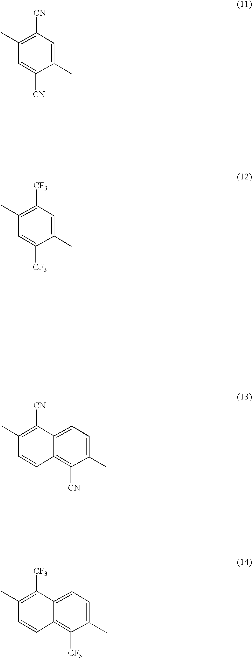
and Y1 and Y2 each may be a group represented by the following general formula (8) or (9). (the same shall apply hereinafter)

(where, in the general formulas (8) and (9) above, R11 and R12 are defined as above, R13 to R30 are defined as above (or a trifluoromethyl group if defined as fluoroalkyl groups).


(where, in the general formula above, R1 to R8 each denotes a hydrogen atom, substituted or unsubstituted alkyl group, substituted or unsubstituted aryl group, substituted or unsubstituted amino group, halogen atom, cyano group, or hydroxyl group.)


Claims (17)


Applications Claiming Priority (3)
| Application Number | Priority Date | Filing Date | Title |
|---|---|---|---|
| JP2000-106430 | 2000-04-07 | ||
| JP2000106430A JP2001291591A (en) | 2000-04-07 | 2000-04-07 | Organic electroluminescent element and light emitting device |
| PCT/JP2001/003051 WO2001077253A1 (en) | 2000-04-07 | 2001-04-09 | Organic electroluminescent element and luminescent apparatus employing the same |
Publications (2)
| Publication Number | Publication Date |
|---|---|
| US20020106530A1 US20020106530A1 (en) | 2002-08-08 |
| US7255935B2 true US7255935B2 (en) | 2007-08-14 |
Family
ID=18619599
Family Applications (1)
| Application Number | Title | Priority Date | Filing Date |
|---|---|---|---|
| US10/009,021 Expired - Fee Related US7255935B2 (en) | 2000-04-07 | 2001-04-09 | Organic electroluminescent element and luminescent apparatus employing the same |
Country Status (5)
| Country | Link |
|---|---|
| US (1) | US7255935B2 (en) |
| EP (1) | EP1205528A4 (en) |
| JP (1) | JP2001291591A (en) |
| KR (1) | KR100838094B1 (en) |
| WO (1) | WO2001077253A1 (en) |
Cited By (1)
| Publication number | Priority date | Publication date | Assignee | Title |
|---|---|---|---|---|
| US20130137206A1 (en) * | 2010-01-06 | 2013-05-30 | National Chiao Tung University | Organic light-emitting material, organic light-emitting element using the same and method of forming the same |
Families Citing this family (21)
| Publication number | Priority date | Publication date | Assignee | Title |
|---|---|---|---|---|
| WO2003091357A1 (en) * | 2000-10-30 | 2003-11-06 | Sony Corporation | Organic electroluminescent element |
| JP2002220355A (en) * | 2001-01-26 | 2002-08-09 | Matsushita Electric Ind Co Ltd | Aromatic methylidene compound, aromatic aldehyde compound and methylstyryl compound for producing the same, and methods for producing them |
| JP2002220354A (en) * | 2001-01-26 | 2002-08-09 | Matsushita Electric Ind Co Ltd | Aromatic methylidene compound, aromatic aldehyde compound and methylstyryl compound for producing the same, and methods for producing them |
| JP2002212113A (en) * | 2001-01-24 | 2002-07-31 | Matsushita Electric Ind Co Ltd | Aromatic methylidene compound, aromatic aldehyde compound and methylstyryl compound for producing the same, and methods for producing them |
| JP2002212114A (en) * | 2001-01-24 | 2002-07-31 | Matsushita Electric Ind Co Ltd | Aromatic methylidene compound, aromatic aldehyde compound and methylstyryl compound for producing the same, and methods for producing them |
| JP2002212115A (en) * | 2001-01-24 | 2002-07-31 | Matsushita Electric Ind Co Ltd | Aromatic methylidene compound, aromatic aldehyde compound and methylstyryl compound for producing the same, and methods for producing them |
| JP2004006066A (en) * | 2002-04-15 | 2004-01-08 | Sony Corp | Organic electroluminescent element and light emitting device |
| KR100495038B1 (en) | 2002-12-30 | 2005-06-14 | 엘지전자 주식회사 | Red color emitting compounds for organic electroluminescent device and organic electroluminescent device using them |
| JP4001118B2 (en) | 2003-03-24 | 2007-10-31 | ソニー株式会社 | Organic electroluminescent device and amino monostyryl naphthalene compound |
| CN100556224C (en) * | 2003-07-08 | 2009-10-28 | 柯尼卡美能达控股株式会社 | Organic electroluminescent element, lighting device and display device |
| US6885025B2 (en) * | 2003-07-10 | 2005-04-26 | Universal Display Corporation | Organic light emitting device structures for obtaining chromaticity stability |
| US7211823B2 (en) * | 2003-07-10 | 2007-05-01 | Universal Display Corporation | Organic light emitting device structure for obtaining chromaticity stability |
| KR100811058B1 (en) * | 2005-05-11 | 2008-03-06 | (주)루디스 | Light emitting polymer compound and organic light emitting device using the same |
| KR100707357B1 (en) * | 2005-06-23 | 2007-04-13 | (주)그라쎌 | Precursor Compounds of Organic Metal Complexes for Electroluminescent Materials |
| KR100736619B1 (en) * | 2005-10-12 | 2007-07-09 | 엘지전자 주식회사 | Organic light emitting diode |
| US7352125B2 (en) | 2005-12-21 | 2008-04-01 | Lg.Philips Lcd Co., Ltd. | Organic light emitting devices with hole impeding materials |
| WO2007132965A1 (en) * | 2006-05-12 | 2007-11-22 | Cheong-A Baek | High brightness electro luminescence device and method for manufacturing thereof |
| KR100924144B1 (en) | 2008-06-05 | 2009-10-28 | 삼성모바일디스플레이주식회사 | Organic electroluminescent device and manufacturing method thereof |
| TWI421230B (en) * | 2010-01-06 | 2014-01-01 | Univ Nat Chiao Tung | Organic light emitting element and method of forming the same |
| PT3533601T (en) * | 2018-03-01 | 2022-08-09 | Bayerische Motoren Werke Ag | Composite structure for an airbag cover and sewn product with the composite structure |
| CN109742251B (en) * | 2019-01-08 | 2022-05-13 | 京东方科技集团股份有限公司 | OLED device, display panel and display device |
Citations (15)
| Publication number | Priority date | Publication date | Assignee | Title |
|---|---|---|---|---|
| EP0388768A2 (en) | 1989-03-20 | 1990-09-26 | Idemitsu Kosan Company Limited | Organic electroluminescent device containing aromatic dimethylidyne compounds |
| JPH02247278A (en) | 1989-03-20 | 1990-10-03 | Idemitsu Kosan Co Ltd | Electroluminescence element |
| JPH061973A (en) | 1992-06-18 | 1994-01-11 | Konica Corp | Organic electroluminescent device |
| US5281489A (en) * | 1990-03-16 | 1994-01-25 | Asashi Kasei Kogyo Kabushiki Kaisha | Electroluminescent element |
| EP0929104A2 (en) | 1998-01-09 | 1999-07-14 | Sony Corporation | Electroluminescence device and process for producing the same |
| EP0954205A2 (en) | 1998-03-24 | 1999-11-03 | Sony Corporation | Organic eletroluminescent device and method for producing it |
| JPH11329731A (en) | 1998-05-18 | 1999-11-30 | Sony Corp | Organic electroluminescent device |
| EP0967834A2 (en) | 1998-06-26 | 1999-12-29 | Sony Corporation | Organic electroluminescent device |
| JP2000012224A (en) | 1998-06-26 | 2000-01-14 | Sony Corp | Organic electroluminescent device |
| EP1073128A2 (en) | 1999-07-30 | 2001-01-31 | Sony Corporation | Organic electroluminescent device |
| US6228514B1 (en) | 1998-06-26 | 2001-05-08 | Sony Corporation | Organic electroluminescent device |
| US20010033945A1 (en) | 1998-05-18 | 2001-10-25 | Tadashi Ishibashi | Organic electroluminescent device |
| US6492557B1 (en) * | 1999-10-06 | 2002-12-10 | Sony Corporation | Bis (aminostyryl) naphthalene compound, synthesis intermediate thereof, and process for production thereof |
| US6525212B1 (en) * | 1998-12-07 | 2003-02-25 | Sony Corporation | Bis(aminostyryl)benzene compounds and synthetic intermediates thereof, and process for preparing the compounds and intermediates |
| US6660411B2 (en) * | 2000-09-20 | 2003-12-09 | Mitsubishi Chemical Corporation | Organic electroluminescent device |
Family Cites Families (2)
| Publication number | Priority date | Publication date | Assignee | Title |
|---|---|---|---|---|
| JP3852509B2 (en) * | 1998-01-09 | 2006-11-29 | ソニー株式会社 | Electroluminescent device and manufacturing method thereof |
| JP4164718B2 (en) * | 1999-10-06 | 2008-10-15 | ソニー株式会社 | Bis (aminostyryl) naphthalene compound and synthetic intermediate thereof, production method thereof, and organic electroluminescent device |
-
2000
- 2000-04-07 JP JP2000106430A patent/JP2001291591A/en active Pending
-
2001
- 2001-04-09 US US10/009,021 patent/US7255935B2/en not_active Expired - Fee Related
- 2001-04-09 WO PCT/JP2001/003051 patent/WO2001077253A1/en not_active Ceased
- 2001-04-09 KR KR1020017015806A patent/KR100838094B1/en not_active Expired - Fee Related
- 2001-04-09 EP EP01919842A patent/EP1205528A4/en not_active Withdrawn
Patent Citations (19)
| Publication number | Priority date | Publication date | Assignee | Title |
|---|---|---|---|---|
| JPH02247278A (en) | 1989-03-20 | 1990-10-03 | Idemitsu Kosan Co Ltd | Electroluminescence element |
| EP0388768A2 (en) | 1989-03-20 | 1990-09-26 | Idemitsu Kosan Company Limited | Organic electroluminescent device containing aromatic dimethylidyne compounds |
| US5281489A (en) * | 1990-03-16 | 1994-01-25 | Asashi Kasei Kogyo Kabushiki Kaisha | Electroluminescent element |
| JPH061973A (en) | 1992-06-18 | 1994-01-11 | Konica Corp | Organic electroluminescent device |
| EP0929104A2 (en) | 1998-01-09 | 1999-07-14 | Sony Corporation | Electroluminescence device and process for producing the same |
| US6633122B2 (en) * | 1998-01-09 | 2003-10-14 | Sony Corporation | Electroluminescence device with multiple laminated bodies having common materials and process for producing the same |
| EP0954205A2 (en) | 1998-03-24 | 1999-11-03 | Sony Corporation | Organic eletroluminescent device and method for producing it |
| US20010033945A1 (en) | 1998-05-18 | 2001-10-25 | Tadashi Ishibashi | Organic electroluminescent device |
| JPH11329731A (en) | 1998-05-18 | 1999-11-30 | Sony Corp | Organic electroluminescent device |
| EP0960927A2 (en) | 1998-05-18 | 1999-12-01 | Sony Corporation | Organic electroluminescent device |
| EP0967834A2 (en) | 1998-06-26 | 1999-12-29 | Sony Corporation | Organic electroluminescent device |
| US6228514B1 (en) | 1998-06-26 | 2001-05-08 | Sony Corporation | Organic electroluminescent device |
| US6265088B1 (en) * | 1998-06-26 | 2001-07-24 | Sony Corporation | Organic electroluminescent device |
| JP2000012226A (en) | 1998-06-26 | 2000-01-14 | Sony Corp | Organic electroluminescent device |
| JP2000012224A (en) | 1998-06-26 | 2000-01-14 | Sony Corp | Organic electroluminescent device |
| US6525212B1 (en) * | 1998-12-07 | 2003-02-25 | Sony Corporation | Bis(aminostyryl)benzene compounds and synthetic intermediates thereof, and process for preparing the compounds and intermediates |
| EP1073128A2 (en) | 1999-07-30 | 2001-01-31 | Sony Corporation | Organic electroluminescent device |
| US6492557B1 (en) * | 1999-10-06 | 2002-12-10 | Sony Corporation | Bis (aminostyryl) naphthalene compound, synthesis intermediate thereof, and process for production thereof |
| US6660411B2 (en) * | 2000-09-20 | 2003-12-09 | Mitsubishi Chemical Corporation | Organic electroluminescent device |
Cited By (1)
| Publication number | Priority date | Publication date | Assignee | Title |
|---|---|---|---|---|
| US20130137206A1 (en) * | 2010-01-06 | 2013-05-30 | National Chiao Tung University | Organic light-emitting material, organic light-emitting element using the same and method of forming the same |
Also Published As
| Publication number | Publication date |
|---|---|
| EP1205528A4 (en) | 2004-10-27 |
| KR20020026873A (en) | 2002-04-12 |
| KR100838094B1 (en) | 2008-06-13 |
| WO2001077253A1 (en) | 2001-10-18 |
| JP2001291591A (en) | 2001-10-19 |
| US20020106530A1 (en) | 2002-08-08 |
| EP1205528A1 (en) | 2002-05-15 |
Similar Documents
| Publication | Publication Date | Title |
|---|---|---|
| US7255935B2 (en) | Organic electroluminescent element and luminescent apparatus employing the same | |
| JP4161262B2 (en) | ORGANIC ELECTROLUMINESCENT ELEMENT AND LIGHT EMITTING OR DISPLAY DEVICE USING THE SAME | |
| US6949878B2 (en) | Multicolor light emission apparatus with multiple different wavelength organic elements | |
| JP3852552B2 (en) | Organic electroluminescence device | |
| KR100751464B1 (en) | Organic electroluminescent device | |
| JP2000173774A (en) | Organic electroluminescent device | |
| JP2002134276A (en) | Organic electroluminescent device | |
| EP0960927B1 (en) | Organic electroluminescent device | |
| JP3820752B2 (en) | Organic electroluminescence device | |
| JP2000091073A (en) | Organic electroluminescent device | |
| US20050064232A1 (en) | Organic field emission device and emission device | |
| US6265088B1 (en) | Organic electroluminescent device | |
| JP3852517B2 (en) | Organic electroluminescence device | |
| EP0985719B1 (en) | Organic electroluminescent device | |
| JP2000012228A (en) | Organic electroluminescent device | |
| JP3852520B2 (en) | Organic electroluminescence device | |
| JP2000173773A (en) | Organic electroluminescent device | |
| JP2000091075A (en) | Organic electroluminescent device | |
| JP2000091074A (en) | Organic electroluminescent device | |
| JP2000091076A (en) | Organic electroluminescence element |
Legal Events
| Date | Code | Title | Description |
|---|---|---|---|
| AS | Assignment |
Owner name: SONY CORPORATION, JAPAN Free format text: ASSIGNMENT OF ASSIGNORS INTEREST;ASSIGNORS:ISHIBASHI, TADASHI;ICHIMURA, MARI;UEDA, NAOYUKI;AND OTHERS;REEL/FRAME:012722/0079;SIGNING DATES FROM 20020222 TO 20020225 |
|
| FEPP | Fee payment procedure |
Free format text: PAYOR NUMBER ASSIGNED (ORIGINAL EVENT CODE: ASPN); ENTITY STATUS OF PATENT OWNER: LARGE ENTITY |
|
| FPAY | Fee payment |
Year of fee payment: 4 |
|
| REMI | Maintenance fee reminder mailed | ||
| LAPS | Lapse for failure to pay maintenance fees | ||
| STCH | Information on status: patent discontinuation |
Free format text: PATENT EXPIRED DUE TO NONPAYMENT OF MAINTENANCE FEES UNDER 37 CFR 1.362 |
|
| STCH | Information on status: patent discontinuation |
Free format text: PATENT EXPIRED DUE TO NONPAYMENT OF MAINTENANCE FEES UNDER 37 CFR 1.362 |
|
| FP | Lapsed due to failure to pay maintenance fee |
Effective date: 20150814 |