EP1205528A1 - Organic electroluminescent element and luminescent apparatus employing the same - Google Patents
Organic electroluminescent element and luminescent apparatus employing the same Download PDFInfo
- Publication number
- EP1205528A1 EP1205528A1 EP01919842A EP01919842A EP1205528A1 EP 1205528 A1 EP1205528 A1 EP 1205528A1 EP 01919842 A EP01919842 A EP 01919842A EP 01919842 A EP01919842 A EP 01919842A EP 1205528 A1 EP1205528 A1 EP 1205528A1
- Authority
- EP
- European Patent Office
- Prior art keywords
- layer
- organic
- transfer layer
- electroluminescent element
- organic electroluminescent
- Prior art date
- Legal status (The legal status is an assumption and is not a legal conclusion. Google has not performed a legal analysis and makes no representation as to the accuracy of the status listed.)
- Withdrawn
Links
- -1 aminostyryl compound Chemical class 0.000 claims abstract description 244
- 230000027756 respiratory electron transport chain Effects 0.000 claims abstract description 217
- 238000012546 transfer Methods 0.000 claims abstract description 162
- 239000000203 mixture Substances 0.000 claims abstract description 133
- 230000000903 blocking effect Effects 0.000 claims abstract description 51
- 125000000449 nitro group Chemical group [O-][N+](*)=O 0.000 claims abstract description 21
- 125000001424 substituent group Chemical group 0.000 claims abstract description 21
- 125000003118 aryl group Chemical group 0.000 claims abstract description 18
- 239000010410 layer Substances 0.000 claims description 656
- 239000012044 organic layer Substances 0.000 claims description 103
- 125000003709 fluoroalkyl group Chemical group 0.000 claims description 24
- 125000004093 cyano group Chemical group *C#N 0.000 claims description 21
- 125000005843 halogen group Chemical group 0.000 claims description 21
- 125000000217 alkyl group Chemical group 0.000 claims description 17
- 125000004435 hydrogen atom Chemical group [H]* 0.000 claims description 17
- 125000003545 alkoxy group Chemical group 0.000 claims description 12
- 125000002023 trifluoromethyl group Chemical group FC(F)(F)* 0.000 claims description 5
- 239000000758 substrate Substances 0.000 abstract description 48
- 150000001875 compounds Chemical class 0.000 abstract description 37
- 229910052751 metal Inorganic materials 0.000 abstract description 23
- 239000002184 metal Substances 0.000 abstract description 23
- 239000011521 glass Substances 0.000 abstract description 16
- 125000001997 phenyl group Chemical group [H]C1=C([H])C([H])=C(*)C([H])=C1[H] 0.000 abstract 1
- 230000006866 deterioration Effects 0.000 description 110
- 239000012299 nitrogen atmosphere Substances 0.000 description 110
- 239000010408 film Substances 0.000 description 78
- 239000000463 material Substances 0.000 description 63
- 238000004519 manufacturing process Methods 0.000 description 58
- 238000005259 measurement Methods 0.000 description 55
- 238000000034 method Methods 0.000 description 55
- 238000010183 spectrum analysis Methods 0.000 description 55
- 238000000151 deposition Methods 0.000 description 53
- 230000008021 deposition Effects 0.000 description 53
- TVIVIEFSHFOWTE-UHFFFAOYSA-K tri(quinolin-8-yloxy)alumane Chemical compound [Al+3].C1=CN=C2C([O-])=CC=CC2=C1.C1=CN=C2C([O-])=CC=CC2=C1.C1=CN=C2C([O-])=CC=CC2=C1 TVIVIEFSHFOWTE-UHFFFAOYSA-K 0.000 description 52
- 230000015572 biosynthetic process Effects 0.000 description 42
- 238000001771 vacuum deposition Methods 0.000 description 41
- 125000005842 heteroatom Chemical group 0.000 description 20
- 0 Cc(cc1)ccc1N(c1ccccc1)c1ccc(*c2cc(C#N)c(CCc(cc3)ccc3N(c3ccccc3)c3ccc(C4=**4)cc3)cc2C#N)cc1 Chemical compound Cc(cc1)ccc1N(c1ccccc1)c1ccc(*c2cc(C#N)c(CCc(cc3)ccc3N(c3ccccc3)c3ccc(C4=**4)cc3)cc2C#N)cc1 0.000 description 17
- 229910052709 silver Inorganic materials 0.000 description 15
- 239000010409 thin film Substances 0.000 description 13
- 238000007740 vapor deposition Methods 0.000 description 13
- 239000000975 dye Substances 0.000 description 9
- 229910052782 aluminium Inorganic materials 0.000 description 6
- 239000011241 protective layer Substances 0.000 description 5
- 230000006798 recombination Effects 0.000 description 5
- 238000005215 recombination Methods 0.000 description 5
- XAGFODPZIPBFFR-UHFFFAOYSA-N aluminium Chemical compound [Al] XAGFODPZIPBFFR-UHFFFAOYSA-N 0.000 description 4
- 238000011161 development Methods 0.000 description 4
- 230000018109 developmental process Effects 0.000 description 4
- 238000002347 injection Methods 0.000 description 4
- 239000007924 injection Substances 0.000 description 4
- 239000011159 matrix material Substances 0.000 description 4
- 150000002894 organic compounds Chemical class 0.000 description 4
- 150000005041 phenanthrolines Chemical class 0.000 description 4
- XOLBLPGZBRYERU-UHFFFAOYSA-N tin dioxide Chemical compound O=[Sn]=O XOLBLPGZBRYERU-UHFFFAOYSA-N 0.000 description 4
- 239000007983 Tris buffer Substances 0.000 description 3
- 239000000956 alloy Substances 0.000 description 3
- 229910045601 alloy Inorganic materials 0.000 description 3
- 230000005540 biological transmission Effects 0.000 description 3
- 238000004768 lowest unoccupied molecular orbital Methods 0.000 description 3
- 229960003540 oxyquinoline Drugs 0.000 description 3
- MCJGNVYPOGVAJF-UHFFFAOYSA-N quinolin-8-ol Chemical compound C1=CN=C2C(O)=CC=CC2=C1 MCJGNVYPOGVAJF-UHFFFAOYSA-N 0.000 description 3
- 239000003086 colorant Substances 0.000 description 2
- 239000002019 doping agent Substances 0.000 description 2
- 238000004770 highest occupied molecular orbital Methods 0.000 description 2
- 229910052738 indium Inorganic materials 0.000 description 2
- 239000004973 liquid crystal related substance Substances 0.000 description 2
- 238000004020 luminiscence type Methods 0.000 description 2
- 150000002739 metals Chemical class 0.000 description 2
- 239000004033 plastic Substances 0.000 description 2
- 229920003023 plastic Polymers 0.000 description 2
- 238000006862 quantum yield reaction Methods 0.000 description 2
- 238000007789 sealing Methods 0.000 description 2
- 239000000126 substance Substances 0.000 description 2
- YLYPIBBGWLKELC-RMKNXTFCSA-N 2-[2-[(e)-2-[4-(dimethylamino)phenyl]ethenyl]-6-methylpyran-4-ylidene]propanedinitrile Chemical compound C1=CC(N(C)C)=CC=C1\C=C\C1=CC(=C(C#N)C#N)C=C(C)O1 YLYPIBBGWLKELC-RMKNXTFCSA-N 0.000 description 1
- KDECRJGIYVVZPG-UHFFFAOYSA-N CC(C)(C1)c2c(C)c(C#N)cc3c2N1CCC3(C)C Chemical compound CC(C)(C1)c2c(C)c(C#N)cc3c2N1CCC3(C)C KDECRJGIYVVZPG-UHFFFAOYSA-N 0.000 description 1
- RHACPKBDUNXOTR-XFXZXTDPSA-N CC(C1C2C1)=CC=C2N(c1ccccc1)c1ccc(/C=C\c(cc(c(C)c2)C#N)c2C#N)cc1 Chemical compound CC(C1C2C1)=CC=C2N(c1ccccc1)c1ccc(/C=C\c(cc(c(C)c2)C#N)c2C#N)cc1 RHACPKBDUNXOTR-XFXZXTDPSA-N 0.000 description 1
- JBTOBYFFOHORPS-UHFFFAOYSA-N CCCC(CC)C(C=C1)=CCC1N(c1ccccc1)c1ccc(C=C)cc1 Chemical compound CCCC(CC)C(C=C1)=CCC1N(c1ccccc1)c1ccc(C=C)cc1 JBTOBYFFOHORPS-UHFFFAOYSA-N 0.000 description 1
- OFDDALHUWQIVHV-CBIKUMSCSA-N COc(cc1)ccc1N(c1ccc(/C=C\c(cc(c(/C=C\c(cc2)ccc2N(c(cc2)ccc2OC)c(cc2)ccc2OC)c2)C#N)c2C#N)cc1)c(cc1)ccc1OC Chemical compound COc(cc1)ccc1N(c1ccc(/C=C\c(cc(c(/C=C\c(cc2)ccc2N(c(cc2)ccc2OC)c(cc2)ccc2OC)c2)C#N)c2C#N)cc1)c(cc1)ccc1OC OFDDALHUWQIVHV-CBIKUMSCSA-N 0.000 description 1
- KJYZXPZUKBZCGY-AXPXABNXSA-N COc(cc1)ccc1N(c1ccccc1)c1ccc(/C=C\c(cc(c(/C=C\c(cc2)ccc2N(c2ccccc2)c(cc2)ccc2OC)c2)C#N)c2C#N)cc1 Chemical compound COc(cc1)ccc1N(c1ccccc1)c1ccc(/C=C\c(cc(c(/C=C\c(cc2)ccc2N(c2ccccc2)c(cc2)ccc2OC)c2)C#N)c2C#N)cc1 KJYZXPZUKBZCGY-AXPXABNXSA-N 0.000 description 1
- AFYSMTXIPXNCIA-UHFFFAOYSA-N Cc(cc1)ccc1N(c1ccccc1)C1=CCCc2c1cccc2 Chemical compound Cc(cc1)ccc1N(c1ccccc1)C1=CCCc2c1cccc2 AFYSMTXIPXNCIA-UHFFFAOYSA-N 0.000 description 1
- VAOAZTTYDLJMMZ-UHFFFAOYSA-N Cc(cc1)ccc1N(c1ccccc1)c(cc1)ccc1N=C=CC#C Chemical compound Cc(cc1)ccc1N(c1ccccc1)c(cc1)ccc1N=C=CC#C VAOAZTTYDLJMMZ-UHFFFAOYSA-N 0.000 description 1
- GYXYDKUDIMYIMN-UHFFFAOYSA-N Cc1c(C(F)(F)F)cc(C=[IH])c(C(F)(F)F)c1 Chemical compound Cc1c(C(F)(F)F)cc(C=[IH])c(C(F)(F)F)c1 GYXYDKUDIMYIMN-UHFFFAOYSA-N 0.000 description 1
- VYZAMTAEIAYCRO-UHFFFAOYSA-N Chromium Chemical compound [Cr] VYZAMTAEIAYCRO-UHFFFAOYSA-N 0.000 description 1
- 125000003277 amino group Chemical group 0.000 description 1
- 150000004982 aromatic amines Chemical class 0.000 description 1
- 125000001246 bromo group Chemical group Br* 0.000 description 1
- 125000001309 chloro group Chemical group Cl* 0.000 description 1
- 229910052804 chromium Inorganic materials 0.000 description 1
- 239000011651 chromium Substances 0.000 description 1
- 239000004020 conductor Substances 0.000 description 1
- 239000000470 constituent Substances 0.000 description 1
- 238000010276 construction Methods 0.000 description 1
- 238000013461 design Methods 0.000 description 1
- 238000010586 diagram Methods 0.000 description 1
- 239000012769 display material Substances 0.000 description 1
- 238000005401 electroluminescence Methods 0.000 description 1
- 230000005281 excited state Effects 0.000 description 1
- 125000001153 fluoro group Chemical group F* 0.000 description 1
- PCHJSUWPFVWCPO-UHFFFAOYSA-N gold Chemical compound [Au] PCHJSUWPFVWCPO-UHFFFAOYSA-N 0.000 description 1
- 229910052737 gold Inorganic materials 0.000 description 1
- 239000010931 gold Substances 0.000 description 1
- 230000005283 ground state Effects 0.000 description 1
- 125000002887 hydroxy group Chemical group [H]O* 0.000 description 1
- AMGQUBHHOARCQH-UHFFFAOYSA-N indium;oxotin Chemical compound [In].[Sn]=O AMGQUBHHOARCQH-UHFFFAOYSA-N 0.000 description 1
- VOFUROIFQGPCGE-UHFFFAOYSA-N nile red Chemical compound C1=CC=C2C3=NC4=CC=C(N(CC)CC)C=C4OC3=CC(=O)C2=C1 VOFUROIFQGPCGE-UHFFFAOYSA-N 0.000 description 1
- 150000002902 organometallic compounds Chemical class 0.000 description 1
- 125000002080 perylenyl group Chemical group C1(=CC=C2C=CC=C3C4=CC=CC5=CC=CC(C1=C23)=C45)* 0.000 description 1
- 230000001681 protective effect Effects 0.000 description 1
- DNXIASIHZYFFRO-UHFFFAOYSA-N pyrazoline Chemical compound C1CN=NC1 DNXIASIHZYFFRO-UHFFFAOYSA-N 0.000 description 1
- 238000011160 research Methods 0.000 description 1
- 238000012827 research and development Methods 0.000 description 1
- 239000007787 solid Substances 0.000 description 1
- 238000002834 transmittance Methods 0.000 description 1
- 239000012780 transparent material Substances 0.000 description 1
Images


Classifications
-
- C—CHEMISTRY; METALLURGY
- C09—DYES; PAINTS; POLISHES; NATURAL RESINS; ADHESIVES; COMPOSITIONS NOT OTHERWISE PROVIDED FOR; APPLICATIONS OF MATERIALS NOT OTHERWISE PROVIDED FOR
- C09K—MATERIALS FOR MISCELLANEOUS APPLICATIONS, NOT PROVIDED FOR ELSEWHERE
- C09K11/00—Luminescent, e.g. electroluminescent, chemiluminescent materials
- C09K11/06—Luminescent, e.g. electroluminescent, chemiluminescent materials containing organic luminescent materials
-
- C—CHEMISTRY; METALLURGY
- C07—ORGANIC CHEMISTRY
- C07C—ACYCLIC OR CARBOCYCLIC COMPOUNDS
- C07C211/00—Compounds containing amino groups bound to a carbon skeleton
- C07C211/43—Compounds containing amino groups bound to a carbon skeleton having amino groups bound to carbon atoms of six-membered aromatic rings of the carbon skeleton
- C07C211/54—Compounds containing amino groups bound to a carbon skeleton having amino groups bound to carbon atoms of six-membered aromatic rings of the carbon skeleton having amino groups bound to two or three six-membered aromatic rings
-
- C—CHEMISTRY; METALLURGY
- C07—ORGANIC CHEMISTRY
- C07C—ACYCLIC OR CARBOCYCLIC COMPOUNDS
- C07C211/00—Compounds containing amino groups bound to a carbon skeleton
- C07C211/43—Compounds containing amino groups bound to a carbon skeleton having amino groups bound to carbon atoms of six-membered aromatic rings of the carbon skeleton
- C07C211/57—Compounds containing amino groups bound to a carbon skeleton having amino groups bound to carbon atoms of six-membered aromatic rings of the carbon skeleton having amino groups bound to carbon atoms of six-membered aromatic rings being part of condensed ring systems of the carbon skeleton
- C07C211/58—Naphthylamines; N-substituted derivatives thereof
-
- C—CHEMISTRY; METALLURGY
- C07—ORGANIC CHEMISTRY
- C07C—ACYCLIC OR CARBOCYCLIC COMPOUNDS
- C07C217/00—Compounds containing amino and etherified hydroxy groups bound to the same carbon skeleton
- C07C217/78—Compounds containing amino and etherified hydroxy groups bound to the same carbon skeleton having amino groups and etherified hydroxy groups bound to carbon atoms of six-membered aromatic rings of the same carbon skeleton
- C07C217/80—Compounds containing amino and etherified hydroxy groups bound to the same carbon skeleton having amino groups and etherified hydroxy groups bound to carbon atoms of six-membered aromatic rings of the same carbon skeleton having amino groups and etherified hydroxy groups bound to carbon atoms of non-condensed six-membered aromatic rings
- C07C217/82—Compounds containing amino and etherified hydroxy groups bound to the same carbon skeleton having amino groups and etherified hydroxy groups bound to carbon atoms of six-membered aromatic rings of the same carbon skeleton having amino groups and etherified hydroxy groups bound to carbon atoms of non-condensed six-membered aromatic rings of the same non-condensed six-membered aromatic ring
- C07C217/92—Compounds containing amino and etherified hydroxy groups bound to the same carbon skeleton having amino groups and etherified hydroxy groups bound to carbon atoms of six-membered aromatic rings of the same carbon skeleton having amino groups and etherified hydroxy groups bound to carbon atoms of non-condensed six-membered aromatic rings of the same non-condensed six-membered aromatic ring the nitrogen atom of at least one of the amino groups being further bound to a carbon atom of a six-membered aromatic ring
-
- C—CHEMISTRY; METALLURGY
- C07—ORGANIC CHEMISTRY
- C07C—ACYCLIC OR CARBOCYCLIC COMPOUNDS
- C07C255/00—Carboxylic acid nitriles
- C07C255/49—Carboxylic acid nitriles having cyano groups bound to carbon atoms of six-membered aromatic rings of a carbon skeleton
- C07C255/58—Carboxylic acid nitriles having cyano groups bound to carbon atoms of six-membered aromatic rings of a carbon skeleton containing cyano groups and singly-bound nitrogen atoms, not being further bound to other hetero atoms, bound to the carbon skeleton
-
- H—ELECTRICITY
- H05—ELECTRIC TECHNIQUES NOT OTHERWISE PROVIDED FOR
- H05B—ELECTRIC HEATING; ELECTRIC LIGHT SOURCES NOT OTHERWISE PROVIDED FOR; CIRCUIT ARRANGEMENTS FOR ELECTRIC LIGHT SOURCES, IN GENERAL
- H05B33/00—Electroluminescent light sources
- H05B33/12—Light sources with substantially two-dimensional radiating surfaces
- H05B33/14—Light sources with substantially two-dimensional radiating surfaces characterised by the chemical or physical composition or the arrangement of the electroluminescent material, or by the simultaneous addition of the electroluminescent material in or onto the light source
-
- H—ELECTRICITY
- H10—SEMICONDUCTOR DEVICES; ELECTRIC SOLID-STATE DEVICES NOT OTHERWISE PROVIDED FOR
- H10K—ORGANIC ELECTRIC SOLID-STATE DEVICES
- H10K50/00—Organic light-emitting devices
- H10K50/10—OLEDs or polymer light-emitting diodes [PLED]
- H10K50/11—OLEDs or polymer light-emitting diodes [PLED] characterised by the electroluminescent [EL] layers
-
- H—ELECTRICITY
- H10—SEMICONDUCTOR DEVICES; ELECTRIC SOLID-STATE DEVICES NOT OTHERWISE PROVIDED FOR
- H10K—ORGANIC ELECTRIC SOLID-STATE DEVICES
- H10K85/00—Organic materials used in the body or electrodes of devices covered by this subclass
- H10K85/60—Organic compounds having low molecular weight
- H10K85/631—Amine compounds having at least two aryl rest on at least one amine-nitrogen atom, e.g. triphenylamine
- H10K85/633—Amine compounds having at least two aryl rest on at least one amine-nitrogen atom, e.g. triphenylamine comprising polycyclic condensed aromatic hydrocarbons as substituents on the nitrogen atom
-
- C—CHEMISTRY; METALLURGY
- C09—DYES; PAINTS; POLISHES; NATURAL RESINS; ADHESIVES; COMPOSITIONS NOT OTHERWISE PROVIDED FOR; APPLICATIONS OF MATERIALS NOT OTHERWISE PROVIDED FOR
- C09K—MATERIALS FOR MISCELLANEOUS APPLICATIONS, NOT PROVIDED FOR ELSEWHERE
- C09K2211/00—Chemical nature of organic luminescent or tenebrescent compounds
- C09K2211/10—Non-macromolecular compounds
- C09K2211/1003—Carbocyclic compounds
- C09K2211/1011—Condensed systems
-
- C—CHEMISTRY; METALLURGY
- C09—DYES; PAINTS; POLISHES; NATURAL RESINS; ADHESIVES; COMPOSITIONS NOT OTHERWISE PROVIDED FOR; APPLICATIONS OF MATERIALS NOT OTHERWISE PROVIDED FOR
- C09K—MATERIALS FOR MISCELLANEOUS APPLICATIONS, NOT PROVIDED FOR ELSEWHERE
- C09K2211/00—Chemical nature of organic luminescent or tenebrescent compounds
- C09K2211/10—Non-macromolecular compounds
- C09K2211/1003—Carbocyclic compounds
- C09K2211/1014—Carbocyclic compounds bridged by heteroatoms, e.g. N, P, Si or B
-
- H—ELECTRICITY
- H10—SEMICONDUCTOR DEVICES; ELECTRIC SOLID-STATE DEVICES NOT OTHERWISE PROVIDED FOR
- H10K—ORGANIC ELECTRIC SOLID-STATE DEVICES
- H10K2102/00—Constructional details relating to the organic devices covered by this subclass
- H10K2102/10—Transparent electrodes, e.g. using graphene
- H10K2102/101—Transparent electrodes, e.g. using graphene comprising transparent conductive oxides [TCO]
- H10K2102/103—Transparent electrodes, e.g. using graphene comprising transparent conductive oxides [TCO] comprising indium oxides, e.g. ITO
-
- H—ELECTRICITY
- H10—SEMICONDUCTOR DEVICES; ELECTRIC SOLID-STATE DEVICES NOT OTHERWISE PROVIDED FOR
- H10K—ORGANIC ELECTRIC SOLID-STATE DEVICES
- H10K50/00—Organic light-emitting devices
- H10K50/10—OLEDs or polymer light-emitting diodes [PLED]
- H10K50/14—Carrier transporting layers
-
- H—ELECTRICITY
- H10—SEMICONDUCTOR DEVICES; ELECTRIC SOLID-STATE DEVICES NOT OTHERWISE PROVIDED FOR
- H10K—ORGANIC ELECTRIC SOLID-STATE DEVICES
- H10K59/00—Integrated devices, or assemblies of multiple devices, comprising at least one organic light-emitting element covered by group H10K50/00
-
- H—ELECTRICITY
- H10—SEMICONDUCTOR DEVICES; ELECTRIC SOLID-STATE DEVICES NOT OTHERWISE PROVIDED FOR
- H10K—ORGANIC ELECTRIC SOLID-STATE DEVICES
- H10K59/00—Integrated devices, or assemblies of multiple devices, comprising at least one organic light-emitting element covered by group H10K50/00
- H10K59/80—Constructional details
- H10K59/87—Passivation; Containers; Encapsulations
- H10K59/871—Self-supporting sealing arrangements
-
- H—ELECTRICITY
- H10—SEMICONDUCTOR DEVICES; ELECTRIC SOLID-STATE DEVICES NOT OTHERWISE PROVIDED FOR
- H10K—ORGANIC ELECTRIC SOLID-STATE DEVICES
- H10K85/00—Organic materials used in the body or electrodes of devices covered by this subclass
- H10K85/30—Coordination compounds
- H10K85/321—Metal complexes comprising a group IIIA element, e.g. Tris (8-hydroxyquinoline) gallium [Gaq3]
- H10K85/324—Metal complexes comprising a group IIIA element, e.g. Tris (8-hydroxyquinoline) gallium [Gaq3] comprising aluminium, e.g. Alq3
-
- H—ELECTRICITY
- H10—SEMICONDUCTOR DEVICES; ELECTRIC SOLID-STATE DEVICES NOT OTHERWISE PROVIDED FOR
- H10K—ORGANIC ELECTRIC SOLID-STATE DEVICES
- H10K85/00—Organic materials used in the body or electrodes of devices covered by this subclass
- H10K85/60—Organic compounds having low molecular weight
- H10K85/615—Polycyclic condensed aromatic hydrocarbons, e.g. anthracene
-
- Y—GENERAL TAGGING OF NEW TECHNOLOGICAL DEVELOPMENTS; GENERAL TAGGING OF CROSS-SECTIONAL TECHNOLOGIES SPANNING OVER SEVERAL SECTIONS OF THE IPC; TECHNICAL SUBJECTS COVERED BY FORMER USPC CROSS-REFERENCE ART COLLECTIONS [XRACs] AND DIGESTS
- Y10—TECHNICAL SUBJECTS COVERED BY FORMER USPC
- Y10S—TECHNICAL SUBJECTS COVERED BY FORMER USPC CROSS-REFERENCE ART COLLECTIONS [XRACs] AND DIGESTS
- Y10S428/00—Stock material or miscellaneous articles
- Y10S428/917—Electroluminescent
Definitions
- the present invention relates to an organic electroluminescent element (organic EL element) in which an organic layer having a luminescent region is arranged between an anode and a cathode, and also to a luminescent device (such as display device) in which the organic EL element is used.
- organic electroluminescent element organic EL element
- a luminescent device such as display device
- CRT Braun tubes
- liquid-crystal displays of active matrix drive type have been commercialized as light-weight, high-efficiency flat panel displays, they have a narrow viewing angle and need back light with a large power consumption when used in a dark environment (because they do not emit light spontaneously). Moreover, they are not satisfactory in response to high-speed, high-resolution video signals, which are expected to be put to practical use in near future. Another disadvantage is difficulties in production of large-screen displays and high production cost.
- the organic electroluminescent element is composed of a transparent anode and a metal cathode, with an organic thin film interposed between them, the organic thin film containing a luminous material which emits light upon current injection.
- C. W. Tang, S. A. VanSlyke, et al. reported in Applied Physics Letters, vol. 51, No. 12, pp. 913-915 (1987) the development of an organic EL element of single-hetero structure in which the organic thin film is of double-layer structure consisting of a thin film of hole-transfer material and a thin film of electron-transfer material, so that the organic thin film emits light by recombination of holes and electrons injected into it from the anode and cathode, respectively.
- either the hole transfer material or the electron transfer material functions also as a luminous material, and light emission takes place in the wavelength region corresponding to the energy gap at the ground state and excited state of the luminous material.
- the double-layer structure greatly reduces the drive voltage and improves the luminescence efficiency.
- the organic compound used as the luminous material is available in many kinds, and hence theoretically it will emit light of any desired color if its molecular structure is properly modified. It is easier to make an EL element with an organic compound than with an inorganic thin film, because an organic compound with proper molecular design produces high-purity three colors (red, green, and blue) necessary for the full-color display.
- red light is obtained from an electron transfer material which is tris (8-quinolinol) aluminum (Alq3 for short hereinafter) doped with DCM [4-dicyanomethylene-6-(p-dimethylaminostyryl)-2-methyl-4H-pyran]. (Chem. Funct. Dyes, Proc. Int. Symp., 2nd P. 536 (1993)) Unfortunately, it is not satisfactory in brightness and reliability for use as the display material.
- Japanese Patent Laid-open No. 188649/1995 Japanese Patent Application No. 148798/1994
- This compound is intended for blue color emission, not for red color emission.
- the present inventors carried out extensive studies, which led to the finding that it is possible to provide an organic electroluminescent element emitting red light with high luminance and high reliability if it has the light-emitting region composed of a specific aminostyryl compound and a material capable of transmitting energy efficiently to the compound.
- the present invention is directed to an organic electroluminescent element (occasionally referred to as the first organic EL element of the present invention hereinafter) in which an organic layer having a luminescent region is arranged between an anode and a cathode and an organic substance which emits light upon current injection is contained as a constituent, characterized in that said organic layer is constructed of at least one layer formed from a mixture containing at least one species of the aminostyryl compounds represented by the following general formula [I].
- an organic electroluminescent element (occasionally referred to as the first organic EL element of the present invention hereinafter) in which an organic layer having a luminescent region is arranged between an anode and a cathode and an organic substance which emits light upon current injection is contained as a constituent, characterized in that said organic layer is constructed of at least one layer formed from a mixture containing at least one species of the aminostyryl compounds represented by the following general formula [I].
- X 1 denotes any of the following general formulas (1) to (7) (where, in the general formulas (1) to (3) above, at least one (for example, one or two) of R 1 to R 4 is a group selected from halogen atoms (such as fluorine atoms, chlorine atoms, and bromine atoms, the same shall apply hereinafter), nitro groups, cyano groups, and fluoroalkyl groups (such as trifluoromethyl group, the same shall apply hereinafter), and others are groups selected from hydrogen atom, alkyl groups, aryl groups, alkoxyl groups, halogen atoms, nitro groups, cyano groups, and fluoroalkyl groups, which are identical or different; in the general formulas (4) to (7), at least one (for example, one or two) of R 5 to R 10 is a group selected from halogen atoms (such as fluorine atoms, chlorine atoms, and bromine atoms, the same shall apply hereinafter), nitro groups
- R 11 and R 12 each is a group selected from a hydrogen atom, alkyl groups with optional substituents, and aryl groups with optional substituents, which are identical or different; and R 13 to R 35 each is a group selected from a hydrogen atom, alkyl groups with optional substituents, and aryl groups with optional substituents, alkoxyl groups with optional substituents, halogen atoms, nitro groups, cyano groups, and fluoroalkyl groups, which are identical or different.
- X 1 is a group represented by any one of the following structural formulas (11) to (14) and Y 1 and Y 2 each may be a group represented by the following general formula (8) or (9). (the same shall apply hereinafter) (where, in the general formulas (8) and (9) above, R 11 and R 12 are defined as above, R 13 to R 30 are defined as above (or a trifluoromethyl group if defined as fluoroalkyl groups).
- the organic layer may be of organic multilayer structure composed of a hole transfer layer and an electron transfer layer, with at least the electron transfer layer in the organic multilayer structure being the layer of a mixture containing at least one species of the aminostyryl compounds represented by the general formula [I] above.
- the organic layer may be of organic multilayer structure composed of a hole transfer layer and an electron transfer layer, with at least the hole transfer layer in the organic multilayer structure being the layer of a mixture containing at least one species of the aminostyryl compounds represented by the general formula [I] above.
- the organic layer may be of organic multilayer structure composed of a hole transfer layer and an electron transfer layer, with the hole transfer layer being a layer of a mixture containing at least one species of the aminostyryl compounds represented by the general formula [I] above, and the electron transfer layer being the layer of a mixture containing at least one species of the aminostyryl compounds represented by the general formula [I] above.
- the organic layer may be of organic multilayer structure composed of a hole transfer layer, a luminescent layer, and an electron transfer layer, with at least the luminescent layer in the organic multilayer structure being the layer of a mixture containing at least one species of the aminostyryl compounds represented by the general formula [I] above.
- the material that can be used to form the mixture layer containing the aminostyryl compound include, in addition to the aminostyryl compound, hole transfer materials (such as aromatic amines), electron transfer materials (such as Alq 3 and pyrazoline), and a series of compounds generally used as a dopant for red light emission (such as DCM and its analogous compounds, porphylins, phthalocyanines, perylene compounds, Nile red, and squarilium compounds). The same shall apply hereinafter.
- Matture layer typically means a layer of a mixture of the above-mentioned aminostyryl compound and other compounds. It also means a layer of a mixture of two or more aminostyryl compounds included in the above-mentioned aminostyryl compounds. Such a mixture layer emits red light with desired luminance and chromaticity according to the combination of a plurality of compounds.
- the organic electroluminescent element of the present invention is suitable for a light-emitting device which is constructed for use as a display device. The same shall apply hereinafter.
- the present invention is also directed to an organic electroluminescent element (occasionally referred to as the second organic EL element of the present invention hereinafter) in which an organic layer having a luminescent region is arranged between an anode and a cathode, characterized in that said organic layer is constructed of at least one layer formed from a mixture containing at least one species (one, two or more species) of the aminostyryl compounds represented by the following structural formulas (15)-1 to (15)-12, (16)-1 to (16)-12, (17)-1 to (17)-6, and (18)-1 to (18)-6.
- the organic layer may be of organic multilayer structure composed of a hole transfer layer and an electron transfer layer, with at least the electron transfer layer in the organic multilayer structure being the layer of a mixture containing at least one species of the aminostyryl compounds.
- the organic layer may be of organic multilayer structure composed of a hole transfer layer and an electron transfer layer, with at least the hole transfer layer in the organic multilayer structure being the layer of a mixture containing at least one species of the aminostyryl compounds.
- the organic layer may be of organic multilayer structure composed of a hole transfer layer and an electron transfer layer, with the hole transfer layer being a layer of a mixture containing at least one species of the aminostyryl compounds mentioned above, and the electron transfer layer being the layer of a mixture containing at least one species of the aminostyryl compounds.
- the organic layer may be of organic multilayer structure composed of a hole transfer layer, a luminescent layer, and an electron transfer layer, with at least the luminescent layer in the organic multilayer structure being the layer of a mixture containing at least one species of the aminostyryl compounds.
- the organic layer may be constructed such that at least one layer therein is a layer of a mixture containing at least one species of the aminostyryl compounds and a dye emitting red light which has the emission maximum in a range of 600 nm or more (for example, 600-700 nm, the same shall apply hereinafter).
- the organic layer may be of organic multilayer structure composed of a hole transfer layer and an electron transfer layer, with said at least one layer in the laminate structure being the electron transfer layer.
- the organic layer may be of organic multilayer structure composed of a hole transfer layer and an electron transfer layer, with said at least one layer in the laminate structure being the hole transfer layer.
- the organic layer may be of organic multilayer structure composed of a hole transfer layer and an electron transfer layer, with the hole transfer layer being a layer of a mixture containing at least one species of the aminostyryl compounds and a dye emitting red light which has the emission maximum in a range of 600 nm or more, and the electron transfer layer being the layer of a mixture containing at least one species of the aminostyryl compounds and a dye emitting red light which has the emission maximum in a range of 600 nm or more.
- the organic layer may be of organic multilayer structure composed of a hole transfer layer, a luminescent layer, and an electron transfer layer, with the luminescent layer being the layer of a mixture containing at least one species of the aminostyryl compounds and a dye emitting red light which has the emission maximum in a range of 600 nm or more.
- the present invention is also directed to an organic electroluminescent element (occasionally referred to as the third organic EL element of the present invention hereinafter) in which an organic layer having a luminescent region is arranged between an anode and a cathode, characterized in that said organic layer is constructed of at least one layer formed from a light-emitting mixture containing at least one species (one, two, or more species) of the aminostyryl compounds represented by the general formula [I] above and there exists a hole blocking layer adjacent to (particularly in contact with) the cathode of the layer formed from a light-emitting mixture.
- an organic electroluminescent element (occasionally referred to as the third organic EL element of the present invention hereinafter) in which an organic layer having a luminescent region is arranged between an anode and a cathode, characterized in that said organic layer is constructed of at least one layer formed from a light-emitting mixture containing at least one species (one, two, or more species) of the amino
- the organic layer may be of organic multilayer structure composed of a hole transfer layer and an electron transfer layer, with at least the electron transfer layer in the organic multilayer structure being the layer of a mixture containing at least one species of the aminostyryl compounds represented by the general formula [I] above.
- the organic layer may be of organic multilayer structure composed of a hole transfer layer and an electron transfer layer, with at least the hole transfer layer in the organic multilayer structure being the layer of a mixture containing at least one species of the aminostyryl compounds represented by the general formula [I] above.
- the organic layer may be of organic multilayer structure composed of a hole transfer layer and an electron transfer layer, with the hole transfer layer being the layer of a light-emitting mixture containing at least one species of the aminostyryl compounds represented by the general formula [I] above, and the electron transfer layer being the layer of a light-emitting mixture containing at least one species of the aminostyryl compounds represented by the general formula [I] above, and there exists a hole blocking layer adjacent to the cathode of the layer formed from a light-emitting mixture capable of electron transfer.
- the organic layer may be of organic multilayer structure composed of a hole transfer layer, a luminescent layer, and an electron transfer layer, with at least the luminescent layer in the organic multilayer structure being the layer of a light-emitting mixture containing at least one species of the aminostyryl compounds represented by the general formula [I] above.
- the hole blocking layer should be one which promotes the recombination of holes and electrons in the luminescent layer, thereby efficiently emitting light with high luminance.
- the material suitable for such a hole blocking layer should preferably be one which has the following energy state. That is, the highest occupied molecular orbital level of the material forming the hole blocking layer is at a lower energy level than the highest occupied molecular orbital level of the material forming the layer in contact with the anode of the hole blocking layer.
- the lowest unoccupied molecular orbital level of the material forming the hole blocking layer is at a higher energy level than the lowest unoccupied molecular orbital level of the material forming the layer in contact with the anode of the hole blocking layer and is also at a lower energy level than the lowest unoccupied molecular orbital level of material forming the layer in contact with the cathode of the hole blocking layer.
- Such materials include those phenanthroline derivatives which are disclosed in Japanese Patent Laid-open Nos. 79297/1998, 204258/1999, 204264/1999, and 204259/1999. They are not restricted to phenanthroline derivatives so long as they meet the above-mentioned condition of energy level. Those phenanthroline derivatives which can be used are shown below.
- R 1 to R 8 each denotes a hydrogen atom, substituted or unsubstituted alkyl group, substituted or unsubstituted aryl group, substituted or unsubstituted amino group, halogen atom, cyano group, or hydroxyl group.
- the present invention is directed to an organic electroluminescent element (occasionally referred to as the fourth organic EL element hereinafter) in which an organic layer having a luminescent region is arranged between an anode and a cathode, characterized in that said organic layer is constructed of at least one layer formed from a mixture containing at least one species (one, two, or more) of the aminostyryl compounds represented by the above-mentioned structural formulas (15)-1 to (15)-12, (16)-1 to (16)-12, (17)-1 to (17)-6, and (18)-1 to (18)-6, and there exists a hole blocking layer adjacent to the cathode of the layer formed from a light-emitting mixture.
- the organic layer may be of organic multilayer structure composed of a hole transfer layer and an electron transfer layer, with at least the electron transfer layer in the organic multilayer structure being the layer of a light-emitting mixture containing at least one species of the aminostyryl compounds.
- the organic layer may be of organic multilayer structure composed of a hole transfer layer and an electron transfer layer, with at least the hole transfer layer in the organic multilayer structure being a layer of a light-emitting mixture containing at least one species of the aminostyryl compounds.
- the organic layer may be of organic multilayer structure composed of a hole transfer layer and an electron transfer layer, with the hole transfer layer being a layer of a light-emitting mixture containing at least one species of the aminostyryl compounds, and the electron transfer layer being the layer of a light-emitting mixture containing at least one species of the aminostyryl compounds, and there exists a hole blocking layer adjacent to the cathode of the layer formed from a light-emitting mixture capable of electron transfer.
- the organic layer may be of organic multilayer structure composed of a hole transfer layer, a luminescent layer, and an electron transfer layer, with at least the luminescent layer in the organic multilayer structure being a layer of a light-emitting mixture containing at least one species of the aminostyryl compounds mentioned above.
- the organic layer may be constructed such that said at least one layer therein is the layer of a light-emitting mixture containing at least one species of the aminostyryl compounds and a dye emitting red light which has the emission maximum in a range of 600 nm or more.
- the organic layer may be of organic multilayer structure composed of a hole transfer layer and an electron transfer layer, with said at least one layer in the laminate structure being the electron transfer layer.
- the organic layer may be of organic multilayer structure composed of a hole transfer layer and an electron transfer layer, with said at least one layer in the laminate structure being the hole transfer layer.
- the organic layer may be of organic multilayer structure composed of a hole transfer layer and an electron transfer layer, with the hole transfer layer being the layer of a light-emitting mixture containing at least one species of the aminostyryl compounds and a dye emitting red light which has the emission maximum in the region beyond 600 nm, and the electron transfer layer being a layer of a light-emitting mixture containing at least one species of the aminostyryl compounds and a dye emitting red light which has the emission maximum in a range of 600 nm or more, and there exists a hole blocking layer adjacent to the cathode of the layer formed from a light-emitting mixture capable of electron transfer.
- the hole transfer layer being the layer of a light-emitting mixture containing at least one species of the aminostyryl compounds and a dye emitting red light which has the emission maximum in the region beyond 600 nm
- the electron transfer layer being a layer of a light-emitting mixture containing at least one species of the aminostyryl compounds and
- the organic layer may be of organic multilayer structure composed of a hole transfer layer, a luminescent layer, and an electron transfer layer, with the luminescent layer being the layer of a light-emitting mixture containing at least one species of the aminostyryl compounds and a dye emitting red light which has the emission maximum in a range of 600 nm or more.
- the present invention is also directed to an organic electroluminescent element (occasionally referred to as the fifth organic EL element of the present invention hereinafter) in which an organic layer having a luminescent region is arranged between an anode and a cathode, characterized in that said organic layer is constructed of at least one layer formed from a aminostyryl compound represented by the above-mentioned general formula [I] and there exists a hole blocking layer adjacent to (particularly in contact with) the cathode of the layer of aminostyryl compound.
- a aminostyryl compound represented by the above-mentioned general formula [I]
- the organic layer may be of organic multilayer structure composed of a hole transfer layer and an electron transfer layer, with at least the electron transfer layer in the organic multilayer structure being a layer of said aminostyryl compound.
- the organic layer may be of organic multilayer structure composed of a hole transfer layer and an electron transfer layer, with at least the hole transfer layer in the organic multilayer structure being the layer of said aminostyryl compound.
- the organic layer may be of organic multilayer structure composed of a hole transfer layer and an electron transfer layer, with the hole transfer layer being the layer of the aminostyryl compound, and the electron transfer layer being the layer of the aminostyryl compound, and there exists the hole blocking layer adjacent to the cathode of the layer of aminostyryl compound capable of electron transfer.
- the organic layer may be of organic multilayer structure composed of a hole transfer layer, a luminescent layer, and an electron transfer layer, with at least the luminescent layer in the organic multilayer structure being the layer of the aminostyryl compound.
- the hole blocking layer may be constructed in the same way as that in the third organic EL element of the present invention.
- the present invention is also directed to an organic electroluminescent element (occasionally referred to as the sixth organic element of the present invention) in which an organic layer having a luminescent region is arranged between an anode and a cathode, characterized in that said organic layer is constructed of at least one layer formed solely from an aminostyryl compound selected from the aminostyryl compounds represented by the above-mentioned structural formulas (15)-1 to (15)-12, (16)-1 to (16)-12, (17)-1 to (17)-6, and (18)-1 to (18)-6, and there exists a hole blocking layer adjacent to the cathode of the layer of said aminostyryl compound.
- an organic electroluminescent element (occasionally referred to as the sixth organic element of the present invention) in which an organic layer having a luminescent region is arranged between an anode and a cathode, characterized in that said organic layer is constructed of at least one layer formed solely from an aminostyryl compound selected from the aminostyryl compounds represented by the
- the organic layer may be of organic multilayer structure composed of a hole transfer layer and an electron transfer layer, with at least the electron transfer layer in the organic multilayer structure being the layer of said aminostyryl compound.
- the organic layer may be of organic multilayer structure composed of a hole transfer layer and an electron transfer layer, with at least the hole transfer layer in the organic multilayer structure being the layer of said aminostyryl compound.
- the organic layer many be of organic multilayer structure composed of a hole transfer layer and an electron transfer layer, with the hole transfer layer being the layer of the aminostyryl compound, and the electron transfer layer being the layer of the aminostyryl compound, and there exists the hole blocking layer adjacent to the cathode of the layer of aminostyryl compound capable of electron transfer.
- the organic layer may be of organic multilayer structure composed of a hole transfer layer, a luminescent layer, and an electron transfer layer, with at least the luminescent layer in the organic multilayer structure being the layer of the aminostyryl compound.
- Figs. 1 to 9 show the examples of the organic electroluminescent element (organic EL element) pertaining to the present invention.
- Fig. 1 shows a transmission-type organic electroluminescent element A which is constructed such that the emitted light 20 passes through the cathode 3. The emitted light 20 is also visible from the side of the protective layer 4.
- Fig. 2 shows a reflection-type organic electroluminescent element B which is constructed such that the emitted light 20 is reflected by the cathode 3.
- a substrate 1 on which is formed the organic electroluminescent element It may be made of glass, plastics, or any other appropriate material. In the case where the organic electroluminescent element is used in combination with any other display element; the substrate may be used in common.
- a transparent electrode (anode) 2 which may be made of ITO (indium tin oxide) or SnO 2 .
- an organic luminescent layer 5 which contains the above-mentioned aminostyryl compound as a luminescent material.
- the aminostyryl compound may be used individually in combination with any other compound or more than one kind of aminostyryl compound may be used in combination with one another. The same shall apply hereinafter.
- the organic luminescent layer capable of obtaining organic electroluminescent light 20 may have any known layer construction. In the case where either of the hole transfer layer or the electron transfer layer is formed from a luminescent material, the luminescent layer may be formed from thin layers placed one over another, as explained later.
- Both or either of the hole transfer layer and the electron transfer layer may be of laminate structure composed of thin films of a plurality of materials or may be a thin film composed of a plurality of materials.
- This structure may be used to increase the charge transfer performance to such an extent as to meet the object of the present invention.
- Another layer structure that can be used to increase the luminescent performance includes one in which a thin film of at least one kind of fluorescent material is interposed between the hole transfer layer and the electron transfer layer, or one in which at least one kind of fluorescent material is contained in both the hole transfer layer and the electron transfer layer.
- the layer structure may contain an additional thin film to control the hole transfer or electron transfer, thereby improving the luminescence efficiency.
- the aminostyryl compound represented by the above-mentioned general formula [1] is capable of both electron transfer and hole transfer; therefore, it can be used as the light-emitting layer which functions also as the electron transfer layer or as the light-emitting layer which functions also as the hole transfer layer.
- the electroluminescent element may be constructed such that the light-emitting layer (which is formed from said compound) is interposed between the electron transfer layer and the hole transfer layer.
- a cathode 3 In Figs. 1 and 2, there is shown a cathode 3.
- the cathode may be formed from an alloy of active metal (such as Li, Mg, and Ca) and metal (such as Ag, Al, and In), or may be formed from layers of these metals.
- active metal such as Li, Mg, and Ca
- metal such as Ag, Al, and In
- the cathode may have an adequate thickness so that a desired light transmittance is attained for specific uses.
- a sealing/protective layer 4 which entirely covers the organic electroluminescent element to ensure its performance. It can be formed from any material which maintains air tightness.
- the organic electroluminescent element according to the present invention may have an organic layer of laminate structure (or single-hetero structure) which is composed of a hole transfer layer and an electron transfer layer.
- the hole transfer layer or the electron transfer layer may be formed from a mixture containing the above-mentioned aminostyryl compound.
- the organic layer may be of double-hetero structure, in which a hole transfer layer, a luminescent layer, and an electron transfer layer are sequentially laminated on top of the other.
- the luminescent layer is formed from a mixture containing the above-mentioned aminostyryl compound.
- FIG. 3 An embodiment of the organic electroluminescent element of organic multilayer structure as mentioned above is illustrated in Fig. 3. It consists of a transparent substrate 1, a transparent anode 2, an organic layer 5a (composed of a hole transfer layer 6 and an electron transfer layer 7), and a cathode 3, which are sequentially placed on top of the other. The entire laminate structure is sealed with a protective layer 4. (Organic electroluminescent element C of single-hetero structure)
- the element of layer structure shown in Fig. 3 (in which the luminescent layer is omitted) emits light 20 of desired wavelength from the interface between the hole transfer layer 6 and the electron transfer layer 7. The emitted light is visible through the substrate 1.
- An embodiment of laminate structure shown in Fig. 4 consists of a transparent substrate 1, a transparent anode 2, an organic layer 5b (composed of a hole transfer layer 10; a luminescent layer 11, and an electron transfer layer 12), and a cathode 3, which are sequentially placed on top of the other.
- the entire laminate structure is sealed with a protective layer 4.
- Organic electroluminescent element D of double-hetero structure Organic electroluminescent element D of double-hetero structure
- the organic electroluminescent element shown in Fig. 4 works as follows.
- a dc voltage applied across the anode 2 and the cathode 3 causes holes (injected from the anode 2) to reach the luminescent layer 11 through the hole transfer layer 10 and also causes electrons (injected from the cathode 3) to reach the luminescent layer 11 through the electron transfer layer 12.
- holes injected from the anode 2
- electrons injected from the cathode 3
- recombination of electrons and holes takes place in the luminescent layer 11, thereby giving rise to singlet excitons which emit light of desired wavelength.
- the substrate 1 may be formed from any transparent material such as glass and plastics. If this element is used in combination with other display element or if the elements of laminate structure as shown in Figs. 3 and 4 are arranged in a matrix, one substrate may be used in common. Also, the elements C and D may be either of transmission type or of reflection type.
- the anode 2 is a transparent electrode, which may be made of ITO or SnO 2 .
- a thin film of organic substance or organometallic compound may be interposed between the anode 2 and the hole transfer layer 6 (or 10) for improvement in the charge injection efficiency.
- the protective film 4 is made of an electrically conductive material such as metal, then the anode 2 may be surrounded by an insulating film.
- the organic layer 5a is composed of the hole transfer layer 6 and the electron transfer layer 7, and the above-mentioned aminostyryl compound is contained in either of them. In this case, the hole transfer layer 6 or the electron transfer layer 7 emits light.
- the organic layer 5b is composed of the hole transfer layer 10, the luminescent layer 11 (containing the above-mentioned aminostyryl compound), and the electron transfer layer 12 which are laminated on top of the other.
- the layer structure may be modified in any other way. For example, either or both of the hole transfer layer and the electron transfer layer may emit light.
- the hole transfer layer may be constructed of laminate of several kinds of hole transfer materials for improvement in the hole transfer performance.
- the luminescent layer may be the electron transferring luminescent layer 7. In this case, light is emitted from the hole transfer layer 6 or the interface thereof depending on voltage applied from the power source 8.
- the electron transfer layer 12 or the hole transfer layer 10 may also function as the luminescent layer 11.
- a desirable structure for improved luminescent performance is such that a luminescent layer 11 containing at least one kind of fluorescent material is interposed between the hole transfer layer 11 and the electron transfer layer 12.
- the fluorescent material may be contained in either or both of the hole transfer layer and the electron transfer layer.
- the layer structure may contain a thin film (such as hole blocking layer and exciton generating layer) to control the transfer of holes or electrons for improvement in the light-emitting performance.
- the cathode 3 may be formed from an alloy of active metal (such as Li, Mg, and Ca) and metal (such as Ag, Al, and In). These metals may be used in the form of laminate layers. The thickness and material of the cathode should be properly selected according to the use of the organic electroluminescent element.
- the protective layer 4 functions as a sealing film. It should cover the organic electroluminescent element entirely so as to improve the charge injection efficiency and the light-emitting efficiency. It may be formed from any material (such as aluminum, gold, and chromium in the form of metal or alloy) so long as it keeps air tightness.
- organic electroluminescent elements work upon application of direct current. However, they may be operated by pulse current or alternating current. The magnitude of current and voltage is not specifically restricted so long as the element is not broken. It is desirable that the element emits light efficiency with a small amount of electric energy in view of the power consumption and life of the organic electroluminescent elements.
- the organic EL elements A to D shown in Figs. 1 to 4 may be modified as shown in Figs. 5 to 9 (designated by A' to D', respectively). They have a hole blocking layer 30 adjacent to the luminescent layer 5, the hole transfer layer 6, the electron transfer layer 7, or the luminescent layer 11 (the side facing the cathode 3).
- the above-mentioned aminostyryl compound may be used individually in combination with any other compound or more than one kind of aminostyryl compound may be used in combination with one another, or a single aminostyryl compound may form the layer.
- the organic electroluminescent elements of the present invention may be used to construct a flat display as shown in Fig. 10.
- the organic layer 5 (5a, 5b), each capable of emitting primary color of red (R), green (G), and blue (B), are interposed between the cathode 3 and the anode 2.
- the cathode 3 and anode 2 may be stripes intersecting each other.
- Each element is selected by the luminance signal circuit 14 and the control circuit 15 having a shift register. A signal voltage is applied according to the selection, so that the organic layer (pixel) at the intersection of the selected cathode 3 and anode 2 emits light.
- FIG. 10 An embodiment of simple matrix (8 ⁇ 3 RGB) is shown in Fig. 10. It is constructed such that a laminate 5 is interposed between the cathode 3 and the anode 2. This laminate is composed of the hole transfer layer and at least either of the luminescent layer and the electron transfer layer. (See Figs. 3 or 4.) Both the cathode and the anode are patterned in stripe form so that they intersect each other at right angles. Signal voltage is applied sequentially by the control circuits 15 (with a shift register) and the luminance signal circuit 14. The element at the intersection emits light. The EL element constructed in this way can be used as a display for characters and signs and it can also be used as an image reproducing apparatus. If the stripe pattern of the cathode 3 and anode 2 is arranged for each of red (R), green (G), and blue (B) colors, a multi-color or full-color solid flat display panel can be constructed.
- R red
- G green
- B blue
- This example demonstrates the production of an organic electroluminescent element of single hetero structure in which the luminescent layer capable of hole transfer is made of a mixture of an aminostyryl compound represented by the following structural formula (15)-3 and a-NPD (a-naphthylphenyldiamine).
- the former is one of the aminostyryl compounds represented by the above-mentioned general formula [I].
- the process was started by setting in a vacuum vapor deposition apparatus a glass substrate (30 ⁇ 30 mm) having a 100-nm thick anode of ITO formed on one side thereof.
- the substrate was covered with a metal mask having a plurality of unit openings each measuring 2.0 ⁇ 2.0 mm.
- a 50-nm thick hole transfer layer (functioning also as a luminescent layer) consisting of the two components in a ratio of 1:1 by weight.
- the rate of deposition was 0.1 nm/sec.
- the cathode in laminate structure was formed from Mg and Ag by vacuum deposition.
- the Mg film was 50 nm thick and the Ag film was 150 nm thick.
- the rate of deposition was 1 nm/sec.
- the organic electroluminescent element of Example 1 produced in this manner was examined for luminescent characteristics by applying a forward bias dc voltage in a nitrogen atmosphere. It emitted red light.
- a forward bias dc voltage in a nitrogen atmosphere. It emitted red light.
- the emitted light was found to have the luminescent peak at about 630 nm.
- the emitted light was found to have a luminance of 2000 cd/m 2 at 8V according to the measurements of luminance at various voltages.
- the organic electroluminescent element was allowed to stand for one month in a nitrogen atmosphere after it had been produced. It remained intact without any sign of deterioration. For accelerated deterioration, the element with an initial luminance of 200 cd/m 2 was allowed to emit light continuously by application of constant current. It took 900 hours for the element to decrease in luminance by half.
- This example demonstrates the production of an organic electroluminescent element of single hetero structure in which the luminescent layer capable of electron transfer is made of a mixture of an aminostyryl compound represented by the above-mentioned structural formula (15)-3 and Alq 3 .
- the former is one of the aminostyryl compounds represented by the above-mentioned general formula [I].
- the process was started by setting in a vacuum vapor deposition apparatus a glass substrate (30 ⁇ 30 mm) having a 100-nm thick anode of ITO formed on one side thereof.
- the substrate was covered with a metal mask having a plurality of unit openings each measuring 2.0 ⁇ 2.0 mm.
- a-NPD by vacuum deposition (at 10 -4 Pa or less) to form a 50-nm thick film.
- the rate of deposition was 0.1 nm/sec.
- the cathode in laminate structure was formed from Mg and Ag by vacuum deposition.
- the Mg film was 50 nm thick and the Ag film was 150 nm thick.
- the rate of deposition was 1 nm/sec.
- Example 2 The organic electroluminescent element of Example 2 produced in this manner was examined for luminescent characteristics by applying a forward bias dc voltage in a nitrogen atmosphere. It emitted red light. By spectral analysis in the same way as in Example 1, the emitted light was found to have the luminescent peak at about 630 nm. In addition, the emitted light was found to have a luminance of 1200 cd/m 2 at 8V according to the measurements of luminance at various voltages.
- the organic electroluminescent element was allowed to stand for one month in a nitrogen atmosphere after it had been produced. It remained intact without any sign of deterioration. For accelerated deterioration, the element with an initial luminance of 200 cd/m 2 was allowed to emit light continuously by application of constant current. It took 800 hours for the element to decrease in luminance by half.
- This example demonstrates the production of an organic electroluminescent element of double hetero structure in which the luminescent layer capable of electron transfer is made of a mixture of an aminostyryl compound represented by the above-mentioned structural formula (15)-3 and Alq 3 .
- the former is one of the aminostyryl compounds represented by the above-mentioned general formula [I].
- the process was started by setting in a vacuum vapor deposition apparatus a glass substrate (30 ⁇ 30 mm) having a 100-nm thick anode of ITO formed on one side thereof.
- the substrate was covered with a metal mask having a plurality of unit openings each measuring 2.0 ⁇ 2.0 mm.
- a-NPD by vacuum deposition (at 10 -4 Pa or less) to form a 30-nm thick film.
- the rate of deposition was 0.2 nm/sec.
- the luminescent layer was formed a 30 nm thick electron transfer layer by vacuum deposition from Alq 3 .
- the rate of deposition was 0.2 nm/sec.
- the cathode in laminate structure was formed from Mg and Ag by vacuum deposition.
- the Mg film was 50 nm thick and the Ag film was 150 nm thick.
- the rate of deposition was 1 nm/sec.
- the organic electroluminescent element produced in this manner was examined for luminescent characteristics by applying a forward bias dc voltage in a nitrogen atmosphere. It emitted red light. By spectral analysis in the same way as in Example 1, the emitted light was found to have the luminescent peak at about 630 nm. In addition, the emitted light was found to have a luminance of 2500 cd/m 2 at 8V according to the measurements of luminance at various voltages.
- the organic electroluminescent element was allowed to stand for one month in a nitrogen atmosphere after it had been produced. It remained intact without any sign of deterioration.
- the element with an initial luminance of 200 cd/m 2 was allowed to emit light continuously by application of constant current. It took 1500 hours for the element to decrease in luminance by half.
- This example demonstrates the production of an organic electroluminescent element of double hetero structure in which the luminescent layer is made of a mixture of an aminostyryl compound represented by the above-mentioned structural formula (15)-3 and an aminostyryl compound represented by the following structural formula (15)-1.
- the former is one of the aminostyryl compounds represented by the above-mentioned general formula [I].
- the process was started by setting in a vacuum vapor deposition apparatus a glass substrate (30 ⁇ 30 mm) having a 100-nm thick anode of ITO formed on one side thereof.
- the substrate was covered with a metal mask having a plurality of unit openings each measuring 2.0 ⁇ 2.0 mm.
- a-NPD by vacuum deposition (at lower than 10 -4 Pa) to form a 30-nm thick film.
- the rate of deposition was 0.2 nm/sec.
- a 30-nm thick luminescent layer consisting of the aminostyryl compound of structural formula (15)-3 and the aminostyryl compound of structural formula (15)-1.
- the rate of deposition was 0.1 nm/sec for the former compound and 0.3 nm/sec for the latter compound.
- the luminescent layer was formed a 30-nm thick electron transfer layer by vacuum deposition from Alq 3 .
- the rate of deposition was 0.2 nm/sec.
- the cathode in laminate structure was formed from Mg and Ag by vacuum deposition.
- the Mg film was 50 nm thick and the Ag film was 150 nm thick.
- the rate of deposition was 1 nm/sec.
- the organic electroluminescent element of Example 3 produced in this manner was examined for luminescent characteristics by applying a forward bias dc voltage in a nitrogen atmosphere. It emitted red light. By spectral analysis in the same way as in Example 1, the emitted light was found to have the luminescent peak at about 640 nm. In addition, the emitted light was found to have a luminance of 3000 cd/m 2 at 8V according to the measurements of luminance at various voltages.
- the organic electroluminescent element was allowed to stand for one month in a nitrogen atmosphere after it had been produced. It remained intact without any sign of deterioration.
- the element with an initial luminance of 200 cd/m 2 was allowed to emit light continuously by application of constant current. It took 1200 hours for the element to decrease in luminance by half.
- This example demonstrates the production of an organic electroluminescent element of single hetero structure in which the luminescent layer capable of electron transfer is made of a mixture of an aminostyryl compound represented by the above-mentioned structural formula (15)-3 and DCM represented by the following structural formula.
- the former is one of the aminostyryl compounds represented by the above-mentioned general formula [I].
- the process was started by setting in a vacuum vapor deposition apparatus a glass substrate (30 ⁇ 30 mm) having a 100-nm thick anode of ITO formed on one side thereof.
- the substrate was covered with a metal mask having a plurality of unit openings each measuring 2.0 ⁇ 2.0 mm.
- a-NPD of the above-mentioned structure by vacuum deposition (at 10 -4 Pa or less) to form a 50-nm thick film.
- the rate of deposition was 0.1 nm/sec.
- a 50-nm thick electron transfer layer (which functions also as the luminescent layer) consisting of the aminostyryl compound of structural formula (15)-3 and the above-mentioned DCM.
- the rate of deposition was 0.5 nm/sec for the former compound and 0.05 nm/sec for the latter compound.
- the cathode in laminate structure was formed from Mg and Ag by vacuum deposition.
- the Mg film was 50 nm thick and the Ag film was 150 nm thick.
- the rate of deposition was 1 nm/sec.
- the organic electroluminescent element of Example 5 produced in this manner was examined for luminescent characteristics by applying a forward bias dc voltage in a nitrogen atmosphere. It emitted red light. By spectral analysis in the same way as in Example 1, the emitted light was found to have the luminescent peak at about 630 nm. In addition, the emitted light was found to have a luminance of 800 cd/m 2 at 8V according to the measurements of luminance at various voltages.
- the organic electroluminescent element was allowed to stand for one month in a nitrogen atmosphere after it had been produced. It remained intact without any sign of deterioration. For accelerated deterioration, the element with an initial luminance of 200 cd/m 2 was allowed to. emit light continuously by application of constant current. It took 500 hours for the element to decrease in luminance by half.
- This example demonstrates the production of an organic electroluminescent element of single hetero structure in which the luminescent layer capable of electron transfer is made of a mixture of an aminostyryl compound represented by the following structural formula (15)-2 and Alq 3 .
- the former is one of the aminostyryl compounds represented by the above-mentioned general formula [I].
- the organic electroluminescent element was identical with that of Example 2 in layer structure and method of film formation.
- the organic electroluminescent element of Example 6 produced in this manner was examined for luminescent characteristics by applying a forward bias dc voltage in a nitrogen atmosphere. It emitted orange light. By spectral analysis in the same way as in Example 1, the emitted light was found to have the luminescent peak at about 590 nm. In addition, the emitted light was found to have a luminance of 850 cd/m 2 at 8V according to the measurements of luminance at various voltages.
- the organic electroluminescent element was allowed to stand for one month in a nitrogen atmosphere after it had been produced. It remained intact without any sign of deterioration.
- the element with an initial luminance of 200 cd/m 2 was allowed to emit light continuously by application of constant current. It took 600 hours for the element to decrease in luminance by half.
- This example demonstrates the production of an organic electroluminescent element of single hetero structure in which the luminescent layer capable of electron transfer is made of a mixture of an aminostyryl compound represented by the following structural formula (15)-4 and Alq 3 .
- the former is one of the aminostyryl compounds represented by the above-mentioned genera] formula [I].
- the organic electroluminescent element was identical with that of Example 2 in layer structure and method of film formation.
- the organic electroluminescent element of Example 7 produced in'this manner was examined for luminescent characteristics by applying a forward bias dc voltage in a nitrogen atmosphere. It emitted red light. By spectral analysis in the same way as in Example 1, the emitted light was found to have the luminescent peak at about 610 nm. In addition, the emitted light was found to have a luminance of 800 cd/m 2 at 8V according to the measurements of luminance at various voltages.
- the organic electroluminescent element was allowed to stand for one month in a nitrogen atmosphere after it had been produced. It remained intact without any sign of deterioration. For accelerated deterioration, the element with an initial luminance of 200 cd/m 2 was allowed to emit light continuously by application of constant current. It took 450 hours for the element to decrease in luminance by half.
- This example demonstrates the production of an organic electroluminescent element of single hetero structure in which the luminescent layer capable of electron transfer is made of a mixture of an aminostyryl compound represented by the following structural formula (15)-6 and Alq 3 .
- the former is. one of the aminostyryl compounds represented by the above-mentioned general formula [I].
- the organic electroluminescent element was identical with that of Example 2 in layer structure and method of film formation.
- Example 8 The organic electroluminescent element of Example 8 produced in this manner was examined for luminescent characteristics by applying a forward bias dc voltage in a nitrogen atmosphere. It emitted orange light. By spectral analysis in the same way as in Example 1, the emitted light was found to have the luminescent peak at about 585 nm. In addition, the emitted light was found to have a luminance of 500 cd/m 2 at 8V according to the measurements of luminance at various voltages.
- the organic electroluminescent element was allowed to stand for one month in a nitrogen atmosphere after it. had been produced. It remained intact without any sign of deterioration.
- the element with an initial luminance of 200 cd/m 2 was allowed to emit light continuously by application of constant current.. It took 200 hours for the element to decrease in luminance by half.
- This example demonstrates the production of an organic electroluminescent element of single hetero structure in which the luminescent layer capable of electron transfer is made of a mixture of an aminostyryl compound represented by the following structural formula (15)-7 and Alq 3 .
- the former is one of the aminostyryl compounds represented by the above-mentioned general formula [I].
- the organic electroluminescent element was identical with that of Example 2 in layer structure and method of film formation.
- the organic electroluminescent element of Example 9 produced in this manner was examined for luminescent characteristics by applying a forward bias dc voltage in a nitrogen atmosphere. It emitted red light. By spectral analysis in the same way as in Example 1, the emitted light was found to have the luminescent peak at about 615 nm. In addition, the emitted light was found to have a luminance of 580 cd/m 2 at 8V according to the measurements of luminance at: various voltages.
- the organic electroluminescent element was allowed to stand for one month in a nitrogen atmosphere after it had been produced. It remained intact without any sign of deterioration.
- the element with an initial luminance of 200 cd/m 2 was allowed to emit light continuously by application of constant current. It took 300 hours for the element to decrease in luminance by half.
- This example demonstrates the production of an organic electroluminescent element of single hetero structure in which the luminescent layer capable of electron transfer is made of a mixture of an aminostyryl compound represented by the following structural formula (15)-8 and Alq 3 .
- the former is one of the aminostyryl compounds represented by the above-mentioned general. formula [I].
- the organic electroluminescent element was identical with that of Example 2 in layer structure and method of film formation.
- Example 10 The organic electroluminescent element of Example 10 produced in this manner was examined for luminescent characteristics by applying a forward bias dc voltage in a nitrogen atmosphere. It emitted red light. By spectral analysis in the same way as in Example 1, the emitted light was found to have the luminescent peak at about 610 nm. In addition, the emitted light was found to have a luminance of 430 cd/m 2 at 8V according to the measurements of luminance at various voltages.
- the organic electroluminescent element was allowed to stand for one month in a nitrogen atmosphere after it had been produced. It remained intact without any sign of deterioration.
- the element with an initial luminance of 200 cd/m 2 was allowed to emit light continuously by application of constant current. It took 150 hours for the element to decrease in luminance by half.
- This example demonstrates the production of an organic electroluminescent element of single hetero structure in which the luminescent layer capable of electron transfer is made of a mixture of an aminostyryl compound represented by the following structural formula (15)-9 and Alq 3 .
- the former is one of the aminostyryl compounds represented by the above-mentioned general formula [I].
- the organic electroluminescent element was identical with that of Example 2 in layer structure and method of film formation.
- Example 11 The organic electroluminescent element of Example 11 produced in this manner was examined for luminescent characteristics by applying a forward bias dc voltage in a nitrogen atmosphere. It emitted red light. By spectral analysis in the same way as in Example 1, the emitted light was found to have the luminescent peak at about 640 nm. In addition, the emitted light was found to have a luminance of 800 cd/m 2 at 8V according to the measurements of luminance at various voltages.
- the organic electroluminescent element was allowed to stand for one month in a nitrogen atmosphere after it had been produced. It remained intact without any sign of deterioration. For accelerated deterioration, the element with an initial luminance of 200 cd/m 2 was allowed to emit light continuously by application of constant current. It took 450 hours for the element to decrease in luminance by half.
- This example demonstrates the production of an organic electroluminescent element of single hetero structure in which the luminescent layer capable of electron transfer is made of a mixture of an aminostyryl compound represented by the following structural formula (15)-11 and Alq 3 .
- the former is one of the aminostyryl compounds represented by the above-mentioned general formula [I].
- the organic electroluminescent element was identical with that of Example 2 in layer structure and method of film formation.
- Example 12 The organic electroluminescent element of Example 12 produced in this manner was examined for luminescent characteristics by applying a forward bias dc voltage in a nitrogen atmosphere. It emitted orange light. By spectral analysis in the same way as in Example 1, the emitted light was found to have the luminescent peak at about 580 nm. In addition, the emitted light was found to have a luminance of 1000 cd/m 2 at 8V according to the measurements of luminance at various voltages.
- the organic electroluminescent element was allowed to stand for one month in a nitrogen atmosphere after it had been produced. It remained intact without any sign of deterioration. For accelerated deterioration, the element with an initial luminance of 200 cd/m 2 was allowed to emit light continuously by application of consfant current. It took 750 hours for the element to decrease in luminance by half.
- This example demonstrates the production of an organic electroluminescent element of single hetero structure in which the luminescent layer capable of electron transfer is made of a mixture of an aminostyryl compound represented by the following structural formula (15)-12 and Alq 3 .
- the former is one of the aminostyryl compounds represented by the above-mentioned general formula [I].
- the organic electroluminescent element was identical with that of Example 2 in layer structure and method of film formation.
- the organic electroluminescent element of Example 13 produced in this manner was examined for luminescent characteristics by applying a forward bias dc voltage in a nitrogen atmosphere. It emitted orange light. By spectral analysis in the same way as in Example 1, the emitted light was found to have the luminescent peak at about 600 nm. In addition, the emitted light was found to have a luminance of 850 cd/m 2 at 8V according to the measurements of luminance at various voltages.
- the organic electroluminescent element was allowed to stand for one month in a nitrogen atmosphere after it had been produced. It remained intact without any sign of deterioration.
- the element with an initial luminance of 200 cd/m 2 was allowed to emit light continuously by application of constant current. It took 600 hours for the element to decrease in luminance by half.
- This example demonstrates the production of an organic electroluminescent element of single hetero structure in which the luminescent layer capable of electron transfer is made of a mixture of an aminostyryl compound represented by the following structural formula (17)-1 and Alq 3 .
- the former is one of the aminostyryl compounds represented by the above-mentioned general formula [I].
- the organic electroluminescent element was identical with that of Example 2 in layer structure and method of film formation.
- the organic electroluminescent element of Example 14 produced in this manner was examined for luminescent characteristics by applying a forward bias dc voltage in a nitrogen atmosphere. It emitted red light. By spectral analysis in the same way as in Example 1, the emitted light was found to have the luminescent peak at about 620 nm. In addition, the emitted light was found to have a luminance of 1500 cd/m 2 at 8V according to the measurements of luminance at various voltages.
- the organic electroluminescent element was allowed to stand for one month in a nitrogen atmosphere after it had been produced. It remained intact without any sign of deterioration. For accelerated deterioration, the element with an initial luminance of 200 cd/m 2 was allowed to emit light continuously by application of constant current. It took 800 hours for the element to decrease in luminance by half.
- This example demonstrates the production of an organic electroluminescent element of single hetero structure in which the luminescent layer capable of electron transfer is made of a mixture of an aminostyryl compound represented by the following structural formula (17)-2 and Alq 3 .
- the former is one of the aminostyryl compounds represented by the above-mentioned general formula [I].
- the organic electroluminescent element was identical with that of Example 2 in layer structure and method of film formation.
- Example 15 The organic electroluminescent element of Example 15 produced in this manner was examined for luminescent characteristics by applying a forward bias dc voltage in a nitrogen atmosphere. It emitted red light. By spectral analysis in the same way as in Example 1, the emitted light was found to have the luminescent peak at about 645 nm. In addition, the emitted light was found to have a luminance of 1200 cd/m 2 at 8V according to the measurements of luminance at various voltages.
- the organic electroluminescent element was allowed to stand for one month in a nitrogen atmosphere after it had been produced. It remained intact without any sign of deterioration.
- the element with an initial luminance of 200 cd/m 2 was allowed to emit light continuously by application of constant current. It took 700 hours for the element to decrease in luminance by half.
- This example demonstrates the production of an organic electroluminescent element of single hetero structure in which the luminescent layer capable of electron transfer is made of a mixture of an aminostyryl compound represented by the following structural formula (17)-3 and Alq 3 .
- the former is one of the aminostyryl compounds represented by the above-mentioned general formula [I].
- the organic electroluminescent element was identical with that of Example 2 in layer structure and method of film formation.
- the organic electroluminescent element produced in this manner was examined for luminescent characteristics by applying a forward bias dc voltage in a nitrogen atmosphere. It emitted red light. By spectral analysis in the same way as in Example 1, the emitted light was found to have the luminescent peak at about 590 nm. In addition, the emitted light was found to have a luminance of 780 cd/m 2 at 8V according to the measurements of luminance at various voltages.
- the organic electroluminescent element was allowed to stand for one month in a nitrogen atmosphere after it had been produced. It remained intact without any sign of deterioration.
- the element with an initial luminance of 200 cd/m 2 was allowed to emit light continuously by application of constant current. It took 500 hours for the element to decrease in luminance by half.
- This example demonstrates the production of an organic electroluminescent element of single hetero structure in which the luminescent layer capable of electron transfer is made of a mixture of an aminostyryl compound represented by the following structural formula (17)-4 and Alq 3 .
- the former is one of the aminostyryl compounds represented by the above-mentioned general formula [I].
- the organic electroluminescent element was identical with that of Example 2 in layer structure and method of film formation.
- the organic electroluminescent element of Example 17 produced in this manner was. examined for luminescent characteristics by applying a forward bias dc voltage in a nitrogen atmosphere. It emitted red light. By spectral analysis in the same way as in Example 1, the emitted light was found to have the luminescent peak at about 620 nm. In addition, the emitted light was found to have a luminance of 1100 cd/m 2 at 8V according to the measurements of luminance at various voltages.
- the organic electroluminescent element was allowed to stand for one month in a nitrogen atmosphere after it had been produced. It remained intact without any sign of deterioration.
- the element with an initial luminance of 200 cd/m 2 was allowed to emit light continuously by application of constant current. It took 600 hours for the element to decrease in luminance by half.
- This example demonstrates the production of an organic electroluminescent element of single hetero structure in which the luminescent layer capable of electron transfer is made of a mixture of an aminostyryl compound represented by the following structural formula (17)-5 and Alq 3 .
- the former is one of the aminostyryl compounds represented by the above-mentioned general formula [I].
- the organic electroluminescent element was identical with that of Example 2 in layer structure and method of film formation.
- the organic electroluminescent element of Example 18 produced in this manner was examined for luminescent characteristics by applying a forward bias dc voltage in a nitrogen atmosphere. It emitted red light. By spectral analysis in the same way as in Example 1, the emitted light was found to have the luminescent peak at about 650 nm. In addition, the emitted light was found to have a luminance of 700 cd/m 2 at 8V according to the measurements of luminance at various voltages.
- the organic electroluminescent element was allowed to stand for one month in a nitrogen atmosphere after it had been produced. It remained intact without any sign of deterioration.
- the element with an initial luminance of 200 cd/m 2 was allowed to emit light continuously by application of constant current. It took 400 hours for the element to decrease in luminance by half.
- This example demonstrates the production of an organic electroluminescent element of single hetero structure in which the luminescent layer capable of electron transfer is made of a mixture of an aminostyryl compound represented by the following structural formula (15)-5 and Alq 3 .
- the former is one of the aminostyryl compounds represented by the above-mentioned general formula [I].
- the organic electroluminescent element was identical with that of Example 2 in layer structure and method of film formation.
- the organic electroluminescent element of Example produced in this manner was examined for luminescent characteristics by applying a forward bias dc voltage in a nitrogen atmosphere. It emitted red light. By spectral analysis in the same way as in Example 1, the emitted light was found to have the luminescent peak at about 655 nm. In addition, the emitted light was found to have a luminance of 1500 cd/m 2 at 8V according to the measurements of luminance at various voltages.
- the organic. electroluminescent element was allowed to stand for one month in a nitrogen atmosphere after it had been produced. It remained intact without any sign of deterioration. For accelerated deterioration, the element with an initial luminance of 200 cd/m 2 was allowed to emit light continuously by application of constant current. It took 700 hours for the element to decrease in luminance by half.
- This example demonstrates the production of an organic electroluminescent element of single hetero structure in which the luminescent layer capable of hole transfer is made of a mixture of an aminostyryl compound represented by the above-mentioned structural formula (15)-3 and a-NPD, and the luminescent layer capable of electron transfer is made of a mixture of an aminostyryl compound represented by the above-mentioned structural formula (15)-3 and Alq 3 .
- the former is one of the aminostyryl compounds represented by the above-mentioned general formula [I].
- the process was started by setting in a vacuum vapor deposition apparatus a glass substrate (30 ⁇ 30 mm) having a 100-nm thick anode of ITO formed on one side thereof.
- the substrate was covered with a metal mask having a plurality of unit openings each measuring 2.0 ⁇ 2.0 mm.
- the rate of deposition was 0.1 nm/sec.
- the hole transfer layer (functioning also as a luminescent layer) were deposited by vacuum deposition the aminostyryl compound of the above-mentioned structural formula (15)-3 and Alq 3 (as the electron transfer material).
- the aminostyryl compound of the above-mentioned structural formula (15)-3 and Alq 3 (as the electron transfer material).
- the rate of deposition was 0.1 nm/sec.
- the cathode in laminate structure was formed from Mg and Ag by vacuum deposition.
- the Mg film was 50 nm thick and the Ag film was 150 nm thick.
- the rate of deposition was 1 nm/sec.
- the organic electroluminescent element of Example 20 produced in this manner was examined for luminescent characteristics by applying a forward bias dc voltage in a nitrogen atmosphere. It emitted red light.
- a forward bias dc voltage in a nitrogen atmosphere. It emitted red light.
- the emitted light was found to have the luminescent peak at about 635 nm.
- the emitted light was found to have a luminance of 1800 cd/m 2 at 8V according to the measurements of luminance at various voltages.
- the organic electroluminescent element was allowed to stand for one month in a nitrogen atmosphere after it had been produced. It remained intact without any sign of deterioration.
- the element with an initial luminance of 200 cd/m 2 was allowed to emit light continuously by application of constant current. It took 1000 hours for the element to decrease in luminance by half.
- This example demonstrates the production of an organic electroluminescent element in which the luminescent layer capable of hole transfer is made of a mixture of an aminostyryl compound represented by the above-mentioned structural formula (15)-3 and a-NPD (a-naphthylphenyldiamine).
- the former is one of the aminostyryl compounds represented by the above-mentioned general formula [I].
- the process was started by setting in a vacuum vapor deposition apparatus a glass substrate (30 ⁇ 30 mm) having a 100-nm thick anode of ITO formed on one side thereof.
- the substrate was covered with a metal mask having a plurality of unit openings each measuring 2.0 ⁇ 2.0 mm.
- the rate of deposition was 0.1 nm/sec.
- the hole transfer layer (functioning also as a luminescent layer) was deposited by vacuum deposition vasocuproin of the following structural formula. There was formed a 15-nm thick hole blocking layer. The rate of deposition was 0.1 nm/sec.
- Alq 3 tris(8-quinolinol)aluminum
- the cathode in laminate structure was formed from Mg and Ag by vacuum deposition.
- the Mg film was 50 nm thick and the Ag film was 150 nm thick.
- the rate of deposition was 1 nm/sec.
- the organic electroluminescent element of Example 21 produced in this manner was examined for luminescent characteristics by applying a forward bias dc voltage in a nitrogen atmosphere. It emitted red light.
- a forward bias dc voltage in a nitrogen atmosphere. It emitted red light.
- the emitted light was found to have the luminescent peak at about 630 nm.
- the emitted light was found to have a luminance of 2500 cd/m 2 at 8V according to the measurements of luminance at various voltages.
- the organic electroluminescent element was allowed to stand for one month in a nitrogen atmosphere after it had been produced. It remained intact without any sign of deterioration.
- the element with an initial luminance of 200 cd/m 2 was allowed to emit light continuously by application of constant current. It took 1000 hours for the element to decrease in luminance by half.
- This example demonstrates the production of an organic electroluminescent element in which the luminescent layer capable of electron transfer is made of a mixture of an aminostyryl compound represented by the above-mentioned structural formula (15)-3 and Alq 3 .
- the former is one of the aminostyryl compounds represented by the above-mentioned general formula [I].
- the process was started by setting in a vacuum vapor deposition apparatus a glass substrate (30 ⁇ 30 mm) having a 100-nm thick anode of ITO formed on one side thereof.
- the substrate was covered with a metal mask having a plurality of unit openings each measuring 2.0 ⁇ 2.0 mm.
- On the substrate was deposited by vacuum deposition (at 10 -4 Pa or less) a-NPD by the under-mentioned structural formula to form a 30-nm thick film.
- the rate of deposition was 0.1 nm/sec.
- the hole transfer layer was co-deposited by vacuum deposition a 1:1 mixture (by weight) of the compound of the above-mentioned structural formula (15)-3 and Alq 3 as the electron transfer material.
- a 30-nm thick electron transfer layer (functioning also as a luminescent layer) composed of the above-mentioned two components.
- the rate of deposition was 0.2 nm/sec.
- the hole transfer layer (functioning also as a luminescent layer) was deposited by vacuum deposition vasocuproin of the above-mentioned structural formula. There was formed a 15-nm thick hole blocking layer. The rate of deposition was 0.1 nm/sec.
- the cathode in laminate structure was formed from Mg and Ag by vacuum deposition.
- the Mg film was 50 nm thick and the Ag film was 150 nm thick.
- the rate of deposition was 1 nm/sec.
- the organic electroluminescent element of Example 22 produced in this manner was examined for luminescent characteristics by applying a forward bias dc voltage in a nitrogen atmosphere. It emitted red light. By spectral analysis in the same way as in Example 21, the emitted light was found to have the luminescent peak at about 630 nm. In addition, the emitted light was found to have a luminance of 3400 cd/m 2 at 8V according to the measurements of luminance at various voltages.
- the organic electroluminescent element was allowed to stand for one month in a nitrogen atmosphere after it had been produced. It remained intact without any sign of deterioration.
- the element with an initial luminance of 200 cd/m 2 was allowed to emit light continuously by application of constant current. It took 1200 hours for the element to decrease in luminance by half.
- This example demonstrates the production of an organic electroluminescent element in which the luminescent layer is made of a mixture of an aminostyryl compound represented by the above-mentioned structural formula (15)-3 and an aminostyryl compound represented by the above-mentioned structural formula (15)-1.
- the process was started by setting in a vacuum vapor deposition apparatus a glass substrate (30 ⁇ 30 mm) having a 100-nm thick anode of ITO formed on one side thereof.
- the substrate was covered with a metal mask having a plurality of unit openings each measuring 2.0 ⁇ 2.0 mm.
- On the substrate was deposited by vacuum deposition (at 10 -4 Pa or less) a-NPD to form a 30-nm thick film.
- the rate of deposition was 0.2 nm/sec.
- the hole transfer layer was co-deposited by vacuum deposition a 1:3 mixture (by weight) of the compound of the above-mentioned structural formula (15)-3 and the compound of the above-mentioned structural formula (15)-1 as the luminescent material.
- a 30-nm thick luminescent layer composed of the above-mentioned two compounds. The rate of deposition was 0.1 nm/sec for the former compound and 0.3 nm/sec for the latter compound.
- the luminescent layer was deposited by vacuum deposition vasocuproin of the above-mentioned structural formula as the hole blocking layer material. There was formed a 15-nm thick hole blocking layer. The rate of deposition was 0.1 nm/sec.
- the cathode in laminate structure was formed from Mg and Ag by vacuum deposition.
- the Mg film was 50 nm thick and the Ag film was 150 nm thick.
- the rate of deposition was 1 nm/sec.
- the organic electroluminescent element of Example 23 produced in this manner was examined for luminescent characteristics by applying a forward bias dc voltage in a nitrogen atmosphere. It emitted red light. By spectral analysis in the same way as in Example 21, the emitted light was found to have the luminescent peak at about 640 nm. In addition, the emitted light was found to have a luminance of 4000 cd/m 2 at 8V according to the measurements of luminance at various voltages.
- the organic electroluminescent element was allowed to stand for one month in a nitrogen atmosphere after it had been produced. It remained intact without any sign of deterioration.
- the element with an initial luminance of 200 cd/m 2 was allowed to emit light continuously by application of constant current. It took 1600 hours for the element to decrease in luminance by half.
- This example demonstrates the production of an organic electroluminescent element in which the electron transfer layer is made of a mixture of an aminostyryl compound of the above-mentioned structural formula (15)-3 and DCM of the above-mentioned structural formula.
- the former is one of the aminostyryl compounds represented by the above-mentioned general formula [I].
- the process was started by setting in a vacuum vapor deposition apparatus a glass substrate (30 ⁇ 30 mm) having a 100-nm thick anode of ITO formed on one side thereof.
- the substrate was covered with a metal mask having a plurality of unit openings each measuring 2.0 ⁇ 2.0 mm.
- On the substrate was deposited by vacuum deposition (at 10 -4 Pa or less) a-NPD to form a 30-nm thick film.
- the rate of deposition was 0.1 nm/sec.
- the hole transfer layer was co-deposited by vacuum deposition a 10:1 mixture (by weight) of the compound of the above-mentioned structural formula (15)-3 and the above-mentioned DCM.
- a 30-nm thick electron transfer layer (functioning also as a luminescent layer) composed of the above-mentioned two compounds.
- the rate of deposition was 0.5 nm/sec for the former compound and 0.05 nm/sec for the latter compound.
- the luminescent layer was deposited by vacuum deposition vasocuproin of the above-mentioned structural formula as the hole blocking layer material. There was formed a 15-nm thick hole blocking layer. The rate of deposition was 0.1 nm/sec.
- the cathode in laminate structure was formed from Mg and Ag by vacuum deposition.
- the Mg film was 50 nm thick and the Ag film was 150 nm thick.
- the rate of deposition was 1 nm/sec.
- the organic electroluminescent element of Example 24 produced in this manner was examined for luminescent characteristics by applying a forward bias dc voltage in a nitrogen atmosphere. It emitted red light. By spectral analysis in the same way as in Example 21, the emitted light was found to have the luminescent peak at about 630 nm. In addition, the emitted light was found to have a luminance of 1000 cd/m 2 at 8V according to the measurements of luminance at various voltages.
- the organic electroluminescent element was allowed to stand for one month in a nitrogen atmosphere after it had been produced. It remained intact without any sign of deterioration.
- the element with an initial luminance of 200 cd/m 2 was allowed to emit light continuously by application of constant current. It took 600 hours for the element to decrease in luminance by half.
- This example demonstrates the production of an organic electroluminescent element in which the electron transfer layer is made of a mixture of an aminostyryl compound of the above-mentioned structural formula (15)-2 and Alq 3 .
- the former is one of the aminostyryl compounds represented by the above-mentioned general formula [I].
- the organic electroluminescent element was identical with that of Example 22 in layer structure and method of film formation.
- the organic electroluminescent element of Example 25 produced in this manner was examined for luminescent characteristics by applying a forward bias dc voltage in a nitrogen atmosphere. It emitted orange light. By spectral analysis in the same way as in Example 21, the emitted light was found to have the luminescent peak at about 590 nm. In addition, the emitted light was found to have a luminance of 1100 cd/m 2 at 8V according to the measurements of luminance at various voltages.
- the organic electroluminescent element was allowed to stand for one month in a nitrogen atmosphere after it had been produced. It remained intact without any sign of deterioration.
- the element with an initial luminance of 200 cd/m 2 was allowed to emit light continuously by application of constant current. It took 700 hours for the element to decrease in luminance by half.
- This example demonstrates the production of an organic electroluminescent element in which the electron transfer layer is made of a mixture of an aminostyryl compound of the above-mentioned structural formula (15)-4 and Alq 3 .
- the former is one of the aminostyryl compounds represented by the above-mentioned general formula [I].
- the organic electroluminescent element was identical with that of Example 22 in layer structure and method of film formation.
- the organic electroluminescent element of Example 26 produced in this manner was examined for luminescent characteristics by applying a forward bias dc voltage in a nitrogen atmosphere. It emitted red light. By spectral analysis in the same way as in Example 21, the emitted light was found to have the luminescent peak at about 610 nm. In addition, the emitted light was found to have a luminance of 1000 cd/m 2 at 8V according to the measurements of luminance at various voltages.
- the organic electroluminescent element was allowed to stand for one month in a nitrogen atmosphere after it had been produced. It remained intact without any sign of deterioration. For accelerated deterioration, the element with an initial luminance of 200 cd/m 2 was allowed to emit light continuously by application of constant current. It took 550 hours for the element to decrease in luminance by half.
- This example demonstrates the production of an organic electroluminescent element in which the electron transfer layer is made of a mixture of an aminostyryl compound of the above-mentioned structural formula (15)-6 and Alq 3 .
- the former is one of the aminostyryl compounds represented by the above-mentioned general formula [I].
- the organic electroluminescent element was identical with that of Example 22 in layer structure and method of film formation.
- Example 27 The organic electroluminescent element of Example 27 produced in this manner was examined for luminescent characteristics by applying a forward bias dc voltage in a nitrogen atmosphere. It emitted orange light. By spectral analysis in the same way as in Example 21, the emitted light was found to have the luminescent peak at about 585 nm. In addition, the emitted light was found to have a luminance of 600 cd/m 2 at 8V according to the measurements of luminance at various voltages.
- the organic electroluminescent element was allowed to stand for one month in a nitrogen atmosphere after it had been produced. It remained intact without any sign of deterioration.
- the element with an initial luminance of 200 cd/m 2 was allowed to emit light continuously by application of constant current. It took 300 hours for the element to decrease in luminance by half.
- This example demonstrates the production of an organic electroluminescent element in which the electron transfer layer is made of a mixture of an aminostyryl compound of the above-mentioned structural formula (15)-7 and Alq 3 .
- the organic electroluminescent element was identical with that of Example 22 in layer structure and method of film formation.
- the organic electroluminescent element of Example 28 produced in this manner was examined for luminescent characteristics by applying a forward bias dc voltage in a nitrogen atmosphere. It emitted red light. By spectral analysis in the same way as in Example 21, the emitted light was found to have the luminescent peak at about 615 nm. In addition, the emitted light was found to have a luminance of 650 cd/m 2 at 8V according to the measurements of luminance at various voltages.
- the organic electroluminescent element was allowed to stand for one month in a nitrogen atmosphere after it had been produced. It remained intact without any sign of deterioration.
- the element with an initial luminance of 200 cd/m 2 was allowed to emit light continuously by application of constant current. It took 350 hours for the element to decrease in luminance by half.
- This example demonstrates the production of an organic electroluminescent element in which the electron transfer layer is made of a mixture of an aminostyryl compound of the above-mentioned structural formula (15)-8 and Alq 3 .
- the former is one of the aminostyryl compounds represented by the above-mentioned general formula [I].
- the organic electroluminescent element was identical with that of Example 22 in layer structure and method of film formation.
- the organic electroluminescent element of Example 29 produced in this manner was examined for luminescent characteristics by applying a forward bias dc voltage in a nitrogen atmosphere. It emitted red light. By spectral analysis in the same way as in Example 21, the emitted light was found to have the luminescent peak at about 610 nm. In addition, the emitted light was found to have a luminance of 500 cd/m 2 at 8V according to the measurements of luminance at various voltages.
- the organic electroluminescent element was allowed to stand for one month in a nitrogen atmosphere after it had been produced. It remained intact without any sign of deterioration.
- the element with an initial luminance of 200 cd/m 2 was allowed to emit light continuously by application of constant current. It took 200 hours for the element to decrease in luminance by half.
- This example demonstrates the production of an organic electroluminescent element in which the electron transfer layer is made of a mixture of an aminostyryl compound of the above-mentioned structural formula (15)-9 and Alq 3 .
- the former is one of the aminostyryl compounds represented by the above-mentioned general formula [I].
- the organic electroluminescent element was identical with that of Example 22 in layer structure and method of film formation.
- the organic electroluminescent element of Example 30 produced in this manner was examined for luminescent characteristics by applying a forward bias dc voltage in a nitrogen atmosphere. It emitted red light. By spectral analysis in the same way as in Example 21, the emitted light was found to have the luminescent peak at about 640 nm. In addition, the emitted light was found to have a luminance of 920 cd/m 2 at 8V according to the measurements of luminance at various voltages.
- the organic electroluminescent element was allowed to stand for one month in a nitrogen atmosphere after it had been produced. It remained intact without any sign of deterioration. For accelerated deterioration, the element with an initial luminance of 200 cd/m 2 was allowed to emit light continuously by application of constant current. It took 480 hours for the element to decrease in luminance by half.
- This example demonstrates the production of an organic electroluminescent element in which the electron transfer layer is made of a mixture of an aminostyryl compound of the above-mentioned structural formula (15)-11 and Alq 3 .
- the former is one of the aminostyryl compounds represented by the above-mentioned general formula [I].
- the organic electroluminescent element was identical with that of Example 22 in layer structure and method of film formation.
- the organic electroluminescent element of Example 31 produced in this manner was examined for luminescent characteristics by applying a forward bias dc voltage in a nitrogen atmosphere. It emitted orange light. By spectral analysis in the same way as in Example 21, the emitted light was found to have the luminescent peak at about 580 nm. In addition, the emitted light was found to have a luminance of 1100 cd/m 2 at 8V according to the measurements of luminance at various voltages.
- the organic electroluminescent element was allowed to stand for one month in a nitrogen atmosphere after it had been produced. It remained intact without any sign of deterioration. For accelerated deterioration, the element with an initial luminance of 200 cd/m 2 was allowed to emit light continuously by application of constant current. It took 800 hours for the element to decrease in luminance by half.
- This example demonstrates the production of an organic electroluminescent element in which the electron transfer layer is made of a mixture of an aminostyryl compound of the above-mentioned structural formula (15)-12 and Alq 3 .
- the former is one of the aminostyryl compounds represented by the above-mentioned general formula [I].
- the organic electroluminescent element was identical with that of Example 22 in layer structure and method of film formation.
- the organic electroluminescent element of Example 32 produced in this manner was examined for luminescent characteristics by applying a forward bias dc voltage in a nitrogen atmosphere. It emitted orange light. By spectral analysis in the same way as in Example 21, the emitted light was found to have the luminescent peak at about 600 nm. In addition, the emitted light was found to have a luminance of 900 cd/m 2 at 8V according to the measurements of luminance at various voltages.
- the organic electroluminescent element was allowed to stand for one month in a nitrogen atmosphere after it had been produced. It remained intact without any sign of deterioration. For accelerated deterioration, the element with an initial luminance of 200 cd/m 2 was allowed to emit light continuously by application of constant current. It took 660 hours for the element to decrease in luminance by half.
- This example demonstrates the production of an organic electroluminescent element in which the electron transfer layer is made of a mixture of an aminostyryl compound of the above-mentioned structural formula (17)-1 and Alq 3 .
- the former is one of the aminostyryl compounds represented by the above-mentioned general formula [I].
- the organic electroluminescent element was identical with that of Example 22 in layer structure and method of film formation.
- the organic electroluminescent element of Example 33 produced in this manner was examined for luminescent characteristics by applying a forward bias dc voltage in a nitrogen atmosphere. It emitted red light. By spectral analysis in the same way as in Example 21, the emitted light was found to have the luminescent peak at about 620 nm. In addition, the emitted light was found to have a luminance of 1650 cd/m 2 at 8V according to the measurements of luminance at various voltages.
- the organic electroluminescent element was allowed to stand for one month in a nitrogen atmosphere after it had been produced. It remained intact without any sign of deterioration. For accelerated deterioration, the element with an initial luminance of 200 cd/m 2 was allowed to emit light continuously by application of constant current. It took 880 hours for the element to decrease in luminance by half.
- This example demonstrates the production of an organic electroluminescent element in which the electron transfer layer is made of a mixture of an aminostyryl compound of the above-mentioned structural formula (17)-2 and Alq 3 .
- the former is one of the aminostyryl compounds represented by the above-mentioned general formula [I].
- the organic electroluminescent element was identical with that of Example 22 in layer structure and method of film formation.
- the organic electroluminescent element produced in this manner was examined for luminescent characteristics by applying a forward bias dc voltage in a nitrogen atmosphere. It emitted red light. By spectral analysis in the same way as in Example 21, the emitted light was found to have the luminescent peak at about 645 nm. In addition, the emitted light was found to have a luminance of 1300 cd/m 2 at 8V according to the measurements of luminance at various voltages.
- the organic electroluminescent element was allowed to stand for one month in a nitrogen atmosphere after it had been produced. It remained intact without any sign of deterioration. For accelerated deterioration, the element with an initial luminance of 200 cd/m 2 was allowed to emit light continuously by application of constant current. It took 800 hours for the element to decrease in luminance by half.
- This example demonstrates the production of an organic electroluminescent element in which the electron transfer layer is made of a mixture of an aminostyryl compound of the above-mentioned structural formula (17)-3 and Alq 3 .
- the former is one of the aminostyryl compounds represented by the above-mentioned general formula [I].
- the organic electroluminescent element was identical with that of Example 22 in layer structure and method of film formation.
- the organic electroluminescent element produced in this manner was examined for luminescent characteristics by applying a forward bias dc voltage in a nitrogen atmosphere. It emitted red light. By spectral analysis in the same way as in Example 21, the emitted light was found to have the luminescent peak at about 600 nm. In addition, the emitted light was found to have a luminance of 1450 cd/m 2 at 8V according to the measurements of luminance at various voltages.
- the organic electroluminescent element was allowed to stand for one month in a nitrogen atmosphere after it had been produced. It remained intact without any sign of deterioration.
- the element with an initial luminance of 200 cd/m 2 was allowed to emit light continuously by application of constant current. It took 700 hours for the element to decrease in luminance by half.
- This example demonstrates the production of an organic electroluminescent element in which the electron transfer layer is made of a mixture of an aminostyryl compound of the above-mentioned structural formula (17)-4 and Alq 3 .
- the former is one of the aminostyryl compounds represented by the above-mentioned general formula [I].
- the organic electroluminescent element was identical with that of Example 22 in layer structure and method of film formation.
- the organic electroluminescent element of Example 36 produced in this manner was examined for luminescent characteristics by applying a forward bias dc voltage in a nitrogen atmosphere. It emitted red light. By spectral analysis in the same way as in Example 21, the emitted light was found to have the luminescent peak at about 620 nm. In addition, the emitted light was found to have a luminance of 1200 cd/m 2 at 8V according to the measurements of luminance at various voltages.
- the organic electroluminescent element was allowed to stand for one month in a nitrogen atmosphere after it had been produced. It remained intact without any sign of deterioration. For accelerated deterioration, the element with an initial luminance of 200 cd/m 2 was allowed to emit light continuously by application of constant current. It took 650 hours for the element to decrease in luminance by half.
- This example demonstrates the production of an organic electroluminescent element in which the electron transfer layer is made of a mixture of an aminostyryl compound of the above-mentioned structural formula (17)-5 and Alq 3 .
- the former is one of the aminostyryl compounds represented by the above-mentioned general formula [I].
- the organic electroluminescent element was identical with that of Example 22 in layer structure and method of film formation.
- the organic electroluminescent element of Example 37 produced in this manner was examined for luminescent characteristics by applying a forward bias dc voltage in a nitrogen atmosphere. It emitted red light. By spectral analysis in the same way as in Example 21, the emitted light was found to have the luminescent peak at about 650 nm. In addition, the emitted light was found to have a luminance of 800 cd/m 2 at 8V according to the measurements of luminance at various voltages.
- the organic electroluminescent element was allowed to stand for one month in a nitrogen atmosphere after it had been produced. It remained intact without any sign of deterioration.
- the element with an initial luminance of 200 cd/m 2 was allowed to emit light continuously by application of constant current. It took 500 hours for the element to decrease in luminance by half.
- This example demonstrates the production of an organic electroluminescent element in which the electron transfer layer is made of a mixture of an aminostyryl compound of the above-mentioned structural formula (15)-5 and Alq 3 .
- the organic electroluminescent element was identical with that of Example 22 in layer structure and method of film formation.
- the organic electroluminescent element of Example 38 produced in this manner was examined for luminescent characteristics by applying a forward bias dc voltage in a nitrogen atmosphere. It emitted red light. By spectral analysis in the same way as in Example 21, the emitted light was found to have the luminescent peak at about 655 nm. In addition, the emitted light was found to have a luminance of 1720 cd/m 2 at 8V according to the measurements of luminance at various voltages.
- the organic electroluminescent element was allowed to stand for one month in a nitrogen atmosphere after it had been produced. It remained intact without any sign of deterioration. For accelerated deterioration, the element with an initial luminance of 200 cd/m 2 was allowed to emit light continuously by application of constant current. It took 780 hours for the element to decrease in luminance by half.
- This example demonstrates the production of an organic electroluminescent element in which the hole transfer layer is made of a mixture of an aminostyryl compound of the above-mentioned structural formula (15)-3 and a-NPD and the electron transfer layer is made of a mixture of an aminostyryl compound of the above-mentioned structural formula (15)-3 and Alq 3 .
- the former is one of the aminostyryl compounds represented by the above-mentioned general formula [I].
- the process was started by setting in a vacuum vapor deposition apparatus a glass substrate (30 ⁇ 30 mm) having a 100-nm thick anode of ITO formed on one side thereof.
- the substrate was covered with a metal mask having a plurality of unit openings each measuring 2.0 ⁇ 2.0 mm.
- On the substrate were deposited by vacuum deposition (at 10 -4 Pa or less) the compound of the above-mentioned structural formula (15)-3 and a-NPD (as the hole transfer material).
- a 30-nm thick hole transfer layer (functioning also as a luminescent layer) consisting of the two components mixed in a ratio of 1:1 by weight.
- the rate of deposition was 0.1 nm/sec each.
- the hole transfer layer (functioning also as a luminescent layer) was co-deposited by vacuum deposition a 1:1 mixture (by weight) of the compound of the above-mentioned structural formula (15)-3 and Alq 3 (as an electron transfer material).
- a 30-nm thick electron transfer layer (functioning also as a luminescent layer) composed of the above-mentioned two compounds.
- the rate of deposition was 0.2 nm/sec each.
- the electron transfer layer (functioning also as a luminescent layer) was deposited by vacuum deposition vasocuproin of the above-mentioned structural formula as the hole blocking layer material. There was formed a 15-nm thick hole blocking layer. The rate of deposition was 0.1 nm/sec.
- the cathode (in laminate structure) was formed from Mg and Ag by vacuum deposition.
- the Mg film was 50 nm thick and the Ag film was 150 nm thick.
- the rate of deposition was 1 nm/sec.
- the organic electroluminescent element of Example 39 produced in this manner was examined for luminescent characteristics by applying a forward bias dc voltage in a nitrogen atmosphere. It emitted red light.
- a forward bias dc voltage in a nitrogen atmosphere. It emitted red light.
- the emitted light was found to have the luminescent peak at about 635 nm.
- the emitted light was found to have a luminance of 2900 cd/m 2 at 8V according to the measurements of luminance at various voltages.
- the organic electroluminescent element was allowed to stand for one month in a nitrogen atmosphere after it had been produced. It remained intact without any sign of deterioration.
- the element with an initial luminance of 200 cd/m 2 was allowed to emit light continuously by application of constant current. It took 1100 hours for the element to decrease in luminance by half.
- This example demonstrates the production of an organic electroluminescent element in which the hole transfer layer is made of an aminostyryl compound of the above-mentioned structural formula (15)-3 in the aminostyryl compounds represented by the above-mentioned general formula [I].
- the process was started by setting in a vacuum vapor deposition apparatus a glass substrate (30 ⁇ 30 mm) having a 100-nm thick anode of ITO formed on one side thereof.
- the substrate was covered with a metal mask having a plurality of unit openings each measuring 2.0 ⁇ 2.0 mm.
- On the substrate was deposited by vacuum deposition (at 10 -4 Pa or less) the aminostyryl compound of the above-mentioned structural formula (15)-3.
- the rate of deposition was 0.1 nm/sec each.
- the hole transfer layer was deposited by vacuum deposition vasocuproin of the above-mentioned structural formula as the hole blocking layer material. There was formed a 15-nm thick hole blocking layer. The rate of deposition was 0.1 nm/sec.
- Alq 3 tris(8-quinolinol)aluminum
- the rate of deposition was 0.2 nm/sec.
- the cathode (in laminate structure) was formed from Mg and Ag by vacuum deposition.
- the Mg film was 50 nm thick and the Ag film was 150 nm thick.
- the rate of deposition was 1 nm/sec.
- the organic electroluminescent element of Example 40 produced in this manner was examined for luminescent characteristics by applying a forward bias dc voltage in a nitrogen atmosphere. It emitted red light.
- a forward bias dc voltage in a nitrogen atmosphere. It emitted red light.
- the emitted light was found to have the luminescent peak at about 640 nm.
- the emitted light was found to have a luminance of 3000 cd/m 2 at 8V according to the measurements of luminance at various voltages.
- the organic electroluminescent element was allowed to stand for one month in a nitrogen atmosphere after it had been produced. It remained intact without any sign of deterioration.
- the element with an initial luminance of 200 cd/m 2 was allowed to emit light continuously by application of constant current. It took 1100 hours for the element to decrease in luminance by half.
- This example demonstrates the production of an organic electroluminescent element in which the luminescent layer capable of electron transfer s made an aminostyryl compound of the above-mentioned structural formula (15)-3 in the aminostyryl compounds represented by the above-mentioned general formula [I].
- the process was started by setting in a vacuum vapor deposition apparatus a glass substrate (30 ⁇ 30 mm) having a 100-nm thick anode of ITO formed on one side thereof.
- the substrate was covered with a metal mask having a plurality of unit openings each measuring 2.0 ⁇ 2.0 mm.
- a-NPD of the under-mentioned structural formula On the substrate was deposited by vacuum deposition (at 10 -4 Pa or less) a-NPD of the under-mentioned structural formula. There was formed a 30-nm thick layer. The rate of deposition was 0.1 nm/sec each.
- vasocuproin of the above-mentioned structural formula as the hole blocking layer material.
- the rate of deposition was 0.1 nm/sec.
- the cathode in laminate structure was formed from Mg and Ag by vacuum deposition.
- the Mg film was 50 nm thick and the Ag film was 150 nm thick.
- the rate of deposition was 1 nm/sec.
- Example 41 The organic electroluminescent element of Example 41 produced in this manner was examined for luminescent characteristics by applying a forward bias dc voltage in a nitrogen atmosphere. It emitted red light. By spectral analysis in the same way as in Example 40, the emitted light was found to have the luminescent peak at about 640 nm. In addition, the emitted light was found to have a luminance of 3800 cd/m 2 at 8V according to the measurements of luminance at various voltages.
- the organic electroluminescent element was allowed to stand for one month in a nitrogen atmosphere after it had been produced. It remained intact without any sign of deterioration.
- the element with an initial luminance of 200 cd/m 2 was allowed to emit light continuously by application of constant current. It took 1500 hours for the element to decrease in luminance by half.
- This example demonstrates the production of an organic electroluminescent element in which the electron transfer layer is made of an aminostyryl compound of the above-mentioned structural formula (15)-2 in the aminostyryl compounds represented by the above-mentioned general formula [I].
- the organic electroluminescent element was identical with that of Example 41 in layer structure and method of film formation.
- the organic electroluminescent element produced in this manner was examined for luminescent characteristics by applying a forward bias dc voltage in a nitrogen atmosphere. It emitted orange light. By spectral analysis in the same way as in Example 40, the emitted light was found to have the luminescent peak at about 600 nm. In addition, the emitted light was found to have a luminance of 1200 cd/m 2 at 8V according to the measurements of luminance at various voltages.
- the organic electroluminescent element was allowed to stand for one month in a nitrogen atmosphere after it had been produced. It remained intact without any sign of deterioration. For accelerated deterioration, the element with an initial luminance of 200 cd/m 2 was allowed to emit light continuously by application of constant current. It took 800 hours for the element to decrease in luminance by half.
- This example demonstrates the production of an organic electroluminescent element in which the electron transfer layer is made of an aminostyryl compound of the above-mentioned structural formula (15)-4 in the aminostyryl compounds represented by the above-mentioned general formula [I].
- the organic electroluminescent element was identical with that of Example 41 in layer structure and method of film formation.
- the organic electroluminescent element produced in this manner was examined for luminescent characteristics by applying a forward bias dc voltage in a nitrogen atmosphere. It emitted red light. By spectral analysis in the same way as in Example 40, the emitted light was found to have the luminescent peak at about 620 nm. In addition, the emitted light was found to have a luminance of 1100 cd/m 2 at 8V according to the measurements of luminance at various voltages.
- the organic electroluminescent element was allowed to stand for one month in a nitrogen atmosphere after it had been produced. It remained intact without any sign of deterioration.
- the element with an initial luminance of 200 cd/m 2 was allowed to emit light continuously by application of constant current. It took 600 hours for the element to decrease in luminance by half.
- This example demonstrates the production of an organic electroluminescent element in which the electron transfer layer is made of a compound of the above-mentioned structural formula (15)-6 in the aminostyryl compounds represented by the above-mentioned general formula [I].
- the organic electroluminescent element was identical with that of Example 41 in layer structure and method of film formation.
- the organic electroluminescent element of Example 44 produced in this manner was examined for luminescent characteristics by applying a forward bias dc voltage in a nitrogen atmosphere. It emitted orange light. By spectral analysis in the same way as in Example 40, the emitted light was found to have the luminescent peak at about 595 nm. In addition, the emitted light was found to have a luminance of 700 cd/m 2 at 8V according to the measurements of luminance at various voltages.
- the organic electroluminescent element was allowed to stand for one month in a nitrogen atmosphere after it had been produced. It remained intact without any sign of deterioration.
- the element with an initial luminance of 200 cd/m 2 was allowed to emit light continuously by application of constant current. It took 300 hours for the element to decrease in luminance by half.
- This example demonstrates the production of an organic electroluminescent element in which the electron transfer layer is made of an aminostyryl compound of the above-mentioned structural formula (15)-7 in the aminostyryl compounds represented by the above-mentioned general formula [I].
- the organic electroluminescent element was identical with that of Example 41 in layer structure and method of film formation.
- the organic electroluminescent element of Example 45 produced in this manner was examined for luminescent characteristics by applying a forward bias dc voltage in a nitrogen atmosphere. It emitted orange light. By spectral analysis in the same way as in Example 40, the emitted light was found to have the luminescent peak at about 620 nm. In addition, the emitted light was found to have a luminance of 750 cd/m 2 at 8V according to the measurements of luminance at various voltages.
- the organic electroluminescent element was allowed to stand for one month in a nitrogen atmosphere after it had been produced. It remained intact without any sign of deterioration. For accelerated deterioration, the element with an initial luminance of 200 cd/m 2 was allowed to emit light continuously by application of constant current. It took 450 hours for the element to decrease in luminance by half.
- This example demonstrates the production of an organic electroluminescent element in which the electron transfer layer is made of an aminostyryl compound of the above-mentioned structural formula (15)-8 in the aminostyryl compounds represented by the above-mentioned general formula [I].
- the organic electroluminescent element was identical with that of Example 41 in layer structure and method of film formation.
- the organic electroluminescent element of Example 46 produced in this manner was examined for luminescent characteristics by applying a forward bias dc voltage in a nitrogen atmosphere. It emitted red light. By spectral analysis in the same way as in Example 40, the emitted light was found to have the luminescent peak at about 620 nm. In addition, the emitted light was found to have a luminance of 520 cd/m 2 at 8V according to the measurements of luminance at various voltages.
- the organic electroluminescent element was allowed to stand for one month in a nitrogen atmosphere after it had been produced. It remained intact without any sign of deterioration.
- the element with an initial luminance of 200 cd/m 2 was allowed to emit light continuously by application of constant current. It took 250 hours for the element to decrease in luminance by half.
- This example demonstrates the production of an organic electroluminescent element in which the electron transfer layer is made of an aminostyryl compound of the above-mentioned structural formula (15)-9 in the aminostyryl compounds represented by the above-mentioned general formula [I].
- the organic electroluminescent element was identical with that of Example 41 in layer structure and method of film formation.
- the organic electroluminescent element of Example 47 produced in this manner was examined for luminescent characteristics by applying a forward bias dc voltage in a nitrogen atmosphere. It emitted red light. By spectral analysis in the same way as in Example 40, the emitted light was found to have the luminescent peak at about 650 nm. In addition, the emitted light was found to have a luminance of 1000 cd/m 2 at 8V according to the measurements of luminance at various voltages.
- the organic electroluminescent element was allowed to stand for one month in a nitrogen atmosphere after it had been produced. It remained intact without any sign of deterioration.
- the element with an initial luminance of 200 cd/m 2 was allowed to emit light continuously by application of constant current. It took 600 hours for the element to decrease in luminance by half.
- This example demonstrates the production of an organic electroluminescent element in which the electron transfer layer is made of an aminostyryl compound of the above-mentioned structural formula (15)-11 in the aminostyryl compounds represented by the above-mentioned general formula [I].
- the organic electroluminescent element was identical with that of Example 41 in layer structure and method of film formation.
- Example 48 The organic electroluminescent element of Example 48 produced in this manner was examined for luminescent characteristics by applying a forward bias dc voltage in a nitrogen atmosphere. It emitted orange light. By spectral analysis in the same way as in Example 40, the emitted light was found to have the luminescent peak at about 590 nm. In addition, the emitted light was found to have a luminance of 1200 cd/m 2 at 8V according to the measurements of luminance at various voltages.
- the organic electroluminescent element was allowed to stand for one month in a nitrogen atmosphere after it had been produced. It remained intact without any sign of deterioration. For accelerated deterioration, the element with an initial luminance of 200 cd/m 2 was allowed to emit light continuously by application of constant current. It took 850 hours for the element to decrease in luminance by half.
- This example demonstrates the production of an organic electroluminescent element in which the electron transfer layer is made of an aminostyryl compound of the above-mentioned structural formula (15)-12 in the aminostyryl compounds represented by the above-mentioned general formula [I].
- the organic electroluminescent element was identical with that of Example 41 in layer structure and method of film formation.
- Example 49 The organic electroluminescent element of Example 49 produced in this manner was examined for luminescent characteristics by applying a forward bias dc voltage in a nitrogen atmosphere. It emitted red light. By spectral analysis in the same way as in Example 40, the emitted light was found to have the luminescent peak at about 610 nm. In addition, the emitted light was found to have a luminance of 930 cd/m 2 at 8V according to the measurements of luminance at various voltages.
- the organic electroluminescent element was allowed to stand for one month in a nitrogen atmosphere after it had been produced. It remained intact without any sign of deterioration.
- the element with an initial luminance of 200 cd/m 2 was allowed to emit light continuously by application of constant current. It took 700 hours for the element to decrease in luminance by half.
- This example demonstrates the production of an organic electroluminescent element in which the electron transfer layer is made of an aminostyryl compound of the above-mentioned structural formula (17)-1 in the aminostyryl compounds represented by the above-mentioned general formula [I].
- the organic electroluminescent element was identical with that of Example 41 in layer structure and method of film formation.
- the organic electroluminescent element produced in this manner was examined for luminescent characteristics by applying a forward bias dc voltage in a nitrogen atmosphere. It emitted red light. By spectral analysis in the same way as in Example 40, the emitted light was found to have the luminescent peak at about 630 nm. In addition, the emitted light was found to have a luminance of 1700 cd/m 2 at 8V according to the measurements of luminance at various voltages.
- the organic electroluminescent element was allowed to stand for one month in a nitrogen atmosphere after it had been produced. It remained intact without any sign of deterioration.
- the element with an initial luminance of 200 cd/m 2 was allowed to emit light continuously by application of constant current. It took 1000 hours for the element to decrease in luminance by half.
- This example demonstrates the production of an organic electroluminescent element in which the electron transfer layer is made of a compound of the above-mentioned structural formula (17)-2 in the aminostyryl compounds represented by the above-mentioned general formula [I].
- the organic electroluminescent element was identical with that of Example 41 in layer structure and method of film formation.
- Example 51 The organic electroluminescent element of Example 51 produced in this manner was examined for luminescent characteristics by applying a forward bias dc voltage in a nitrogen atmosphere. It emitted orange light. By spectral analysis in the same way as in Example 40, the emitted light was found to have the luminescent peak at about 655 nm. In addition, the emitted light was found to have a luminance of 1400 cd/m 2 at 8V according to the measurements of luminance at various voltages.
- the organic electroluminescent element was allowed to stand for one month in a nitrogen atmosphere after it had been produced. It remained intact without any sign of deterioration. For accelerated deterioration, the element with an initial luminance of 200 cd/m 2 was allowed to emit light continuously by application of constant current. It took 850 hours for the element to decrease in luminance by half.
- This example demonstrates the production of an organic electroluminescent element in which the electron transfer layer is made of an aminostyryl compound of the above-mentioned structural formula (17)-3.
- the organic electroluminescent element was identical with that of Example 41 in layer structure and method of film formation.
- the organic electroluminescent element of Example 52 produced in this manner was examined for luminescent characteristics by applying a forward bias dc voltage in a nitrogen atmosphere. It emitted red light. By spectral analysis in the same way as in Example 40, the emitted light was found to have the luminescent peak at about 600 nm. In addition, the emitted light was found to have a luminance of 900 cd/m 2 at 8V according to the measurements of luminance at various voltages.
- the organic electroluminescent element was allowed to stand for one month in a nitrogen atmosphere after it had been produced. It remained intact without any sign of deterioration..
- the element with an initial luminance of 200 cd/m 2 was allowed to emit light continuously by application of constant current. It took 650 hours for the element to decrease in luminance by half.
- This example demonstrates the production of an organic electroluminescent element in which the electron transfer layer is made of a compound of the above-mentioned structural formula (17)-4 in the aminostyryl compounds represented by the above-mentioned general formula [I].
- the organic electroluminescent element was identical with that of Example 41 in layer structure and method of film formation.
- the organic electroluminescent element produced in this manner was examined for luminescent characteristics by applying a forward bias dc voltage in a nitrogen atmosphere. It emitted red light. By spectral analysis in the same way as in Example 40, the emitted light was found to have the luminescent peak at about 630 nm. In addition, the emitted light was found to have a luminance of 1300 cd/m 2 at 8V according to the measurements of luminance at various voltages.
- the organic electroluminescent element of Example 53 was allowed to stand for one month in a nitrogen atmosphere after it had been produced. It remained intact without any sign of deterioration. For accelerated deterioration, the element with an initial luminance of 200 cd/m 2 was allowed to emit light continuously by application of constant current. It took 750 hours for the element to decrease in luminance by half.
- This example demonstrates the production of an organic electroluminescent element in which the electron transfer layer is made of a compound of the above-mentioned structural formula (17)-5 in the aminostyryl compounds represented by the above-mentioned general formula [I].
- the organic electroluminescent element was identical with that of Example 41 in layer structure and method of film formation.
- the organic electroluminescent element of Example 54 produced in this manner was examined for luminescent characteristics by applying a forward bias dc voltage in a nitrogen atmosphere. It emitted red light. By spectral analysis in the same way as in Example 40, the emitted light was found to have the luminescent peak at about 660 nm. In addition, the emitted light was found to have a luminance of 800 cd/m 2 at 8V according to the measurements of luminance at various voltages.
- the organic electroluminescent element was allowed to stand for one month in a nitrogen atmosphere after it had been produced. It remained intact without any sign of deterioration.
- the element with an initial luminance of 200 cd/m 2 was allowed to emit light continuously by application of constant current. It took 500 hours for the element to decrease in luminance by half.
- This example demonstrates the production of an organic electroluminescent element in which the electron transfer layer is made of an aminostyryl compound of the above-mentioned structural formula (15)-5 in the aminostyryl compounds represented by the above-mentioned general formula [I].
- the organic electroluminescent element was identical with that of Example 41 in layer structure and method of film formation.
- the organic electroluminescent element of Example 55 produced in this manner was examined for luminescent characteristics by applying a forward bias dc voltage in a nitrogen atmosphere. It emitted red light. By spectral analysis in the same way as in Example 40, the emitted light was found to have the luminescent peak at about 660 nm. In addition, the emitted light was found to have a luminance of 1700 cd/m 2 at 8V according to the measurements of luminance at various voltages.
- the organic electroluminescent element was allowed to stand for one month in a nitrogen atmosphere after it had been produced. It remained intact without any sign of deterioration. For accelerated deterioration, the element with an initial luminance of 200 cd/m 2 was allowed to emit light continuously by application of constant current. It took 900 hours for the element to decrease in luminance by half.
- the organic electroluminescent element of the present invention is constructed such that an organic layer having a luminescent region is arranged between an anode and a cathode.
- the organic layer is composed of more than one layer, and at least one layer contains at least one species of aminostyryl compounds represented by the above-mentioned general formula [I] alone or in the form of a mixture. Therefore, the luminescent region can be formed from such a specific aminostyryl compound and/or a material capable of efficient energy transmission to it.
- the organic electroluminescent element has high fluorescence yields and good thermal stability, and emits red light with high color purity, high luminance, and high reliability.
- the organic electroluminescent element has a hole blocking layer as mentioned above.
- This hole blocking layer promotes recombination of holes and electrons in the luminescent layer, although the organic electroluminescent element containing the above-mentioned aminostyryl compound inherently has high quantum yields.
- the organic electroluminescent element emits light with high luminance and high efficiency.
Abstract
This invention provides an organic electroluminescent element which emits red
light with high color purity, high luminance, and high reliability, owing to the
compound used therein which has high fluorescence yields and good thermal
stability. The organic electroluminescent element which is made up of a glass
substrate (1), an ITO transparent electrode (2), a hole transfer layer (6), an electron
transfer layer (7), and a metal electrode (3) (which are laminated in the order
mentioned), with the hole transfer layer (6) and/or the electron transfer layer (7)
being formed of a mixture containing at least one species of the aminostyryl
compound represented by the following general formula [I], and a hole blocking
layer (30) is interposed between the hole transfer layer (6) and the electron transfer
layer (7).
General formula [I]
Y1-CH=CH-X1-CH=CH-Y2
[where, in the general formula [I] above, X1 denotes any aryl group such as a
phenyl group having a substituent groups such as a nitro group, and Y1 and Y2
each is a group having an aminophenyl group in the skeleton.]
Y1-CH=CH-X1-CH=CH-Y2
Description
- The present invention relates to an organic electroluminescent element (organic EL element) in which an organic layer having a luminescent region is arranged between an anode and a cathode, and also to a luminescent device (such as display device) in which the organic EL element is used.
- Active research and development works are being carried out on light-weight, high-efficiency flat panel displays for use as the screens of computers and televisions.
- At present, Braun tubes (CRT) are most commonly used as displays because of their high brightness and good color reproducibility. On the other hand, they suffer the disadvantage of being bulky and heavy and high in power consumption.
- Although liquid-crystal displays of active matrix drive type have been commercialized as light-weight, high-efficiency flat panel displays, they have a narrow viewing angle and need back light with a large power consumption when used in a dark environment (because they do not emit light spontaneously). Moreover, they are not satisfactory in response to high-speed, high-resolution video signals, which are expected to be put to practical use in near future. Another disadvantage is difficulties in production of large-screen displays and high production cost.
- An alternative to liquid crystal displays is a display with light-emitting diodes. It also suffers high production cost and presents difficulties in forming a matrix of light-emitting diodes on a single substrate. There are many problems to be solved before it is put to practical use as a low-price display which will displace Braun tubes.
- These problems are expected to be solved by a new flat panel display which is attracting attention recently. It is the organic electroluminescent element (EL element) made of an organic luminescent material. Using an organic compound as the luminescent material is expected to realize a flat panel display which emits light spontaneously, has a high response speed, and has no dependence on viewing angle.
- The organic electroluminescent element is composed of a transparent anode and a metal cathode, with an organic thin film interposed between them, the organic thin film containing a luminous material which emits light upon current injection. C. W. Tang, S. A. VanSlyke, et al. reported in Applied Physics Letters, vol. 51, No. 12, pp. 913-915 (1987) the development of an organic EL element of single-hetero structure in which the organic thin film is of double-layer structure consisting of a thin film of hole-transfer material and a thin film of electron-transfer material, so that the organic thin film emits light by recombination of holes and electrons injected into it from the anode and cathode, respectively.
- In the element of this structure, either the hole transfer material or the electron transfer material functions also as a luminous material, and light emission takes place in the wavelength region corresponding to the energy gap at the ground state and excited state of the luminous material. The double-layer structure greatly reduces the drive voltage and improves the luminescence efficiency.
- After that, C. Adachi, S. Tokita, T. Tsutsui, S. Saito, et al. reported in Japanese Journal of Applied Physics, Vol. 27, No. 2, pp. L269-L271 (1988) the development of an organic EL element of double-hetero structure having a triple-layer structure composed of hole-transfer material, luminous material, and electron transfer material. In addition, C. W. Tang, S. A. VanSlyke, and C. H. Chen, et al. reported in Journal of Applied Physics, Vol. 65, No. 9, pp. 3610-3616 (1989) the development of a new element structure in which the electron transfer material contains a luminous material. Their researches proved the feasibility of high-luminance light emission at a low voltage and advanced new developments.
- The organic compound used as the luminous material is available in many kinds, and hence theoretically it will emit light of any desired color if its molecular structure is properly modified. It is easier to make an EL element with an organic compound than with an inorganic thin film, because an organic compound with proper molecular design produces high-purity three colors (red, green, and blue) necessary for the full-color display.
- However, actual organic EL elements have many problems to be solved. It is difficult to develop an element capable of emitting red light stably with high luminance. It has been reported that red light is obtained from an electron transfer material which is tris (8-quinolinol) aluminum (Alq3 for short hereinafter) doped with DCM [4-dicyanomethylene-6-(p-dimethylaminostyryl)-2-methyl-4H-pyran]. (Chem. Funct. Dyes, Proc. Int. Symp., 2nd P. 536 (1993)) Unfortunately, it is not satisfactory in brightness and reliability for use as the display material.
- T. Tsutsumi and D. U. Kim reported in Conference of Inorganic and Organic Electroluminescence (1996, Berlin) BSB-BCN. It gave a luminance higher than 1000 cd/m2 but it is still unsatisfactory in chromaticity of red for full color.
- At present, there is a demand for a luminous element capable of stably emitting red light with a higher luminance and a higher color purity.
- There was proposed in Japanese Patent Laid-open No. 188649/1995 (Japanese Patent Application No. 148798/1994) a specific distyryl compound for use as an organic electroluminescent material. This compound is intended for blue color emission, not for red color emission.
- It is an object of the present invention to provide an organic electroluminescent element which stably emits red light having high luminance and good color purity with the aid of a compound having high fluorescence yields and good thermostability.
- It is another object of the present invention to provide an organic electroluminescent element containing a compound which inherently has high quantum yields, the element being so designed as to promote recombination of holes and electrons in the luminous layer, thereby permitting high-luminance, high-efficiency light emission.
- In order to address the above-mentioned problems, the present inventors carried out extensive studies, which led to the finding that it is possible to provide an organic electroluminescent element emitting red light with high luminance and high reliability if it has the light-emitting region composed of a specific aminostyryl compound and a material capable of transmitting energy efficiently to the compound.
- The present invention is directed to an organic electroluminescent element (occasionally referred to as the first organic EL element of the present invention hereinafter) in which an organic layer having a luminescent region is arranged between an anode and a cathode and an organic substance which emits light upon current injection is contained as a constituent, characterized in that said organic layer is constructed of at least one layer formed from a mixture containing at least one species of the aminostyryl compounds represented by the following general formula [I].
Y1-CH=CH-X1-CH=CH-Y2 (where, in the general formulas (1) to (3) above, at least one (for example, one or two) of R1 to R4 is a group selected from halogen atoms (such as fluorine atoms, chlorine atoms, and bromine atoms, the same shall apply hereinafter), nitro groups, cyano groups, and fluoroalkyl groups (such as trifluoromethyl group, the same shall apply hereinafter), and others are groups selected from hydrogen atom, alkyl groups, aryl groups, alkoxyl groups, halogen atoms, nitro groups, cyano groups, and fluoroalkyl groups, which are identical or different; in the general formulas (4) to (7), at least one (for example, one or two) of R5 to R10 is a group selected from halogen atoms, nitro groups, cyano groups, and fluoroalkyl groups, and others are groups selected from hydrogen atom, alkyl groups, aryl groups, alkoxyl groups, halogen atoms, nitro groups, cyano groups, and fluoroalkyl groups, which are identical or different.)
Y1 is a group represented by the following general formula (8) or (9), and Y2 is a group represented by the following general formula (8), (9), or (10).(where, in the general formulas (8) to (10) above, R11 and R12 each is a group selected from a hydrogen atom, alkyl groups with optional substituents, and aryl groups with optional substituents, which are identical or different; and R13 to R35 each is a group selected from a hydrogen atom, alkyl groups with optional substituents, and aryl groups with optional substituents, alkoxyl groups with optional substituents, halogen atoms, nitro groups, cyano groups, and fluoroalkyl groups, which are identical or different.)
- In the general formula [I] above, X1 is a group represented by any one of the following structural formulas (11) to (14)and Y1 and Y2 each may be a group represented by the following general formula (8) or (9). (the same shall apply hereinafter)
 (where, in the general formulas (8) and (9) above, R11 and R12 are defined as above, R13 to R30 are defined as above (or a trifluoromethyl group if defined as fluoroalkyl groups).
- In the first organic EL element of the present invention, the organic layer may be of organic multilayer structure composed of a hole transfer layer and an electron transfer layer, with at least the electron transfer layer in the organic multilayer structure being the layer of a mixture containing at least one species of the aminostyryl compounds represented by the general formula [I] above.
- The organic layer may be of organic multilayer structure composed of a hole transfer layer and an electron transfer layer, with at least the hole transfer layer in the organic multilayer structure being the layer of a mixture containing at least one species of the aminostyryl compounds represented by the general formula [I] above.
- The organic layer may be of organic multilayer structure composed of a hole transfer layer and an electron transfer layer, with the hole transfer layer being a layer of a mixture containing at least one species of the aminostyryl compounds represented by the general formula [I] above, and the electron transfer layer being the layer of a mixture containing at least one species of the aminostyryl compounds represented by the general formula [I] above.
- The organic layer may be of organic multilayer structure composed of a hole transfer layer, a luminescent layer, and an electron transfer layer, with at least the luminescent layer in the organic multilayer structure being the layer of a mixture containing at least one species of the aminostyryl compounds represented by the general formula [I] above.
- In the present invention, the material that can be used to form the mixture layer containing the aminostyryl compound include, in addition to the aminostyryl compound, hole transfer materials (such as aromatic amines), electron transfer materials (such as Alq3 and pyrazoline), and a series of compounds generally used as a dopant for red light emission (such as DCM and its analogous compounds, porphylins, phthalocyanines, perylene compounds, Nile red, and squarilium compounds). The same shall apply hereinafter.
- In the case where at least one species of the above-mentioned aminostyryl compounds is mixed with other compounds in the mixture layer, its amount is 0.1-95% (by weight) and the content of dopant may be determined within this range. (The same shall apply hereinafter.)
- "Mixture layer" as used herein typically means a layer of a mixture of the above-mentioned aminostyryl compound and other compounds. It also means a layer of a mixture of two or more aminostyryl compounds included in the above-mentioned aminostyryl compounds. Such a mixture layer emits red light with desired luminance and chromaticity according to the combination of a plurality of compounds.
- The organic electroluminescent element of the present invention is suitable for a light-emitting device which is constructed for use as a display device. The same shall apply hereinafter.)
- The present invention is also directed to an organic electroluminescent element (occasionally referred to as the second organic EL element of the present invention hereinafter) in which an organic layer having a luminescent region is arranged between an anode and a cathode, characterized in that said organic layer is constructed of at least one layer formed from a mixture containing at least one species (one, two or more species) of the aminostyryl compounds represented by the following structural formulas (15)-1 to (15)-12, (16)-1 to (16)-12, (17)-1 to (17)-6, and (18)-1 to (18)-6.


- In the second organic EL element of the present invention, the organic layer may be of organic multilayer structure composed of a hole transfer layer and an electron transfer layer, with at least the electron transfer layer in the organic multilayer structure being the layer of a mixture containing at least one species of the aminostyryl compounds.
- The organic layer may be of organic multilayer structure composed of a hole transfer layer and an electron transfer layer, with at least the hole transfer layer in the organic multilayer structure being the layer of a mixture containing at least one species of the aminostyryl compounds.
- The organic layer may be of organic multilayer structure composed of a hole transfer layer and an electron transfer layer, with the hole transfer layer being a layer of a mixture containing at least one species of the aminostyryl compounds mentioned above, and the electron transfer layer being the layer of a mixture containing at least one species of the aminostyryl compounds.
- The organic layer may be of organic multilayer structure composed of a hole transfer layer, a luminescent layer, and an electron transfer layer, with at least the luminescent layer in the organic multilayer structure being the layer of a mixture containing at least one species of the aminostyryl compounds.
- The organic layer may be constructed such that at least one layer therein is a layer of a mixture containing at least one species of the aminostyryl compounds and a dye emitting red light which has the emission maximum in a range of 600 nm or more (for example, 600-700 nm, the same shall apply hereinafter).
- In this case, the organic layer may be of organic multilayer structure composed of a hole transfer layer and an electron transfer layer, with said at least one layer in the laminate structure being the electron transfer layer.
- Also, the organic layer may be of organic multilayer structure composed of a hole transfer layer and an electron transfer layer, with said at least one layer in the laminate structure being the hole transfer layer.
- Also, the organic layer may be of organic multilayer structure composed of a hole transfer layer and an electron transfer layer, with the hole transfer layer being a layer of a mixture containing at least one species of the aminostyryl compounds and a dye emitting red light which has the emission maximum in a range of 600 nm or more, and the electron transfer layer being the layer of a mixture containing at least one species of the aminostyryl compounds and a dye emitting red light which has the emission maximum in a range of 600 nm or more.
- Also, the organic layer may be of organic multilayer structure composed of a hole transfer layer, a luminescent layer, and an electron transfer layer, with the luminescent layer being the layer of a mixture containing at least one species of the aminostyryl compounds and a dye emitting red light which has the emission maximum in a range of 600 nm or more.
- The present invention is also directed to an organic electroluminescent element (occasionally referred to as the third organic EL element of the present invention hereinafter) in which an organic layer having a luminescent region is arranged between an anode and a cathode, characterized in that said organic layer is constructed of at least one layer formed from a light-emitting mixture containing at least one species (one, two, or more species) of the aminostyryl compounds represented by the general formula [I] above and there exists a hole blocking layer adjacent to (particularly in contact with) the cathode of the layer formed from a light-emitting mixture.
- In the third organic EL element of the present invention, the organic layer may be of organic multilayer structure composed of a hole transfer layer and an electron transfer layer, with at least the electron transfer layer in the organic multilayer structure being the layer of a mixture containing at least one species of the aminostyryl compounds represented by the general formula [I] above.
- Also, the organic layer may be of organic multilayer structure composed of a hole transfer layer and an electron transfer layer, with at least the hole transfer layer in the organic multilayer structure being the layer of a mixture containing at least one species of the aminostyryl compounds represented by the general formula [I] above.
- Also, the organic layer may be of organic multilayer structure composed of a hole transfer layer and an electron transfer layer, with the hole transfer layer being the layer of a light-emitting mixture containing at least one species of the aminostyryl compounds represented by the general formula [I] above, and the electron transfer layer being the layer of a light-emitting mixture containing at least one species of the aminostyryl compounds represented by the general formula [I] above, and there exists a hole blocking layer adjacent to the cathode of the layer formed from a light-emitting mixture capable of electron transfer.
- The organic layer may be of organic multilayer structure composed of a hole transfer layer, a luminescent layer, and an electron transfer layer, with at least the luminescent layer in the organic multilayer structure being the layer of a light-emitting mixture containing at least one species of the aminostyryl compounds represented by the general formula [I] above.
- In the third organic EL element of the present invention, the hole blocking layer should be one which promotes the recombination of holes and electrons in the luminescent layer, thereby efficiently emitting light with high luminance. The material suitable for such a hole blocking layer should preferably be one which has the following energy state. (The same shall apply hereinafter.) That is, the highest occupied molecular orbital level of the material forming the hole blocking layer is at a lower energy level than the highest occupied molecular orbital level of the material forming the layer in contact with the anode of the hole blocking layer. Besides, the lowest unoccupied molecular orbital level of the material forming the hole blocking layer is at a higher energy level than the lowest unoccupied molecular orbital level of the material forming the layer in contact with the anode of the hole blocking layer and is also at a lower energy level than the lowest unoccupied molecular orbital level of material forming the layer in contact with the cathode of the hole blocking layer.
- Such materials include those phenanthroline derivatives which are disclosed in Japanese Patent Laid-open Nos. 79297/1998, 204258/1999, 204264/1999, and 204259/1999. They are not restricted to phenanthroline derivatives so long as they meet the above-mentioned condition of energy level. Those phenanthroline derivatives which can be used are shown below.
- General formula of phenanthroline derivatives:(where, in the general formula above, R1 to R8 each denotes a hydrogen atom, substituted or unsubstituted alkyl group, substituted or unsubstituted aryl group, substituted or unsubstituted amino group, halogen atom, cyano group, or hydroxyl group.)


- The present invention is directed to an organic electroluminescent element (occasionally referred to as the fourth organic EL element hereinafter) in which an organic layer having a luminescent region is arranged between an anode and a cathode, characterized in that said organic layer is constructed of at least one layer formed from a mixture containing at least one species (one, two, or more) of the aminostyryl compounds represented by the above-mentioned structural formulas (15)-1 to (15)-12, (16)-1 to (16)-12, (17)-1 to (17)-6, and (18)-1 to (18)-6, and there exists a hole blocking layer adjacent to the cathode of the layer formed from a light-emitting mixture.
- In the fourth organic EL element, the organic layer may be of organic multilayer structure composed of a hole transfer layer and an electron transfer layer, with at least the electron transfer layer in the organic multilayer structure being the layer of a light-emitting mixture containing at least one species of the aminostyryl compounds.
- Also, the organic layer may be of organic multilayer structure composed of a hole transfer layer and an electron transfer layer, with at least the hole transfer layer in the organic multilayer structure being a layer of a light-emitting mixture containing at least one species of the aminostyryl compounds.
- Also, the organic layer may be of organic multilayer structure composed of a hole transfer layer and an electron transfer layer, with the hole transfer layer being a layer of a light-emitting mixture containing at least one species of the aminostyryl compounds, and the electron transfer layer being the layer of a light-emitting mixture containing at least one species of the aminostyryl compounds, and there exists a hole blocking layer adjacent to the cathode of the layer formed from a light-emitting mixture capable of electron transfer.
- Also, the organic layer may be of organic multilayer structure composed of a hole transfer layer, a luminescent layer, and an electron transfer layer, with at least the luminescent layer in the organic multilayer structure being a layer of a light-emitting mixture containing at least one species of the aminostyryl compounds mentioned above.
- Also, the organic layer may be constructed such that said at least one layer therein is the layer of a light-emitting mixture containing at least one species of the aminostyryl compounds and a dye emitting red light which has the emission maximum in a range of 600 nm or more.
- In this case, the organic layer may be of organic multilayer structure composed of a hole transfer layer and an electron transfer layer, with said at least one layer in the laminate structure being the electron transfer layer.
- Also, the organic layer may be of organic multilayer structure composed of a hole transfer layer and an electron transfer layer, with said at least one layer in the laminate structure being the hole transfer layer.
- Also, the organic layer may be of organic multilayer structure composed of a hole transfer layer and an electron transfer layer, with the hole transfer layer being the layer of a light-emitting mixture containing at least one species of the aminostyryl compounds and a dye emitting red light which has the emission maximum in the region beyond 600 nm, and the electron transfer layer being a layer of a light-emitting mixture containing at least one species of the aminostyryl compounds and a dye emitting red light which has the emission maximum in a range of 600 nm or more, and there exists a hole blocking layer adjacent to the cathode of the layer formed from a light-emitting mixture capable of electron transfer.
- Also, the organic layer may be of organic multilayer structure composed of a hole transfer layer, a luminescent layer, and an electron transfer layer, with the luminescent layer being the layer of a light-emitting mixture containing at least one species of the aminostyryl compounds and a dye emitting red light which has the emission maximum in a range of 600 nm or more.
- The present invention is also directed to an organic electroluminescent element (occasionally referred to as the fifth organic EL element of the present invention hereinafter) in which an organic layer having a luminescent region is arranged between an anode and a cathode, characterized in that said organic layer is constructed of at least one layer formed from a aminostyryl compound represented by the above-mentioned general formula [I] and there exists a hole blocking layer adjacent to (particularly in contact with) the cathode of the layer of aminostyryl compound.
- In the fifth organic electroluminescent element of the present invention, the organic layer may be of organic multilayer structure composed of a hole transfer layer and an electron transfer layer, with at least the electron transfer layer in the organic multilayer structure being a layer of said aminostyryl compound.
- Also, the organic layer may be of organic multilayer structure composed of a hole transfer layer and an electron transfer layer, with at least the hole transfer layer in the organic multilayer structure being the layer of said aminostyryl compound.
- Also, the organic layer may be of organic multilayer structure composed of a hole transfer layer and an electron transfer layer, with the hole transfer layer being the layer of the aminostyryl compound, and the electron transfer layer being the layer of the aminostyryl compound, and there exists the hole blocking layer adjacent to the cathode of the layer of aminostyryl compound capable of electron transfer.
- Also, the organic layer may be of organic multilayer structure composed of a hole transfer layer, a luminescent layer, and an electron transfer layer, with at least the luminescent layer in the organic multilayer structure being the layer of the aminostyryl compound.
- In the fifth organic EL element of the present invention, the hole blocking layer may be constructed in the same way as that in the third organic EL element of the present invention.
- The present invention is also directed to an organic electroluminescent element (occasionally referred to as the sixth organic element of the present invention) in which an organic layer having a luminescent region is arranged between an anode and a cathode, characterized in that said organic layer is constructed of at least one layer formed solely from an aminostyryl compound selected from the aminostyryl compounds represented by the above-mentioned structural formulas (15)-1 to (15)-12, (16)-1 to (16)-12, (17)-1 to (17)-6, and (18)-1 to (18)-6, and there exists a hole blocking layer adjacent to the cathode of the layer of said aminostyryl compound.
- In the sixth organic EL element of the present invention, the organic layer may be of organic multilayer structure composed of a hole transfer layer and an electron transfer layer, with at least the electron transfer layer in the organic multilayer structure being the layer of said aminostyryl compound.
- Also, the organic layer may be of organic multilayer structure composed of a hole transfer layer and an electron transfer layer, with at least the hole transfer layer in the organic multilayer structure being the layer of said aminostyryl compound.
- Also, the organic layer many be of organic multilayer structure composed of a hole transfer layer and an electron transfer layer, with the hole transfer layer being the layer of the aminostyryl compound, and the electron transfer layer being the layer of the aminostyryl compound, and there exists the hole blocking layer adjacent to the cathode of the layer of aminostyryl compound capable of electron transfer.
- Also, the organic layer may be of organic multilayer structure composed of a hole transfer layer, a luminescent layer, and an electron transfer layer, with at least the luminescent layer in the organic multilayer structure being the layer of the aminostyryl compound.
- Figs. 1 to 9 show the examples of the organic electroluminescent element (organic EL element) pertaining to the present invention.
- Fig. 1 shows a transmission-type organic electroluminescent element A which is constructed such that the emitted light 20 passes through the
cathode 3. The emittedlight 20 is also visible from the side of theprotective layer 4. Fig. 2 shows a reflection-type organic electroluminescent element B which is constructed such that the emittedlight 20 is reflected by thecathode 3. - In Figs. 1 and 2, there is shown a
substrate 1 on which is formed the organic electroluminescent element. It may be made of glass, plastics, or any other appropriate material. In the case where the organic electroluminescent element is used in combination with any other display element; the substrate may be used in common. There is shown a transparent electrode (anode) 2, which may be made of ITO (indium tin oxide) or SnO2. - There is shown an organic
luminescent layer 5, which contains the above-mentioned aminostyryl compound as a luminescent material. (The aminostyryl compound may be used individually in combination with any other compound or more than one kind of aminostyryl compound may be used in combination with one another. The same shall apply hereinafter.) The organic luminescent layer capable of obtainingorganic electroluminescent light 20 may have any known layer construction. In the case where either of the hole transfer layer or the electron transfer layer is formed from a luminescent material, the luminescent layer may be formed from thin layers placed one over another, as explained later. Both or either of the hole transfer layer and the electron transfer layer may be of laminate structure composed of thin films of a plurality of materials or may be a thin film composed of a plurality of materials. This structure may be used to increase the charge transfer performance to such an extent as to meet the object of the present invention. Another layer structure that can be used to increase the luminescent performance includes one in which a thin film of at least one kind of fluorescent material is interposed between the hole transfer layer and the electron transfer layer, or one in which at least one kind of fluorescent material is contained in both the hole transfer layer and the electron transfer layer. In this case the layer structure may contain an additional thin film to control the hole transfer or electron transfer, thereby improving the luminescence efficiency. - The aminostyryl compound represented by the above-mentioned general formula [1] is capable of both electron transfer and hole transfer; therefore, it can be used as the light-emitting layer which functions also as the electron transfer layer or as the light-emitting layer which functions also as the hole transfer layer. The electroluminescent element may be constructed such that the light-emitting layer (which is formed from said compound) is interposed between the electron transfer layer and the hole transfer layer.
- Incidentally, in Figs. 1 and 2, there is shown a
cathode 3. The cathode may be formed from an alloy of active metal (such as Li, Mg, and Ca) and metal (such as Ag, Al, and In), or may be formed from layers of these metals. In the case of an organic electroluminescent element of transmission type, the cathode may have an adequate thickness so that a desired light transmittance is attained for specific uses. In addition, there is shown a sealing/protective layer 4, which entirely covers the organic electroluminescent element to ensure its performance. It can be formed from any material which maintains air tightness. - The organic electroluminescent element according to the present invention may have an organic layer of laminate structure (or single-hetero structure) which is composed of a hole transfer layer and an electron transfer layer. In this case, the hole transfer layer or the electron transfer layer may be formed from a mixture containing the above-mentioned aminostyryl compound. Alternatively, the organic layer may be of double-hetero structure, in which a hole transfer layer, a luminescent layer, and an electron transfer layer are sequentially laminated on top of the other. In this case, the luminescent layer is formed from a mixture containing the above-mentioned aminostyryl compound.
- An embodiment of the organic electroluminescent element of organic multilayer structure as mentioned above is illustrated in Fig. 3. It consists of a
transparent substrate 1, atransparent anode 2, anorganic layer 5a (composed of ahole transfer layer 6 and an electron transfer layer 7), and acathode 3, which are sequentially placed on top of the other. The entire laminate structure is sealed with aprotective layer 4. (Organic electroluminescent element C of single-hetero structure) - The element of layer structure shown in Fig. 3 (in which the luminescent layer is omitted) emits
light 20 of desired wavelength from the interface between thehole transfer layer 6 and theelectron transfer layer 7. The emitted light is visible through thesubstrate 1. - An embodiment of laminate structure shown in Fig. 4 consists of a
transparent substrate 1, atransparent anode 2, anorganic layer 5b (composed of ahole transfer layer 10; aluminescent layer 11, and an electron transfer layer 12), and acathode 3, which are sequentially placed on top of the other. The entire laminate structure is sealed with aprotective layer 4. (Organic electroluminescent element D of double-hetero structure) - The organic electroluminescent element shown in Fig. 4 works as follows. A dc voltage applied across the
anode 2 and thecathode 3 causes holes (injected from the anode 2) to reach theluminescent layer 11 through thehole transfer layer 10 and also causes electrons (injected from the cathode 3) to reach theluminescent layer 11 through theelectron transfer layer 12. As the result, recombination of electrons and holes takes place in theluminescent layer 11, thereby giving rise to singlet excitons which emit light of desired wavelength. - In the above-mentioned organic electroluminescent elements C and D, the
substrate 1 may be formed from any transparent material such as glass and plastics. If this element is used in combination with other display element or if the elements of laminate structure as shown in Figs. 3 and 4 are arranged in a matrix, one substrate may be used in common. Also, the elements C and D may be either of transmission type or of reflection type. - The
anode 2 is a transparent electrode, which may be made of ITO or SnO2. A thin film of organic substance or organometallic compound may be interposed between theanode 2 and the hole transfer layer 6 (or 10) for improvement in the charge injection efficiency. In the case where theprotective film 4 is made of an electrically conductive material such as metal, then theanode 2 may be surrounded by an insulating film. - In the organic electroluminescent element C, the
organic layer 5a is composed of thehole transfer layer 6 and theelectron transfer layer 7, and the above-mentioned aminostyryl compound is contained in either of them. In this case, thehole transfer layer 6 or theelectron transfer layer 7 emits light. In the organic electroluminescent element D, theorganic layer 5b is composed of thehole transfer layer 10, the luminescent layer 11 (containing the above-mentioned aminostyryl compound), and theelectron transfer layer 12 which are laminated on top of the other. The layer structure may be modified in any other way. For example, either or both of the hole transfer layer and the electron transfer layer may emit light. - In addition, the hole transfer layer may be constructed of laminate of several kinds of hole transfer materials for improvement in the hole transfer performance.
- In the organic electroluminescent element C, the luminescent layer may be the electron transferring
luminescent layer 7. In this case, light is emitted from thehole transfer layer 6 or the interface thereof depending on voltage applied from thepower source 8. Likewise, in the organic electroluminescent element D, theelectron transfer layer 12 or thehole transfer layer 10 may also function as theluminescent layer 11. A desirable structure for improved luminescent performance is such that aluminescent layer 11 containing at least one kind of fluorescent material is interposed between thehole transfer layer 11 and theelectron transfer layer 12. Alternatively, the fluorescent material may be contained in either or both of the hole transfer layer and the electron transfer layer. In this case, the layer structure may contain a thin film (such as hole blocking layer and exciton generating layer) to control the transfer of holes or electrons for improvement in the light-emitting performance. - The
cathode 3 may be formed from an alloy of active metal (such as Li, Mg, and Ca) and metal (such as Ag, Al, and In). These metals may be used in the form of laminate layers. The thickness and material of the cathode should be properly selected according to the use of the organic electroluminescent element. - The
protective layer 4 functions as a sealing film. It should cover the organic electroluminescent element entirely so as to improve the charge injection efficiency and the light-emitting efficiency. It may be formed from any material (such as aluminum, gold, and chromium in the form of metal or alloy) so long as it keeps air tightness. - The above-mentioned organic electroluminescent elements work upon application of direct current. However, they may be operated by pulse current or alternating current. The magnitude of current and voltage is not specifically restricted so long as the element is not broken. It is desirable that the element emits light efficiency with a small amount of electric energy in view of the power consumption and life of the organic electroluminescent elements.
- The organic EL elements A to D shown in Figs. 1 to 4 may be modified as shown in Figs. 5 to 9 (designated by A' to D', respectively). They have a
hole blocking layer 30 adjacent to theluminescent layer 5, thehole transfer layer 6, theelectron transfer layer 7, or the luminescent layer 11 (the side facing the cathode 3). The above-mentioned aminostyryl compound may be used individually in combination with any other compound or more than one kind of aminostyryl compound may be used in combination with one another, or a single aminostyryl compound may form the layer. - The organic electroluminescent elements of the present invention may be used to construct a flat display as shown in Fig. 10. For full-color display, the organic layer 5 (5a, 5b), each capable of emitting primary color of red (R), green (G), and blue (B), are interposed between the
cathode 3 and theanode 2. Thecathode 3 andanode 2 may be stripes intersecting each other. Each element is selected by theluminance signal circuit 14 and thecontrol circuit 15 having a shift register. A signal voltage is applied according to the selection, so that the organic layer (pixel) at the intersection of the selectedcathode 3 andanode 2 emits light. - An embodiment of simple matrix (8 × 3 RGB) is shown in Fig. 10. It is constructed such that a
laminate 5 is interposed between thecathode 3 and theanode 2. This laminate is composed of the hole transfer layer and at least either of the luminescent layer and the electron transfer layer. (See Figs. 3 or 4.) Both the cathode and the anode are patterned in stripe form so that they intersect each other at right angles. Signal voltage is applied sequentially by the control circuits 15 (with a shift register) and theluminance signal circuit 14. The element at the intersection emits light. The EL element constructed in this way can be used as a display for characters and signs and it can also be used as an image reproducing apparatus. If the stripe pattern of thecathode 3 andanode 2 is arranged for each of red (R), green (G), and blue (B) colors, a multi-color or full-color solid flat display panel can be constructed. -
- Fig. 1 is a schematic sectional view showing important parts of the organic electroluminescent element in one example of the present invention.
- Fig. 2 is a schematic sectional view showing important parts of the organic electroluminescent element in another example of the present invention.
- Fig. 3 is a schematic sectional view showing important parts of the organic electroluminescent element in another example of the present invention.
- Fig. 4 is a schematic sectional view showing important parts of the organic electroluminescent element in another example of the present invention.
- Fig. 5 is a schematic sectional view showing important parts of the organic electroluminescent element in another example of the present invention.
- Fig. 6 is a schematic sectional view showing important parts of the organic electroluminescent element in another example of the present invention.
- Fig. 7 is a schematic sectional view showing important parts of the organic electroluminescent element in another example of the present invention.
- Fig. 8 is a schematic sectional view showing important parts of the organic electroluminescent element in another example of the present invention.
- Fig. 9 is a schematic sectional view showing important parts of the organic electroluminescent element in another example of the present invention.
- Fig. 10 is a diagram showing the structure of a full-color flat display composed of the organic electroluminescent elements according to the present invention.
-
- The invention will be described in more detail with reference to the following examples, which are not intended to restrict the scope thereof.
- This example demonstrates the production of an organic electroluminescent element of single hetero structure in which the luminescent layer capable of hole transfer is made of a mixture of an aminostyryl compound represented by the following structural formula (15)-3 and a-NPD (a-naphthylphenyldiamine). The former is one of the aminostyryl compounds represented by the above-mentioned general formula [I].


- First, the process was started by setting in a vacuum vapor deposition apparatus a glass substrate (30 × 30 mm) having a 100-nm thick anode of ITO formed on one side thereof. The substrate was covered with a metal mask having a plurality of unit openings each measuring 2.0 × 2.0 mm. On the substrate was deposited by vacuum deposition (at 10-4 Pa or less) the aminostyryl compound of the above-mentioned structural formula (15)-3 and a-NPD (as the hole transfer material). There was formed a 50-nm thick hole transfer layer (functioning also as a luminescent layer) consisting of the two components in a ratio of 1:1 by weight. The rate of deposition was 0.1 nm/sec.
- Then, on the hole transfer layer was formed a 50-nm thick electron transfer layer by vacuum deposition from Alq3 (tris(8-quinolinol)aluminum) represented by the following structural formula. The rate of deposition was 0.2 nm/sec.

- The cathode (in laminate structure) was formed from Mg and Ag by vacuum deposition. The Mg film was 50 nm thick and the Ag film was 150 nm thick. The rate of deposition was 1 nm/sec. Thus there was obtained the organic electroluminescent element as shown Fig. 3.
- The organic electroluminescent element of Example 1 produced in this manner was examined for luminescent characteristics by applying a forward bias dc voltage in a nitrogen atmosphere. It emitted red light. By spectral analysis with a spectroscope having a photodiode array as a detector (made by Otsuka Electronics Co., Ltd.), the emitted light was found to have the luminescent peak at about 630 nm. In addition, the emitted light was found to have a luminance of 2000 cd/m2 at 8V according to the measurements of luminance at various voltages.
- The organic electroluminescent element was allowed to stand for one month in a nitrogen atmosphere after it had been produced. It remained intact without any sign of deterioration. For accelerated deterioration, the element with an initial luminance of 200 cd/m2 was allowed to emit light continuously by application of constant current. It took 900 hours for the element to decrease in luminance by half.
- This example demonstrates the production of an organic electroluminescent element of single hetero structure in which the luminescent layer capable of electron transfer is made of a mixture of an aminostyryl compound represented by the above-mentioned structural formula (15)-3 and Alq3. The former is one of the aminostyryl compounds represented by the above-mentioned general formula [I].
- First, the process was started by setting in a vacuum vapor deposition apparatus a glass substrate (30 × 30 mm) having a 100-nm thick anode of ITO formed on one side thereof. The substrate was covered with a metal mask having a plurality of unit openings each measuring 2.0 × 2.0 mm. On the substrate was deposited a-NPD by vacuum deposition (at 10-4 Pa or less) to form a 50-nm thick film. The rate of deposition was 0.1 nm/sec.
- Then, on the hole transfer layer was formed a layer of a 1:1 mixture (by weight) composed of the aminostyryl compound of the above-mentioned structural formula (15)-3 and Alq3 (as the electron transfer material). Thus there was formed a 50-nm thick electron transfer layer (which functions also as the luminescent layer) consisting of the aminostyryl compound of structural formula (15)-3 and Alq3. The rate of deposition was 0.2 nm/sec each.
- The cathode (in laminate structure) was formed from Mg and Ag by vacuum deposition. The Mg film was 50 nm thick and the Ag film was 150 nm thick. The rate of deposition was 1 nm/sec. Thus there was obtained the organic electroluminescent element as shown Fig. 3.
- The organic electroluminescent element of Example 2 produced in this manner was examined for luminescent characteristics by applying a forward bias dc voltage in a nitrogen atmosphere. It emitted red light. By spectral analysis in the same way as in Example 1, the emitted light was found to have the luminescent peak at about 630 nm. In addition, the emitted light was found to have a luminance of 1200 cd/m2 at 8V according to the measurements of luminance at various voltages.
- The organic electroluminescent element was allowed to stand for one month in a nitrogen atmosphere after it had been produced. It remained intact without any sign of deterioration. For accelerated deterioration, the element with an initial luminance of 200 cd/m2 was allowed to emit light continuously by application of constant current. It took 800 hours for the element to decrease in luminance by half.
- This example demonstrates the production of an organic electroluminescent element of double hetero structure in which the luminescent layer capable of electron transfer is made of a mixture of an aminostyryl compound represented by the above-mentioned structural formula (15)-3 and Alq3. The former is one of the aminostyryl compounds represented by the above-mentioned general formula [I].
- First, the process was started by setting in a vacuum vapor deposition apparatus a glass substrate (30 × 30 mm) having a 100-nm thick anode of ITO formed on one side thereof. The substrate was covered with a metal mask having a plurality of unit openings each measuring 2.0 × 2.0 mm. On the substrate was deposited a-NPD by vacuum deposition (at 10-4 Pa or less) to form a 30-nm thick film. The rate of deposition was 0.2 nm/sec.
- Then, on the hole transfer layer was formed a layer of a 1:1 mixture (by weight) composed of the aminostyryl compound of the above-mentioned structural formula (15)-3 and Alq3 (as the luminescent material). Thus there was formed a 30-nm thick luminescent layer consisting of the aminostyryl compound of structural formula (15)-3 and Alq3. The rate of deposition was 0.2 nm/sec each.
- Further, on the luminescent layer was formed a 30 nm thick electron transfer layer by vacuum deposition from Alq3. The rate of deposition was 0.2 nm/sec.
- The cathode (in laminate structure) was formed from Mg and Ag by vacuum deposition. The Mg film was 50 nm thick and the Ag film was 150 nm thick. The rate of deposition was 1 nm/sec. Thus there was obtained the organic electroluminescent element as shown Fig. 4.
- The organic electroluminescent element produced in this manner was examined for luminescent characteristics by applying a forward bias dc voltage in a nitrogen atmosphere. It emitted red light. By spectral analysis in the same way as in Example 1, the emitted light was found to have the luminescent peak at about 630 nm. In addition, the emitted light was found to have a luminance of 2500 cd/m2 at 8V according to the measurements of luminance at various voltages.
- The organic electroluminescent element was allowed to stand for one month in a nitrogen atmosphere after it had been produced. It remained intact without any sign of deterioration. For accelerated deterioration, the element with an initial luminance of 200 cd/m2 was allowed to emit light continuously by application of constant current. It took 1500 hours for the element to decrease in luminance by half.
- This example demonstrates the production of an organic electroluminescent element of double hetero structure in which the luminescent layer is made of a mixture of an aminostyryl compound represented by the above-mentioned structural formula (15)-3 and an aminostyryl compound represented by the following structural formula (15)-1. The former is one of the aminostyryl compounds represented by the above-mentioned general formula [I].

- First, the process was started by setting in a vacuum vapor deposition apparatus a glass substrate (30 × 30 mm) having a 100-nm thick anode of ITO formed on one side thereof. The substrate was covered with a metal mask having a plurality of unit openings each measuring 2.0 × 2.0 mm. On the substrate was deposited a-NPD by vacuum deposition (at lower than 10-4 Pa) to form a 30-nm thick film. The rate of deposition was 0.2 nm/sec.
- Then, on the hole transfer layer was formed a layer of a 1:3 mixture (by weight) composed of the aminostyryl compound of the above-mentioned structural formula (15)-3 and the aminostyryl compound of the above-mentioned structural formula (15)-1. Thus there was formed a 30-nm thick luminescent layer consisting of the aminostyryl compound of structural formula (15)-3 and the aminostyryl compound of structural formula (15)-1. The rate of deposition was 0.1 nm/sec for the former compound and 0.3 nm/sec for the latter compound.
- Further, on the luminescent layer was formed a 30-nm thick electron transfer layer by vacuum deposition from Alq3. The rate of deposition was 0.2 nm/sec.
- The cathode (in laminate structure) was formed from Mg and Ag by vacuum deposition. The Mg film was 50 nm thick and the Ag film was 150 nm thick. The rate of deposition was 1 nm/sec. Thus there was obtained the organic electroluminescent element as shown Fig. 4.
- The organic electroluminescent element of Example 3 produced in this manner was examined for luminescent characteristics by applying a forward bias dc voltage in a nitrogen atmosphere. It emitted red light. By spectral analysis in the same way as in Example 1, the emitted light was found to have the luminescent peak at about 640 nm. In addition, the emitted light was found to have a luminance of 3000 cd/m2 at 8V according to the measurements of luminance at various voltages.
- The organic electroluminescent element was allowed to stand for one month in a nitrogen atmosphere after it had been produced. It remained intact without any sign of deterioration. For accelerated deterioration, the element with an initial luminance of 200 cd/m2 was allowed to emit light continuously by application of constant current. It took 1200 hours for the element to decrease in luminance by half.
- This example demonstrates the production of an organic electroluminescent element of single hetero structure in which the luminescent layer capable of electron transfer is made of a mixture of an aminostyryl compound represented by the above-mentioned structural formula (15)-3 and DCM represented by the following structural formula. The former is one of the aminostyryl compounds represented by the above-mentioned general formula [I].

- First, the process was started by setting in a vacuum vapor deposition apparatus a glass substrate (30 × 30 mm) having a 100-nm thick anode of ITO formed on one side thereof. The substrate was covered with a metal mask having a plurality of unit openings each measuring 2.0 × 2.0 mm. On the substrate was deposited a-NPD of the above-mentioned structure by vacuum deposition (at 10-4 Pa or less) to form a 50-nm thick film. The rate of deposition was 0.1 nm/sec.
- Then, on the hole transfer layer was formed a layer of a 10:1 mixture (by weight) composed of the aminostyryl compound of the above-mentioned structural formula (15)-3 and the above-mentioned DCM. Thus there was formed a 50-nm thick electron transfer layer (which functions also as the luminescent layer) consisting of the aminostyryl compound of structural formula (15)-3 and the above-mentioned DCM. The rate of deposition was 0.5 nm/sec for the former compound and 0.05 nm/sec for the latter compound.
- The cathode (in laminate structure) was formed from Mg and Ag by vacuum deposition. The Mg film was 50 nm thick and the Ag film was 150 nm thick. The rate of deposition was 1 nm/sec. Thus there was obtained the organic electroluminescent element as shown Fig. 3.
- The organic electroluminescent element of Example 5 produced in this manner was examined for luminescent characteristics by applying a forward bias dc voltage in a nitrogen atmosphere. It emitted red light. By spectral analysis in the same way as in Example 1, the emitted light was found to have the luminescent peak at about 630 nm. In addition, the emitted light was found to have a luminance of 800 cd/m2 at 8V according to the measurements of luminance at various voltages.
- The organic electroluminescent element was allowed to stand for one month in a nitrogen atmosphere after it had been produced. It remained intact without any sign of deterioration. For accelerated deterioration, the element with an initial luminance of 200 cd/m2 was allowed to. emit light continuously by application of constant current. It took 500 hours for the element to decrease in luminance by half.
- This example demonstrates the production of an organic electroluminescent element of single hetero structure in which the luminescent layer capable of electron transfer is made of a mixture of an aminostyryl compound represented by the following structural formula (15)-2 and Alq3. The former is one of the aminostyryl compounds represented by the above-mentioned general formula [I].

- The organic electroluminescent element was identical with that of Example 2 in layer structure and method of film formation.
- The organic electroluminescent element of Example 6 produced in this manner was examined for luminescent characteristics by applying a forward bias dc voltage in a nitrogen atmosphere. It emitted orange light. By spectral analysis in the same way as in Example 1, the emitted light was found to have the luminescent peak at about 590 nm. In addition, the emitted light was found to have a luminance of 850 cd/m2 at 8V according to the measurements of luminance at various voltages.
- The organic electroluminescent element was allowed to stand for one month in a nitrogen atmosphere after it had been produced. It remained intact without any sign of deterioration. For accelerated deterioration, the element with an initial luminance of 200 cd/m2 was allowed to emit light continuously by application of constant current. It took 600 hours for the element to decrease in luminance by half.
- This example demonstrates the production of an organic electroluminescent element of single hetero structure in which the luminescent layer capable of electron transfer is made of a mixture of an aminostyryl compound represented by the following structural formula (15)-4 and Alq3. The former is one of the aminostyryl compounds represented by the above-mentioned genera] formula [I].

- The organic electroluminescent element was identical with that of Example 2 in layer structure and method of film formation.
- The organic electroluminescent element of Example 7 produced in'this manner was examined for luminescent characteristics by applying a forward bias dc voltage in a nitrogen atmosphere. It emitted red light. By spectral analysis in the same way as in Example 1, the emitted light was found to have the luminescent peak at about 610 nm. In addition, the emitted light was found to have a luminance of 800 cd/m2 at 8V according to the measurements of luminance at various voltages.
- The organic electroluminescent element was allowed to stand for one month in a nitrogen atmosphere after it had been produced. It remained intact without any sign of deterioration. For accelerated deterioration, the element with an initial luminance of 200 cd/m2 was allowed to emit light continuously by application of constant current. It took 450 hours for the element to decrease in luminance by half.
- This example demonstrates the production of an organic electroluminescent element of single hetero structure in which the luminescent layer capable of electron transfer is made of a mixture of an aminostyryl compound represented by the following structural formula (15)-6 and Alq3. The former is. one of the aminostyryl compounds represented by the above-mentioned general formula [I].
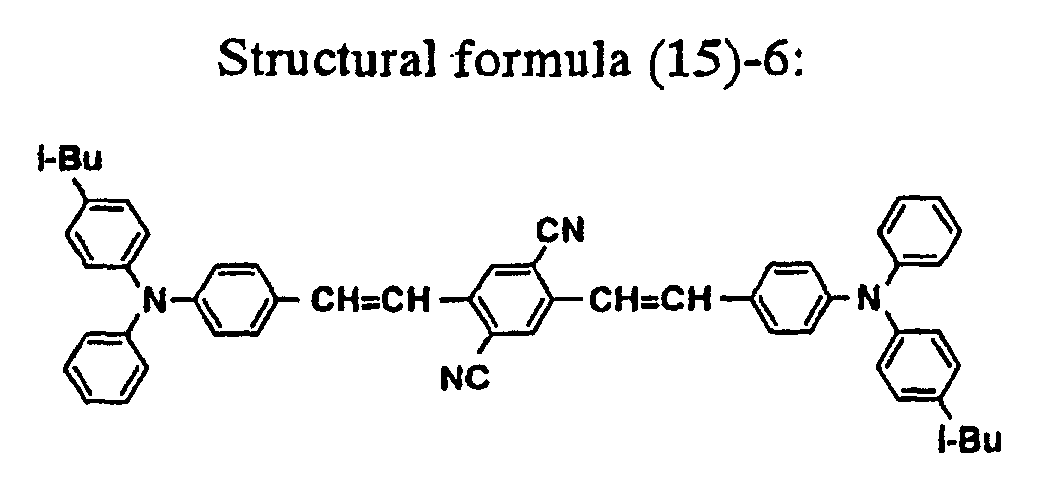
- The organic electroluminescent element was identical with that of Example 2 in layer structure and method of film formation.
- The organic electroluminescent element of Example 8 produced in this manner was examined for luminescent characteristics by applying a forward bias dc voltage in a nitrogen atmosphere. It emitted orange light. By spectral analysis in the same way as in Example 1, the emitted light was found to have the luminescent peak at about 585 nm. In addition, the emitted light was found to have a luminance of 500 cd/m2 at 8V according to the measurements of luminance at various voltages.
- The organic electroluminescent element was allowed to stand for one month in a nitrogen atmosphere after it. had been produced. It remained intact without any sign of deterioration. For accelerated deterioration, the element with an initial luminance of 200 cd/m2 was allowed to emit light continuously by application of constant current.. It took 200 hours for the element to decrease in luminance by half.
- This example demonstrates the production of an organic electroluminescent element of single hetero structure in which the luminescent layer capable of electron transfer is made of a mixture of an aminostyryl compound represented by the following structural formula (15)-7 and Alq3. The former is one of the aminostyryl compounds represented by the above-mentioned general formula [I].

- The organic electroluminescent element was identical with that of Example 2 in layer structure and method of film formation.
- The organic electroluminescent element of Example 9 produced in this manner was examined for luminescent characteristics by applying a forward bias dc voltage in a nitrogen atmosphere. It emitted red light. By spectral analysis in the same way as in Example 1, the emitted light was found to have the luminescent peak at about 615 nm. In addition, the emitted light was found to have a luminance of 580 cd/m2 at 8V according to the measurements of luminance at: various voltages.
- The organic electroluminescent element was allowed to stand for one month in a nitrogen atmosphere after it had been produced. It remained intact without any sign of deterioration. For accelerated deterioration, the element with an initial luminance of 200 cd/m2 was allowed to emit light continuously by application of constant current. It took 300 hours for the element to decrease in luminance by half.
- This example demonstrates the production of an organic electroluminescent element of single hetero structure in which the luminescent layer capable of electron transfer is made of a mixture of an aminostyryl compound represented by the following structural formula (15)-8 and Alq3. The former is one of the aminostyryl compounds represented by the above-mentioned general. formula [I].

- The organic electroluminescent element was identical with that of Example 2 in layer structure and method of film formation.
- The organic electroluminescent element of Example 10 produced in this manner was examined for luminescent characteristics by applying a forward bias dc voltage in a nitrogen atmosphere. It emitted red light. By spectral analysis in the same way as in Example 1, the emitted light was found to have the luminescent peak at about 610 nm. In addition, the emitted light was found to have a luminance of 430 cd/m2 at 8V according to the measurements of luminance at various voltages.
- The organic electroluminescent element was allowed to stand for one month in a nitrogen atmosphere after it had been produced. It remained intact without any sign of deterioration. For accelerated deterioration, the element with an initial luminance of 200 cd/m2 was allowed to emit light continuously by application of constant current. It took 150 hours for the element to decrease in luminance by half.
- This example demonstrates the production of an organic electroluminescent element of single hetero structure in which the luminescent layer capable of electron transfer is made of a mixture of an aminostyryl compound represented by the following structural formula (15)-9 and Alq3. The former is one of the aminostyryl compounds represented by the above-mentioned general formula [I].

- The organic electroluminescent element was identical with that of Example 2 in layer structure and method of film formation.
- The organic electroluminescent element of Example 11 produced in this manner was examined for luminescent characteristics by applying a forward bias dc voltage in a nitrogen atmosphere. It emitted red light. By spectral analysis in the same way as in Example 1, the emitted light was found to have the luminescent peak at about 640 nm. In addition, the emitted light was found to have a luminance of 800 cd/m2 at 8V according to the measurements of luminance at various voltages.
- The organic electroluminescent element was allowed to stand for one month in a nitrogen atmosphere after it had been produced. It remained intact without any sign of deterioration. For accelerated deterioration, the element with an initial luminance of 200 cd/m2 was allowed to emit light continuously by application of constant current. It took 450 hours for the element to decrease in luminance by half.
- This example demonstrates the production of an organic electroluminescent element of single hetero structure in which the luminescent layer capable of electron transfer is made of a mixture of an aminostyryl compound represented by the following structural formula (15)-11 and Alq3. The former is one of the aminostyryl compounds represented by the above-mentioned general formula [I].

- The organic electroluminescent element was identical with that of Example 2 in layer structure and method of film formation.
- The organic electroluminescent element of Example 12 produced in this manner was examined for luminescent characteristics by applying a forward bias dc voltage in a nitrogen atmosphere. It emitted orange light. By spectral analysis in the same way as in Example 1, the emitted light was found to have the luminescent peak at about 580 nm. In addition, the emitted light was found to have a luminance of 1000 cd/m2 at 8V according to the measurements of luminance at various voltages.
- The organic electroluminescent element was allowed to stand for one month in a nitrogen atmosphere after it had been produced. It remained intact without any sign of deterioration. For accelerated deterioration, the element with an initial luminance of 200 cd/m2 was allowed to emit light continuously by application of consfant current. It took 750 hours for the element to decrease in luminance by half.
- This example demonstrates the production of an organic electroluminescent element of single hetero structure in which the luminescent layer capable of electron transfer is made of a mixture of an aminostyryl compound represented by the following structural formula (15)-12 and Alq3. The former is one of the aminostyryl compounds represented by the above-mentioned general formula [I].

- The organic electroluminescent element was identical with that of Example 2 in layer structure and method of film formation.
- The organic electroluminescent element of Example 13 produced in this manner was examined for luminescent characteristics by applying a forward bias dc voltage in a nitrogen atmosphere. It emitted orange light. By spectral analysis in the same way as in Example 1, the emitted light was found to have the luminescent peak at about 600 nm. In addition, the emitted light was found to have a luminance of 850 cd/m2 at 8V according to the measurements of luminance at various voltages.
- The organic electroluminescent element was allowed to stand for one month in a nitrogen atmosphere after it had been produced. It remained intact without any sign of deterioration. For accelerated deterioration, the element with an initial luminance of 200 cd/m2 was allowed to emit light continuously by application of constant current. It took 600 hours for the element to decrease in luminance by half.
- This example demonstrates the production of an organic electroluminescent element of single hetero structure in which the luminescent layer capable of electron transfer is made of a mixture of an aminostyryl compound represented by the following structural formula (17)-1 and Alq3. The former is one of the aminostyryl compounds represented by the above-mentioned general formula [I].

- The organic electroluminescent element was identical with that of Example 2 in layer structure and method of film formation.
- The organic electroluminescent element of Example 14 produced in this manner was examined for luminescent characteristics by applying a forward bias dc voltage in a nitrogen atmosphere. It emitted red light. By spectral analysis in the same way as in Example 1, the emitted light was found to have the luminescent peak at about 620 nm. In addition, the emitted light was found to have a luminance of 1500 cd/m2 at 8V according to the measurements of luminance at various voltages.
- The organic electroluminescent element was allowed to stand for one month in a nitrogen atmosphere after it had been produced. It remained intact without any sign of deterioration. For accelerated deterioration, the element with an initial luminance of 200 cd/m2 was allowed to emit light continuously by application of constant current. It took 800 hours for the element to decrease in luminance by half.
- This example demonstrates the production of an organic electroluminescent element of single hetero structure in which the luminescent layer capable of electron transfer is made of a mixture of an aminostyryl compound represented by the following structural formula (17)-2 and Alq3. The former is one of the aminostyryl compounds represented by the above-mentioned general formula [I].

- The organic electroluminescent element was identical with that of Example 2 in layer structure and method of film formation.
- The organic electroluminescent element of Example 15 produced in this manner was examined for luminescent characteristics by applying a forward bias dc voltage in a nitrogen atmosphere. It emitted red light. By spectral analysis in the same way as in Example 1, the emitted light was found to have the luminescent peak at about 645 nm. In addition, the emitted light was found to have a luminance of 1200 cd/m2 at 8V according to the measurements of luminance at various voltages.
- The organic electroluminescent element was allowed to stand for one month in a nitrogen atmosphere after it had been produced. It remained intact without any sign of deterioration. For accelerated deterioration, the element with an initial luminance of 200 cd/m2 was allowed to emit light continuously by application of constant current. It took 700 hours for the element to decrease in luminance by half.
- This example demonstrates the production of an organic electroluminescent element of single hetero structure in which the luminescent layer capable of electron transfer is made of a mixture of an aminostyryl compound represented by the following structural formula (17)-3 and Alq3. The former is one of the aminostyryl compounds represented by the above-mentioned general formula [I].

- The organic electroluminescent element was identical with that of Example 2 in layer structure and method of film formation.
- The organic electroluminescent element produced in this manner was examined for luminescent characteristics by applying a forward bias dc voltage in a nitrogen atmosphere. It emitted red light. By spectral analysis in the same way as in Example 1, the emitted light was found to have the luminescent peak at about 590 nm. In addition, the emitted light was found to have a luminance of 780 cd/m2 at 8V according to the measurements of luminance at various voltages.
- The organic electroluminescent element was allowed to stand for one month in a nitrogen atmosphere after it had been produced. It remained intact without any sign of deterioration. For accelerated deterioration, the element with an initial luminance of 200 cd/m2 was allowed to emit light continuously by application of constant current. It took 500 hours for the element to decrease in luminance by half.
- This example demonstrates the production of an organic electroluminescent element of single hetero structure in which the luminescent layer capable of electron transfer is made of a mixture of an aminostyryl compound represented by the following structural formula (17)-4 and Alq3. The former is one of the aminostyryl compounds represented by the above-mentioned general formula [I].

- The organic electroluminescent element was identical with that of Example 2 in layer structure and method of film formation.
- The organic electroluminescent element of Example 17 produced in this manner was. examined for luminescent characteristics by applying a forward bias dc voltage in a nitrogen atmosphere. It emitted red light. By spectral analysis in the same way as in Example 1, the emitted light was found to have the luminescent peak at about 620 nm. In addition, the emitted light was found to have a luminance of 1100 cd/m2 at 8V according to the measurements of luminance at various voltages.
- The organic electroluminescent element was allowed to stand for one month in a nitrogen atmosphere after it had been produced. It remained intact without any sign of deterioration. For accelerated deterioration, the element with an initial luminance of 200 cd/m2 was allowed to emit light continuously by application of constant current. It took 600 hours for the element to decrease in luminance by half.
- This example demonstrates the production of an organic electroluminescent element of single hetero structure in which the luminescent layer capable of electron transfer is made of a mixture of an aminostyryl compound represented by the following structural formula (17)-5 and Alq3. The former is one of the aminostyryl compounds represented by the above-mentioned general formula [I].

- The organic electroluminescent element was identical with that of Example 2 in layer structure and method of film formation.
- The organic electroluminescent element of Example 18 produced in this manner was examined for luminescent characteristics by applying a forward bias dc voltage in a nitrogen atmosphere. It emitted red light. By spectral analysis in the same way as in Example 1, the emitted light was found to have the luminescent peak at about 650 nm. In addition, the emitted light was found to have a luminance of 700 cd/m2 at 8V according to the measurements of luminance at various voltages.
- The organic electroluminescent element was allowed to stand for one month in a nitrogen atmosphere after it had been produced. It remained intact without any sign of deterioration. For accelerated deterioration, the element with an initial luminance of 200 cd/m2 was allowed to emit light continuously by application of constant current. It took 400 hours for the element to decrease in luminance by half.
- This example demonstrates the production of an organic electroluminescent element of single hetero structure in which the luminescent layer capable of electron transfer is made of a mixture of an aminostyryl compound represented by the following structural formula (15)-5 and Alq3. The former is one of the aminostyryl compounds represented by the above-mentioned general formula [I].

- The organic electroluminescent element was identical with that of Example 2 in layer structure and method of film formation.
- The organic electroluminescent element of Example produced in this manner was examined for luminescent characteristics by applying a forward bias dc voltage in a nitrogen atmosphere. It emitted red light. By spectral analysis in the same way as in Example 1, the emitted light was found to have the luminescent peak at about 655 nm. In addition, the emitted light was found to have a luminance of 1500 cd/m2 at 8V according to the measurements of luminance at various voltages.
- The organic. electroluminescent element was allowed to stand for one month in a nitrogen atmosphere after it had been produced. It remained intact without any sign of deterioration. For accelerated deterioration, the element with an initial luminance of 200 cd/m2 was allowed to emit light continuously by application of constant current. It took 700 hours for the element to decrease in luminance by half.
- This example demonstrates the production of an organic electroluminescent element of single hetero structure in which the luminescent layer capable of hole transfer is made of a mixture of an aminostyryl compound represented by the above-mentioned structural formula (15)-3 and a-NPD, and the luminescent layer capable of electron transfer is made of a mixture of an aminostyryl compound represented by the above-mentioned structural formula (15)-3 and Alq3. The former is one of the aminostyryl compounds represented by the above-mentioned general formula [I].
- First, the process was started by setting in a vacuum vapor deposition apparatus a glass substrate (30 × 30 mm) having a 100-nm thick anode of ITO formed on one side thereof. The substrate was covered with a metal mask having a plurality of unit openings each measuring 2.0 × 2.0 mm. On the substrate were deposited by vacuum deposition (at 10-4 Pa or less) the aminostyryl compound of the above-mentioned structural formula (15)-3 and a-NPD (as the hole transfer material). There was formed a 50-nm thick hole transfer layer (functioning also as a luminescent layer) consisting of the two components in a ratio of 1:1 by weight. The rate of deposition was 0.1 nm/sec.
- Then, on the hole transfer layer (functioning also as a luminescent layer) were deposited by vacuum deposition the aminostyryl compound of the above-mentioned structural formula (15)-3 and Alq3 (as the electron transfer material). There was formed a 50-nm thick electron transfer layer (functioning also as a luminescent layer) consisting of the two components in a ratio of 1:1 by weight. The rate of deposition was 0.1 nm/sec.
- The cathode (in laminate structure) was formed from Mg and Ag by vacuum deposition. The Mg film was 50 nm thick and the Ag film was 150 nm thick. The rate of deposition was 1 nm/sec. Thus there was obtained the organic electroluminescent element of Example 20 as shown Fig. 3.
- The organic electroluminescent element of Example 20 produced in this manner was examined for luminescent characteristics by applying a forward bias dc voltage in a nitrogen atmosphere. It emitted red light. By spectral analysis with a spectroscope having a photodiode array as a detector (made by Otsuka Electronics Co., Ltd.), the emitted light was found to have the luminescent peak at about 635 nm. In addition, the emitted light was found to have a luminance of 1800 cd/m2 at 8V according to the measurements of luminance at various voltages.
- The organic electroluminescent element was allowed to stand for one month in a nitrogen atmosphere after it had been produced. It remained intact without any sign of deterioration. For accelerated deterioration, the element with an initial luminance of 200 cd/m2 was allowed to emit light continuously by application of constant current. It took 1000 hours for the element to decrease in luminance by half.
- This example demonstrates the production of an organic electroluminescent element in which the luminescent layer capable of hole transfer is made of a mixture of an aminostyryl compound represented by the above-mentioned structural formula (15)-3 and a-NPD (a-naphthylphenyldiamine). The former is one of the aminostyryl compounds represented by the above-mentioned general formula [I].
- First, the process was started by setting in a vacuum vapor deposition apparatus a glass substrate (30 × 30 mm) having a 100-nm thick anode of ITO formed on one side thereof. The substrate was covered with a metal mask having a plurality of unit openings each measuring 2.0 × 2.0 mm. On the substrate were deposited by vacuum deposition (at 10-4 Pa or less) the aminostyryl compound of the above-mentioned structural formula (15)-3 and a-NPD (as the hole transfer material). There was formed a 50-nm thick hole transfer layer (functioning also as a luminescent layer) consisting of the two components in a ratio of 1:1 by weight. The rate of deposition was 0.1 nm/sec.
- Then, on the hole transfer layer (functioning also as a luminescent layer) was deposited by vacuum deposition vasocuproin of the following structural formula. There was formed a 15-nm thick hole blocking layer. The rate of deposition was 0.1 nm/sec.

- Then, on the hole blocking layer was deposited Alq3 (tris(8-quinolinol)aluminum) of the above-mentioned structural formula. There was formed a 50-nm thick electron transfer layer. The rate of deposition was 0.2 nm/sec.
- The cathode (in laminate structure) was formed from Mg and Ag by vacuum deposition. The Mg film was 50 nm thick and the Ag film was 150 nm thick. The rate of deposition was 1 nm/sec. Thus there was obtained the organic electroluminescent element of Example 21 as shown Fig. 7.
- The organic electroluminescent element of Example 21 produced in this manner was examined for luminescent characteristics by applying a forward bias dc voltage in a nitrogen atmosphere. It emitted red light. By spectral analysis with a spectroscope having a photodiode array as a detector (made by Otsuka Electronics Co., Ltd.), the emitted light was found to have the luminescent peak at about 630 nm. In addition, the emitted light was found to have a luminance of 2500 cd/m2 at 8V according to the measurements of luminance at various voltages.
- The organic electroluminescent element was allowed to stand for one month in a nitrogen atmosphere after it had been produced. It remained intact without any sign of deterioration. For accelerated deterioration, the element with an initial luminance of 200 cd/m2 was allowed to emit light continuously by application of constant current. It took 1000 hours for the element to decrease in luminance by half.
- This example demonstrates the production of an organic electroluminescent element in which the luminescent layer capable of electron transfer is made of a mixture of an aminostyryl compound represented by the above-mentioned structural formula (15)-3 and Alq3. The former is one of the aminostyryl compounds represented by the above-mentioned general formula [I].
- First, the process was started by setting in a vacuum vapor deposition apparatus a glass substrate (30 × 30 mm) having a 100-nm thick anode of ITO formed on one side thereof. The substrate was covered with a metal mask having a plurality of unit openings each measuring 2.0 × 2.0 mm. On the substrate was deposited by vacuum deposition (at 10-4 Pa or less) a-NPD by the under-mentioned structural formula to form a 30-nm thick film. The rate of deposition was 0.1 nm/sec.
- Then, on the hole transfer layer was co-deposited by vacuum deposition a 1:1 mixture (by weight) of the compound of the above-mentioned structural formula (15)-3 and Alq3 as the electron transfer material. There was formed a 30-nm thick electron transfer layer (functioning also as a luminescent layer) composed of the above-mentioned two components. The rate of deposition was 0.2 nm/sec.
- Then, on the hole transfer layer (functioning also as a luminescent layer) was deposited by vacuum deposition vasocuproin of the above-mentioned structural formula. There was formed a 15-nm thick hole blocking layer. The rate of deposition was 0.1 nm/sec.
- Then, on the hole blocking layer was deposited Alq3 of the above-mentioned structural formula as the electron transfer layer material. There was formed a 30-nm thick electron transfer layer. The rate of deposition was 0.2 nm/sec.
- The cathode (in laminate structure) was formed from Mg and Ag by vacuum deposition. The Mg film was 50 nm thick and the Ag film was 150 nm thick. The rate of deposition was 1 nm/sec. Thus there was obtained the organic electroluminescent element as shown Fig. 9.
- The organic electroluminescent element of Example 22 produced in this manner was examined for luminescent characteristics by applying a forward bias dc voltage in a nitrogen atmosphere. It emitted red light. By spectral analysis in the same way as in Example 21, the emitted light was found to have the luminescent peak at about 630 nm. In addition, the emitted light was found to have a luminance of 3400 cd/m2 at 8V according to the measurements of luminance at various voltages.
- The organic electroluminescent element was allowed to stand for one month in a nitrogen atmosphere after it had been produced. It remained intact without any sign of deterioration. For accelerated deterioration, the element with an initial luminance of 200 cd/m2 was allowed to emit light continuously by application of constant current. It took 1200 hours for the element to decrease in luminance by half.
- This example demonstrates the production of an organic electroluminescent element in which the luminescent layer is made of a mixture of an aminostyryl compound represented by the above-mentioned structural formula (15)-3 and an aminostyryl compound represented by the above-mentioned structural formula (15)-1.
- First, the process was started by setting in a vacuum vapor deposition apparatus a glass substrate (30 × 30 mm) having a 100-nm thick anode of ITO formed on one side thereof. The substrate was covered with a metal mask having a plurality of unit openings each measuring 2.0 × 2.0 mm. On the substrate was deposited by vacuum deposition (at 10-4 Pa or less) a-NPD to form a 30-nm thick film. The rate of deposition was 0.2 nm/sec.
- Then, on the hole transfer layer was co-deposited by vacuum deposition a 1:3 mixture (by weight) of the compound of the above-mentioned structural formula (15)-3 and the compound of the above-mentioned structural formula (15)-1 as the luminescent material. There was formed a 30-nm thick luminescent layer composed of the above-mentioned two compounds. The rate of deposition was 0.1 nm/sec for the former compound and 0.3 nm/sec for the latter compound.
- Then, on the luminescent layer was deposited by vacuum deposition vasocuproin of the above-mentioned structural formula as the hole blocking layer material. There was formed a 15-nm thick hole blocking layer. The rate of deposition was 0.1 nm/sec.
- Then, on the hole blocking layer was deposited Alq3 of the above-mentioned structural formula as the electron transfer material. There was formed a 30-nm thick electron transfer layer. The rate of deposition was 0.2 nm/sec.
- The cathode (in laminate structure) was formed from Mg and Ag by vacuum deposition. The Mg film was 50 nm thick and the Ag film was 150 nm thick. The rate of deposition was 1 nm/sec. Thus there was obtained the organic electroluminescent element of Example 23 as shown Fig. 9.
- The organic electroluminescent element of Example 23 produced in this manner was examined for luminescent characteristics by applying a forward bias dc voltage in a nitrogen atmosphere. It emitted red light. By spectral analysis in the same way as in Example 21, the emitted light was found to have the luminescent peak at about 640 nm. In addition, the emitted light was found to have a luminance of 4000 cd/m2 at 8V according to the measurements of luminance at various voltages.
- The organic electroluminescent element was allowed to stand for one month in a nitrogen atmosphere after it had been produced. It remained intact without any sign of deterioration. For accelerated deterioration, the element with an initial luminance of 200 cd/m2 was allowed to emit light continuously by application of constant current. It took 1600 hours for the element to decrease in luminance by half.
- This example demonstrates the production of an organic electroluminescent element in which the electron transfer layer is made of a mixture of an aminostyryl compound of the above-mentioned structural formula (15)-3 and DCM of the above-mentioned structural formula. The former is one of the aminostyryl compounds represented by the above-mentioned general formula [I].
- First, the process was started by setting in a vacuum vapor deposition apparatus a glass substrate (30 × 30 mm) having a 100-nm thick anode of ITO formed on one side thereof. The substrate was covered with a metal mask having a plurality of unit openings each measuring 2.0 × 2.0 mm. On the substrate was deposited by vacuum deposition (at 10-4 Pa or less) a-NPD to form a 30-nm thick film. The rate of deposition was 0.1 nm/sec.
- Then, on the hole transfer layer was co-deposited by vacuum deposition a 10:1 mixture (by weight) of the compound of the above-mentioned structural formula (15)-3 and the above-mentioned DCM. There was formed a 30-nm thick electron transfer layer (functioning also as a luminescent layer) composed of the above-mentioned two compounds. The rate of deposition was 0.5 nm/sec for the former compound and 0.05 nm/sec for the latter compound.
- Then, on the luminescent layer was deposited by vacuum deposition vasocuproin of the above-mentioned structural formula as the hole blocking layer material. There was formed a 15-nm thick hole blocking layer. The rate of deposition was 0.1 nm/sec.
- Then, on the hole blocking layer was deposited Alq3 of the above-mentioned structural formula as the electron transfer material. There was formed a 30-nm thick electron transfer layer. The rate of deposition was 0.2 nm/sec.
- The cathode (in laminate structure) was formed from Mg and Ag by vacuum deposition. The Mg film was 50 nm thick and the Ag film was 150 nm thick. The rate of deposition was 1 nm/sec. Thus there was obtained the organic electroluminescent element as shown Fig. 9.
- The organic electroluminescent element of Example 24 produced in this manner was examined for luminescent characteristics by applying a forward bias dc voltage in a nitrogen atmosphere. It emitted red light. By spectral analysis in the same way as in Example 21, the emitted light was found to have the luminescent peak at about 630 nm. In addition, the emitted light was found to have a luminance of 1000 cd/m2 at 8V according to the measurements of luminance at various voltages.
- The organic electroluminescent element was allowed to stand for one month in a nitrogen atmosphere after it had been produced. It remained intact without any sign of deterioration. For accelerated deterioration, the element with an initial luminance of 200 cd/m2 was allowed to emit light continuously by application of constant current. It took 600 hours for the element to decrease in luminance by half.
- This example demonstrates the production of an organic electroluminescent element in which the electron transfer layer is made of a mixture of an aminostyryl compound of the above-mentioned structural formula (15)-2 and Alq3. The former is one of the aminostyryl compounds represented by the above-mentioned general formula [I].
- The organic electroluminescent element was identical with that of Example 22 in layer structure and method of film formation.
- The organic electroluminescent element of Example 25 produced in this manner was examined for luminescent characteristics by applying a forward bias dc voltage in a nitrogen atmosphere. It emitted orange light. By spectral analysis in the same way as in Example 21, the emitted light was found to have the luminescent peak at about 590 nm. In addition, the emitted light was found to have a luminance of 1100 cd/m2 at 8V according to the measurements of luminance at various voltages.
- The organic electroluminescent element was allowed to stand for one month in a nitrogen atmosphere after it had been produced. It remained intact without any sign of deterioration. For accelerated deterioration, the element with an initial luminance of 200 cd/m2 was allowed to emit light continuously by application of constant current. It took 700 hours for the element to decrease in luminance by half.
- This example demonstrates the production of an organic electroluminescent element in which the electron transfer layer is made of a mixture of an aminostyryl compound of the above-mentioned structural formula (15)-4 and Alq3. The former is one of the aminostyryl compounds represented by the above-mentioned general formula [I].
- The organic electroluminescent element was identical with that of Example 22 in layer structure and method of film formation.
- The organic electroluminescent element of Example 26 produced in this manner was examined for luminescent characteristics by applying a forward bias dc voltage in a nitrogen atmosphere. It emitted red light. By spectral analysis in the same way as in Example 21, the emitted light was found to have the luminescent peak at about 610 nm. In addition, the emitted light was found to have a luminance of 1000 cd/m2 at 8V according to the measurements of luminance at various voltages.
- The organic electroluminescent element was allowed to stand for one month in a nitrogen atmosphere after it had been produced. It remained intact without any sign of deterioration. For accelerated deterioration, the element with an initial luminance of 200 cd/m2 was allowed to emit light continuously by application of constant current. It took 550 hours for the element to decrease in luminance by half.
- This example demonstrates the production of an organic electroluminescent element in which the electron transfer layer is made of a mixture of an aminostyryl compound of the above-mentioned structural formula (15)-6 and Alq3. The former is one of the aminostyryl compounds represented by the above-mentioned general formula [I].
- The organic electroluminescent element was identical with that of Example 22 in layer structure and method of film formation.
- The organic electroluminescent element of Example 27 produced in this manner was examined for luminescent characteristics by applying a forward bias dc voltage in a nitrogen atmosphere. It emitted orange light. By spectral analysis in the same way as in Example 21, the emitted light was found to have the luminescent peak at about 585 nm. In addition, the emitted light was found to have a luminance of 600 cd/m2 at 8V according to the measurements of luminance at various voltages.
- The organic electroluminescent element was allowed to stand for one month in a nitrogen atmosphere after it had been produced. It remained intact without any sign of deterioration. For accelerated deterioration, the element with an initial luminance of 200 cd/m2 was allowed to emit light continuously by application of constant current. It took 300 hours for the element to decrease in luminance by half.
- This example demonstrates the production of an organic electroluminescent element in which the electron transfer layer is made of a mixture of an aminostyryl compound of the above-mentioned structural formula (15)-7 and Alq3.
- The organic electroluminescent element was identical with that of Example 22 in layer structure and method of film formation.
- The organic electroluminescent element of Example 28 produced in this manner was examined for luminescent characteristics by applying a forward bias dc voltage in a nitrogen atmosphere. It emitted red light. By spectral analysis in the same way as in Example 21, the emitted light was found to have the luminescent peak at about 615 nm. In addition, the emitted light was found to have a luminance of 650 cd/m2 at 8V according to the measurements of luminance at various voltages.
- The organic electroluminescent element was allowed to stand for one month in a nitrogen atmosphere after it had been produced. It remained intact without any sign of deterioration. For accelerated deterioration, the element with an initial luminance of 200 cd/m2 was allowed to emit light continuously by application of constant current. It took 350 hours for the element to decrease in luminance by half.
- This example demonstrates the production of an organic electroluminescent element in which the electron transfer layer is made of a mixture of an aminostyryl compound of the above-mentioned structural formula (15)-8 and Alq3. The former is one of the aminostyryl compounds represented by the above-mentioned general formula [I].
- The organic electroluminescent element was identical with that of Example 22 in layer structure and method of film formation.
- The organic electroluminescent element of Example 29 produced in this manner was examined for luminescent characteristics by applying a forward bias dc voltage in a nitrogen atmosphere. It emitted red light. By spectral analysis in the same way as in Example 21, the emitted light was found to have the luminescent peak at about 610 nm. In addition, the emitted light was found to have a luminance of 500 cd/m2 at 8V according to the measurements of luminance at various voltages.
- The organic electroluminescent element was allowed to stand for one month in a nitrogen atmosphere after it had been produced. It remained intact without any sign of deterioration. For accelerated deterioration, the element with an initial luminance of 200 cd/m2 was allowed to emit light continuously by application of constant current. It took 200 hours for the element to decrease in luminance by half.
- This example demonstrates the production of an organic electroluminescent element in which the electron transfer layer is made of a mixture of an aminostyryl compound of the above-mentioned structural formula (15)-9 and Alq3. The former is one of the aminostyryl compounds represented by the above-mentioned general formula [I].
- The organic electroluminescent element was identical with that of Example 22 in layer structure and method of film formation.
- The organic electroluminescent element of Example 30 produced in this manner was examined for luminescent characteristics by applying a forward bias dc voltage in a nitrogen atmosphere. It emitted red light. By spectral analysis in the same way as in Example 21, the emitted light was found to have the luminescent peak at about 640 nm. In addition, the emitted light was found to have a luminance of 920 cd/m2 at 8V according to the measurements of luminance at various voltages.
- The organic electroluminescent element was allowed to stand for one month in a nitrogen atmosphere after it had been produced. It remained intact without any sign of deterioration. For accelerated deterioration, the element with an initial luminance of 200 cd/m2 was allowed to emit light continuously by application of constant current. It took 480 hours for the element to decrease in luminance by half.
- This example demonstrates the production of an organic electroluminescent element in which the electron transfer layer is made of a mixture of an aminostyryl compound of the above-mentioned structural formula (15)-11 and Alq3. The former is one of the aminostyryl compounds represented by the above-mentioned general formula [I].
- The organic electroluminescent element was identical with that of Example 22 in layer structure and method of film formation.
- The organic electroluminescent element of Example 31 produced in this manner was examined for luminescent characteristics by applying a forward bias dc voltage in a nitrogen atmosphere. It emitted orange light. By spectral analysis in the same way as in Example 21, the emitted light was found to have the luminescent peak at about 580 nm. In addition, the emitted light was found to have a luminance of 1100 cd/m2 at 8V according to the measurements of luminance at various voltages.
- The organic electroluminescent element was allowed to stand for one month in a nitrogen atmosphere after it had been produced. It remained intact without any sign of deterioration. For accelerated deterioration, the element with an initial luminance of 200 cd/m2 was allowed to emit light continuously by application of constant current. It took 800 hours for the element to decrease in luminance by half.
- This example demonstrates the production of an organic electroluminescent element in which the electron transfer layer is made of a mixture of an aminostyryl compound of the above-mentioned structural formula (15)-12 and Alq3. The former is one of the aminostyryl compounds represented by the above-mentioned general formula [I].
- The organic electroluminescent element was identical with that of Example 22 in layer structure and method of film formation.
- The organic electroluminescent element of Example 32 produced in this manner was examined for luminescent characteristics by applying a forward bias dc voltage in a nitrogen atmosphere. It emitted orange light. By spectral analysis in the same way as in Example 21, the emitted light was found to have the luminescent peak at about 600 nm. In addition, the emitted light was found to have a luminance of 900 cd/m2 at 8V according to the measurements of luminance at various voltages.
- The organic electroluminescent element was allowed to stand for one month in a nitrogen atmosphere after it had been produced. It remained intact without any sign of deterioration. For accelerated deterioration, the element with an initial luminance of 200 cd/m2 was allowed to emit light continuously by application of constant current. It took 660 hours for the element to decrease in luminance by half.
- This example demonstrates the production of an organic electroluminescent element in which the electron transfer layer is made of a mixture of an aminostyryl compound of the above-mentioned structural formula (17)-1 and Alq3. The former is one of the aminostyryl compounds represented by the above-mentioned general formula [I].
- The organic electroluminescent element was identical with that of Example 22 in layer structure and method of film formation.
- The organic electroluminescent element of Example 33 produced in this manner was examined for luminescent characteristics by applying a forward bias dc voltage in a nitrogen atmosphere. It emitted red light. By spectral analysis in the same way as in Example 21, the emitted light was found to have the luminescent peak at about 620 nm. In addition, the emitted light was found to have a luminance of 1650 cd/m2 at 8V according to the measurements of luminance at various voltages.
- The organic electroluminescent element was allowed to stand for one month in a nitrogen atmosphere after it had been produced. It remained intact without any sign of deterioration. For accelerated deterioration, the element with an initial luminance of 200 cd/m2 was allowed to emit light continuously by application of constant current. It took 880 hours for the element to decrease in luminance by half.
- This example demonstrates the production of an organic electroluminescent element in which the electron transfer layer is made of a mixture of an aminostyryl compound of the above-mentioned structural formula (17)-2 and Alq3. The former is one of the aminostyryl compounds represented by the above-mentioned general formula [I].
- The organic electroluminescent element was identical with that of Example 22 in layer structure and method of film formation.
- The organic electroluminescent element produced in this manner was examined for luminescent characteristics by applying a forward bias dc voltage in a nitrogen atmosphere. It emitted red light. By spectral analysis in the same way as in Example 21, the emitted light was found to have the luminescent peak at about 645 nm. In addition, the emitted light was found to have a luminance of 1300 cd/m2 at 8V according to the measurements of luminance at various voltages.
- The organic electroluminescent element was allowed to stand for one month in a nitrogen atmosphere after it had been produced. It remained intact without any sign of deterioration. For accelerated deterioration, the element with an initial luminance of 200 cd/m2 was allowed to emit light continuously by application of constant current. It took 800 hours for the element to decrease in luminance by half.
- This example demonstrates the production of an organic electroluminescent element in which the electron transfer layer is made of a mixture of an aminostyryl compound of the above-mentioned structural formula (17)-3 and Alq3. The former is one of the aminostyryl compounds represented by the above-mentioned general formula [I].
- The organic electroluminescent element was identical with that of Example 22 in layer structure and method of film formation.
- The organic electroluminescent element produced in this manner was examined for luminescent characteristics by applying a forward bias dc voltage in a nitrogen atmosphere. It emitted red light. By spectral analysis in the same way as in Example 21, the emitted light was found to have the luminescent peak at about 600 nm. In addition, the emitted light was found to have a luminance of 1450 cd/m2 at 8V according to the measurements of luminance at various voltages.
- The organic electroluminescent element was allowed to stand for one month in a nitrogen atmosphere after it had been produced. It remained intact without any sign of deterioration. For accelerated deterioration, the element with an initial luminance of 200 cd/m2 was allowed to emit light continuously by application of constant current. It took 700 hours for the element to decrease in luminance by half.
- This example demonstrates the production of an organic electroluminescent element in which the electron transfer layer is made of a mixture of an aminostyryl compound of the above-mentioned structural formula (17)-4 and Alq3. The former is one of the aminostyryl compounds represented by the above-mentioned general formula [I].
- The organic electroluminescent element was identical with that of Example 22 in layer structure and method of film formation.
- The organic electroluminescent element of Example 36 produced in this manner was examined for luminescent characteristics by applying a forward bias dc voltage in a nitrogen atmosphere. It emitted red light. By spectral analysis in the same way as in Example 21, the emitted light was found to have the luminescent peak at about 620 nm. In addition, the emitted light was found to have a luminance of 1200 cd/m2 at 8V according to the measurements of luminance at various voltages.
- The organic electroluminescent element was allowed to stand for one month in a nitrogen atmosphere after it had been produced. It remained intact without any sign of deterioration. For accelerated deterioration, the element with an initial luminance of 200 cd/m2 was allowed to emit light continuously by application of constant current. It took 650 hours for the element to decrease in luminance by half.
- This example demonstrates the production of an organic electroluminescent element in which the electron transfer layer is made of a mixture of an aminostyryl compound of the above-mentioned structural formula (17)-5 and Alq3. The former is one of the aminostyryl compounds represented by the above-mentioned general formula [I].
- The organic electroluminescent element was identical with that of Example 22 in layer structure and method of film formation.
- The organic electroluminescent element of Example 37 produced in this manner was examined for luminescent characteristics by applying a forward bias dc voltage in a nitrogen atmosphere. It emitted red light. By spectral analysis in the same way as in Example 21, the emitted light was found to have the luminescent peak at about 650 nm. In addition, the emitted light was found to have a luminance of 800 cd/m2 at 8V according to the measurements of luminance at various voltages.
- The organic electroluminescent element was allowed to stand for one month in a nitrogen atmosphere after it had been produced. It remained intact without any sign of deterioration. For accelerated deterioration, the element with an initial luminance of 200 cd/m2 was allowed to emit light continuously by application of constant current. It took 500 hours for the element to decrease in luminance by half.
- This example demonstrates the production of an organic electroluminescent element in which the electron transfer layer is made of a mixture of an aminostyryl compound of the above-mentioned structural formula (15)-5 and Alq3.
- The organic electroluminescent element was identical with that of Example 22 in layer structure and method of film formation.
- The organic electroluminescent element of Example 38 produced in this manner was examined for luminescent characteristics by applying a forward bias dc voltage in a nitrogen atmosphere. It emitted red light. By spectral analysis in the same way as in Example 21, the emitted light was found to have the luminescent peak at about 655 nm. In addition, the emitted light was found to have a luminance of 1720 cd/m2 at 8V according to the measurements of luminance at various voltages.
- The organic electroluminescent element was allowed to stand for one month in a nitrogen atmosphere after it had been produced. It remained intact without any sign of deterioration. For accelerated deterioration, the element with an initial luminance of 200 cd/m2 was allowed to emit light continuously by application of constant current. It took 780 hours for the element to decrease in luminance by half.
- This example demonstrates the production of an organic electroluminescent element in which the hole transfer layer is made of a mixture of an aminostyryl compound of the above-mentioned structural formula (15)-3 and a-NPD and the electron transfer layer is made of a mixture of an aminostyryl compound of the above-mentioned structural formula (15)-3 and Alq3. The former is one of the aminostyryl compounds represented by the above-mentioned general formula [I].
- First, the process was started by setting in a vacuum vapor deposition apparatus a glass substrate (30 × 30 mm) having a 100-nm thick anode of ITO formed on one side thereof. The substrate was covered with a metal mask having a plurality of unit openings each measuring 2.0 × 2.0 mm. On the substrate were deposited by vacuum deposition (at 10-4 Pa or less) the compound of the above-mentioned structural formula (15)-3 and a-NPD (as the hole transfer material). There was formed a 30-nm thick hole transfer layer (functioning also as a luminescent layer) consisting of the two components mixed in a ratio of 1:1 by weight. The rate of deposition was 0.1 nm/sec each.
- Then, on the hole transfer layer (functioning also as a luminescent layer) was co-deposited by vacuum deposition a 1:1 mixture (by weight) of the compound of the above-mentioned structural formula (15)-3 and Alq3 (as an electron transfer material). There was formed a 30-nm thick electron transfer layer (functioning also as a luminescent layer) composed of the above-mentioned two compounds. The rate of deposition was 0.2 nm/sec each.
- Then, on the electron transfer layer (functioning also as a luminescent layer) was deposited by vacuum deposition vasocuproin of the above-mentioned structural formula as the hole blocking layer material. There was formed a 15-nm thick hole blocking layer. The rate of deposition was 0.1 nm/sec.
- Then, on the hole blocking layer was deposited Alq3 of the above-mentioned structural formula as the electron transfer material. There was formed a 30-nm thick electron transfer layer. The rate of deposition was 0.2 nm/sec.
- The cathode (in laminate structure) was formed from Mg and Ag by vacuum deposition. The Mg film was 50 nm thick and the Ag film was 150 nm thick. The rate of deposition was 1 nm/sec. Thus there was obtained the organic electroluminescent element of Example 39 as shown Fig. 9.
- The organic electroluminescent element of Example 39 produced in this manner was examined for luminescent characteristics by applying a forward bias dc voltage in a nitrogen atmosphere. It emitted red light. By spectral analysis with a spectroscope having a photodiode array as a detector (made by Otsuka Electronics Co., Ltd.), the emitted light was found to have the luminescent peak at about 635 nm. In addition, the emitted light was found to have a luminance of 2900 cd/m2 at 8V according to the measurements of luminance at various voltages.
- The organic electroluminescent element was allowed to stand for one month in a nitrogen atmosphere after it had been produced. It remained intact without any sign of deterioration. For accelerated deterioration, the element with an initial luminance of 200 cd/m2 was allowed to emit light continuously by application of constant current. It took 1100 hours for the element to decrease in luminance by half.
- This example demonstrates the production of an organic electroluminescent element in which the hole transfer layer is made of an aminostyryl compound of the above-mentioned structural formula (15)-3 in the aminostyryl compounds represented by the above-mentioned general formula [I].
- First, the process was started by setting in a vacuum vapor deposition apparatus a glass substrate (30 × 30 mm) having a 100-nm thick anode of ITO formed on one side thereof. The substrate was covered with a metal mask having a plurality of unit openings each measuring 2.0 × 2.0 mm. On the substrate was deposited by vacuum deposition (at 10-4 Pa or less) the aminostyryl compound of the above-mentioned structural formula (15)-3. There was formed a 50-nm thick hole transfer layer (functioning also as a luminescent layer). The rate of deposition was 0.1 nm/sec each.
- Then, on the hole transfer layer was deposited by vacuum deposition vasocuproin of the above-mentioned structural formula as the hole blocking layer material. There was formed a 15-nm thick hole blocking layer. The rate of deposition was 0.1 nm/sec.
- Then, on the hole blocking layer was deposited Alq3 (tris(8-quinolinol)aluminum) of the above-mentioned structural formula as the electron transfer layer material. There was formed a 50-nm thick electron transfer layer. The rate of deposition was 0.2 nm/sec.
- The cathode (in laminate structure) was formed from Mg and Ag by vacuum deposition. The Mg film was 50 nm thick and the Ag film was 150 nm thick. The rate of deposition was 1 nm/sec. Thus there was obtained the organic electroluminescent element of Example 40 as shown Fig. 7.
- The organic electroluminescent element of Example 40 produced in this manner was examined for luminescent characteristics by applying a forward bias dc voltage in a nitrogen atmosphere. It emitted red light. By spectral analysis with a spectroscope having a photodiode array as a detector (made by Otsuka Electronics Co., Ltd.), the emitted light was found to have the luminescent peak at about 640 nm. In addition, the emitted light was found to have a luminance of 3000 cd/m2 at 8V according to the measurements of luminance at various voltages.
- The organic electroluminescent element was allowed to stand for one month in a nitrogen atmosphere after it had been produced. It remained intact without any sign of deterioration. For accelerated deterioration, the element with an initial luminance of 200 cd/m2 was allowed to emit light continuously by application of constant current. It took 1100 hours for the element to decrease in luminance by half.
- This example demonstrates the production of an organic electroluminescent element in which the luminescent layer capable of electron transfer s made an aminostyryl compound of the above-mentioned structural formula (15)-3 in the aminostyryl compounds represented by the above-mentioned general formula [I].
- First, the process was started by setting in a vacuum vapor deposition apparatus a glass substrate (30 × 30 mm) having a 100-nm thick anode of ITO formed on one side thereof. The substrate was covered with a metal mask having a plurality of unit openings each measuring 2.0 × 2.0 mm. On the substrate was deposited by vacuum deposition (at 10-4 Pa or less) a-NPD of the under-mentioned structural formula. There was formed a 30-nm thick layer. The rate of deposition was 0.1 nm/sec each.
- Then, on the hole transfer layer was deposited by vacuum deposition the compound of the above-mentioned structural formula (15)-3. There was formed a 30-nm thick electron transfer layer (functioning also as a luminescent layer) of the compound of the above-mentioned structural formula (15)-3. The rate of deposition was 0.2 nm/sec.
- Then, on the luminescent blocking layer was deposited vasocuproin of the above-mentioned structural formula as the hole blocking layer material. There was formed a 15-nm thick hole blocking layer. The rate of deposition was 0.1 nm/sec.
- Then, on the hole blocking layer was deposited Alq3 of the above-mentioned structural formula as the electron transfer layer material. There was formed a 30 nm thick electron transfer layer. The rate of deposition was 0.2 nm/sec.
- The cathode (in laminate structure) was formed from Mg and Ag by vacuum deposition. The Mg film was 50 nm thick and the Ag film was 150 nm thick. The rate of deposition was 1 nm/sec. Thus there was obtained the organic electroluminescent element as shown Fig. 9.
- The organic electroluminescent element of Example 41 produced in this manner was examined for luminescent characteristics by applying a forward bias dc voltage in a nitrogen atmosphere. It emitted red light. By spectral analysis in the same way as in Example 40, the emitted light was found to have the luminescent peak at about 640 nm. In addition, the emitted light was found to have a luminance of 3800 cd/m2 at 8V according to the measurements of luminance at various voltages.
- The organic electroluminescent element was allowed to stand for one month in a nitrogen atmosphere after it had been produced. It remained intact without any sign of deterioration. For accelerated deterioration, the element with an initial luminance of 200 cd/m2 was allowed to emit light continuously by application of constant current. It took 1500 hours for the element to decrease in luminance by half.
- This example demonstrates the production of an organic electroluminescent element in which the electron transfer layer is made of an aminostyryl compound of the above-mentioned structural formula (15)-2 in the aminostyryl compounds represented by the above-mentioned general formula [I].
- The organic electroluminescent element was identical with that of Example 41 in layer structure and method of film formation.
- The organic electroluminescent element produced in this manner was examined for luminescent characteristics by applying a forward bias dc voltage in a nitrogen atmosphere. It emitted orange light. By spectral analysis in the same way as in Example 40, the emitted light was found to have the luminescent peak at about 600 nm. In addition, the emitted light was found to have a luminance of 1200 cd/m2 at 8V according to the measurements of luminance at various voltages.
- The organic electroluminescent element was allowed to stand for one month in a nitrogen atmosphere after it had been produced. It remained intact without any sign of deterioration. For accelerated deterioration, the element with an initial luminance of 200 cd/m2 was allowed to emit light continuously by application of constant current. It took 800 hours for the element to decrease in luminance by half.
- This example demonstrates the production of an organic electroluminescent element in which the electron transfer layer is made of an aminostyryl compound of the above-mentioned structural formula (15)-4 in the aminostyryl compounds represented by the above-mentioned general formula [I].
- The organic electroluminescent element was identical with that of Example 41 in layer structure and method of film formation.
- The organic electroluminescent element produced in this manner was examined for luminescent characteristics by applying a forward bias dc voltage in a nitrogen atmosphere. It emitted red light. By spectral analysis in the same way as in Example 40, the emitted light was found to have the luminescent peak at about 620 nm. In addition, the emitted light was found to have a luminance of 1100 cd/m2 at 8V according to the measurements of luminance at various voltages.
- The organic electroluminescent element was allowed to stand for one month in a nitrogen atmosphere after it had been produced. It remained intact without any sign of deterioration. For accelerated deterioration, the element with an initial luminance of 200 cd/m2 was allowed to emit light continuously by application of constant current. It took 600 hours for the element to decrease in luminance by half.
- This example demonstrates the production of an organic electroluminescent element in which the electron transfer layer is made of a compound of the above-mentioned structural formula (15)-6 in the aminostyryl compounds represented by the above-mentioned general formula [I].
- The organic electroluminescent element was identical with that of Example 41 in layer structure and method of film formation.
- The organic electroluminescent element of Example 44 produced in this manner was examined for luminescent characteristics by applying a forward bias dc voltage in a nitrogen atmosphere. It emitted orange light. By spectral analysis in the same way as in Example 40, the emitted light was found to have the luminescent peak at about 595 nm. In addition, the emitted light was found to have a luminance of 700 cd/m2 at 8V according to the measurements of luminance at various voltages.
- The organic electroluminescent element was allowed to stand for one month in a nitrogen atmosphere after it had been produced. It remained intact without any sign of deterioration. For accelerated deterioration, the element with an initial luminance of 200 cd/m2 was allowed to emit light continuously by application of constant current. It took 300 hours for the element to decrease in luminance by half.
- This example demonstrates the production of an organic electroluminescent element in which the electron transfer layer is made of an aminostyryl compound of the above-mentioned structural formula (15)-7 in the aminostyryl compounds represented by the above-mentioned general formula [I].
- The organic electroluminescent element was identical with that of Example 41 in layer structure and method of film formation.
- The organic electroluminescent element of Example 45 produced in this manner was examined for luminescent characteristics by applying a forward bias dc voltage in a nitrogen atmosphere. It emitted orange light. By spectral analysis in the same way as in Example 40, the emitted light was found to have the luminescent peak at about 620 nm. In addition, the emitted light was found to have a luminance of 750 cd/m2 at 8V according to the measurements of luminance at various voltages.
- The organic electroluminescent element was allowed to stand for one month in a nitrogen atmosphere after it had been produced. It remained intact without any sign of deterioration. For accelerated deterioration, the element with an initial luminance of 200 cd/m2 was allowed to emit light continuously by application of constant current. It took 450 hours for the element to decrease in luminance by half.
- This example demonstrates the production of an organic electroluminescent element in which the electron transfer layer is made of an aminostyryl compound of the above-mentioned structural formula (15)-8 in the aminostyryl compounds represented by the above-mentioned general formula [I].
- The organic electroluminescent element was identical with that of Example 41 in layer structure and method of film formation.
- The organic electroluminescent element of Example 46 produced in this manner was examined for luminescent characteristics by applying a forward bias dc voltage in a nitrogen atmosphere. It emitted red light. By spectral analysis in the same way as in Example 40, the emitted light was found to have the luminescent peak at about 620 nm. In addition, the emitted light was found to have a luminance of 520 cd/m2 at 8V according to the measurements of luminance at various voltages.
- The organic electroluminescent element was allowed to stand for one month in a nitrogen atmosphere after it had been produced. It remained intact without any sign of deterioration. For accelerated deterioration, the element with an initial luminance of 200 cd/m2 was allowed to emit light continuously by application of constant current. It took 250 hours for the element to decrease in luminance by half.
- This example demonstrates the production of an organic electroluminescent element in which the electron transfer layer is made of an aminostyryl compound of the above-mentioned structural formula (15)-9 in the aminostyryl compounds represented by the above-mentioned general formula [I].
- The organic electroluminescent element was identical with that of Example 41 in layer structure and method of film formation.
- The organic electroluminescent element of Example 47 produced in this manner was examined for luminescent characteristics by applying a forward bias dc voltage in a nitrogen atmosphere. It emitted red light. By spectral analysis in the same way as in Example 40, the emitted light was found to have the luminescent peak at about 650 nm. In addition, the emitted light was found to have a luminance of 1000 cd/m2 at 8V according to the measurements of luminance at various voltages.
- The organic electroluminescent element was allowed to stand for one month in a nitrogen atmosphere after it had been produced. It remained intact without any sign of deterioration. For accelerated deterioration, the element with an initial luminance of 200 cd/m2 was allowed to emit light continuously by application of constant current. It took 600 hours for the element to decrease in luminance by half.
- This example demonstrates the production of an organic electroluminescent element in which the electron transfer layer is made of an aminostyryl compound of the above-mentioned structural formula (15)-11 in the aminostyryl compounds represented by the above-mentioned general formula [I].
- The organic electroluminescent element was identical with that of Example 41 in layer structure and method of film formation.
- The organic electroluminescent element of Example 48 produced in this manner was examined for luminescent characteristics by applying a forward bias dc voltage in a nitrogen atmosphere. It emitted orange light. By spectral analysis in the same way as in Example 40, the emitted light was found to have the luminescent peak at about 590 nm. In addition, the emitted light was found to have a luminance of 1200 cd/m2 at 8V according to the measurements of luminance at various voltages.
- The organic electroluminescent element was allowed to stand for one month in a nitrogen atmosphere after it had been produced. It remained intact without any sign of deterioration. For accelerated deterioration, the element with an initial luminance of 200 cd/m2 was allowed to emit light continuously by application of constant current. It took 850 hours for the element to decrease in luminance by half.
- This example demonstrates the production of an organic electroluminescent element in which the electron transfer layer is made of an aminostyryl compound of the above-mentioned structural formula (15)-12 in the aminostyryl compounds represented by the above-mentioned general formula [I].
- The organic electroluminescent element was identical with that of Example 41 in layer structure and method of film formation.
- The organic electroluminescent element of Example 49 produced in this manner was examined for luminescent characteristics by applying a forward bias dc voltage in a nitrogen atmosphere. It emitted red light. By spectral analysis in the same way as in Example 40, the emitted light was found to have the luminescent peak at about 610 nm. In addition, the emitted light was found to have a luminance of 930 cd/m2 at 8V according to the measurements of luminance at various voltages.
- The organic electroluminescent element was allowed to stand for one month in a nitrogen atmosphere after it had been produced. It remained intact without any sign of deterioration. For accelerated deterioration, the element with an initial luminance of 200 cd/m2 was allowed to emit light continuously by application of constant current. It took 700 hours for the element to decrease in luminance by half.
- This example demonstrates the production of an organic electroluminescent element in which the electron transfer layer is made of an aminostyryl compound of the above-mentioned structural formula (17)-1 in the aminostyryl compounds represented by the above-mentioned general formula [I].
- The organic electroluminescent element was identical with that of Example 41 in layer structure and method of film formation.
- The organic electroluminescent element produced in this manner was examined for luminescent characteristics by applying a forward bias dc voltage in a nitrogen atmosphere. It emitted red light. By spectral analysis in the same way as in Example 40, the emitted light was found to have the luminescent peak at about 630 nm. In addition, the emitted light was found to have a luminance of 1700 cd/m2 at 8V according to the measurements of luminance at various voltages.
- The organic electroluminescent element was allowed to stand for one month in a nitrogen atmosphere after it had been produced. It remained intact without any sign of deterioration. For accelerated deterioration, the element with an initial luminance of 200 cd/m2 was allowed to emit light continuously by application of constant current. It took 1000 hours for the element to decrease in luminance by half.
- This example demonstrates the production of an organic electroluminescent element in which the electron transfer layer is made of a compound of the above-mentioned structural formula (17)-2 in the aminostyryl compounds represented by the above-mentioned general formula [I].
- The organic electroluminescent element was identical with that of Example 41 in layer structure and method of film formation.
- The organic electroluminescent element of Example 51 produced in this manner was examined for luminescent characteristics by applying a forward bias dc voltage in a nitrogen atmosphere. It emitted orange light. By spectral analysis in the same way as in Example 40, the emitted light was found to have the luminescent peak at about 655 nm. In addition, the emitted light was found to have a luminance of 1400 cd/m2 at 8V according to the measurements of luminance at various voltages.
- The organic electroluminescent element was allowed to stand for one month in a nitrogen atmosphere after it had been produced. It remained intact without any sign of deterioration. For accelerated deterioration, the element with an initial luminance of 200 cd/m2 was allowed to emit light continuously by application of constant current. It took 850 hours for the element to decrease in luminance by half.
- This example demonstrates the production of an organic electroluminescent element in which the electron transfer layer is made of an aminostyryl compound of the above-mentioned structural formula (17)-3.
- The organic electroluminescent element was identical with that of Example 41 in layer structure and method of film formation.
- The organic electroluminescent element of Example 52 produced in this manner was examined for luminescent characteristics by applying a forward bias dc voltage in a nitrogen atmosphere. It emitted red light. By spectral analysis in the same way as in Example 40, the emitted light was found to have the luminescent peak at about 600 nm. In addition, the emitted light was found to have a luminance of 900 cd/m2 at 8V according to the measurements of luminance at various voltages.
- The organic electroluminescent element was allowed to stand for one month in a nitrogen atmosphere after it had been produced. It remained intact without any sign of deterioration.. For accelerated deterioration, the element with an initial luminance of 200 cd/m2 was allowed to emit light continuously by application of constant current. It took 650 hours for the element to decrease in luminance by half.
- This example demonstrates the production of an organic electroluminescent element in which the electron transfer layer is made of a compound of the above-mentioned structural formula (17)-4 in the aminostyryl compounds represented by the above-mentioned general formula [I].
- The organic electroluminescent element was identical with that of Example 41 in layer structure and method of film formation.
- The organic electroluminescent element produced in this manner was examined for luminescent characteristics by applying a forward bias dc voltage in a nitrogen atmosphere. It emitted red light. By spectral analysis in the same way as in Example 40, the emitted light was found to have the luminescent peak at about 630 nm. In addition, the emitted light was found to have a luminance of 1300 cd/m2 at 8V according to the measurements of luminance at various voltages.
- The organic electroluminescent element of Example 53 was allowed to stand for one month in a nitrogen atmosphere after it had been produced. It remained intact without any sign of deterioration. For accelerated deterioration, the element with an initial luminance of 200 cd/m2 was allowed to emit light continuously by application of constant current. It took 750 hours for the element to decrease in luminance by half.
- This example demonstrates the production of an organic electroluminescent element in which the electron transfer layer is made of a compound of the above-mentioned structural formula (17)-5 in the aminostyryl compounds represented by the above-mentioned general formula [I].
- The organic electroluminescent element was identical with that of Example 41 in layer structure and method of film formation.
- The organic electroluminescent element of Example 54 produced in this manner was examined for luminescent characteristics by applying a forward bias dc voltage in a nitrogen atmosphere. It emitted red light. By spectral analysis in the same way as in Example 40, the emitted light was found to have the luminescent peak at about 660 nm. In addition, the emitted light was found to have a luminance of 800 cd/m2 at 8V according to the measurements of luminance at various voltages.
- The organic electroluminescent element was allowed to stand for one month in a nitrogen atmosphere after it had been produced. It remained intact without any sign of deterioration. For accelerated deterioration, the element with an initial luminance of 200 cd/m2 was allowed to emit light continuously by application of constant current. It took 500 hours for the element to decrease in luminance by half.
- This example demonstrates the production of an organic electroluminescent element in which the electron transfer layer is made of an aminostyryl compound of the above-mentioned structural formula (15)-5 in the aminostyryl compounds represented by the above-mentioned general formula [I].
- The organic electroluminescent element was identical with that of Example 41 in layer structure and method of film formation.
- The organic electroluminescent element of Example 55 produced in this manner was examined for luminescent characteristics by applying a forward bias dc voltage in a nitrogen atmosphere. It emitted red light. By spectral analysis in the same way as in Example 40, the emitted light was found to have the luminescent peak at about 660 nm. In addition, the emitted light was found to have a luminance of 1700 cd/m2 at 8V according to the measurements of luminance at various voltages.
- The organic electroluminescent element was allowed to stand for one month in a nitrogen atmosphere after it had been produced. It remained intact without any sign of deterioration. For accelerated deterioration, the element with an initial luminance of 200 cd/m2 was allowed to emit light continuously by application of constant current. It took 900 hours for the element to decrease in luminance by half.
- The organic electroluminescent element of the present invention is constructed such that an organic layer having a luminescent region is arranged between an anode and a cathode. The organic layer is composed of more than one layer, and at least one layer contains at least one species of aminostyryl compounds represented by the above-mentioned general formula [I] alone or in the form of a mixture. Therefore, the luminescent region can be formed from such a specific aminostyryl compound and/or a material capable of efficient energy transmission to it. Thus, the organic electroluminescent element has high fluorescence yields and good thermal stability, and emits red light with high color purity, high luminance, and high reliability.
- In addition, the organic electroluminescent element has a hole blocking layer as mentioned above. This hole blocking layer promotes recombination of holes and electrons in the luminescent layer, although the organic electroluminescent element containing the above-mentioned aminostyryl compound inherently has high quantum yields. Thus the organic electroluminescent element emits light with high luminance and high efficiency.
Claims (55)
- An organic electroluminescent element in which an organic layer having a luminescent region is arranged between an anode and a cathode, characterized in that said organic layer is constructed of at least one layer formed from a mixture containing at least one species of the aminostyryl compounds represented by the following general formula [I].
Y1-CH=CH-X1-CH=CH-Y2 (where, in the general formulas (1) to (3) above, at least one of R1 to R4 is a group selected from halogen atoms, nitro groups, cyano groups, and fluoroalkyl groups, and others are groups selected from hydrogen atom, alkyl groups, aryl groups, alkoxyl groups, halogen atoms, nitro groups, cyano groups, and fluoroalkyl groups, which are identical or different; in the general formulas (4) to (7), at least one of R5 to R10 is a group selected from halogen atoms, nitro groups, cyano groups, and fluoroalkyl groups, and others are groups selected from hydrogen atom, alkyl groups, aryl groups, alkoxyl groups, halogen atoms, nitro groups, cyano groups, and fluoroalkyl groups, which are identical or different.)
Y1 is a group represented by the following general formula (8) or (9), and Y2 is a group represented by the following general formula (8), (9), or (10).(where, in the general formulas (8) to (10) above, R11 and R12 each is a group selected from a hydrogen atom, alkyl groups with optional substituents, and aryl groups with optional substituents, which are identical or different; and R13 to R35 each is a group selected from a hydrogen atom, alkyl groups with optional substituents, and aryl groups with optional substituents, alkoxyl groups with optional substituents, halogen atoms, nitro groups, cyano groups, and fluoroalkyl groups, which are identical or different.)
- The organic electroluminescent element as defined in Claim 1, wherein the general formula [I] is characterized in that X1 is a group represented by any one of the following structural formulas (11) to (14)and Y1 and Y2 each is a group represented by the following general formula (8) or (9).
 (where, in the general formulas (8) and (9) above, R11 and R12 are defined as above, R13 to R30 are defined as above (or a trifluoromethyl group if defined as fluoroalkyl groups).
- The organic electroluminescent element as defined in Claim 1, wherein the organic layer is of organic multilayer structure composed of a hole transfer layer and an electron transfer layer, with at least the electron transfer layer in the organic multilayer structure being a layer of a mixture containing at least one species of the aminostyryl compounds represented by the general formula [I] above.
- The organic electroluminescent element as defined in Claim 1, wherein the organic layer is of organic multilayer structure composed of a hole transfer layer and an electron transfer layer, with at least the hole transfer layer in the organic multilayer structure being a layer of a mixture containing at least one species of the aminostyryl compounds represented by the general formula [I] above.
- The organic electroluminescent element as defined in Claim 1, wherein the organic layer is of organic multilayer structure composed of a hole transfer layer and an electron transfer layer, with the hole transfer layer being a layer of a mixture containing at least one species of the aminostyryl compounds represented by the general formula [I] above, and the electron transfer layer being a layer of a mixture containing at least one species of the aminostyryl compounds represented by the general formula [I] above.
- The organic electroluminescent element as defined in Claim 1, wherein the organic layer is of organic multilayer structure composed of a hole transfer layer, a luminescent layer, and an electron transfer layer, with at least the luminescent layer in the organic multilayer structure being a layer of a mixture containing at least one species of the aminostyryl compounds represented by the general formula [I] above.
- A luminescent device in which is used the organic electroluminescent element as defined in any of Claims 1 to 6.
- The luminescent device as defined in Claim 7, which is constructed for use as a display device.
- An organic electroluminescent element in which an organic layer having a luminescent region is arranged between an anode and a cathode, characterized in that said organic layer is constructed of at least one layer formed from a mixture containing at least one species of the aminostyryl compounds represented by the following structural formulas (15)-1 to (15)-12, (16)-1 to (16)-12, (17)-1 to (17)-6, and (18)-1 to (18)-6.


- The organic electroluminescent element as defined in Claim 9, wherein the organic layer is of organic multilayer structure composed of a hole transfer layer and an electron transfer layer, with at least the electron transfer layer in the organic multilayer structure being a layer of a mixture containing at least one species said aminostyryl compounds.
- The organic electroluminescent element as defined in Claim 9, wherein the organic layer is of organic multilayer structure composed of a hole transfer layer and an electron transfer layer, with at least the hole transfer layer in the organic multilayer structure being a layer of a mixture containing at least one species of said aminostyryl compounds.
- The organic electroluminescent element as defined in Claim 9, wherein the organic layer is of organic multilayer structure composed of a hole transfer layer and an electron transfer layer, with the hole transfer layer being a layer of a mixture containing at least one species of the aminostyryl compounds mentioned above, and the electron transfer layer being a layer of a mixture containing at least one species of said aminostyryl compounds.
- The organic electroluminescent element as defined in Claim 9, wherein the organic layer is of organic multilayer structure composed of a hole transfer layer, a luminescent layer, and an electron transfer layer, with at least the luminescent layer in the organic multilayer structure being a layer of a mixture containing at least one species of said aminostyryl compounds.
- The organic electroluminescent element as defined in Claim 9, wherein the organic layer is constructed such that at least one layer therein is a layer of a mixture containing said at least one species of the aminostyryl compounds and a dye emitting red light which has the emission maximum in a range of 600 nm or more.
- The organic electroluminescent element as defined in Claim 14, wherein the organic layer is of organic multilayer structure composed of a hole transfer layer and an electron transfer layer, with said at least one layer in the laminate structure being the electron transfer layer.
- The organic electroluminescent element as defined in Claim 14, wherein the organic layer is of organic multilayer structure composed of a hole transfer layer and an electron transfer layer, with said at least one layer in the laminate structure being the hole transfer layer.
- The organic electroluminescent element as defined in Claim 9, wherein the organic layer is of organic multilayer structure composed of a hole transfer layer and an electron transfer layer, with the hole transfer layer being a layer of a mixture containing at least one species of the aminostyryl compounds and a dye emitting red light which has the emission maximum in the region beyond 600 nm, and the electron transfer layer being a layer of a mixture containing at least one species of the aminostyryl compounds and a dye emitting red light which has the emission maximum in a range of 600 nm or more.
- The organic electroluminescent element as defined in Claim 9, wherein the organic layer is of organic multilayer structure composed of a hole transfer layer, a luminescent layer, and an electron transfer layer, with the luminescent layer being a layer of a mixture containing at least one species of the aminostyryl compounds and a dye emitting red light which has the emission maximum in a range of 600 nm or more.
- A luminescent device in which is used the organic electroluminescent element as defined in any of Claims 9 to 18.
- The luminescent device as defined in Claim 19, which is constructed for use as a display device.
- An organic electroluminescent element in which an organic layer having a luminescent region is arranged between an anode and a cathode, characterized in that said organic layer is constructed of at least one layer formed from a light-emitting mixture containing at least one species of the aminostyryl compounds represented by the following general formula [I] and there exists a hole blocking layer adjacent to the cathode of the layer formed from a light-emitting mixture.
Y1-CH=CH-X1-CH=CH-Y2 (where, in the general formulas (1) to (3) above, at least one of R1 to R4 is a group selected from halogen atoms, nitro groups, cyano groups, and fluoroalkyl groups, and others are groups selected from hydrogen atom, alkyl groups, aryl groups, alkoxyl groups, halogen atoms, nitro groups, cyano groups, and fluoroalkyl groups, which are identical or different; in the general formulas (4) to (7), at least one of R5 to R10 is a group selected from halogen atoms, nitro groups, cyano groups, and fluoroalkyl groups, and others are groups selected from hydrogen atom, alkyl groups, aryl groups, alkoxyl groups, halogen atoms, nitro groups, cyano groups, and fluoroalkyl groups, which are identical or different.)
Y1 is a group represented by the following general formula (8) or (9), and Y2 is a group represented by the following general formula (8), (9), or (10).(where, in the general formulas (8) to (10) above, R11 and R12 each is a group selected from a hydrogen atom, alkyl groups with optional substituents, and aryl groups with optional substituents, which are identical or different; and R13 to R35 each is a group selected from a hydrogen atom, alkyl groups with optional substituents, and aryl groups with optional substituents, alkoxyl groups with optional substituents, halogen atoms, nitro groups, cyano groups, and fluoroalkyl groups, which are identical or different.)
- The organic electroluminescent element as defined in Claim 21, wherein the general formula [I] is characterized in that X1 is a group represented by any one of the following structural formulas (11) to (14)and Y1 and Y2 each is a group represented by the following general formula (8) or (9).
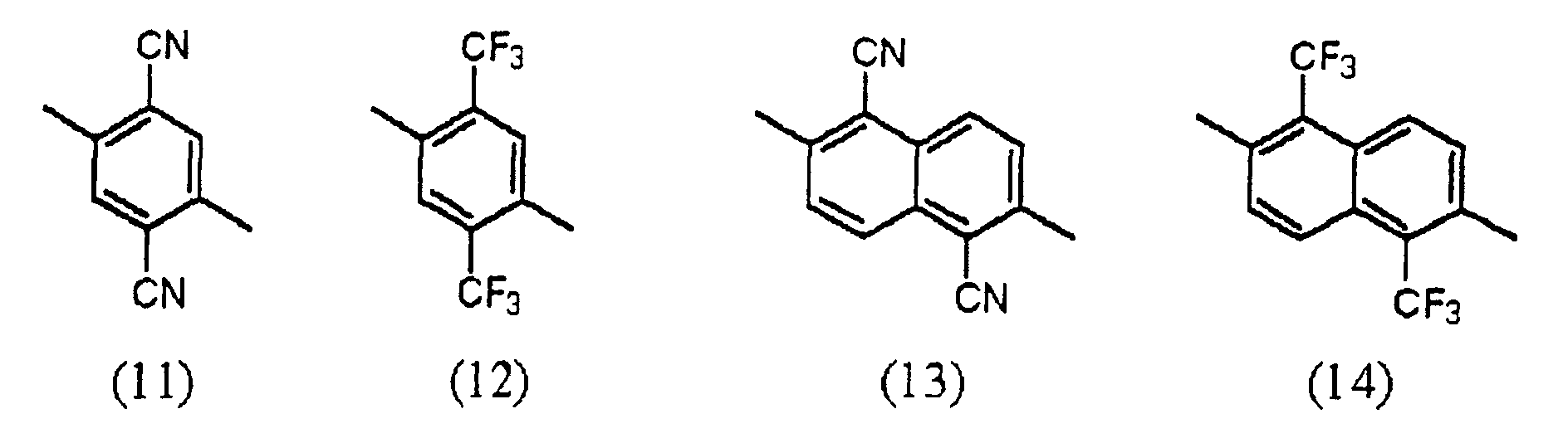 (where, in the general formulas (8) and (9) above, R11 and R12 are defined as above, R13 to R30 are defined as above (or a trifluoromethyl group if defined as fluoroalkyl groups).
- The organic electroluminescent element as defined in Claim 21, wherein the organic layer is of organic multilayer structure composed of a hole transfer layer and an electron transfer layer, with at least the electron transfer layer in the organic multilayer structure being the layer formed from a light emitting mixture containing at least one species of the aminostyryl compounds represented by the general formula [I] above.
- The organic electroluminescent element as defined in Claim 21, wherein the organic layer is of organic multilayer structure composed of a hole transfer layer and an electron transfer layer, with at least the hole transfer layer in the organic multilayer structure being the layer formed from a light emitting mixture containing at least one species of the aminostyryl compounds represented by the general formula [I] above.
- The organic electroluminescent element as defined in Claim 21, wherein the organic layer is of organic multilayer structure composed of a hole transfer layer and an electron transfer layer, with the hole transfer layer being a layer of a light-emitting mixture containing at least one species of the aminostyryl compounds represented by the general formula [I] above, and the electron transfer layer being a layer of a light-emitting mixture containing at least one species of the aminostyryl compounds represented by the general formula [I] above, and there exists a hole blocking layer adjacent to the cathode of the layer formed from a light-emitting mixture capable of electron transfer.
- The organic electroluminescent element as defined in Claim 21, wherein the organic layer is of organic multilayer structure composed of a hole transfer layer, a luminescent layer, and an electron transfer layer, with at least the luminescent layer in the organic multilayer structure being the layer of a light-emitting mixture containing at least one species of the aminostyryl compounds represented by the general formula [I] above.
- A luminescent device in which is used the organic electroluminescent element as defined in any of Claims 21 to 26.
- The luminescent device as defined in Claim 27, which is constructed for use as a display device.
- An organic electroluminescent element in which an organic layer having a luminescent region is arranged between an anode and a cathode, characterized in that said organic layer is constructed of at least one layer formed from a mixture containing at least one species of the aminostyryl compounds represented by the following structural formulas (15)-1 to (15)-12, (16)-1 to (16)-12, (17)-1 to (17)-6, and (18)-1 to (18)-6, and there exists a hole blocking layer adjacent to the cathode of the layer formed from a light-emitting mixture.


- The organic electroluminescent element as defined in Claim 29, wherein the organic layer is of organic multilayer structure composed of a hole transfer layer and an electron transfer layer, with at least the electron transfer layer in the organic multilayer structure being the layer of a light-emitting mixture containing at least one species of the aminostyryl compounds.
- The organic electroluminescent element as defined in Claim 29, wherein the organic layer is of organic multilayer structure composed of a hole transfer layer and an electron transfer layer, with at least the hole transfer layer in the organic multilayer structure being the layer of a light-emitting mixture containing at least one species of the aminostyryl compounds.
- The organic electroluminescent element as defined in Claim 29, wherein the organic layer is of organic multilayer structure composed of a hole transfer layer and an electron transfer layer, with the hole transfer layer being the layer of a light-emitting mixture containing at least one species of the aminostyryl compounds mentioned above, and the electron transfer layer being the layer of a light-emitting mixture containing at least one species of the aminostyryl compounds mentioned above, and there exists the hole blocking layer adjacent to the cathode of the layer formed from a light-emitting mixture capable of electron transfer.
- The organic electroluminescent element as defined in Claim 29, wherein the organic layer is of organic multilayer structure composed of a hole transfer layer, a luminescent layer, and an electron transfer layer, with at least the luminescent layer in the organic multilayer structure being the layer of a light-emitting mixture containing at least one species of the aminostyryl compounds.
- The organic electroluminescent element as defined in Claim 29, wherein the organic layer is constructed such that said at least one layer therein is the layer of a light-emitting mixture containing at least one species of the aminostyryl compounds and a dye emitting red light which has the emission maximum in the range of 600 nm or more.
- The organic electroluminescent element as defined in Claim 34, wherein the organic layer is of organic multilayer structure composed of a hole transfer layer and an electron transfer layer, with said at least one layer in the laminate structure being then electron transfer layer.
- The organic electroluminescent element as defined in Claim 34, wherein the organic layer is of organic multilayer structure composed of a hole transfer layer and an electron transfer layer, with said at least one layer in the laminate structure being the hole transfer layer.
- The organic electroluminescent element as defined in Claim 29, wherein the organic layer is of organic multilayer structure composed of a hole transfer layer and an electron transfer layer, with the hole transfer layer being the layer of a light-emitting mixture containing at least one species of the aminostyryl compounds and a dye emitting red light which has the emission maximum in the region beyond 600 nm, and the electron transfer layer being a layer of a light-emitting mixture containing at least one species of the aminostyryl compounds and a dye emitting red light which has the emission maximum in a range of 600 nm or more, and there exists the hole blocking layer adjacent to the cathode of the layer formed from a light-emitting mixture capable of electron transfer.
- The organic electroluminescent element as defined in Claim 29, wherein the organic layer is of organic multilayer structure composed of a hole transfer layer, a luminescent layer, and an electron transfer layer, with the luminescent layer being the layer of a light-emitting mixture containing at least one species of the aminostyryl compounds and a dye emitting red light which has the emission maximum in a range of 600 nm or more.
- A luminescent device in which is used the organic electroluminescent element as defined in any of Claims 29 to 38.
- The luminescent device as defined in Claim 39, which is constructed for use as a display device.
- An organic electroluminescent element in which an organic layer having a luminescent region is arranged between an anode and a cathode, characterized in that said organic layer is constructed of at least one layer formed from a aminostyryl compound represented by the following general formula [I] and there exists a hole blocking layer adjacent to the cathode of the layer of aminostyryl compound.
Y1-CH=CH-X1-CH=CH-Y2 (where, in the general formulas (1) to (3) above, at least one of R1 to R4 is a group selected from halogen atoms, nitro groups, cyano groups, and fluoroalkyl groups, and others are groups selected from hydrogen atom, alkyl groups, aryl groups, alkoxyl groups, halogen atoms, nitro groups, cyano groups, and fluoroalkyl groups, which are identical or different; in the general formulas (4) to (7), at least one of R5 to R10 is a group selected from halogen atoms, nitro groups, cyano groups, and fluoroalkyl groups, and others are groups selected from hydrogen atom, alkyl groups, aryl groups, alkoxyl groups, halogen atoms, nitro groups, cyano groups, and fluoroalkyl groups, which are identical or different.)
Y1 is a group represented by the following general formula (8) or (9), and Y2 is a group represented by the following general formula (8), (9), or (10).(where, in the general formulas (8) to (10) above, R11 and R12 each is a group selected from a hydrogen atom, alkyl groups with optional substituents, and aryl groups with optional substituents, which are identical or different; and R13 to R35 each is a group selected from a hydrogen atom, alkyl groups with optional substituents, and aryl groups with optional substituents, alkoxyl groups with optional substituents, halogen atoms, nitro groups, cyano groups, and fluoroalkyl groups, which are identical or different.)
- The organic electroluminescent element as defined in Claim 41, wherein the general formula [I] is characterized in that X1 is a group represented by any one of the following structural formulas (11) to (14)and Y1 and Y2 each is a group represented by the following general formula (8) or (9).
 (where, in the general formulas (8) and (9) above, R11 and R12 are defined as above, R13 to R30 are defined as above (or a trifluoromethyl group if defined as fluoroalkyl groups).
- The organic electroluminescent element as defined in Claim 41, wherein the organic layer is of organic multilayer structure composed of a hole transfer layer and an electron transfer layer, with at least the electron transfer layer in the organic multilayer structure being a layer of said aminostyryl compound.
- The organic electroluminescent element as defined in Claim 41, wherein the organic layer is of organic multilayer structure composed of a hole transfer layer and an electron transfer layer, with at least the hole transfer layer in the organic multilayer structure being a layer of said aminostyryl compound.
- The organic electroluminescent element as defined in Claim 41, wherein the organic layer is of organic multilayer structure composed of a hole transfer layer and an electron transfer layer, with the hole transfer layer being a layer of said aminostyryl compound, and the electron transfer layer being a layer of said aminostyryl compound, and there exists the hole blocking layer adjacent to the cathode of the layer of aminostyryl compound capable of electron transfer.
- The organic electroluminescent element as defined in Claim 41, wherein the organic layer is of organic multilayer structure composed of a hole transfer layer, a luminescent layer, and an electron transfer layer, with at least the luminescent layer in the organic multilayer structure being a layer of said aminostyryl compound.
- A luminescent device in which is used the organic electroluminescent element as defined in any of Claims 41 to 46.
- The luminescent device as defined in Claim 47, which is constructed for use as a display device.
- An organic electroluminescent element in which an organic layer having a luminescent region is arranged between an anode and a cathode, characterized in that said organic layer is constructed of at least one layer formed from an aminostyryl compound selected from the aminostyryl compounds represented by the following structural formulas (15)-1 to (15)-12, (16)-1 to (16)-12, (17)-1 to (17)-6, and (18)-1 to (18)-6, and there exists a hole blocking layer adjacent to the cathode of the layer of said aminostyryl compound.

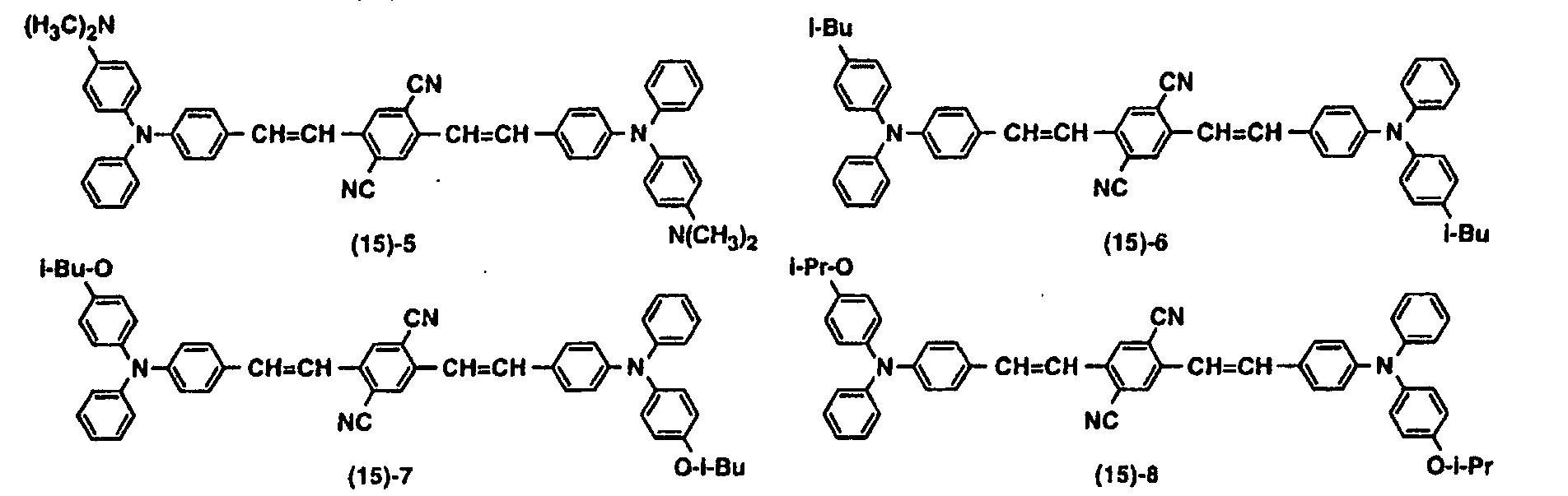


- The organic electroluminescent element as defined in Claim 49, wherein the organic layer is of organic multilayer structure composed of a hole transfer layer and an electron transfer layer, with at least the electron transfer layer in the organic multilayer structure being a layer of said aminostyryl compound.
- The organic electroluminescent element as defined in Claim 49, wherein the organic layer is of organic multilayer structure composed of a hole transfer layer and an electron transfer layer, with at least the hole transfer layer in the organic multilayer structure being a layer of said aminostyryl compound.
- The organic electroluminescent element as defined in Claim 49, wherein the organic layer is of organic multilayer structure composed of a hole transfer layer and an electron transfer layer, with the hole transfer layer being a layer of said aminostyryl compound, and the electron transfer layer being a layer of said aminostyryl compound, and there exists the hole blocking layer adjacent to the cathode of the layer of aminostyryl compound capable of electron transfer.
- The organic electroluminescent element as defined in Claim 49, wherein the organic layer is of organic multilayer structure composed of a hole transfer layer, a luminescent layer, and an electron transfer layer, with at least the luminescent layer in the organic multilayer structure being a layer of said aminostyryl compound.
- A luminescent device in which is used the organic electroluminescent element as defined in any of Claims 49 to 53.
- The luminescent device as defined in Claim 54, which is constructed for use as a display device.
Applications Claiming Priority (3)
| Application Number | Priority Date | Filing Date | Title |
|---|---|---|---|
| JP2000106430A JP2001291591A (en) | 2000-04-07 | 2000-04-07 | Organic electroluminescent element and luminescent device |
| JP2000106430 | 2000-04-07 | ||
| PCT/JP2001/003051 WO2001077253A1 (en) | 2000-04-07 | 2001-04-09 | Organic electroluminescent element and luminescent apparatus employing the same |
Publications (2)
| Publication Number | Publication Date |
|---|---|
| EP1205528A1 true EP1205528A1 (en) | 2002-05-15 |
| EP1205528A4 EP1205528A4 (en) | 2004-10-27 |
Family
ID=18619599
Family Applications (1)
| Application Number | Title | Priority Date | Filing Date |
|---|---|---|---|
| EP01919842A Withdrawn EP1205528A4 (en) | 2000-04-07 | 2001-04-09 | Organic electroluminescent element and luminescent apparatus employing the same |
Country Status (5)
| Country | Link |
|---|---|
| US (1) | US7255935B2 (en) |
| EP (1) | EP1205528A4 (en) |
| JP (1) | JP2001291591A (en) |
| KR (1) | KR100838094B1 (en) |
| WO (1) | WO2001077253A1 (en) |
Cited By (3)
| Publication number | Priority date | Publication date | Assignee | Title |
|---|---|---|---|---|
| EP1435384A2 (en) * | 2002-12-30 | 2004-07-07 | Lg Electronics Inc. | Red light emitting compounds for organic electroluminescent devices and organic electroluminescent devices using them |
| TWI402243B (en) * | 2010-01-06 | 2013-07-21 | Univ Nat Chiao Tung | Organic light emitting matterial |
| TWI421230B (en) * | 2010-01-06 | 2014-01-01 | Univ Nat Chiao Tung | Organic light emitting element and method of forming the same |
Families Citing this family (19)
| Publication number | Priority date | Publication date | Assignee | Title |
|---|---|---|---|---|
| JP2002220355A (en) * | 2001-01-26 | 2002-08-09 | Matsushita Electric Ind Co Ltd | Aromatic methylidene compound, aromatic aldehyde compound and methylstyryl compound to produce it, and method for producing them |
| JP2002220354A (en) * | 2001-01-26 | 2002-08-09 | Matsushita Electric Ind Co Ltd | Aromatic methylidene compound, aromatic aldehyde compound and methylstyryl compound to produce it, and method for producing them |
| JP2002212113A (en) * | 2001-01-24 | 2002-07-31 | Matsushita Electric Ind Co Ltd | Aromatic methylidene compound, aromatic aldehyde compound and methylstyryl compound for producing the same, and method for producing the compounds |
| JP2002212114A (en) * | 2001-01-24 | 2002-07-31 | Matsushita Electric Ind Co Ltd | Aromatic methylidene compound, aromatic aldehyde compound and methylstyryl compound for producing the same, and method for producing the compounds |
| JP2002212115A (en) * | 2001-01-24 | 2002-07-31 | Matsushita Electric Ind Co Ltd | Aromatic methylidene compound, aromatic aldehyde compound and methylstyryl compound for producing the same, and method for producing the compounds |
| JP2004006066A (en) * | 2002-04-15 | 2004-01-08 | Sony Corp | Organic electroluminescent element and luminescent apparatus |
| EP1498465A1 (en) * | 2002-04-24 | 2005-01-19 | Sony Corporation | Organic electroluminescent element |
| JP4001118B2 (en) | 2003-03-24 | 2007-10-31 | ソニー株式会社 | Organic electroluminescent device and amino monostyryl naphthalene compound |
| EP1651013A4 (en) * | 2003-07-08 | 2008-07-23 | Konica Minolta Holdings Inc | Organic electroluminescent device, illuminating device, and display |
| US7211823B2 (en) * | 2003-07-10 | 2007-05-01 | Universal Display Corporation | Organic light emitting device structure for obtaining chromaticity stability |
| US6885025B2 (en) * | 2003-07-10 | 2005-04-26 | Universal Display Corporation | Organic light emitting device structures for obtaining chromaticity stability |
| KR100811058B1 (en) * | 2005-05-11 | 2008-03-06 | (주)루디스 | A highly polymerized compound for emitting light and organic electroluminecent diode using that compound |
| KR100707357B1 (en) * | 2005-06-23 | 2007-04-13 | (주)그라쎌 | Precursors of organometallic compounds for electroluminescent materials |
| KR100736619B1 (en) * | 2005-10-12 | 2007-07-09 | 엘지전자 주식회사 | Organic electroluminescence devices |
| US7352125B2 (en) | 2005-12-21 | 2008-04-01 | Lg.Philips Lcd Co., Ltd. | Organic light emitting devices with hole impeding materials |
| WO2007132965A1 (en) * | 2006-05-12 | 2007-11-22 | Cheong-A Baek | High brightness electro luminescence device and method for manufacturing thereof |
| KR100924144B1 (en) | 2008-06-05 | 2009-10-28 | 삼성모바일디스플레이주식회사 | OLED and Method for fabricating the Same |
| PT3533601T (en) * | 2018-03-01 | 2022-08-09 | Bayerische Motoren Werke Ag | Composite structure for an airbag cover and sewn product with the composite structure |
| CN109742251B (en) * | 2019-01-08 | 2022-05-13 | 京东方科技集团股份有限公司 | OLED device, display panel and display device |
Citations (4)
| Publication number | Priority date | Publication date | Assignee | Title |
|---|---|---|---|---|
| EP0929104A2 (en) * | 1998-01-09 | 1999-07-14 | Sony Corporation | Electroluminescence device and process for producing the same |
| EP0954205A2 (en) * | 1998-03-24 | 1999-11-03 | Sony Corporation | Organic eletroluminescent device and method for producing it |
| EP1073128A2 (en) * | 1999-07-30 | 2001-01-31 | Sony Corporation | Organic electroluminescent device |
| EP1092704A2 (en) * | 1999-10-06 | 2001-04-18 | Sony Corporation | Bis (aminostyryl) naphtalene compounds, synthesis intermediates thereof, and process for production thereof |
Family Cites Families (13)
| Publication number | Priority date | Publication date | Assignee | Title |
|---|---|---|---|---|
| US5130603A (en) * | 1989-03-20 | 1992-07-14 | Idemitsu Kosan Co., Ltd. | Organic electroluminescence device |
| JPH07119407B2 (en) | 1989-03-20 | 1995-12-20 | 出光興産株式会社 | Electroluminescent device |
| JP3069139B2 (en) * | 1990-03-16 | 2000-07-24 | 旭化成工業株式会社 | Dispersion type electroluminescent device |
| JPH061973A (en) * | 1992-06-18 | 1994-01-11 | Konica Corp | Organic electroluminescent element |
| JP3852509B2 (en) * | 1998-01-09 | 2006-11-29 | ソニー株式会社 | Electroluminescent device and manufacturing method thereof |
| JP3852518B2 (en) * | 1998-05-18 | 2006-11-29 | ソニー株式会社 | Organic electroluminescence device |
| JP3852517B2 (en) * | 1998-05-18 | 2006-11-29 | ソニー株式会社 | Organic electroluminescence device |
| JP3852520B2 (en) * | 1998-06-26 | 2006-11-29 | ソニー株式会社 | Organic electroluminescence device |
| JP3555736B2 (en) * | 1998-06-26 | 2004-08-18 | ソニー株式会社 | Organic electroluminescent device |
| JP2000012225A (en) * | 1998-06-26 | 2000-01-14 | Sony Corp | Organic electroluminescent element |
| US6525212B1 (en) * | 1998-12-07 | 2003-02-25 | Sony Corporation | Bis(aminostyryl)benzene compounds and synthetic intermediates thereof, and process for preparing the compounds and intermediates |
| US6492557B1 (en) * | 1999-10-06 | 2002-12-10 | Sony Corporation | Bis (aminostyryl) naphthalene compound, synthesis intermediate thereof, and process for production thereof |
| US6660411B2 (en) * | 2000-09-20 | 2003-12-09 | Mitsubishi Chemical Corporation | Organic electroluminescent device |
-
2000
- 2000-04-07 JP JP2000106430A patent/JP2001291591A/en active Pending
-
2001
- 2001-04-09 EP EP01919842A patent/EP1205528A4/en not_active Withdrawn
- 2001-04-09 WO PCT/JP2001/003051 patent/WO2001077253A1/en active Application Filing
- 2001-04-09 KR KR1020017015806A patent/KR100838094B1/en not_active IP Right Cessation
- 2001-04-09 US US10/009,021 patent/US7255935B2/en not_active Expired - Fee Related
Patent Citations (4)
| Publication number | Priority date | Publication date | Assignee | Title |
|---|---|---|---|---|
| EP0929104A2 (en) * | 1998-01-09 | 1999-07-14 | Sony Corporation | Electroluminescence device and process for producing the same |
| EP0954205A2 (en) * | 1998-03-24 | 1999-11-03 | Sony Corporation | Organic eletroluminescent device and method for producing it |
| EP1073128A2 (en) * | 1999-07-30 | 2001-01-31 | Sony Corporation | Organic electroluminescent device |
| EP1092704A2 (en) * | 1999-10-06 | 2001-04-18 | Sony Corporation | Bis (aminostyryl) naphtalene compounds, synthesis intermediates thereof, and process for production thereof |
Non-Patent Citations (4)
| Title |
|---|
| DATABASE WPI Section Ch, Week 199406 Derwent Publications Ltd., London, GB; Class E14, AN 1994-045617 XP002280249 -& JP 06 001973 A (KONICA CORP) 11 January 1994 (1994-01-11) * |
| DATABASE WPI Section Ch, Week 200007 Derwent Publications Ltd., London, GB; Class E14, AN 2000-081068 XP002280250 & JP 11 329730 A (SONY CORP) 30 November 1999 (1999-11-30) -& US 2001/033945 A1 (ISHIBASHI TADASHI ET AL) 25 October 2001 (2001-10-25) * |
| DATABASE WPI Section Ch, Week 200137 Derwent Publications Ltd., London, GB; Class A18, AN 2001-078086 XP002280251 & JP 2000 012225 A (SONY CORP) 14 January 2000 (2000-01-14) -& US 6 228 514 B1 (SHINICHIRO TAMURA ET AL) 8 May 2001 (2001-05-08) * |
| See also references of WO0177253A1 * |
Cited By (6)
| Publication number | Priority date | Publication date | Assignee | Title |
|---|---|---|---|---|
| EP1435384A2 (en) * | 2002-12-30 | 2004-07-07 | Lg Electronics Inc. | Red light emitting compounds for organic electroluminescent devices and organic electroluminescent devices using them |
| EP1435384A3 (en) * | 2002-12-30 | 2004-10-13 | Lg Electronics Inc. | Red light emitting compounds for organic electroluminescent devices and organic electroluminescent devices using them |
| EP1619230A1 (en) * | 2002-12-30 | 2006-01-25 | LG Electronics, Inc. | Red light emitting compounds for organic electroluminescent devices and organic electroluminescent devices using them |
| US7261952B2 (en) | 2002-12-30 | 2007-08-28 | Lg Electronics Inc. | Red color emitting compounds for organic electroluminescent device and an organic electroluminescent device using them |
| TWI402243B (en) * | 2010-01-06 | 2013-07-21 | Univ Nat Chiao Tung | Organic light emitting matterial |
| TWI421230B (en) * | 2010-01-06 | 2014-01-01 | Univ Nat Chiao Tung | Organic light emitting element and method of forming the same |
Also Published As
| Publication number | Publication date |
|---|---|
| WO2001077253A1 (en) | 2001-10-18 |
| JP2001291591A (en) | 2001-10-19 |
| US7255935B2 (en) | 2007-08-14 |
| EP1205528A4 (en) | 2004-10-27 |
| KR100838094B1 (en) | 2008-06-13 |
| KR20020026873A (en) | 2002-04-12 |
| US20020106530A1 (en) | 2002-08-08 |
Similar Documents
| Publication | Publication Date | Title |
|---|---|---|
| JP4655410B2 (en) | Organic electroluminescence device | |
| JP3852552B2 (en) | Organic electroluminescence device | |
| EP1205528A1 (en) | Organic electroluminescent element and luminescent apparatus employing the same | |
| JP2000173774A (en) | Organic electric field light-emitting element | |
| EP1072668B1 (en) | Organic electroluminescent device | |
| JP2002134276A (en) | Organic electric field light emitting device | |
| EP0960927B1 (en) | Organic electroluminescent device | |
| JP3820752B2 (en) | Organic electroluminescence device | |
| JP2000091073A (en) | Organic electroluminescence element | |
| JP3852517B2 (en) | Organic electroluminescence device | |
| JP3555736B2 (en) | Organic electroluminescent device | |
| EP0985719B1 (en) | Organic electroluminescent device | |
| JP2000012225A (en) | Organic electroluminescent element | |
| JP2000012228A (en) | Organic electroluminescent element | |
| JP3852520B2 (en) | Organic electroluminescence device | |
| JP2000173773A (en) | Organic electric field light-emitting element | |
| JP2000091075A (en) | Organic electroluminescence element | |
| JP2000091074A (en) | Organic electroluminescence element | |
| JP2000091076A (en) | Organic electroluminescence element | |
| KR20040102368A (en) | Organic Electroluminescence Device |
Legal Events
| Date | Code | Title | Description |
|---|---|---|---|
| PUAI | Public reference made under article 153(3) epc to a published international application that has entered the european phase |
Free format text: ORIGINAL CODE: 0009012 |
|
| 17P | Request for examination filed |
Effective date: 20011220 |
|
| AK | Designated contracting states |
Kind code of ref document: A1 Designated state(s): AT BE CH CY DE DK ES FI FR GB GR IE IT LI LU MC NL PT SE TR |
|
| RBV | Designated contracting states (corrected) |
Designated state(s): DE FR GB |
|
| A4 | Supplementary search report drawn up and despatched |
Effective date: 20040903 |
|
| 17Q | First examination report despatched |
Effective date: 20061129 |
|
| STAA | Information on the status of an ep patent application or granted ep patent |
Free format text: STATUS: THE APPLICATION IS DEEMED TO BE WITHDRAWN |
|
| 18D | Application deemed to be withdrawn |
Effective date: 20121101 |