US7235796B2 - Method and apparatus for the generation of anionic and neutral particulate beams and a system using same - Google Patents
Method and apparatus for the generation of anionic and neutral particulate beams and a system using same Download PDFInfo
- Publication number
- US7235796B2 US7235796B2 US10/995,370 US99537004A US7235796B2 US 7235796 B2 US7235796 B2 US 7235796B2 US 99537004 A US99537004 A US 99537004A US 7235796 B2 US7235796 B2 US 7235796B2
- Authority
- US
- United States
- Prior art keywords
- electrical potential
- duct
- neutral particles
- electrically neutral
- heating element
- Prior art date
- Legal status (The legal status is an assumption and is not a legal conclusion. Google has not performed a legal analysis and makes no representation as to the accuracy of the status listed.)
- Expired - Fee Related, expires
Links
- 238000000034 method Methods 0.000 title claims abstract description 186
- 230000007935 neutral effect Effects 0.000 title claims abstract description 175
- 125000000129 anionic group Chemical group 0.000 title claims abstract description 72
- 239000002245 particle Substances 0.000 claims abstract description 172
- 150000001450 anions Chemical class 0.000 claims abstract description 119
- 238000010438 heat treatment Methods 0.000 claims abstract description 100
- 239000000126 substance Substances 0.000 claims abstract description 47
- 230000001133 acceleration Effects 0.000 claims abstract description 43
- 239000000463 material Substances 0.000 claims description 111
- 229910003472 fullerene Inorganic materials 0.000 claims description 83
- XMWRBQBLMFGWIX-UHFFFAOYSA-N C60 fullerene Chemical class C12=C3C(C4=C56)=C7C8=C5C5=C9C%10=C6C6=C4C1=C1C4=C6C6=C%10C%10=C9C9=C%11C5=C8C5=C8C7=C3C3=C7C2=C1C1=C2C4=C6C4=C%10C6=C9C9=C%11C5=C5C8=C3C3=C7C1=C1C2=C4C6=C2C9=C5C3=C12 XMWRBQBLMFGWIX-UHFFFAOYSA-N 0.000 claims description 75
- 239000003795 chemical substances by application Substances 0.000 claims description 40
- OKTJSMMVPCPJKN-UHFFFAOYSA-N Carbon Chemical compound [C] OKTJSMMVPCPJKN-UHFFFAOYSA-N 0.000 claims description 28
- 239000000203 mixture Substances 0.000 claims description 25
- FJDQFPXHSGXQBY-UHFFFAOYSA-L caesium carbonate Chemical compound [Cs+].[Cs+].[O-]C([O-])=O FJDQFPXHSGXQBY-UHFFFAOYSA-L 0.000 claims description 21
- 230000003287 optical effect Effects 0.000 claims description 21
- 229910044991 metal oxide Inorganic materials 0.000 claims description 18
- 150000004706 metal oxides Chemical class 0.000 claims description 18
- 229910052799 carbon Inorganic materials 0.000 claims description 16
- 238000010276 construction Methods 0.000 claims description 16
- WUAPFZMCVAUBPE-UHFFFAOYSA-N rhenium atom Chemical compound [Re] WUAPFZMCVAUBPE-UHFFFAOYSA-N 0.000 claims description 16
- 239000000919 ceramic Substances 0.000 claims description 15
- PNEYBMLMFCGWSK-UHFFFAOYSA-N aluminium oxide Inorganic materials [O-2].[O-2].[O-2].[Al+3].[Al+3] PNEYBMLMFCGWSK-UHFFFAOYSA-N 0.000 claims description 14
- 230000015572 biosynthetic process Effects 0.000 claims description 13
- 229910052702 rhenium Inorganic materials 0.000 claims description 12
- 229910000024 caesium carbonate Inorganic materials 0.000 claims description 11
- 229910002804 graphite Inorganic materials 0.000 claims description 11
- 239000010439 graphite Substances 0.000 claims description 11
- 229910052582 BN Inorganic materials 0.000 claims description 10
- PZNSFCLAULLKQX-UHFFFAOYSA-N Boron nitride Chemical compound N#B PZNSFCLAULLKQX-UHFFFAOYSA-N 0.000 claims description 10
- 238000004458 analytical method Methods 0.000 claims description 10
- 150000001722 carbon compounds Chemical class 0.000 claims description 10
- 230000008018 melting Effects 0.000 claims description 10
- 238000002844 melting Methods 0.000 claims description 10
- TWNQGVIAIRXVLR-UHFFFAOYSA-N oxo(oxoalumanyloxy)alumane Chemical compound O=[Al]O[Al]=O TWNQGVIAIRXVLR-UHFFFAOYSA-N 0.000 claims description 10
- RVTZCBVAJQQJTK-UHFFFAOYSA-N oxygen(2-);zirconium(4+) Chemical compound [O-2].[O-2].[Zr+4] RVTZCBVAJQQJTK-UHFFFAOYSA-N 0.000 claims description 10
- CYRMSUTZVYGINF-UHFFFAOYSA-N trichlorofluoromethane Chemical compound FC(Cl)(Cl)Cl CYRMSUTZVYGINF-UHFFFAOYSA-N 0.000 claims description 10
- 229910001928 zirconium oxide Inorganic materials 0.000 claims description 10
- 230000003247 decreasing effect Effects 0.000 claims description 9
- 239000012634 fragment Substances 0.000 claims description 9
- 238000006555 catalytic reaction Methods 0.000 claims description 8
- 238000005530 etching Methods 0.000 claims description 7
- 238000005468 ion implantation Methods 0.000 claims description 7
- 238000001459 lithography Methods 0.000 claims description 7
- 238000003786 synthesis reaction Methods 0.000 claims description 7
- 238000000427 thin-film deposition Methods 0.000 claims description 7
- 238000010009 beating Methods 0.000 claims 1
- 150000002500 ions Chemical class 0.000 description 36
- 238000010884 ion-beam technique Methods 0.000 description 15
- -1 fullerene ion Chemical class 0.000 description 14
- 230000008569 process Effects 0.000 description 11
- 230000004907 flux Effects 0.000 description 8
- 239000007789 gas Substances 0.000 description 7
- 238000001228 spectrum Methods 0.000 description 7
- 238000001819 mass spectrum Methods 0.000 description 6
- 239000000843 powder Substances 0.000 description 6
- 239000012190 activator Substances 0.000 description 5
- TVFDJXOCXUVLDH-UHFFFAOYSA-N caesium atom Chemical compound [Cs] TVFDJXOCXUVLDH-UHFFFAOYSA-N 0.000 description 5
- KLZUFWVZNOTSEM-UHFFFAOYSA-K Aluminium flouride Chemical compound F[Al](F)F KLZUFWVZNOTSEM-UHFFFAOYSA-K 0.000 description 4
- PXHVJJICTQNCMI-UHFFFAOYSA-N Nickel Chemical compound [Ni] PXHVJJICTQNCMI-UHFFFAOYSA-N 0.000 description 4
- 229910052792 caesium Inorganic materials 0.000 description 4
- BROHICCPQMHYFY-UHFFFAOYSA-N caesium chromate Chemical compound [Cs+].[Cs+].[O-][Cr]([O-])(=O)=O BROHICCPQMHYFY-UHFFFAOYSA-N 0.000 description 4
- 238000003795 desorption Methods 0.000 description 4
- 238000001514 detection method Methods 0.000 description 4
- 230000005264 electron capture Effects 0.000 description 4
- 238000000605 extraction Methods 0.000 description 4
- 238000000752 ionisation method Methods 0.000 description 4
- 238000004519 manufacturing process Methods 0.000 description 4
- 238000005259 measurement Methods 0.000 description 4
- 238000012986 modification Methods 0.000 description 4
- 230000004048 modification Effects 0.000 description 4
- 230000004913 activation Effects 0.000 description 3
- 150000001793 charged compounds Polymers 0.000 description 3
- 230000007423 decrease Effects 0.000 description 3
- 230000000694 effects Effects 0.000 description 3
- 230000005684 electric field Effects 0.000 description 3
- 239000003574 free electron Substances 0.000 description 3
- 230000003993 interaction Effects 0.000 description 3
- 239000003870 refractory metal Substances 0.000 description 3
- 239000007787 solid Substances 0.000 description 3
- 238000005011 time of flight secondary ion mass spectroscopy Methods 0.000 description 3
- 238000002042 time-of-flight secondary ion mass spectrometry Methods 0.000 description 3
- 108091092878 Microsatellite Proteins 0.000 description 2
- 229910052783 alkali metal Inorganic materials 0.000 description 2
- 150000001340 alkali metals Chemical group 0.000 description 2
- 125000004429 atom Chemical group 0.000 description 2
- 239000002041 carbon nanotube Substances 0.000 description 2
- 229910021393 carbon nanotube Inorganic materials 0.000 description 2
- 238000006243 chemical reaction Methods 0.000 description 2
- 230000003111 delayed effect Effects 0.000 description 2
- 238000011161 development Methods 0.000 description 2
- 238000010494 dissociation reaction Methods 0.000 description 2
- 230000005593 dissociations Effects 0.000 description 2
- 238000009826 distribution Methods 0.000 description 2
- 238000010894 electron beam technology Methods 0.000 description 2
- 230000005686 electrostatic field Effects 0.000 description 2
- 230000005284 excitation Effects 0.000 description 2
- 238000010265 fast atom bombardment Methods 0.000 description 2
- 229910052759 nickel Inorganic materials 0.000 description 2
- 230000003068 static effect Effects 0.000 description 2
- 229910052715 tantalum Inorganic materials 0.000 description 2
- ZOKXTWBITQBERF-UHFFFAOYSA-N Molybdenum Chemical compound [Mo] ZOKXTWBITQBERF-UHFFFAOYSA-N 0.000 description 1
- XDAASKLRQNGGAI-UHFFFAOYSA-N [Ta].[Re] Chemical compound [Ta].[Re] XDAASKLRQNGGAI-UHFFFAOYSA-N 0.000 description 1
- 239000003513 alkali Substances 0.000 description 1
- 239000012620 biological material Substances 0.000 description 1
- 125000004432 carbon atom Chemical group C* 0.000 description 1
- 238000003763 carbonization Methods 0.000 description 1
- 230000003197 catalytic effect Effects 0.000 description 1
- 238000000701 chemical imaging Methods 0.000 description 1
- 238000004140 cleaning Methods 0.000 description 1
- 239000011248 coating agent Substances 0.000 description 1
- 238000000576 coating method Methods 0.000 description 1
- 238000012937 correction Methods 0.000 description 1
- 230000006378 damage Effects 0.000 description 1
- 238000000354 decomposition reaction Methods 0.000 description 1
- 238000009792 diffusion process Methods 0.000 description 1
- 239000006185 dispersion Substances 0.000 description 1
- 238000010891 electric arc Methods 0.000 description 1
- 238000011067 equilibration Methods 0.000 description 1
- 230000008020 evaporation Effects 0.000 description 1
- 238000001704 evaporation Methods 0.000 description 1
- 238000002474 experimental method Methods 0.000 description 1
- 230000004992 fission Effects 0.000 description 1
- 238000013467 fragmentation Methods 0.000 description 1
- 238000006062 fragmentation reaction Methods 0.000 description 1
- PCHJSUWPFVWCPO-UHFFFAOYSA-N gold Chemical compound [Au] PCHJSUWPFVWCPO-UHFFFAOYSA-N 0.000 description 1
- 229910052737 gold Inorganic materials 0.000 description 1
- 239000010931 gold Substances 0.000 description 1
- 229910052735 hafnium Inorganic materials 0.000 description 1
- VBJZVLUMGGDVMO-UHFFFAOYSA-N hafnium atom Chemical compound [Hf] VBJZVLUMGGDVMO-UHFFFAOYSA-N 0.000 description 1
- 238000003384 imaging method Methods 0.000 description 1
- 239000012535 impurity Substances 0.000 description 1
- 238000009830 intercalation Methods 0.000 description 1
- 230000002687 intercalation Effects 0.000 description 1
- 238000000608 laser ablation Methods 0.000 description 1
- 239000007788 liquid Substances 0.000 description 1
- 238000004949 mass spectrometry Methods 0.000 description 1
- 229910052751 metal Inorganic materials 0.000 description 1
- 239000002184 metal Substances 0.000 description 1
- 229910001092 metal group alloy Inorganic materials 0.000 description 1
- 229910052750 molybdenum Inorganic materials 0.000 description 1
- 239000011733 molybdenum Substances 0.000 description 1
- YUSUJSHEOICGOO-UHFFFAOYSA-N molybdenum rhenium Chemical compound [Mo].[Mo].[Re].[Re].[Re] YUSUJSHEOICGOO-UHFFFAOYSA-N 0.000 description 1
- 230000000149 penetrating effect Effects 0.000 description 1
- 230000035515 penetration Effects 0.000 description 1
- 230000000979 retarding effect Effects 0.000 description 1
- 238000012552 review Methods 0.000 description 1
- DECCZIUVGMLHKQ-UHFFFAOYSA-N rhenium tungsten Chemical compound [W].[Re] DECCZIUVGMLHKQ-UHFFFAOYSA-N 0.000 description 1
- 238000000680 secondary ion mass spectrometry imaging Methods 0.000 description 1
- 230000035945 sensitivity Effects 0.000 description 1
- 230000002269 spontaneous effect Effects 0.000 description 1
- 238000004544 sputter deposition Methods 0.000 description 1
- 238000005478 sputtering type Methods 0.000 description 1
- 230000006641 stabilisation Effects 0.000 description 1
- 238000011105 stabilization Methods 0.000 description 1
- WTKKCYNZRWIVKL-UHFFFAOYSA-N tantalum Chemical compound [Ta+5] WTKKCYNZRWIVKL-UHFFFAOYSA-N 0.000 description 1
- GUVRBAGPIYLISA-UHFFFAOYSA-N tantalum atom Chemical compound [Ta] GUVRBAGPIYLISA-UHFFFAOYSA-N 0.000 description 1
- 238000012360 testing method Methods 0.000 description 1
- WFKWXMTUELFFGS-UHFFFAOYSA-N tungsten Chemical compound [W] WFKWXMTUELFFGS-UHFFFAOYSA-N 0.000 description 1
- 229910052721 tungsten Inorganic materials 0.000 description 1
- 239000010937 tungsten Substances 0.000 description 1
- 238000009834 vaporization Methods 0.000 description 1
- 230000008016 vaporization Effects 0.000 description 1
Images


Classifications
-
- H—ELECTRICITY
- H01—ELECTRIC ELEMENTS
- H01J—ELECTRIC DISCHARGE TUBES OR DISCHARGE LAMPS
- H01J49/00—Particle spectrometers or separator tubes
- H01J49/02—Details
- H01J49/10—Ion sources; Ion guns
- H01J49/16—Ion sources; Ion guns using surface ionisation, e.g. field-, thermionic- or photo-emission
-
- H—ELECTRICITY
- H01—ELECTRIC ELEMENTS
- H01J—ELECTRIC DISCHARGE TUBES OR DISCHARGE LAMPS
- H01J27/00—Ion beam tubes
- H01J27/02—Ion sources; Ion guns
- H01J27/20—Ion sources; Ion guns using particle beam bombardment, e.g. ionisers
-
- H—ELECTRICITY
- H01—ELECTRIC ELEMENTS
- H01J—ELECTRIC DISCHARGE TUBES OR DISCHARGE LAMPS
- H01J27/00—Ion beam tubes
- H01J27/02—Ion sources; Ion guns
- H01J27/26—Ion sources; Ion guns using surface ionisation, e.g. field effect ion sources, thermionic ion sources
-
- H—ELECTRICITY
- H01—ELECTRIC ELEMENTS
- H01J—ELECTRIC DISCHARGE TUBES OR DISCHARGE LAMPS
- H01J49/00—Particle spectrometers or separator tubes
- H01J49/02—Details
- H01J49/10—Ion sources; Ion guns
- H01J49/14—Ion sources; Ion guns using particle bombardment, e.g. ionisation chambers
-
- H—ELECTRICITY
- H05—ELECTRIC TECHNIQUES NOT OTHERWISE PROVIDED FOR
- H05H—PLASMA TECHNIQUE; PRODUCTION OF ACCELERATED ELECTRICALLY-CHARGED PARTICLES OR OF NEUTRONS; PRODUCTION OR ACCELERATION OF NEUTRAL MOLECULAR OR ATOMIC BEAMS
- H05H3/00—Production or acceleration of neutral particle beams, e.g. molecular or atomic beams
- H05H3/02—Molecular or atomic-beam generation, e.g. resonant beam generation
Definitions
- the present invention relates to the generation of particulate beams characterized by high brightness and small emission area, and more particularly, to an apparatus and method for the generation of neutral and anionic particulate beams. Even more particularly, the present invention generates anionic and neutral fullerene beams.
- the present invention also relates to a method for generating neutral and anionic particulate beams, and more particularly to a method for generating anionic and neutral fullerene beams.
- the present invention also relates to a system that utilizes a particulate beam for analyzing substances ejected from a surface of a sample bombarded with the particulate beam.
- Fullerenes are a newly discovered form of carbon.
- the fullerenes are a family of hollow (cage) all-carbon structures.
- C 60 is the most prominent member of this family.
- C 60 is a perfectly symmetrical molecule composed of 60 carbon atoms arranged on the surface of a sphere in an array of 12 pentagons and 20 hexagons (a soccer-ball molecule).
- C 60 has many unique properties but most relevant here arc its structural rigidity (closed cage) and its thermal and collisional stability.
- fullerenes are C 70 , C 76 and C 84 .
- Their structure is described in [“Science of fullerenes and carbon Nanotubes,” M. S. Dresselhaus et. al., Academic Press, San-Diego 1996] which is incorporated herein by reference.
- Fullerene cages are approximately 7–15 Angstroms in diameter. The molecules are relatively stable; the molecules dissociate at temperatures above 1000 C. Fullerenes sublime at much lower temperatures, i.e., a few hundred degrees C.
- the production of neutral and anionic particulate beams is of considerable importance in such diverse areas as atomic, molecular and plasma physics, thin film deposition, surface etching, ion implantation, submicron lithography, nano-electro-mechanical and nanophotonic system construction, new material synthesis, and electric propulsion devices.
- Applications utilizing anionic particulate beams find use in fundamental science areas, e.g., surface chemistry and catalysis, organic chemistry, and biology.
- FAB Flust Atom Bombardment
- TOF-SIMS Time Of Flight Secondary Ion Mass Spectrometry
- a typical prior art apparatus for the generation of molecular anions includes a monochromatic electron source for providing the low energy electron beam (0.1–2 eV) [E Illenberg et al., “Gaseous molecular ions. An Introduction to Elementary Processes Induced By Ionization” (Stenkopff/Springer, Darmstadt, Berlin), 1992].
- the electron beam is crossed at a right angle to a molecular beam effusing from a capillary.
- the capillary is connected to an oven containing a fullerene sample. The oven is kept at the temperature in the range of 600–800 K.
- Negative ions formed by electron capture are extracted from the reaction volume by a weak electric field and are accelerated to a given energy onto the entrance of the ion beam formation system.
- the main disadvantage of this method is low beam brightness due to the large ionization volume needed to generate high ion current and an inability to introduce a strong electrostatic field into the reaction volume as needed due to strong effects of external fields on trajectories and energy of electrons and depression of the ionization process.
- FIG. 1 is a schematic illustration of a prior art apparatus 20 for the generation of fullerene negative ions based on a surface ionization process.
- a surface ionization process a plurality of neutral molecules is adsorbed onto a hot surface with a low work function. A portion of the plurality of neutral molecules is then ionized as the molecules emitted from the surface.
- the prior art apparatus is described in Russian Patent No. 2074451 to L. N. Sidorov, et al.
- Apparatus 20 of FIG. 1 comprises an internal effusive cell 22 nested inside an external effusive cell 24 .
- Internal cell 22 has an effusive orifice 30 and contains a fullerene mixture powder 26 .
- External cell 24 also has an effusive orifice 32 and contains a material 28 that reduces the work function of its walls. In the reported method, material 28 is a mixture of AlF 3 +KF.
- Cells 22 and 24 are manufactured from nickel.
- Cell 22 and cell 24 are heated simultaneously so that the internal pressure of the nested cells 22 and 24 reaches the equilibrium vapor pressure of fullerene. Negative surface ionization of the plurality of fullerenes takes place on the walls of external cell 24 .
- the ionized molecules are extracted from orifice 32 on the front conical part of external cell 24 .
- the ionized molecules are accelerated by the applied electric field (not shown).
- the apparatus of FIG. 1 is disadvantageous for use in microprobe SLMS applications.
- the ion beam is of a low brightness and low ion current density ( ⁇ 5 ⁇ 10 ⁇ 7 A ⁇ cm ⁇ 2 ).
- the ionization efficiency of the apparatus depends on the equilibrium vapor pressure of the fullerene and activator molecules (AlF 3 +KF).
- the final ion beam current is difficult to control and adjust over a wide range because the ion current continues so long as activator molecules 28 exist in external cell 24 .
- an anionic particulate beam is generated by heating a nonreactive vessel containing a plurality of neutral particles to a temperature above an electron emission temperature so as to generate anionic particles.
- the anionic particles are accelerated out of the nonreactive vessel by a positive electrical potential applied in the front of the vessel.
- a neutral particulate beam is generated by ion-optically controlling manipulating of a plurality of anionic particles having undergone electron autodetachment from the anionic particulate beam.
- the ion-optical control and manipulation is effected by at least one procedure selected from the group consisting of extraction, acceleration, deflection and focusing.
- an apparatus for generating an anion beam comprising a duct defined by walls having an inner surface capable of sustaining a temperature above an electron emission temperature of the inner surface, so as to negatively charge electrically neutral particles being passed through the duct when the inner surface is heated to the temperature above the electron emission temperature; a heating element for heating the inner surface to the temperature above the electron emission temperature; and an acceleration electrode for optically manipulating and focusing the negatively charged particles into the anion beam.
- an apparatus for generating a neutral particulate beam comprising a duct defined by walls having an inner surface capable of sustaining a temperature above an electron emission temperature of the inner surface, so as to negatively charge electrically neutral particles being passed through the duct when the inner surface is heated to the temperature above the electron emission temperature; a heating element for heating the inner surface to the temperature above the electron emission temperature; and an acceleration electrode for optically manipulating the negatively charged particles into an anion beam, whereby at least a portion of the negatively charged particles undergo electron autodetachment so as to generate the neutral particulate beam.
- the walls comprise a material characterized by a maximum service temperature of 2000 K. According to further features in the described preferred embodiments, the walls comprise a material characterized by a minimum service temperature of 1200 K.
- the walls comprise a material characterized by a melting point above 2200 K.
- the walls comprise a material characterized by a high resistivity at room temperature, the resistivity decreasing by at least five orders of magnitude when the material is heated to approximately electron emission temperature.
- the walls comprise a material is characterized by chemical inertness up to the maximum service temperature of the walls.
- the walls comprise a material selected a group consisting of metal oxides (such as, but not limited to, aluminum oxide and zirconium oxide) graphite, boron-nitride ceramic and many other kinds of high temperature ceramics.
- the material comprises alumina.
- the material is a source of electrons.
- the material is selected such that a residue generated from the electrically neutral particles activates the material so as to increase electron emission.
- the material is selected such that a facilitating agent activates the material so as to increase electron emission.
- the facilitating agent is Cs 2 CrO 4 or Cs 2 CO 3 .
- the diameter of the duct is in the range of a few microns to a few millimeters, more preferably from 50 microns to 300 microns most preferably from of 100 microns to 160 microns.
- the electrically neutral particles comprise carbon particles. According to still further features in the described preferred embodiments, the electrically neutral particles comprise C 60 molecules.
- the electrically neutral particles comprise an aggregate of different molecules. According to still further features in the described preferred embodiments, the electrically neutral particles comprise a mixture of fullerenes.
- the electrically neutral particles are selected from a group consisting of I 2 , SF 6 , CFCl 3 , WF 6 , F, Cl, and perhallogenated carbon compounds.
- the body of the acceleration electrode comprises a centered orifice through which the beam emanates, said orifice being coaxial with an optical axis of the beam, and a central axis of the duct.
- the apparatus further comprises a protection electrode defining a protected region, wherein the protection electrode prevents emitted electrons from escaping the protected region.
- the body of the protection electrode comprises a centered orifice through which the beam emanates, the orifice being coaxial with an optical axis of the beam, and the center of the duct.
- the heating element is at a first electrical potential
- the protection electrode is at a second electrical potential, the first electrical potential being positive with respect to the second electrical potential
- the heating element is at a first electrical potential
- the protection electrode is at a second electrical potential, the first electrical potential being negative with respect to the second electrical potential
- the heating element comprises a rhenium ribbon, the ribbon wrapped around the walls, the ribbon electrically connected to a power supply.
- the heating element comprises a heat-conductive body, kept at an electrical potential difference from an electron source, the heat-conductive body and the electron source being designed and constructed such that electrons, emitted by the electron source, accelerate in the electrical potential difference and bombard the heat-conductive body to thereby heat the heat-conductive body.
- the heating element is at a first electrical potential
- the acceleration electrode is at a third electrical potential, the first electrical potential being negative with respect to the third electrical potential
- the apparatus further comprises one or more einzel lenses to focus the anionic beam.
- the apparatus further comprises one or more gating electrodes for pulsed beam mode operation.
- the apparatus further comprises deflector plates for raster scanning the anionic beam onto a surface.
- the apparatus further comprises a first ingress port and a second ingress port into the duct, wherein the first port enables the neutral particles to be passed through the duct and the second port enables a facilitator agent to be passed through the duct, and wherein a first flow rate of the neutral particles and a second flow rate of the facilitator agent through the duct are separately controllable.
- a method of generating an anion beam comprising passing electrically neutral particles through a duct being defined by walls having an inner surface, while heating the inner surface to a temperature above a electron emission temperature of the inner surface, so as to negatively charge the particles, so as to obtain negatively charged particles; and focusing the negatively charged particles into the anion beam.
- a method of generating a neutral particulate beam comprising passing electrically neutral particles through a duct being defined by walls having an inner surface, while heating the inner surface to a temperature above a electron emission temperature of the inner surface, so as to negatively charge the particles, so as to obtain negatively charged particles; focusing the negatively charged particles into an anion beam, whereby at least a portion of the negatively charged particles undergo electron autodetachment; so as to generate the neutral particulate beam.
- the method further comprises redirecting the anion beam so that a first axis characterizing the anion beam is displaced angularly from a second axis characterizing the neutral beam.
- the method further comprises deflecting electrons emitted from the heating elements and/or detached electrons from an axis characterizing the anion beam.
- the deflection is by a magnet field.
- the method further comprises passing a facilitating agent through the duct in a simultaneous fashion with the electrically neutral particles so as to enhance the yield of said negatively charged particles.
- the facilitating agent enhances the efficiency of said electron emission.
- the method further comprises raster scanning the anionic beam onto a surface for analysis.
- the method further comprises analyzing a plurality of fragments emitted from the surface as a result of the raster scanning so as to determine the chemical composition of the surface.
- the anion beam is used for an application selected from a group consisting of atomic physics, molecular physics, plasma physics, thin film deposition, surface etching, ion implantation, submicron lithography, nano-electro-mechanical system construction, nanophotonic system construction, new material synthesis, and electric propulsion devices, such as, but not limited to, ion engines for micro-satellites.
- the anion beam is used for an application selected from a group consisting of surface chemistry and catalysis, organic chemistry, biology, pharmacology and biotechnology.
- a system for analyzing substances ejected from the surface of a sample bombarded with an anion beam comprising: (a) an anion beam source, wherein the source comprises a duct defined by walls having an inner surface capable of sustaining a temperature above a electron emission temperature of the inner surface, so as to negatively charge electrically neutral particles being passed through the duct when the inner surface is heated to the temperature above the electron emission temperature; a heating element for heating the inner surface to the temperature above said electron emission temperature; and an acceleration electrode for optically manipulating the negatively charged particles into the anion beam, such that when the anion beam bombards the surface, the anion beam ejects substances of the surface; and (b) a detector for detecting the substances once ejected from the surface.
- a system for analyzing substances ejected from the surface of a sample bombarded with a neutral particulate beam comprising: (a) a neutral particulate beam source, wherein the source comprises a duct defined by walls having an inner surface capable of sustaining a temperature above a electron emission temperature of the inner surface, so as to negatively charge electrically neutral particles being passed through the duct when the inner surface is heated to the temperature above the electron emission temperature; a heating element for heating the inner surface to the temperature above the electron emission temperature; and an acceleration electrode for focusing the negatively charged particles into the anion beam, whereby at least a portion of the negatively charged particles undergo electron autodetachment so as to generate an energetic neutral particulate beam, such that when the neutral beam bombards the surface, the neutral beam ejects substances of the surface; and (b) a detector for detecting the substances once ejected from the surface.
- a neutral particulate beam source wherein the source comprises a duct defined by walls having an inner surface capable of sustaining a temperature above a
- a method for analyzing substances ejected from the surface of a sample bombarded with an anion beam comprising: (a) passing electrically neutral particles through a duct being defined by walls having an inner surface, while heating the inner surface to a temperature above a electron emission temperature of the inner surface, so as to negatively charge said particles, so as to obtain negatively charged particles; and focusing the negatively charged particles into the anion beam; and (b) detecting the substances once ejected from the surface.
- a method for analyzing substances ejected from the surface of a sample bombarded with a neutral particulate beam comprising: (a) passing electrically neutral particles through a duct being defined by walls having an inner surface, while heating the inner surface to a temperature above a electron emission temperature of the inner surface, so as to negatively charge the particles, so as to obtain negatively charged particles, focusing the negatively charged particles into the anion beam, and focusing from the anion beam a separate energetic neutral beam by electron autodetachment from a portion of the negatively charged particles; and (b) detecting the substances once ejected from the surface.
- the detector is an energy mass analyzer.
- the detector utilizes a wide energy window.
- the present invention successfully addresses the shortcomings of the presently known configurations by providing an apparatus and method for generating neutral and anionic particulate beams that enjoy properties far exceeding the prior art.
- Implementation of the method and set of the present invention involves performing or completing selected tasks or steps manually, automatically, or a combination thereof.
- several selected steps could be implemented by hardware or by software on any operating system of any firmware or a combination thereof.
- selected steps of the invention could be implemented as a chip or a circuit.
- selected steps of the invention could be implemented as a plurality of software instructions being executed by a computer using any suitable operating system.
- selected steps of the method and set of the invention could be described as being performed by a data processor, such as a computing platform for executing a plurality of instructions.
- FIG. 1 is a schematic illustration of a prior art apparatus for the generation of fullerene negative ions based on a surface ionization process.
- FIG. 2 is a schematic illustration of an ion source according to various exemplary embodiments of the present invention.
- FIG. 3 is a schematic illustration of a cross-sectional view of an ion source according to various exemplary embodiments of the present invention.
- FIG. 4 is a schematic illustration of a cross-sectional view of an ion source according to various exemplary embodiments of the present invention.
- FIG. 5 is a schematic illustration of an ion source employing a method of electron bombardment, according to various exemplary embodiments of the present invention.
- FIG. 6 is a schematic illustration of a cross-sectional view of the ion source of FIG. 5 , according to various exemplary embodiments of the present invention.
- FIG. 7 is a schematic illustration of a modification of the ion gun for use with a gaseous supply of neutral particles, according to various exemplary embodiments of the invention.
- FIG. 8 is a schematic illustration of the use of a facilitating mixture added, according to various exemplary embodiments of the present invention.
- FIG. 9 is a schematic illustration of a cross-sectional view of an alternate exemplary embodiment of the ion source according to the present invention.
- FIG. 10 is a schematic illustration of a cross-sectional view of an alternate exemplary embodiment of the ion source according to the present invention.
- FIG. 11 is an illustration of an experimental configuration for the detection of neutral fullerene molecules in accordance with various exemplary embodiments of the present invention.
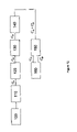
- FIG. 12 is a flowchart illustrating a method of generating an anionic beam in accord with various exemplary embodiments of the present invention.
- FIG. 13 is a graph illustrating a function relating the fraction of neutral fullerene molecules in total flux to source power and energy of the ion beam.
- FIG. 14A illustrates the mass spectrum of the negative fullerene ion beams for purified C 60 powder (99.5%).
- FIG. 14B illustrates the mass spectrum of the negative fullerene ion beams for a refined fullerene mixture.
- FIG. 15 illustrates the energy spectrum of the C 60 ⁇ negative ions produced by the ion source.
- FIG. 16 is a graph illustrating the C ⁇ ⁇ negative ion current as a function of the acceleration voltage, U acc .
- the present invention is of an apparatus and method for the generation of neutral and anionic particulate beams, anionic and neutral fullerene beams in particular, and uses thereof, in particular in a system and method for analyzing substances ejected from a surface of a sample bombarded with the neutral and anionic particulate beams.
- FIGS. 2 , 3 , 4 showing schematic illustrations of an apparatus 34 for generating anionic and neutral particulate beams according to various exemplary embodiments of the present invention.
- Apparatus 34 is both high vacuum and high pressure tight.
- the apparatus of various exemplary embodiments of the present invention comprises channel 59 (shown in FIGS. 3 and 4 ) ending with a duct 58 (shown in FIG. 4 ) defined by walls 60 having an inner surface 61 capable of sustaining a temperature above a electron emission temperature of the inner surface.
- Apparatus 34 further comprises a heating element 36 for heating inner surface 61 to the temperature above the electron emission temperature. Electrically neutral particles being passed through duct 58 as walls 60 are heated by heating element 36 above the electron emission temperature are negatively charged by a process of low-energy electron capture.
- An acceleration electrode 46 ion-optically manipulates the negatively charged particles into an anion beam. Any ion-optical manipulation can be employed, including, without limitation extraction, acceleration, deflection and focusing in any combination.
- the diameter of duct 58 is selected so as to optimize the generation of negatively charged particles within apparatus 34 . In various exemplary embodiments of the present invention, the diameter of the duct is in the range 50 microns to 300 microns. The diameter of the duct is preferably in the range of 100 microns to 160 microns.
- Walls 60 are comprised of a material characterized by high temperature stability, mechanical strength, imperviousness to gas and extreme high chemical inertness at high temperatures.
- the criterion for chemical inertness is of crucial importance in preventing high-temperature oven chemistry. Therefore, in various exemplary embodiments of the present invention, walls 60 comprise a material characterized by a maximum service temperature of about 2000 K and a minimum service temperature of about 1200 K. In various exemplary embodiments of the invention, walls 60 comprise a material having a melting point above 2200 K. Further, walls 60 comprise a material characterized by chemical inertness, preferably up to the maximum service temperature.
- walls 60 comprise a material characterized by a high resistivity at room temperature.
- the resistivity of the material decreases by at least five orders of magnitude when the material is heated to approximately electron emission temperature.
- the material serves a source of electrons.
- walls 60 comprise a material selected a group consisting of metal oxide (such as, but not limited to, aluminum oxide and zirconium oxide), graphite, boron-nitride ceramic and many other kinds of high temperature ceramics.
- metal oxide such as, but not limited to, aluminum oxide and zirconium oxide
- graphite such as, but not limited to, aluminum oxide and zirconium oxide
- boron-nitride ceramic such as, but not limited to, aluminum oxide and zirconium oxide
- walls 60 comprise alumina. Therefore, in a preferred embodiment of the present invention, apparatus 34 is constructed from a recrystallized, highly pure (ca. 99.8% or more) ultra high-density impervious alumina ceramic with a maximum service temperature of 2000 K. The flux of fullerene molecules through an alumina ceramic assembly, for example, is stable up to 1950 K [A.
- acceleration electrode 46 is emplaced in front of duct 58 .
- the body of acceleration electrode 46 comprises a centered orifice through which the beam emanates.
- the orifice is coaxial with the optical axis of the beam, and the central axis of duct 58 (dash-dot line on the FIG. 3 ).
- apparatus 34 further comprises a protection electrode 44 defining a protected region 45 .
- Protection electrode 44 serves for preventing the emitted electrons from escaping region 45 and penetrating into the regions of acceleration electrode 46 and grounded construction elements 54 . Additionally, protection electrode 44 acts as a heat shield. Similar to acceleration electrode 46 , protection electrode 44 is emplaced in front of duct 58 .
- the body of protection electrode 44 also comprises a centered orifice through which the beam emanates. Further, the orifice of protection electrode 44 is coaxial with the optical axis of the beam, and the central axis of duct 58 .
- heating element 36 comprises a rhenium ribbon, wrapped around walls 60 and connected to a, preferably D.C., power supply. Therefore, according to the presently preferred embodiment of the invention inner surface 61 is heated by resistive heating of the ribbon. Inner surface 61 is heated up to 1200–1750 K. Heating element 36 is maintained at a negative electrical potential relative to the electrical potential of acceleration electrode 46 . This negative electrical potential accelerates the anionic beam emanated from duct 58 .
- the heating is by electron bombardment, as further detailed hereinbelow with reference to FIGS. 5 and 6 .
- heating element 36 comprises a heat-conductive body 81 , preferably fitted to the external surface of walls 60 , and an electron source 80 .
- Heat-conductive body 81 can be, for example, a thin wall cylinder, which is preferably made of a refractory metal, such as, but not limited to, tungsten, molybdenum, rhenium, hafnium, tantalum, or refractory metal alloys, including, without limitation molybdenum-rhenium, tungsten-rhenium, tantalum-rhenium.
- Electron source 80 can be, for example, a roundly shaped filament (e.g., a ring, spiral, etc.) wrapped around heat-conductive body 81 .
- Electron source 80 is connected to a, preferably D.C., power supply and heated up to its characteristic electron emission temperature.
- Electron source 80 is preferably maintained at a large negative electrical potential with respect to the potential of heat-conductive body 81 .
- electrons emitted from electron source 80 are accelerated by an electric field generated by the potential difference between electron source 80 and heat-conductive body 81 .
- the accelerated electrons bombard the surface of electron source 81 thus transferring energy thereto. Consequently, the temperature of heat-conductive body 81 is increased and heat is transferred through wall 60 to inner surface 61 .
- electron source 81 is maintained at a negative electrical potential relative to the electrical potential of accelerator electrode 46 . The potential difference between electron source 81 and electrode 46 thus accelerates the anionic beam emanated from duct 58 .
- the negatively charged particles in the generated beam of the present invention may comprise anions as well as detached free electrons and electron emitted by heating element 36 .
- Protection electrode 44 is maintained at a small negative electrical potential with respect to the potential of heating element 36 by a D.C. power supply.
- the potential of protection electrode 44 prevents ingress of electrons emitted from heating element 36 to acceleration electrode 46 and construction elements 54 . Therefore, protection electrode 44 reduces the current load on the power supply.
- protection electrode 44 is maintained at a negative potential of about 1–2 V with respect to the electrical potential of heating element 36 .
- electrically neutral particles are placed into a replaceable ceramic container 42 .
- Container 42 is thereafter inserted into apparatus 34 so that the electrically neutral particles may be evaporated by an oven 49 .
- An assembly comprising apparatus 34 and container 42 is placed into a vacuum chamber 52 .
- oven 49 is heated by resistive heating of a tantalum or rhenium wire 48 wrapped around the exterior ceramic body of oven 49 .
- the control and stabilization of the temperature of oven 49 are preferably provided by a thermocouple 50 in contact with the external wall of oven 49 and incorporated into a feed back loop of the current supply to oven 49 .
- the temperature is maintained in the region of 700–950 K, depending on the required vapor pressure (about 0.1–0.5 Torr). In the preferred embodiment, the temperature is controlled to better than ⁇ 1 K.
- walls 60 and oven 49 are constructed of material with low thermoconductivity (such as, but not limited to, alumina) to provide thermal decoupling between oven 49 and walls 60 .
- This thermal decoupling enables a constant flux mode throughout the temperature range of walls 60 . Therefore, apparatus 34 enables independent control of the ion beam current level and internal (e.g., vibrational) energy of the molecular anions.
- the electrically neutral particles may constitute a liquid, solid or gas. In solid form, the electrically neutral particles may constitute a powder.
- the electrically neutral particles comprise carbon particles, for example, C 60 molecules; in another embodiment, the electrically neutral particles comprise a mixture of fullerenes; and in an additional embodiment, the electrically neutral particles comprise an aggregate of different molecules.
- the electrically neutral particles may exist in a gaseous form at room temperature.
- the particles arc selected, for example, from a group consisting of SF 6 , CFCl 3 , WF 6 , F, Cl, and perhalogenated carbon compounds.
- FIG. 7 is an illustration of a modification of apparatus 34 for use with a gaseous supply of neutral particles according to various exemplary embodiments of the present invention.
- a gas source may be connected via a seal flange 64 to apparatus 34 .
- Neutral gas atoms or molecules are conveyed out of container 70 through a valve 62 into apparatus 34 . Adjusting the pressure of the gas supply via valve 62 controls the ion beam current.
- the electrically neutral particles are being ionized by a process of low energy electron capture.
- the electrons are emitted from inner surface 61 of wall 60 .
- the material constituting walls 60 is characterized by a high resistivity at room temperature.
- the resistivity decreases by at least five orders of magnitude when the material is heated to approximately electron emission temperature. For example, at 1500 K, alumina becomes ten orders of magnitude more conductive than at room temperature. At these conditions, electron emission from inner surface 61 takes place.
- the anionic particles are then extracted and accelerated by an electrostatic field generated by accelerator electrode 46 .
- the material constituting walls 60 is selected such that the coating of inner surface 61 with carbonaceous overlayer results in a decrease of the surface work function, to increase thermionic electron emission.
- a facilitating agent is used to increase the efficiency of anion formation.
- the facilitating agent is an alkali metal vapor.
- the neutral molecules interact with the alkali atoms either in the gas phase or in a surface activation of inner surface 61 , with or without intercalation.
- Cesium is preferred for use with anionic fullerene formation because cesium offers the lowest ionization potential as compared to other alkali metals.
- Cesium is also preferred for use because of other properties of this element: (i) under heating, cesium chromate provides desorption of only cesium atoms (without any impurities); (ii) an optimal vapor pressure of cesium ( ⁇ 0.1 torr) consistent with the optimal vaporization temperature of fullerene molecules is achieved in the temperature region 700–900 K; (iii) in the optimal temperature range, cesium chromate is inactive towards to fullerene, therefore providing a long working time for this mixture.
- FIG. 8 illustrates an example of using a facilitating mixture 40 according to various exemplary embodiments of the present invention.
- mixture 40 of pure C 60 powder and cesium chromate in weight proportions of 80% C 60 +20% Cs 2 CrO 4 is placed inside crucible 42 .
- Crucible 42 is then placed into apparatus 34 .
- apparatus 34 further comprises a first ingress port 66 and a second ingress port 68 into duct 58 .
- First port 66 enables neutral particles to be passed through to duct 58 .
- Second port 68 enables a facilitator agent vapors to be passed through to duct 58 . Therefore, the individual flow rates of the neutral particles and the facilitator agent vapors through duct 58 are separately controllable by adjusting the vapor pressure of each gas. This configuration enables more efficient control of the anionic beam current.
- fullerene powder and an activator (Cs 2 CrO 4 ) are placed into individual crucibles 42 and heated by independent heaters 48 .
- the evaporated neutral fullerene molecules enter duct 58 via first ingress port 66 .
- the evaporated activator enters duct 58 via second ingress port 68 .
- crucibles 42 are operative to maintain the appropriate thermodynamic conditions for allowing the aforementioned evaporation of fullerene powder.
- Representative examples of the thermodynamic conditions of crucibles 42 include, without limitation temperature of about 700 to 1000 K and pressure of from about 0.001 to about 0.5 torr.
- apparatus 34 may also be used to generate a neutral particulate beam.
- at least a portion of the negatively charged particles (post-acceleration) comprising the anionic beam undergoes electron autodetachment so as to generate an energetic neutral particulate beam.
- a plurality of neutral fullerene molecules are generated after traversing duct 58 .
- fullerene molecules Under 0.1 torr vapor pressure, fullerene molecules have a mean free path of less than the diameter of channel 59 .
- the fullerene molecules spend approximately 0.8 millisecond inside channel 59 . This time is sufficient for the fullerene molecules to achieve translational and vibrational thermal equilibration because of the multiple (approximately 300–400) collisions of the molecules with inner surface 61 and with other molecules.
- E _ v ⁇ ( T ) ⁇ 7.47 + 0.01340 ⁇ ( T - 1000 ) 1500 ⁇ ⁇ K > T > 1000 ⁇ ⁇ K 14.17 + 0.01448 ⁇ ( T - 1500 ) 4000 ⁇ ⁇ K > T > 1500 ⁇ ⁇ K , where ⁇ is given in [eV] and T in [K] units.
- Anionic fullerene molecules effused from duct 58 have a minimal vibrational energy equal the sum of ⁇ ⁇ and energy EA acquired due to the capture of an extra electron (EA 2.65 eV—electron affinity of C 60 molecule).
- the vibrational energies of fullerene ions lie in the range of 12–21 eV.
- Such molecular anions have long-lived metastable states and therefore the auto-detachment of electrons along all paths of the anions into the ion optical system takes place. As a result, an energetic beam of neutral molecules is generated.
- apparatus 34 of FIG. 8 comprises one or more einzel lenses L 1 and L 2 to focus the anionic beam.
- a magnetic field, B is preferably applied to deflect detached electrons from the anion beam axis.
- apparatus 34 comprises one or more gating electrodes G for pulsed beam mode operation.
- apparatus 34 comprises deflector plates D 2 for raster scanning the anionic beam onto a surface.
- apparatus 34 further comprises intermediate correction plates D 1 and intermediate current collector C 1 .
- Surface Induced Dissociation (SID) was used for detection of the neutral beam.
- SID Surface Induced Dissociation
- the substances ejected from the surface are detected with an anionic fragment detector.
- an energy-mass analyzer EMA
- the detector uses wide energy windows for detection of these fragment anions.
- FIG. 12 is a flowchart illustrating a method for generating an anionic beam in accord with various exemplary embodiments of the present invention.
- the method begins at step 100 , and continues to step 110 , in which electrically neutral particles are passed through a duct defined by walls having an inner surface.
- step 120 in which the inner surface is heated to a temperature above its emission temperature.
- the process at step 120 occurs in a simultaneous fashion with the process at step 110 .
- the neutral particles become negatively charged.
- the negatively charged particles of step 120 are ion-optically controlled and manipulated into an anion beam at step 130 .
- the method continues at step 140 in which the energetic neutral particles are generated in field free space by the process of electron detachment of anions.
- the method preferably continues at step 150 , in which electrically charged and neutral particles are separated.
- step 160 the method ends.
- the method farther comprises the step of passing a facilitating agent through the duct in a simultaneous fashion with the passing of the electrically neutral particles through the duct so as to enhance the yield of the negatively charged particles.
- the method further comprises an additional step in which electrons emitted from the heating element and detached electrons are deflected from an axis characterizing the anion beam, for example, by applying a magnet field.
- the anion beam generated as a result of the processes of step 130 is redirected so that an axis characterizing the redirected anion beam is displaced angularly from an axis characterizing the neutral beam.
- the method further comprises raster scanning the anionic beam onto a surface for analysis. In various exemplary embodiments of the present invention, the method further comprises analyzing a plurality of species emitted from the surface as a result of the interaction of the scanning anion beam with the surface so as to determine its chemical composition.
- the anion beam of step 130 may be used for any application in the following non-exhaustive list: atomic physics, molecular physics, plasma physics, thin film deposition, surface etching, ion implantation, submicron lithography, nano-electro-mechanical system construction, nanophotonic system construction, new material synthesis, and electric propulsion devices, such as, but not limited to, ion engines for micro-satellites.
- either the anionic beam or the neutral particulate beam may be used for any application in the following non-exhaustive list: surface chemistry and catalysis, organic chemistry, biology, pharmacology and biotechnology.
- FIG. 13 illustrating the relationship of the fraction of neutral fullerene molecules in total flux to the source power and energy of the ion beam, as measured by the system of FIG. 11 .
- the total flux is defined to be the sum of neutral and negative charged molecules.
- the fraction of neutral fullerene molecules in the total flux depends both on the heating power applied to walls 60 (VxA) and on the beam energy (E o ). E o dependence is attributable to the difference in flight time of the fullerene molecules through the field free region A.
- the spectra are measured by a quadrupole mass-spectrometer.
- FIG. 14 a illustrates the mass spectra of an anionic fullerene beam generated from purified C 60 powder (99.5%).
- FIG. 14 b the mass spectra of an anionic beam generated from a refined fullerene mixture is illustrated.
- the mass spectra of the anionic beam generated from pure C 60 powder is dominated by C 60 ⁇ ions.
- FIG. 16 illustrates the fullerene anion current as a function of the acceleration voltage applied between walls 60 and acceleration electrode 46 . Measurements are presented for two different values of the heating power P (total power consumed by heating element 36 and oven 48 ) supplied to the source. As the graphs of FIG. 16 indicate, ion current may be controlled in a very wide range by controlling the power P applied to heating element 36 .
- the apparatus, system, and method of anionic beam generation and analysis and any apparatus, device and/or system which employs any embodiment of the apparatus described above may be employed on many objects which are to be imaged and/or otherwise analyzed.
Landscapes
- Physics & Mathematics (AREA)
- Engineering & Computer Science (AREA)
- Chemical & Material Sciences (AREA)
- Plasma & Fusion (AREA)
- Spectroscopy & Molecular Physics (AREA)
- Analytical Chemistry (AREA)
- Combustion & Propulsion (AREA)
- Physical Or Chemical Processes And Apparatus (AREA)
- Carbon And Carbon Compounds (AREA)
- Analysing Materials By The Use Of Radiation (AREA)
Abstract
Description
where
where the pre-exponential factor A=1.3×10¹¹ sec.−1 and the activation energy Ea=EA=2.65 eV. It is clear that the flux of neutral fullerene molecules is controlled over a wide range by variation of the nozzle temperature.
Claims (272)
Priority Applications (3)
| Application Number | Priority Date | Filing Date | Title |
|---|---|---|---|
| US10/995,370 US7235796B2 (en) | 2004-11-24 | 2004-11-24 | Method and apparatus for the generation of anionic and neutral particulate beams and a system using same |
| PCT/IL2005/001230 WO2006056975A2 (en) | 2004-11-24 | 2005-11-21 | Anionic and neutral particulate beams |
| EP05808221.5A EP1829436B1 (en) | 2004-11-24 | 2005-11-21 | Anionic and neutral particulate beams |
Applications Claiming Priority (1)
| Application Number | Priority Date | Filing Date | Title |
|---|---|---|---|
| US10/995,370 US7235796B2 (en) | 2004-11-24 | 2004-11-24 | Method and apparatus for the generation of anionic and neutral particulate beams and a system using same |
Publications (2)
| Publication Number | Publication Date |
|---|---|
| US20060118405A1 US20060118405A1 (en) | 2006-06-08 |
| US7235796B2 true US7235796B2 (en) | 2007-06-26 |
Family
ID=36498343
Family Applications (1)
| Application Number | Title | Priority Date | Filing Date |
|---|---|---|---|
| US10/995,370 Expired - Fee Related US7235796B2 (en) | 2004-11-24 | 2004-11-24 | Method and apparatus for the generation of anionic and neutral particulate beams and a system using same |
Country Status (3)
| Country | Link |
|---|---|
| US (1) | US7235796B2 (en) |
| EP (1) | EP1829436B1 (en) |
| WO (1) | WO2006056975A2 (en) |
Cited By (4)
| Publication number | Priority date | Publication date | Assignee | Title |
|---|---|---|---|---|
| US20090252887A1 (en) * | 2008-04-02 | 2009-10-08 | Raytheon Company | System and method for growing nanotubes with a specified isotope composition via ion implantation using a catalytic transmembrane |
| US20100044823A1 (en) * | 2006-02-10 | 2010-02-25 | Noble Peak Vision Corp. | Semiconductor photonic devices with enhanced responsivity and reduced stray light |
| US20100277051A1 (en) * | 2009-04-30 | 2010-11-04 | Scientific Instrument Services, Inc. | Emission filaments made from a rhenium alloy and method of manufacturing thereof |
| US20150090874A1 (en) * | 2012-03-28 | 2015-04-02 | Ulvac-Phi, Incorporated | Method and apparatus to provide parallel acquisition of mass spectrometry/mass spectrometry data |
Families Citing this family (5)
| Publication number | Priority date | Publication date | Assignee | Title |
|---|---|---|---|---|
| JP4497889B2 (en) * | 2003-10-29 | 2010-07-07 | アルバック・ファイ株式会社 | Electron spectroscopic analysis method and analyzer |
| US7235796B2 (en) * | 2004-11-24 | 2007-06-26 | Technion Research & Development Foundation Ltd. | Method and apparatus for the generation of anionic and neutral particulate beams and a system using same |
| JP2015185233A (en) * | 2014-03-20 | 2015-10-22 | 国立研究開発法人日本原子力研究開発機構 | Method for generating negative ion beam of fullerene and organic polymer |
| US10672602B2 (en) | 2014-10-13 | 2020-06-02 | Arizona Board Of Regents On Behalf Of Arizona State University | Cesium primary ion source for secondary ion mass spectrometer |
| EP3207636B1 (en) * | 2014-10-13 | 2019-12-04 | Arizona Board of Regents, a Body Corporate of the State of Arizona acting for and on behalf of Arizona State University | Cesium primary ion source for secondary ion mass spectrometer |
Citations (9)
| Publication number | Priority date | Publication date | Assignee | Title |
|---|---|---|---|---|
| US4564758A (en) * | 1984-02-01 | 1986-01-14 | Cameca | Process and device for the ionic analysis of an insulating sample |
| US4611120A (en) * | 1983-10-28 | 1986-09-09 | Bancroft G Michael | Suppression of molecular ions in secondary ion mass spectra |
| US4740697A (en) * | 1984-10-19 | 1988-04-26 | Kawasaki Steel Corporation | Secondary ion mass spectrometer |
| US4967078A (en) * | 1990-02-02 | 1990-10-30 | Genus, Inc. | Rutherford backscattering surface analyzer with 180-degree deflecting and focusing permanent magnet |
| US4968888A (en) * | 1989-07-05 | 1990-11-06 | The United States Of America As Represented By The United States Department Of Energy | Pulsed field sample neutralization |
| US5359254A (en) * | 1990-06-26 | 1994-10-25 | Research Institute Of Applied Mechanics And Electrodynamics | Plasma compensation cathode |
| US6303932B1 (en) * | 1997-11-20 | 2001-10-16 | Hitachi, Ltd. | Method and its apparatus for detecting a secondary electron beam image and a method and its apparatus for processing by using focused charged particle beam |
| GB2386747A (en) | 2001-11-08 | 2003-09-24 | Ionoptika Ltd | Fullerene ion gun |
| US20060118405A1 (en) * | 2004-11-24 | 2006-06-08 | Technion Research & Development Foundation Ltd. | Method and apparatus for the generation of anionic and neutral particulate beams and a system using same |
-
2004
- 2004-11-24 US US10/995,370 patent/US7235796B2/en not_active Expired - Fee Related
-
2005
- 2005-11-21 EP EP05808221.5A patent/EP1829436B1/en not_active Expired - Lifetime
- 2005-11-21 WO PCT/IL2005/001230 patent/WO2006056975A2/en not_active Ceased
Patent Citations (9)
| Publication number | Priority date | Publication date | Assignee | Title |
|---|---|---|---|---|
| US4611120A (en) * | 1983-10-28 | 1986-09-09 | Bancroft G Michael | Suppression of molecular ions in secondary ion mass spectra |
| US4564758A (en) * | 1984-02-01 | 1986-01-14 | Cameca | Process and device for the ionic analysis of an insulating sample |
| US4740697A (en) * | 1984-10-19 | 1988-04-26 | Kawasaki Steel Corporation | Secondary ion mass spectrometer |
| US4968888A (en) * | 1989-07-05 | 1990-11-06 | The United States Of America As Represented By The United States Department Of Energy | Pulsed field sample neutralization |
| US4967078A (en) * | 1990-02-02 | 1990-10-30 | Genus, Inc. | Rutherford backscattering surface analyzer with 180-degree deflecting and focusing permanent magnet |
| US5359254A (en) * | 1990-06-26 | 1994-10-25 | Research Institute Of Applied Mechanics And Electrodynamics | Plasma compensation cathode |
| US6303932B1 (en) * | 1997-11-20 | 2001-10-16 | Hitachi, Ltd. | Method and its apparatus for detecting a secondary electron beam image and a method and its apparatus for processing by using focused charged particle beam |
| GB2386747A (en) | 2001-11-08 | 2003-09-24 | Ionoptika Ltd | Fullerene ion gun |
| US20060118405A1 (en) * | 2004-11-24 | 2006-06-08 | Technion Research & Development Foundation Ltd. | Method and apparatus for the generation of anionic and neutral particulate beams and a system using same |
Non-Patent Citations (10)
Cited By (8)
| Publication number | Priority date | Publication date | Assignee | Title |
|---|---|---|---|---|
| US20100044823A1 (en) * | 2006-02-10 | 2010-02-25 | Noble Peak Vision Corp. | Semiconductor photonic devices with enhanced responsivity and reduced stray light |
| US20090252887A1 (en) * | 2008-04-02 | 2009-10-08 | Raytheon Company | System and method for growing nanotubes with a specified isotope composition via ion implantation using a catalytic transmembrane |
| US8252115B2 (en) * | 2008-04-02 | 2012-08-28 | Raytheon Company | System and method for growing nanotubes with a specified isotope composition via ion implantation using a catalytic transmembrane |
| US20100277051A1 (en) * | 2009-04-30 | 2010-11-04 | Scientific Instrument Services, Inc. | Emission filaments made from a rhenium alloy and method of manufacturing thereof |
| US8134290B2 (en) | 2009-04-30 | 2012-03-13 | Scientific Instrument Services, Inc. | Emission filaments made from a rhenium alloy and method of manufacturing thereof |
| US8226449B2 (en) | 2009-04-30 | 2012-07-24 | Scientific Instrument Services, Inc. | Method of manufacturing rhenium alloy emission filaments |
| US20150090874A1 (en) * | 2012-03-28 | 2015-04-02 | Ulvac-Phi, Incorporated | Method and apparatus to provide parallel acquisition of mass spectrometry/mass spectrometry data |
| US9159539B2 (en) * | 2012-03-28 | 2015-10-13 | Ulvac-Phi, Incorporated | Method and apparatus to provide parallel acquisition of mass spectrometry/mass spectrometry data |
Also Published As
| Publication number | Publication date |
|---|---|
| EP1829436B1 (en) | 2016-03-23 |
| WO2006056975A2 (en) | 2006-06-01 |
| WO2006056975A3 (en) | 2007-06-28 |
| US20060118405A1 (en) | 2006-06-08 |
| EP1829436A2 (en) | 2007-09-05 |
| EP1829436A4 (en) | 2010-11-24 |
Similar Documents
| Publication | Publication Date | Title |
|---|---|---|
| US7173252B2 (en) | Ionizer and method for gas-cluster ion-beam formation | |
| EP1683180B1 (en) | Carbon nanotube electron ionization sources | |
| US11764026B2 (en) | Electron source | |
| Tyunkov et al. | An experimental test-stand for investigation of electron-beam synthesis of dielectric coatings in medium vacuum pressure range | |
| US8405326B2 (en) | Method and apparatus for generating ion beam | |
| Li et al. | Space‐charge effects and ion distribution in plasma source mass spectrometry | |
| US7235796B2 (en) | Method and apparatus for the generation of anionic and neutral particulate beams and a system using same | |
| Skopinski et al. | Time-of-flight mass spectrometry of particle emission during irradiation with slow, highly charged ions | |
| Heiland et al. | 6. Ion Scattering and Secondary-Ion Mass Spectrometry | |
| Wayne et al. | The thermal ionization cavity (TIC) source: elucidation of possible mechanisms for enhanced ionization efficiency | |
| WO2017029754A1 (en) | Ion beam device and method for analyzing sample elements | |
| Van den Berg | Neutral and ion beam SIMS of non-conducting materials | |
| Zolotukhin et al. | Ion composition of beam plasma formed by electron beam evaporation of YSZ ceramic in medium vacuum | |
| US6617771B2 (en) | Electron ionization ion source | |
| Bhaskar et al. | Liquid metal ion source for cluster ions of metals and alloys: design and characteristics | |
| JPH0554809A (en) | Silicon ion source with built-in crucible | |
| Zolotukhin | Measurement of mass-to-charge beam plasma ion composition during electron beam evaporation of refractory materials in the forevacuum pressure range | |
| Belykh et al. | New Cs sputter ion source with polyatomic ion beams for secondary ion mass spectrometry applications | |
| Tyunkov et al. | The influence of the working gas composition on the mass-to-charge composition of ions in the beam plasma during the evaporation of an YSZ target by an electron beam | |
| Bekkerman et al. | Negative Fullerene ion gun for SIMS applications | |
| Calabrese et al. | Production of Group IIA atomic and molecular negative ion beams in a cesium-sputter negative ion source | |
| Pertsev | AN Petrangovskii and AF Ivanenko, Electronic Technol, Scient Tech | |
| Bentz et al. | Description and Applications fo a New Design Cs+ Ion Source on the COALA Ion Microprobe for Negative Ion SIMS | |
| Alton | Ion sources for accelerators | |
| Han et al. | Optimization of closed ion source for a high-sensitivity residual gas analyzer |
Legal Events
| Date | Code | Title | Description |
|---|---|---|---|
| AS | Assignment |
Owner name: TECHNION RESEARCH & DEVELOPMENT FOUNDATION LTD., I Free format text: ASSIGNMENT OF ASSIGNORS INTEREST;ASSIGNORS:KOLODNEY, ELI;BEKKERMAN, ANATOLY;TSIPINYUK, BORIS;REEL/FRAME:016035/0318 Effective date: 20041122 |
|
| STCF | Information on status: patent grant |
Free format text: PATENTED CASE |
|
| FEPP | Fee payment procedure |
Free format text: PAYOR NUMBER ASSIGNED (ORIGINAL EVENT CODE: ASPN); ENTITY STATUS OF PATENT OWNER: SMALL ENTITY |
|
| FPAY | Fee payment |
Year of fee payment: 4 |
|
| FPAY | Fee payment |
Year of fee payment: 8 |
|
| FEPP | Fee payment procedure |
Free format text: MAINTENANCE FEE REMINDER MAILED (ORIGINAL EVENT CODE: REM.); ENTITY STATUS OF PATENT OWNER: SMALL ENTITY |
|
| LAPS | Lapse for failure to pay maintenance fees |
Free format text: PATENT EXPIRED FOR FAILURE TO PAY MAINTENANCE FEES (ORIGINAL EVENT CODE: EXP.); ENTITY STATUS OF PATENT OWNER: SMALL ENTITY |
|
| STCH | Information on status: patent discontinuation |
Free format text: PATENT EXPIRED DUE TO NONPAYMENT OF MAINTENANCE FEES UNDER 37 CFR 1.362 |
|
| FP | Lapsed due to failure to pay maintenance fee |
Effective date: 20190626 |