US7227895B1 - System and method for generating decoded digital video image data - Google Patents
System and method for generating decoded digital video image data Download PDFInfo
- Publication number
- US7227895B1 US7227895B1 US10/014,689 US1468901A US7227895B1 US 7227895 B1 US7227895 B1 US 7227895B1 US 1468901 A US1468901 A US 1468901A US 7227895 B1 US7227895 B1 US 7227895B1
- Authority
- US
- United States
- Prior art keywords
- data
- picture
- picture data
- resolution
- pixel
- Prior art date
- Legal status (The legal status is an assumption and is not a legal conclusion. Google has not performed a legal analysis and makes no representation as to the accuracy of the status listed.)
- Active, expires
Links
Images


Classifications
-
- H—ELECTRICITY
- H04—ELECTRIC COMMUNICATION TECHNIQUE
- H04N—PICTORIAL COMMUNICATION, e.g. TELEVISION
- H04N19/00—Methods or arrangements for coding, decoding, compressing or decompressing digital video signals
- H04N19/50—Methods or arrangements for coding, decoding, compressing or decompressing digital video signals using predictive coding
- H04N19/59—Methods or arrangements for coding, decoding, compressing or decompressing digital video signals using predictive coding involving spatial sub-sampling or interpolation, e.g. alteration of picture size or resolution
-
- H—ELECTRICITY
- H04—ELECTRIC COMMUNICATION TECHNIQUE
- H04N—PICTORIAL COMMUNICATION, e.g. TELEVISION
- H04N19/00—Methods or arrangements for coding, decoding, compressing or decompressing digital video signals
- H04N19/10—Methods or arrangements for coding, decoding, compressing or decompressing digital video signals using adaptive coding
- H04N19/102—Methods or arrangements for coding, decoding, compressing or decompressing digital video signals using adaptive coding characterised by the element, parameter or selection affected or controlled by the adaptive coding
- H04N19/12—Selection from among a plurality of transforms or standards, e.g. selection between discrete cosine transform [DCT] and sub-band transform or selection between H.263 and H.264
- H04N19/122—Selection of transform size, e.g. 8x8 or 2x4x8 DCT; Selection of sub-band transforms of varying structure or type
-
- H—ELECTRICITY
- H04—ELECTRIC COMMUNICATION TECHNIQUE
- H04N—PICTORIAL COMMUNICATION, e.g. TELEVISION
- H04N19/00—Methods or arrangements for coding, decoding, compressing or decompressing digital video signals
- H04N19/10—Methods or arrangements for coding, decoding, compressing or decompressing digital video signals using adaptive coding
- H04N19/102—Methods or arrangements for coding, decoding, compressing or decompressing digital video signals using adaptive coding characterised by the element, parameter or selection affected or controlled by the adaptive coding
- H04N19/132—Sampling, masking or truncation of coding units, e.g. adaptive resampling, frame skipping, frame interpolation or high-frequency transform coefficient masking
-
- H—ELECTRICITY
- H04—ELECTRIC COMMUNICATION TECHNIQUE
- H04N—PICTORIAL COMMUNICATION, e.g. TELEVISION
- H04N19/00—Methods or arrangements for coding, decoding, compressing or decompressing digital video signals
- H04N19/10—Methods or arrangements for coding, decoding, compressing or decompressing digital video signals using adaptive coding
- H04N19/134—Methods or arrangements for coding, decoding, compressing or decompressing digital video signals using adaptive coding characterised by the element, parameter or criterion affecting or controlling the adaptive coding
- H04N19/157—Assigned coding mode, i.e. the coding mode being predefined or preselected to be further used for selection of another element or parameter
- H04N19/159—Prediction type, e.g. intra-frame, inter-frame or bidirectional frame prediction
-
- H—ELECTRICITY
- H04—ELECTRIC COMMUNICATION TECHNIQUE
- H04N—PICTORIAL COMMUNICATION, e.g. TELEVISION
- H04N19/00—Methods or arrangements for coding, decoding, compressing or decompressing digital video signals
- H04N19/10—Methods or arrangements for coding, decoding, compressing or decompressing digital video signals using adaptive coding
- H04N19/169—Methods or arrangements for coding, decoding, compressing or decompressing digital video signals using adaptive coding characterised by the coding unit, i.e. the structural portion or semantic portion of the video signal being the object or the subject of the adaptive coding
- H04N19/17—Methods or arrangements for coding, decoding, compressing or decompressing digital video signals using adaptive coding characterised by the coding unit, i.e. the structural portion or semantic portion of the video signal being the object or the subject of the adaptive coding the unit being an image region, e.g. an object
- H04N19/176—Methods or arrangements for coding, decoding, compressing or decompressing digital video signals using adaptive coding characterised by the coding unit, i.e. the structural portion or semantic portion of the video signal being the object or the subject of the adaptive coding the unit being an image region, e.g. an object the region being a block, e.g. a macroblock
-
- H—ELECTRICITY
- H04—ELECTRIC COMMUNICATION TECHNIQUE
- H04N—PICTORIAL COMMUNICATION, e.g. TELEVISION
- H04N19/00—Methods or arrangements for coding, decoding, compressing or decompressing digital video signals
- H04N19/10—Methods or arrangements for coding, decoding, compressing or decompressing digital video signals using adaptive coding
- H04N19/169—Methods or arrangements for coding, decoding, compressing or decompressing digital video signals using adaptive coding characterised by the coding unit, i.e. the structural portion or semantic portion of the video signal being the object or the subject of the adaptive coding
- H04N19/18—Methods or arrangements for coding, decoding, compressing or decompressing digital video signals using adaptive coding characterised by the coding unit, i.e. the structural portion or semantic portion of the video signal being the object or the subject of the adaptive coding the unit being a set of transform coefficients
-
- H—ELECTRICITY
- H04—ELECTRIC COMMUNICATION TECHNIQUE
- H04N—PICTORIAL COMMUNICATION, e.g. TELEVISION
- H04N19/00—Methods or arrangements for coding, decoding, compressing or decompressing digital video signals
- H04N19/44—Decoders specially adapted therefor, e.g. video decoders which are asymmetric with respect to the encoder
-
- H—ELECTRICITY
- H04—ELECTRIC COMMUNICATION TECHNIQUE
- H04N—PICTORIAL COMMUNICATION, e.g. TELEVISION
- H04N19/00—Methods or arrangements for coding, decoding, compressing or decompressing digital video signals
- H04N19/50—Methods or arrangements for coding, decoding, compressing or decompressing digital video signals using predictive coding
- H04N19/503—Methods or arrangements for coding, decoding, compressing or decompressing digital video signals using predictive coding involving temporal prediction
- H04N19/51—Motion estimation or motion compensation
- H04N19/523—Motion estimation or motion compensation with sub-pixel accuracy
-
- H—ELECTRICITY
- H04—ELECTRIC COMMUNICATION TECHNIQUE
- H04N—PICTORIAL COMMUNICATION, e.g. TELEVISION
- H04N19/00—Methods or arrangements for coding, decoding, compressing or decompressing digital video signals
- H04N19/60—Methods or arrangements for coding, decoding, compressing or decompressing digital video signals using transform coding
- H04N19/61—Methods or arrangements for coding, decoding, compressing or decompressing digital video signals using transform coding in combination with predictive coding
Definitions
- the present invention relates to a system and method for generating decoded digital video image data and, more particularly, a system and method having lower cost and higher performance.
- Digital consumer electronic devices such as camcorders, video cassette recorders (VCRs), digital video disk (DVD) players, and television receivers use video signals to record, store, and display video images. Since video signals, when first generated, constitute an enormous volume of data, it is common to use various methods for processing or “compressing” the data in video signals prior to transmission or storage.
- one widely used compression system incorporates a standard devised by the Motion Picture Experts Group popularly known as MPEG-2.
- MPEG-2 Motion Picture Experts Group
- video signals processed according to the MPEG-2 standard are used for transmission of digital broadcast television signals in the United States.
- Television receivers desiring to receive and display such compressed video signals incorporate a decoder to process or “uncompress” the video signals to produce pictures (i.e., frames or fields) for display on a television screen.
- Digital television broadcast receivers are available in a variety of screen sizes to appeal to various segments of the television receiver market. For example, some potential customers are interested in the ultimate highest quality image for a large screen home theater. Other consumers desire to view digital television signals on lower cost receivers for use in, for example, kitchens or bedrooms. Such receivers typically have relatively small screens. Since small screens are incapable of generating a picture having the resolution of which some digital TV formats are capable of providing, such receivers cannot justify the cost of providing a decoder producing signals of full format resolution. However, prior art systems and methods, while exhibiting lower cost, often did not provide signals of sufficient resolution to produce the full picture quality of which even a small screen size is capable.
- Another application for low cost systems and methods for decoding digital video image data is to provide special effects, such as “split-screen” and “picture-in-picture,” in which two or more programs are simultaneously viewed on different portions of the screen.
- Each separate program generally requires its own decoder.
- decoders used only for such special features need not generate decoded digital signals having the same full format resolution as the full screen.
- the invention provides methods and systems for decoding image data including I-picture, P-picture, and B-picture encoded data.
- a method comprises receiving encoded image data and selectively performing a modified inverse discrete cosine transform (IDCT) process to generate output pixel array blocks at a lower resolution than the resolution of the received image data.
- the image data is 8 ⁇ 8 pixel array blocks, which are used to produce lower resolution pixel array blocks such as, for example, 4 ⁇ 8 or 4 ⁇ 4 pixel array blocks.
- the resulting pixel data is up-sampled before motion compensation is performed.
- the resulting pixel data is subjected to motion compensation and scaled to display size prior to display.
- FIG. 1 is a diagram of an image which can be encoded as digital data
- FIG. 2 is a block diagram of a conventional MPEG-2 decoder
- FIG. 3 is a block diagram of a first system for decoding digital image data consistent with the present invention
- FIG. 4 is a flow chart of a method for providing motion compensation consistent with the present invention.
- FIG. 5 is a block diagram of a second system for decoding digital image data consistent with the present invention.
- FIG. 6 is a block diagram of a third system for decoding digital image data consistent with the present invention.
- FIG. 7 is a flow chart of a first method for decoding digital image data consistent with the present invention.
- FIG. 8 is a flow chart of a second method for decoding digital image data consistent with the present invention.
- FIG. 9 is a flow chart of a third method for decoding digital image data consistent with the present invention.
- FIG. 10 is a block diagram of a digital television receiver incorporating a digital image decoder consistent with the present invention.
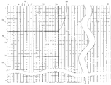
- FIG. 1 indicates how an image may be depicted as a large number of picture elements, or “pixels,” 12 arranged in a rectangular matrix of m columns and n rows.
- pixels picture elements
- FIG. 1 indicates how an image may be depicted as a large number of picture elements, or “pixels,” 12 arranged in a rectangular matrix of m columns and n rows.
- pixel array describing a picture consists of 1920 columns and 1080 rows.
- the MPEG-2 standard provides that the pixel array can be separated into a plurality of 8 ⁇ 8 pixel groups known as “blocks” 14 and 16 ⁇ 16 pixel groups 16 known as “macroblocks.”
- An imager then samples the picture, for instance by scanning the picture, thereby converting the two-dimensional picture into a one-dimensional waveform.
- the imager scans a line from left to right, retraces from right to left, and then scans the next line starting from left to right.
- the number of scan-lines effects resolution, flicker and bandwidth.
- One type of scanning is progressive scanning. Progressive scanning produces a frame in which the raster lines are sequential in time.
- Another type of scanning is interlaced scanning. Interlaced scanning produces an interlaced frame comprised of two fields which are sampled at different times. That is, interlaced scanning allow lines to be scanned alternately in two interwoven rasterized lines.
- the MPEG standard provides two Picture Structures for interlaced frames, Field Pictures and Frame Pictures. Field Pictures consist of individual fields that are divided into macroblocks and coded whereas Frame Pictures consist of interlaced fields that are divided into macroblocks and coded. Furthermore, the MPEG standard provides two macroblock DCT modes for Frame Pictures, field mode and frame
- the MPEG-2 standard further provides that the macroblocks of each picture may be encoded using either “intra-coding” or “inter-coding.”
- An intra-coded block is coded using data present only in the block itself, without reference to any other block.
- an inter-coded block is coded based on one or more reference blocks, derived from one or more blocks transmitted either previous to the block being encoded or following the block being encoded.
- Encoded data of an inter-coded block consists of difference information representing the difference between a block of the reference picture and a block of the picture being encoded.
- intra-picture In an “intra-picture” (called an “I-picture”), all the blocks are “intra-coded.”
- a predictive-coded picture, or “P-picture” uses temporally preceding pictures for reference information.
- a bi-directionally predictive-coded pictures, or “B-picture,” may obtain reference information from preceding or upcoming pictures, or both.
- the blocks in P- and B-pictures may be inter-coded or intra-coded, or both.
- Reference pictures for P- and B-pictures may be P- or I-pictures.
- Video data processed according to the MPEG-2 standard is encoded using a discrete cosine transform (DCT) process, yielding a group of transform coefficients which are then quantized and subjected to variable length coding to produce a stream of encoded digital video data.
- the MPEG-2 digital video stream thus includes the quantized and encoded DCT transform coefficients, plus motion compensation information in the form of motion vector data, as well as quantizing stage size data. Details of the process by which video image data is encoded in the MPEG-2 standard are well known to those skilled in the art and will not be described further in detail.
- FIG. 2 is a functional block diagram of a conventional MPEG-2 decoder 20 .
- an encoded digital video signal 22 is supplied to an input buffer 24 , where it is stored.
- the encoded digital video signal may include MPEG-2 data.
- the encoded digital video data representing blocks of a picture are read out from input buffer 24 and supplied to an inverse variable length coding (“IVLC”) element 26 , otherwise called a variable length decoding (“VLD”) element.
- IVLC element 26 applies inverse variable length coding, also known as variable length decoding, to the incoming digital data for each block and supplies blocks of quantized transform coefficients to an inverse quantizing (“IQ”) element 28 .
- IVLC element 26 also extracts motion vector data (“MV”) and quantizing stage size data (“SS”) from the incoming data for each block.
- MV motion vector data
- SS quantizing stage size data
- IQ element 28 dequantizes each block of quantized transform coefficients in accordance with stage size data SS from IVLC element 26 .
- IQ element 28 then supplies each resulting block of transform coefficients to an inverse discrete cosine transform (“IDCT”) element 32 .
- IDCT element 32 provides a decoded block of data that is supplied to an adder element 34 .
- adder element 34 depends on the type of picture of which the incoming block is a part. If the block is from an I-picture, it is intra-coded wherein the decoded data is complete in and of itself. Thus, element 34 supplies data from this intra-coded block directly to a frame memory 36 . If the block is from a P-picture or a B-picture, the block may be inter-coded or intra-coded. If the block is intra-coded, the decoded data is complete in and of itself. Thus, element 34 supplies data from this intra-coded block directly to a frame memory 36 .
- the incoming data represents only difference information between an image block of the picture currently being received and a particular block of a reference picture that the decoder has previously received and stored in frame memory 36 .
- Motion compensation element 30 retrieves data of the block from one or more reference pictures stored in frame memory 36 .
- Motion compensation element 30 retrieves data based on MV data.
- MV data includes vector data and other “tag” information, which may be used to specify a specific frame or picture associated with the vector data.
- the tag information may indicate a particular reference picture for the vector data, which may specify a particular reference pixel within the reference picture.
- vector data includes X, Y data specifying a position in an array.
- the reference pixel indicates where the motion compensation element 30 is to start loading the reference picture data.
- Vector data includes the position of the reference pixel based upon a particular pixel array resolution, e.g. a full resolution such as an 8 ⁇ 8 pixel array per block resolution. For instance, vector data such as (3.5,0) based on an 8 ⁇ 8 pixel array per block resolution, indicates that the motion compensation element 30 should start loading the 8 ⁇ 8 reference block at position (3.5,0).
- the value 3.5 indicates an X pixel position in between a pixel at value 3 and a pixel at value 4, and the value 0 indicates the Y pixel position at row 0 of the array.
- Motion compensation element 30 supplies the retrieved reference data to adder element 34 .
- Adder element 34 then combines the reference block data from motion compensation element 30 with the incoming difference data from IDCT element 32 to form a complete block of the picture being received, and stores it in frame memory 36 .
- the digital data for the entire picture is output for display on a display device 40 .
- conventional digital television signals are generally decoded using a conventional system as shown in FIG. 2 .
- a full resolution decoder will perform inverse DCT processing on all information received. For example, if the digital television signal was encoded using 8 ⁇ 8 pixel array per block, a full resolution decoder will perform decoding on 8 ⁇ 8 pixel array per block.
- full resolution processing is CPU-intensive, requires significant processing power, and is often unneeded when the resulting video signals are received and displayed on a device that will not display the full picture, such as a picture-in-picture screen.
- a conventional decoder decodes I-, B- and P- pictures to the same resolution. This may cause inefficient use of system resources.
- decoding of a B-picture requires both maximum memory bandwidth and maximum computational complexity.
- the use of B-pictures is not as important for image quality as I-pictures and P-pictures.
- the embodiments described herein reallocate hardware resources to obtain high quality I- and P-pictures by using the same hardware resources for these pictures as for B-pictures. For instance, some arrays of data may be processed at full resolution while other arrays of received data may be processed at lower resolutions. In particular, arrays of data associated with I- or P-pictures may be processed at full vertical resolution and half horizontal resolution, whereas arrays of data associated with B-pictures may be processed at that same resolution or lower resolutions.
- the following embodiments provide high image quality while yielding low peak memory bandwidth and computational complexity.
- the following embodiments are particularly applicable for both primary decoders in small-screen television receivers and auxiliary decoders to provide partial screen features such as split screen and picture-in-picture on large-screen television receivers.
- the input image data sizes may be for high definition (HD) image sizes (e.g., 1920 ⁇ 1080 interlaced or 1280 ⁇ 720 interlaced/progressive), standard definition (SD) image sizes (720 ⁇ 480 interlaced/progressive), or Common Intermediate Format (CIF) image sizes (360 ⁇ 240 or 252 ⁇ 288).
- HD high definition
- SD standard definition
- CIF Common Intermediate Format
- the lower resolution image size may also include the CIF image size (360 ⁇ 240 or 252 ⁇ 288) or Quarter Common Intermediate Format (QCIF) image size (176 ⁇ 244), which are common data formats for portable or mobile devices having digital image display capabilities.
- FIG. 3 is a functional diagram of a system consistent with the present invention for decoding digital image data.
- the system of FIG. 3 processes digital image data using methods described below.
- the system of FIG. 3 receives digital image data into a buffer 24 and performs inverse variable length coding and inverse quantization at elements 26 and 28 , respectively.
- the system of FIG. 3 includes an IDCT element 50 that may selectively perform IDCT processing on only a subset or sub-portion of the DCT coefficients supplied to it in order to produce a lower resolution output with a smaller group of pixels.
- IDCT element 50 performs down conversion on an 8 ⁇ 8 array of DCT coefficients by processing a 4 ⁇ 8 sub-portion of the coefficients to produce a 4 ⁇ 8 pixel array.
- the 4 ⁇ 8 array of coefficients may be chosen, for example, by using the first 4 coefficients per row in the 8 ⁇ 8 array.
- the produced 4 ⁇ 8 pixel array used in this example would correspond to full vertical resolution and half horizontal resolution.
- I-, P- and B-pictures are all decoded to produce full vertical resolution and half horizontal resolution output.
- IDCT element 50 may perform down conversion using algorithms described below.
- IDCT element 50 may, however, implement more than one algorithm during the down conversion process. For example, a process may be performed on coefficients in both the horizontal and vertical direction. This requires implementing a down conversion algorithm in the horizontal direction and in the vertical direction.
- IDCT element 50 implements a standard 4-point IDCT algorithm in the horizontal direction and a standard 8-point IDCT algorithm in the vertical direction.
- the standard 4-point IDCT and standard 8-point IDCT algorithms may be based on a normal type II one-dimensional algorithm as defined below.
- IDCT element 50 may set one or more coefficients to zero to produce a lower resolution output.
- IDCT element 50 may selectively reset coefficients x(m) to zero in order to accommodate insufficient CPU power. This reduces the amount of processing during down conversion.
- IDCT element 50 may apply an 8-point IDCT algorithm in the vertical direction in which some coefficients x(m) are set to zero if CPU power is not sufficient.
- IDCT element 50 may reset coefficients in the vertical direction to zero in order of priority, e.g., x(5), x(4), x(3) and x(2) may be set to zero.
- IDCT element 50 may reset coefficients in the vertical direction to zero in order of priority, e.g., x(7), x(6), x(5) and x(4) may be set to zero. Moreover, as coefficients are selectively set to zero, IVLC element 26 and IQ element 28 may thus ignore coefficients set to zero. This trade-off between conserving CPU power should be balanced with resulting degraded picture quality caused by setting coefficients to zero.
- IDCT element 50 supplies the decoded block of data to adder element 34 .
- IDCT element 50 outputs a 4 ⁇ 8 pixel array to adder element 34 .
- the operation of adder element 34 depends on the type of incoming block and the type of associated picture. As mentioned above, the blocks in I-pictures are all intra-coded, whereas the blocks in P- and B-pictures may be intra-coded or inter-coded. If the block is intra-coded, the decoded data is complete in and of itself. Thus, adder element 34 supplies data from this incoming block directly to display buffer 62 .
- adder element 34 also supplies the data to the reference buffer 64 for storage. Conversely, B-picture data is not supplied to reference buffer 64 because B-picture data is not used to decode subsequent pictures.
- the incoming data represents only difference information between an image block of the picture currently being received and a particular block of a reference picture that the decoder has previously received and stored in reference buffer 64 .
- the particular reference block or blocks must be supplied to the adder element 34 for use with the decoded inter-coded block.
- the particular reference picture block or blocks is specified by the motion vector data (“MV”).
- MV data is supplied to motion compensation element 60 .
- Motion compensation element 60 retrieves data of the specified block from one or more reference pictures stored in reference buffer 64 , and supplies it to adder element 34 .
- Data from motion compensation element 60 is combined with incoming decoded data to form a pixel array and the results are stored in display buffer 62 .
- P-picture data is also stored in reference buffer 64 .
- B-picture data is not supplied to reference buffer 64 because B-picture data is not used to decode subsequent pictures.
- Motion compensation element 60 uses MV data and reference information from reference buffer 64 to generate motion compensation data.
- the MV data is based upon a particular pixel array resolution.
- the resolution of the reference information obtained from reference buffer 64 may not be the same as the resolution associated with the MV data.
- the MV data from the MPEG-2 data stream is based on full size reference frames, or 8 ⁇ 8 pixel array per block, whereas the reference information in reference buffer 64 may relate to a lower resolution, e.g. 4 ⁇ 8 pixel array per block. In that case, the reference frame size in the horizontal direction would be half the full size reference frame.
- the motion compensation element 60 translates the MV data to the resolution of the data within the reference buffer.
- the motion compensation element 60 would translate the motion vector data to (3,0). Then, motion compensation element 60 would use this translated MV data to indicate the position of the reference pixel to load reference data.
- the motion compensation element 60 up-samples the reference data to supply the missing pixel reference data. Since the adder element 34 combines the data inputs, the motion compensation element 60 down-samples the motion compensation data to yield motion compensation data that has the same resolution as the decoded data from IDCT element 50 . Down-sampling supplies pixels when converting from a higher resolution pixel array to a lower resolution pixel array. For instance, in the embodiment described above, motion compensation element 60 down-samples the data to yield a 4 ⁇ 8 block to match the 4 ⁇ 8 block of decoded data from IDCT element 50 . This motion compensation operation is provided in more detail below regarding FIG. 4 .
- FIG. 4 is a flow chart of a method for providing motion compensation consistent with the present invention when the motion vector data does not correspond to existing pixel reference data.
- a motion compensation element receives a pixel array from the reference buffer. If the reference buffer stores 4 ⁇ 8 pixel arrays, the horizontal resolution is half the full vertical resolution such that every other pixel is missing from the received pixel array.
- the pixel array may be represented as, e.g., P0 M1 P2 M3 P4 M5 P6 M7 P8 M9 P10 . . . , where Pi is the existing pixel, and Mi is the missing pixel.
- the motion compensation element first determines the missing pixels at the half positions for row 0.
- the motion compensation element up-samples, or computes the missing pixels, M(i) from the existing pixels at stage 44 .
- the missing pixels may be computed with the following formula: M i+1 (9 *P i +9 *P i+2 ⁇ P i ⁇ 2 ⁇ P i+4 +8)/16.
- motion compensation element performs a standard MPEG half pixel interpolation to compute missing pixels at the quarter positions for that row at stage 46 .
- the pixels may be computed from the existing pixels and the calculated pixels at the half positions using the following formula: (M3+P4+1)/2, (P4+M5+1)/2, (M5+P6+1)/2, (P6+M7+1)/2, (M7+P8+1)/2, (P8+M9+1)/2, (M9+P10+1)/2, and (P10+M11+1)/2.
- Motion compensation element then sub-samples the pixel data to a resolution associated with the IDCT data results at stage 48 .
- every other pixel may be dropped to produce pixel data as shown below. (M3+P4+1)/2, (M5+P6+1)/2, (M7+P8+1)/2 and (M9+P10+1)/2.
- the motion compensation element supplies the motion compensation data to the adder element.
- stages 44 , 46 and 48 may be merged into a single stage because the MPEG standard half pixel interpolation and up-sample calculation can be merged into a single interpolation.
- Stage 44 computing the missing pixels, and stage 46 , performing the half pixel interpolation may be merged as indicated below. ( M i+1 +P i+2 +1)/2 ⁇ (9* P i +25 *P i+2 ⁇ P i ⁇ 2 ⁇ P i+4 +16)/32
- the merge can cut the complexity of the motion compensation, thereby reducing the amount of processing.
- buffers 62 and 64 may be sized according to the amount of data expected. Alternatively, buffers 62 and 64 may be sized to contain pixel data for an entire decoded picture including full resolution of the original image to accommodate the occasion when some arrays are processed in full resolution.
- the pixel data from display buffer 62 is supplied to a scaler element 66 which scales the pixel data stored in display buffer 62 to full display size. Scaling may be performed using any available scaling techniques that are well known to those skilled in the art. Common methods of scaling may be found in Castleman, 1996, “Processing Sampled Data” Digital Image Processing 12:253–279. The scaled pixel data is then supplied to a display element 68 .
- FIG. 5 shows an alternative system consistent with the present invention, suitable for applications in which processor resources are more limited than memory resources.
- I-picture and P-picture data may be in the reduced resolution manner (4 ⁇ 8 pixel array) described above regarding FIG. 3 .
- FIG. 5 describes an exemplary system where B-pictures may be processed in a reduced resolution manner (4 ⁇ 4 pixel array) and then up-sampled to a higher resolution (4 ⁇ 8 pixel array). Similar to FIG. 3 , the output of IQ element 28 is an 8 ⁇ 8 array of DCT coefficients.
- IDCT element 51 may receive, for example, an 8 ⁇ 8 DCT coefficient array and produce a 4 ⁇ 4 pixel array. IDCT element 51 may process a subset or sub-potion of the 8 ⁇ 8 DCT coefficients to produce the 4 ⁇ 4 pixel array. In one embodiment, IDCT element 51 receives an 8 ⁇ 8 DCT coefficient matrix and performs down conversion by processing a 4 ⁇ 8 sub-portion of the received coefficient array to produce a 4 ⁇ 4 pixel array. The 4 ⁇ 8 sub-portion may be chosen by, for example, using the first 4 coefficients per row in the 8 ⁇ 8 array. The produced 4 ⁇ 4 pixel array would yield a resolution of one-half the original resolution in both the vertical and horizontal dimensions.
- Processing a 4 ⁇ 8 array of DCT coefficients to produce a 4 ⁇ 4 pixel array allows use of a significantly less powerful IDCT element.
- the resulting 4 ⁇ 4 pixel array is then processed by an up-sample element 33 in a manner well known by those skilled in the art to produce a higher resolution pixel array such as, for example, a 4 ⁇ 8 pixel array.
- the 4 ⁇ 8 pixel array is then processed by elements 60 , 34 , 62 , 64 , 66 and 68 of the system of FIG. 5 in the same manner as described previously regarding FIG. 3 .
- IDCT element 51 receives an 8 ⁇ 8 DCT coefficient matrix and performs down conversion by processing a 4 ⁇ 8 sub-portion of the received coefficients to produce a 4 ⁇ 4 pixel array output.
- IDCT element 51 may perform down conversion using one or more algorithms. For example, as described above in FIG. 3 , a process may be performed for coefficients in both the horizontal and vertical direction.
- IDCT element 51 performs a standard 4-point IDCT algorithm, as described above, in the horizontal direction. In the vertical direction, IDCT element 51 can process an interlaced Frame Picture when macroblock DCT mode is frame using, for example, an 8-point one-dimensional reduced-IDCT algorithm. In other cases, a 4-point one-dimensional reduced-IDCT algorithm can be used in the vertical direction. The 8-point and 4-point one-dimensional algorithms are described below.
- the 8-point one-dimensional reduced-IDCT multiplies the 8 point coefficient array X(n) by a 4 ⁇ 8 matrix ‘A’ of constants to produce a pixel output, Y(i).
- constant matrix ‘A’ is defined as follows:
- a ⁇ ( m , n ) [ 4096 4756 1448 871 1567 1303 3496 2912 4096 4756 - 1448 - 871 - 1567 - 1303 - 3496 - 4511 4096 - 3297 - 1448 871 - 1567 1303 - 3496 4511 4096 - 4756 1448 - 871 1567 - 1303 3496 - 2912 ]
- the 8-point one-dimensional reduced IDCT algorithm is defined as follows:
- the last coefficients of the 8 point array X(n) are dropped to produce a 4-point array.
- a standard 4-point IDCT algorithm uses the coefficients in the vertical direction to generate pixel output. IDCT element 51 then divides the results attained by two to obtain the correct pixel values.
- FIG. 6 shows another alternative system consistent with the present invention that is suitable for applications in which both processing power and memory must be restricted.
- the system of FIG. 6 generally processes digital image data in the same manner as described above with respect to the systems of FIGS. 3 and 5 .
- DCT coefficients supplied by inverse quantization element 28 may be processed by IDCT element 51 to yield a 4 ⁇ 4 array of pixel data in the same manner as discussed above with respect to FIG. 5 .
- the 4 ⁇ 4 pixel data is not up-sampled.
- Data from the motion compensation element 63 may be processed in the same manner as described above with respect to FIG. 3 .
- the 4 ⁇ 4 array of pixel data is combined with data from motion compensation element 63 to form a 4 ⁇ 4 array of pixel data and is stored in a display buffer 62 .
- Display buffer 62 then may have a size corresponding to one-half resolution in both the vertical and horizontal dimensions.
- I- and P-pictures are processed in the reduced resolution manner described above with respect to FIG. 3 . Consequently, the reference data contained within the reference buffer 64 is comprised of 4 ⁇ 8 pixel arrays.
- B-pictures may be processed in the reduced resolution manner described above with respect to FIG. 6 . Consequently, IDCT element 51 yields 4 ⁇ 4 arrays of B-picture pixel data.
- the motion compensation element 63 retrieves 4 ⁇ 8 pixel per block reference data and performs the standard motion prediction with the motion vector data and the retrieved reference data. However, in this embodiment, motion compensation element 63 then down-samples the motion compensation data to yield a 4 ⁇ 4 block to match the 4 ⁇ 4 block of decoded B-picture data from IDCT element 51 .
- display element 68 matches the resolution of the picture output. For instance, in this example, display element 68 drops every other line of the 4 ⁇ 8 I- and P-picture data in display buffer 62 to match the 4 ⁇ 4 resolution of B-picture output. In this way, the display quality of I- and P-pictures resembles the quality of the B-pictures. Pixel data is then output from display buffer 62 and processed by scaler element 66 in both horizontal and vertical dimensions to the appropriate display size. It is then supplied to display element 68 .
- FIG. 7 is a logic flow diagram of a method consistent with the invention.
- FIG. 7 shows a method that may be used by the system of FIG. 3 .
- a block of dequantized data is received.
- the block of dequantized data is 8 ⁇ 8 in size. It is determined, at stage 102 , whether the block is from a B-picture. If not, the data is from either a P-picture or an I-picture. If the data is from a B-picture, the IDCT processes a sub-portion of the DCT coefficients, for example, a 4 ⁇ 8 sample, to obtain a 4 ⁇ 8 block of pixel data (stage 114 ).
- stage 115 It is determined, at stage 115 , whether the block is intra-coded. If the block is intra-coded, the process continues to stage 112 . If the block is not intra-coded it is inter-coded. In that case, the 4 ⁇ 8 block of pixel data is added to reference data obtained from a reference buffer (stage 116 ). The reference data may describe either a preceding or upcoming frame, or both. The resulting 4 ⁇ 8 block of pixel data is stored in an output frame buffer, or display buffer (stage 112 ). The data is then scaled to the size of the display (stage 118 ), and output for display (stage 120 ).
- the data is from an I- or P-picture.
- IDCT may be performed on a sub-portion of the coefficients, such as a 4 ⁇ 8 sub-portion (stage 104 ). If the resulting pixel data is intra-coded (stage 106 ), the block of pixel data is stored at stage 108 in a reference frame buffer. If it is determined at stage 106 that the data is not intra-coded, it is inter-coded. Thus, motion compensation is performed at stage 110 using forward reference frame data from a reference frame buffer. For both I- and P-pictures, the pixel data is then stored in a reference frame buffer (stage 108 ).
- Both the I-picture data and P-picture data are stored at stage 112 in an output frame buffer, otherwise called a display buffer.
- an output frame buffer otherwise called a display buffer.
- data is then scaled at stage 118 to appropriate display size and then provided as output for display at stage 120 .
- FIG. 8 Another method for decoding image data consistent with the present invention is shown in FIG. 8 .
- the method of FIG. 8 may be performed, for example, by the system of FIG. 5 .
- a block of dequantized data is received. It is determined at stage 202 if the block is from a B-picture. If not, the block is from an I- or P-picture. In that case, IDCT processing may be performed at stage 204 using a 4 ⁇ 8 block of DCT coefficients to obtain resulting pixel data. It is determined at stage 206 if the block is intra-coded. If so, the 4 ⁇ 8 block of pixel data is stored at stage 208 in a reference frame buffer.
- stage 206 If it is determined at stage 206 that the data is not intra-coded, it is inter-coded. Thus, motion compensation is performed at stage 210 using forward reference frame data from a reference frame buffer. For both I- and P-pictures, the pixel data is then stored in a reference frame buffer (stage 208 ). Both the I-picture data and P-picture data are stored at stage 212 in an output frame buffer, otherwise called a display buffer.
- IDCT processing may be performed to produce a 4 ⁇ 4 block of pixel data using, for example, a 4 ⁇ 4 array of DCT coefficients (stage 214 ).
- the resulting 4 ⁇ 4 block of pixel data is then up-sampled to form a 4 ⁇ 8 array of data (stage 216 ).
- stage 217 It is determined, at stage 217 , whether the block is intra-coded. If the block is an intra-coded, the process continues to stage 212 . If the block is not intra-coded, it is inter-coded. In that case, motion compensation is performed using forward, backward, or both forward and backward reference frame data obtained from a reference frame buffer (stage 218 ).
- the motion compensated data is then stored in an output frame buffer (stage 212 ).
- the pixel data in the output frame buffer is then scaled at stage 220 to appropriate display size and output for display at stage 222 .
- FIG. 9 is a logic flow diagram of another method for decoding image data consistent with the present invention.
- the method of FIG. 9 may be performed, for example, by the system of FIG. 6 .
- a decoder receives a block of dequantized data. It is determined at stage 302 if the block is from a B-picture. If not, the data is from either a P-picture or an I-picture.
- IDCT processing is performed at stage 304 to produce, for example, a 4 ⁇ 8 pixel array, using, for example, a 4 ⁇ 8 array of DCT coefficients. It is determined at stage 306 if the block is intra-coded. If so, the resulting array of pixel data is stored in a reference frame buffer at stage 308 .
- the block is not intra-coded, as determined at stage 306 , it is inter-coded. Accordingly, motion compensation is performed at stage 310 using forward reference frame data. The motion compensated data is then stored at 308 in a reference frame buffer. The I-picture data and P-picture data are stored at stage 312 in an output frame buffer, otherwise called a display buffer.
- IDCT processing is performed at stage 314 to produce a 4 ⁇ 4 array of pixel data using, for example, a 4 ⁇ 4 array of DCT coefficients. It is determined, at stage 315 , whether the block is intra-coded. If the block is intra-coded, the process continues to stage 318 . If the block is not intra-coded it is inter-coded. In that case, motion compensation is then performed using data from forward and backward reference frame buffers at stage 316 . The 4 ⁇ 4 pixel data is then stored in an output frame buffer at stage 318 .
- output data for complete I- and P-pictures is then scaled in the horizontal dimension to appropriate display size at stage 320 and output for display at stage 322 .
- I- and P-pictures are scaled to the same resolution as B-picture output before they are scaled to the appropriate display size.
- pixel data, stored as 4 ⁇ 4 blocks, in an output frame buffer is then scaled at stage 324 in both the horizontal and vertical dimensions to appropriate display size and output for display at stage 322 .
- FIG. 10 is a block diagram of a digital television receiver 490 consistent with the present invention.
- An antenna 500 or a cable connection provides an RF television broadcast signal to an RF tuner 502 .
- Tuner 502 selects a desired broadcast channel, as indicated by the viewer, and supplies the selected RF signals to a demodulator 504 .
- Demodulator 504 extracts digital encoded video signals from the radio frequency (RF) signals and supplies the encoded video signals in an ITU-R BT.601/656 format to a multimedia processor 506 .
- Processor 506 is connected to a memory element 508 which preferably comprises a static dynamic random access memory (SDRAM).
- SDRAM static dynamic random access memory
- Processor 506 provides decoded digital video signals to a flexible video scaler 509 which in turn provides input to an national television standards committee (NTSC) encoder 510 .
- Encoder 510 converts the decoded video signals to standard NTSC format analog signals for display on a television monitor 512 .
- Receiver 490 is controlled by a user interface component 514 which may include, for example, an infrared handheld transmitter and an infrared receiver to permit a user to control receiver 490 .
- functions of tuner 502 , demodulator 504 , processor 506 , and encoder 510 are performed by a MAP-CA processor commercially available from Equator Technologies, Inc. of Campbell, Calif., which executes the methods of FIGS. 7 , 8 , and 9 from instructions stored in a memory thereof.
- IDCT and motion compensation processing techniques are implemented for the MPEG-2 data format, but may be implemented for other data formats.
- the above algorithms for IDCT and motion compensation processing may be implemented with data formats such as, for example, the H261 H263, MPEG-1, and MPEG-4 having half pixel motion vectors formats.
- the above IDCT algorithms may be implemented for the data formats in the JPEG or DV data formats in which motion compensation processing is not necessary.
- similar IDCT processing techniques may be implemented on MPEG-4 data formats having quarter pixel motion vectors.
- aspects of the present invention are described as being stored in memory, one skilled in the art will appreciate that these aspects can also be stored on or read from other types of computer-readable media, such as secondary storage devices, like hard disks, floppy disks, or CD-ROMs; a carrier wave from the Internet; or other forms of RAM or ROM.
- the method of the present invention may conveniently be implemented in program modules that are based upon the flow charts in FIGS. 7–9 . No particular programming language has been indicated for carrying out the various procedures described above because it is considered that the operations, stages and procedures described above and illustrated in the accompanying drawings are sufficiently disclosed to permit one of ordinary skill in the art to practice the instant invention.
Abstract
Description
wherein y(i) is the pixel output, x(m) is an input coefficient, and N is either 4 or 8 for the 4-point and 8-point IDCT algorithms, respectively.
M i+1 (9*P i+9*P i+2 −P i−2 −P i+4+8)/16.
(M3+P4+1)/2, (P4+M5+1)/2, (M5+P6+1)/2, (P6+M7+1)/2, (M7+P8+1)/2, (P8+M9+1)/2, (M9+P10+1)/2, and (P10+M11+1)/2.
(M3+P4+1)/2, (M5+P6+1)/2, (M7+P8+1)/2 and (M9+P10+1)/2.
(M i+1 +P i+2+1)/2≈(9*P i+25*P i+2 −P i−2 −P i+4+16)/32
Although the rounding of the left side is slightly different from the right side, the merge can cut the complexity of the motion compensation, thereby reducing the amount of processing.
Thus, the 8-point one-dimensional reduced IDCT algorithm is defined as follows:
Claims (26)
Priority Applications (3)
| Application Number | Priority Date | Filing Date | Title |
|---|---|---|---|
| US10/014,689 US7227895B1 (en) | 2000-12-12 | 2001-12-11 | System and method for generating decoded digital video image data |
| US11/787,808 US8045622B2 (en) | 2000-12-12 | 2007-04-17 | System and method for generating decoded digital video image data |
| US13/217,806 US20110310972A1 (en) | 2000-12-12 | 2011-08-25 | System and method for generating decoded digital video image data |
Applications Claiming Priority (2)
| Application Number | Priority Date | Filing Date | Title |
|---|---|---|---|
| US25457200P | 2000-12-12 | 2000-12-12 | |
| US10/014,689 US7227895B1 (en) | 2000-12-12 | 2001-12-11 | System and method for generating decoded digital video image data |
Related Child Applications (1)
| Application Number | Title | Priority Date | Filing Date |
|---|---|---|---|
| US11/787,808 Continuation US8045622B2 (en) | 2000-12-12 | 2007-04-17 | System and method for generating decoded digital video image data |
Publications (1)
| Publication Number | Publication Date |
|---|---|
| US7227895B1 true US7227895B1 (en) | 2007-06-05 |
Family
ID=38090216
Family Applications (3)
| Application Number | Title | Priority Date | Filing Date |
|---|---|---|---|
| US10/014,689 Active 2025-05-24 US7227895B1 (en) | 2000-12-12 | 2001-12-11 | System and method for generating decoded digital video image data |
| US11/787,808 Expired - Fee Related US8045622B2 (en) | 2000-12-12 | 2007-04-17 | System and method for generating decoded digital video image data |
| US13/217,806 Abandoned US20110310972A1 (en) | 2000-12-12 | 2011-08-25 | System and method for generating decoded digital video image data |
Family Applications After (2)
| Application Number | Title | Priority Date | Filing Date |
|---|---|---|---|
| US11/787,808 Expired - Fee Related US8045622B2 (en) | 2000-12-12 | 2007-04-17 | System and method for generating decoded digital video image data |
| US13/217,806 Abandoned US20110310972A1 (en) | 2000-12-12 | 2011-08-25 | System and method for generating decoded digital video image data |
Country Status (1)
| Country | Link |
|---|---|
| US (3) | US7227895B1 (en) |
Cited By (10)
| Publication number | Priority date | Publication date | Assignee | Title |
|---|---|---|---|---|
| US20050083218A1 (en) * | 2003-09-07 | 2005-04-21 | Microsoft Corporation | Signaling for field ordering and field/frame display repetition |
| US20050100093A1 (en) * | 2003-09-07 | 2005-05-12 | Microsoft Corporation | Signaling field type information |
| US20050152457A1 (en) * | 2003-09-07 | 2005-07-14 | Microsoft Corporation | Signaling and repeat padding for skip frames |
| US20090034859A1 (en) * | 2006-03-22 | 2009-02-05 | Samsung Electronics Co., Ltd. | Image display apparatus and method for correction chroma wrinkle |
| US20090296815A1 (en) * | 2008-05-30 | 2009-12-03 | King Ngi Ngan | Method and apparatus of de-interlacing video |
| US20120082208A1 (en) * | 2010-09-30 | 2012-04-05 | Alcatel-Lucent Usa Inc. | Method and apparatus for arbitrary resolution video coding using compressive sampling measurements |
| US20120195376A1 (en) * | 2011-01-31 | 2012-08-02 | Apple Inc. | Display quality in a variable resolution video coder/decoder system |
| US9563806B2 (en) | 2013-12-20 | 2017-02-07 | Alcatel Lucent | Methods and apparatuses for detecting anomalies using transform based compressed sensing matrices |
| US9600899B2 (en) | 2013-12-20 | 2017-03-21 | Alcatel Lucent | Methods and apparatuses for detecting anomalies in the compressed sensing domain |
| US9894324B2 (en) | 2014-07-15 | 2018-02-13 | Alcatel-Lucent Usa Inc. | Method and system for modifying compressive sensing block sizes for video monitoring using distance information |
Families Citing this family (3)
| Publication number | Priority date | Publication date | Assignee | Title |
|---|---|---|---|---|
| US20110210975A1 (en) * | 2010-02-26 | 2011-09-01 | Xgi Technology, Inc. | Multi-screen signal processing device and multi-screen system |
| US9762899B2 (en) * | 2011-10-04 | 2017-09-12 | Texas Instruments Incorporated | Virtual memory access bandwidth verification (VMBV) in video coding |
| TWI597968B (en) * | 2012-12-21 | 2017-09-01 | 杜比實驗室特許公司 | High precision up-sampling in scalable coding of high bit-depth video |
Citations (14)
| Publication number | Priority date | Publication date | Assignee | Title |
|---|---|---|---|---|
| US5351083A (en) | 1991-10-17 | 1994-09-27 | Sony Corporation | Picture encoding and/or decoding system |
| US5457675A (en) | 1993-01-18 | 1995-10-10 | Sony Corporation | Video image updating and reproducing device with image selecting key input means |
| US5461423A (en) | 1992-05-29 | 1995-10-24 | Sony Corporation | Apparatus for generating a motion vector with half-pixel precision for use in compressing a digital motion picture signal |
| US5504530A (en) | 1992-06-25 | 1996-04-02 | Sony Corporation | Apparatus and method for coding and decoding image signals |
| US5563714A (en) | 1994-04-21 | 1996-10-08 | Sony Corporation | Digital signal processing apparatus for recording and reproducing time-base compressed digital image data in an image transmission system |
| US5563660A (en) | 1992-11-30 | 1996-10-08 | Sony Corporation | Decoder for a compressed digital video signal using a common memory for decoding and 2/3 pull-down conversion |
| US5635985A (en) | 1994-10-11 | 1997-06-03 | Hitachi America, Ltd. | Low cost joint HD/SD television decoder methods and apparatus |
| US5818533A (en) | 1996-08-08 | 1998-10-06 | Lsi Logic Corporation | Method and apparatus for decoding B frames in video codecs with minimal memory |
| US5987074A (en) | 1996-05-02 | 1999-11-16 | Sony Corporation | Digital communication demodulator, digital communication demodulation method and digital demodulation circuit |
| US6141457A (en) * | 1997-09-12 | 2000-10-31 | Samsung Electronics Co., Ltd. | Method and apparatus for processing a high definition image to provide a relatively lower definition image using both discrete cosine transforms and wavelet transforms |
| US6175592B1 (en) * | 1997-03-12 | 2001-01-16 | Matsushita Electric Industrial Co., Ltd. | Frequency domain filtering for down conversion of a DCT encoded picture |
| US6184935B1 (en) * | 1997-03-12 | 2001-02-06 | Matsushita Electric Industrial, Co. Ltd. | Upsampling filter and half-pixel generator for an HDTV downconversion system |
| US6243421B1 (en) * | 1996-03-04 | 2001-06-05 | Kokusai Denshin Denwa Kabushiki Kaisha | Apparatus for decoding coded video data with reduced memory size |
| US6266374B1 (en) * | 1994-10-28 | 2001-07-24 | Lg Electronics Inc. | Low level digital video decoder for HDTV having backward compatibility |
Family Cites Families (1)
| Publication number | Priority date | Publication date | Assignee | Title |
|---|---|---|---|---|
| US6310919B1 (en) * | 1998-05-07 | 2001-10-30 | Sarnoff Corporation | Method and apparatus for adaptively scaling motion vector information in an information stream decoder |
-
2001
- 2001-12-11 US US10/014,689 patent/US7227895B1/en active Active
-
2007
- 2007-04-17 US US11/787,808 patent/US8045622B2/en not_active Expired - Fee Related
-
2011
- 2011-08-25 US US13/217,806 patent/US20110310972A1/en not_active Abandoned
Patent Citations (15)
| Publication number | Priority date | Publication date | Assignee | Title |
|---|---|---|---|---|
| US5351083A (en) | 1991-10-17 | 1994-09-27 | Sony Corporation | Picture encoding and/or decoding system |
| US5461423A (en) | 1992-05-29 | 1995-10-24 | Sony Corporation | Apparatus for generating a motion vector with half-pixel precision for use in compressing a digital motion picture signal |
| US5504530A (en) | 1992-06-25 | 1996-04-02 | Sony Corporation | Apparatus and method for coding and decoding image signals |
| US5563660A (en) | 1992-11-30 | 1996-10-08 | Sony Corporation | Decoder for a compressed digital video signal using a common memory for decoding and 2/3 pull-down conversion |
| US5457675A (en) | 1993-01-18 | 1995-10-10 | Sony Corporation | Video image updating and reproducing device with image selecting key input means |
| US5563714A (en) | 1994-04-21 | 1996-10-08 | Sony Corporation | Digital signal processing apparatus for recording and reproducing time-base compressed digital image data in an image transmission system |
| US5635985A (en) | 1994-10-11 | 1997-06-03 | Hitachi America, Ltd. | Low cost joint HD/SD television decoder methods and apparatus |
| US6061402A (en) * | 1994-10-11 | 2000-05-09 | Hitachi America, Ltd. | Methods and apparatus for efficiently decoding bi-directionally coded image data |
| US6266374B1 (en) * | 1994-10-28 | 2001-07-24 | Lg Electronics Inc. | Low level digital video decoder for HDTV having backward compatibility |
| US6243421B1 (en) * | 1996-03-04 | 2001-06-05 | Kokusai Denshin Denwa Kabushiki Kaisha | Apparatus for decoding coded video data with reduced memory size |
| US5987074A (en) | 1996-05-02 | 1999-11-16 | Sony Corporation | Digital communication demodulator, digital communication demodulation method and digital demodulation circuit |
| US5818533A (en) | 1996-08-08 | 1998-10-06 | Lsi Logic Corporation | Method and apparatus for decoding B frames in video codecs with minimal memory |
| US6175592B1 (en) * | 1997-03-12 | 2001-01-16 | Matsushita Electric Industrial Co., Ltd. | Frequency domain filtering for down conversion of a DCT encoded picture |
| US6184935B1 (en) * | 1997-03-12 | 2001-02-06 | Matsushita Electric Industrial, Co. Ltd. | Upsampling filter and half-pixel generator for an HDTV downconversion system |
| US6141457A (en) * | 1997-09-12 | 2000-10-31 | Samsung Electronics Co., Ltd. | Method and apparatus for processing a high definition image to provide a relatively lower definition image using both discrete cosine transforms and wavelet transforms |
Non-Patent Citations (7)
| Title |
|---|
| Chris Basoglu, Ph.D., et al., The MAP-CA VLIW-based Media Processor From Equator Technologies Inc. and Hitachi Ltd., Hitachi America Sys. Dev. Lab., undated, 13 pages. |
| Chris Basoglu, Ph.D., et al., The MAP-CA VLIW-based Media Processor From Equator Technologies Inc. Hitachi, Ltd., Media Accelerated Processor for Consumer Appliances MAPCA2000 CA(TM) Data Sheet, Feb. 5, 2000, 2 pages. |
| Chris Runquist, "Hitachi and the Equator Off the Map", Post Industry.com, Mar. 22, 2000, 3 pages. |
| Equator Technologies and Hitachi Ltd. Introduce MPA-CA Processor, Jun. 10, 2000, 5 pages, available at www.hdtvbuyer....hitachiintroducemap<SUB>-</SUB>caprocessor.html. |
| Equator Technologies, Inc. and Hitachi Ltd. Introduce MAP-CA(TM) Processor, News Release, Mar. 7, 2000, 7 pages. |
| Kenneth R. Castleman, "Digital Image Processing", Chapter 12: Processing Sampled Data, pp. 253-279 (Prentice Hall 1996). |
| Wenwu Zhu, et al., "A Fast and Memory Efficient Algorithm for Down-Conversion of an HDTV Bitstream to an SDTV Signal," IEEE Transactions on Consumer Electronics, vol. 45, No. 1, Feb. 1999, pp. 57-61. |
Cited By (17)
| Publication number | Priority date | Publication date | Assignee | Title |
|---|---|---|---|---|
| US20050100093A1 (en) * | 2003-09-07 | 2005-05-12 | Microsoft Corporation | Signaling field type information |
| US20050152457A1 (en) * | 2003-09-07 | 2005-07-14 | Microsoft Corporation | Signaling and repeat padding for skip frames |
| US7961786B2 (en) * | 2003-09-07 | 2011-06-14 | Microsoft Corporation | Signaling field type information |
| US8107531B2 (en) | 2003-09-07 | 2012-01-31 | Microsoft Corporation | Signaling and repeat padding for skip frames |
| US8116380B2 (en) | 2003-09-07 | 2012-02-14 | Microsoft Corporation | Signaling for field ordering and field/frame display repetition |
| US20050083218A1 (en) * | 2003-09-07 | 2005-04-21 | Microsoft Corporation | Signaling for field ordering and field/frame display repetition |
| US8218896B2 (en) * | 2006-03-22 | 2012-07-10 | Samsung Electronics Co., Ltd. | Image display apparatus and method for correction chroma wrinkle |
| US20090034859A1 (en) * | 2006-03-22 | 2009-02-05 | Samsung Electronics Co., Ltd. | Image display apparatus and method for correction chroma wrinkle |
| US20090296815A1 (en) * | 2008-05-30 | 2009-12-03 | King Ngi Ngan | Method and apparatus of de-interlacing video |
| US8165211B2 (en) * | 2008-05-30 | 2012-04-24 | Hong Kong Applied Science and Technology Research Institute Company Limited | Method and apparatus of de-interlacing video |
| US20120082208A1 (en) * | 2010-09-30 | 2012-04-05 | Alcatel-Lucent Usa Inc. | Method and apparatus for arbitrary resolution video coding using compressive sampling measurements |
| US9634690B2 (en) * | 2010-09-30 | 2017-04-25 | Alcatel Lucent | Method and apparatus for arbitrary resolution video coding using compressive sampling measurements |
| US20120195376A1 (en) * | 2011-01-31 | 2012-08-02 | Apple Inc. | Display quality in a variable resolution video coder/decoder system |
| US9602819B2 (en) * | 2011-01-31 | 2017-03-21 | Apple Inc. | Display quality in a variable resolution video coder/decoder system |
| US9563806B2 (en) | 2013-12-20 | 2017-02-07 | Alcatel Lucent | Methods and apparatuses for detecting anomalies using transform based compressed sensing matrices |
| US9600899B2 (en) | 2013-12-20 | 2017-03-21 | Alcatel Lucent | Methods and apparatuses for detecting anomalies in the compressed sensing domain |
| US9894324B2 (en) | 2014-07-15 | 2018-02-13 | Alcatel-Lucent Usa Inc. | Method and system for modifying compressive sensing block sizes for video monitoring using distance information |
Also Published As
| Publication number | Publication date |
|---|---|
| US8045622B2 (en) | 2011-10-25 |
| US20070189395A1 (en) | 2007-08-16 |
| US20110310972A1 (en) | 2011-12-22 |
Similar Documents
| Publication | Publication Date | Title |
|---|---|---|
| US8045622B2 (en) | System and method for generating decoded digital video image data | |
| US7016419B2 (en) | Systems for MPEG subsample decoding | |
| US6385248B1 (en) | Methods and apparatus for processing luminance and chrominance image data | |
| US7471834B2 (en) | Rapid production of reduced-size images from compressed video streams | |
| US6823014B2 (en) | Video decoder with down conversion function and method for decoding video signal | |
| JP4344472B2 (en) | Allocating computational resources to information stream decoder | |
| US6104753A (en) | Device and method for decoding HDTV video | |
| US7088775B2 (en) | Apparatus and method for converting image data | |
| US6301304B1 (en) | Architecture and method for inverse quantization of discrete cosine transform coefficients in MPEG decoders | |
| US7079692B2 (en) | Reduced complexity video decoding by reducing the IDCT computation in B-frames | |
| US6665343B1 (en) | Methods and arrangements for a converting a high definition image to a lower definition image using wavelet transforms | |
| US6122321A (en) | Methods and apparatus for reducing the complexity of inverse quantization operations | |
| JP2002517109A5 (en) | ||
| US6590938B1 (en) | DCT domain conversion of a higher definition signal to lower definition signal | |
| US6993076B1 (en) | Apparatus and method for deriving an enhanced decoded reduced-resolution video signal from a coded high-definition video signal | |
| US6148032A (en) | Methods and apparatus for reducing the cost of video decoders | |
| US20010016010A1 (en) | Apparatus for receiving digital moving picture | |
| US20080159388A1 (en) | Method for generating reduced image of original image comprising blocks encoded by intra prediction and image apparatus thereof | |
| US7180948B2 (en) | Image decoder and image decoding method having a frame mode basis and a field mode basis | |
| US7627038B2 (en) | Methods and systems for compressing a video stream with minimal loss after subsampled decoding | |
| KR20030005198A (en) | Frame-type dependent reduced complexity video decoding | |
| JP2006054760A (en) | Image processor and image processing method | |
| JP2003143603A (en) | Image decoding apparatus |
Legal Events
| Date | Code | Title | Description |
|---|---|---|---|
| AS | Assignment |
Owner name: SONY ELECTRONICS, INC., NEW JERSEY Free format text: ASSIGNMENT OF ASSIGNORS INTEREST;ASSIGNORS:WANG, JASON NAXIN;TSUKAGOSHI, IKUO;REEL/FRAME:012382/0463 Effective date: 20011210 Owner name: SONY CORPORATION, JAPAN Free format text: ASSIGNMENT OF ASSIGNORS INTEREST;ASSIGNORS:WANG, JASON NAXIN;TSUKAGOSHI, IKUO;REEL/FRAME:012382/0463 Effective date: 20011210 |
|
| STCF | Information on status: patent grant |
Free format text: PATENTED CASE |
|
| FPAY | Fee payment |
Year of fee payment: 4 |
|
| FPAY | Fee payment |
Year of fee payment: 8 |
|
| AS | Assignment |
Owner name: SONY CORPORATION, JAPAN Free format text: ASSIGNMENT OF ASSIGNORS INTEREST;ASSIGNOR:SONY ELECTRONICS INC.;REEL/FRAME:036330/0420 Effective date: 20150731 |
|
| MAFP | Maintenance fee payment |
Free format text: PAYMENT OF MAINTENANCE FEE, 12TH YEAR, LARGE ENTITY (ORIGINAL EVENT CODE: M1553); ENTITY STATUS OF PATENT OWNER: LARGE ENTITY Year of fee payment: 12 |
|
| AS | Assignment |
Owner name: SATURN LICENSING LLC, NEW YORK Free format text: ASSIGNMENT OF ASSIGNORS INTEREST;ASSIGNOR:SONY CORPORATION;REEL/FRAME:048974/0222 Effective date: 20190108 |