US7222946B2 - Ink jet head and droplet ejection device having same mounted thereon - Google Patents
Ink jet head and droplet ejection device having same mounted thereon Download PDFInfo
- Publication number
- US7222946B2 US7222946B2 US10/824,588 US82458804A US7222946B2 US 7222946 B2 US7222946 B2 US 7222946B2 US 82458804 A US82458804 A US 82458804A US 7222946 B2 US7222946 B2 US 7222946B2
- Authority
- US
- United States
- Prior art keywords
- ink
- ink jet
- jet head
- piezoelectric element
- plate
- Prior art date
- Legal status (The legal status is an assumption and is not a legal conclusion. Google has not performed a legal analysis and makes no representation as to the accuracy of the status listed.)
- Expired - Fee Related, expires
Links
Images


Classifications
-
- B—PERFORMING OPERATIONS; TRANSPORTING
- B41—PRINTING; LINING MACHINES; TYPEWRITERS; STAMPS
- B41J—TYPEWRITERS; SELECTIVE PRINTING MECHANISMS, i.e. MECHANISMS PRINTING OTHERWISE THAN FROM A FORME; CORRECTION OF TYPOGRAPHICAL ERRORS
- B41J2/00—Typewriters or selective printing mechanisms characterised by the printing or marking process for which they are designed
- B41J2/005—Typewriters or selective printing mechanisms characterised by the printing or marking process for which they are designed characterised by bringing liquid or particles selectively into contact with a printing material
- B41J2/01—Ink jet
- B41J2/135—Nozzles
- B41J2/14—Structure thereof only for on-demand ink jet heads
- B41J2/14201—Structure of print heads with piezoelectric elements
- B41J2/14274—Structure of print heads with piezoelectric elements of stacked structure type, deformed by compression/extension and disposed on a diaphragm
Definitions
- the present invention relates to an ink jet head which ejects an ink droplet to perform recording and a droplet ejection device having the ink jet head mounted thereon.
- An ink jet head is normally arranged such that a driving unit such as piezoelectric element and heating resistor is driven to pressurize an ink which has been introduced into a pressurizing chamber through an ink inlet so that the ink is ejected through an orifice.
- a driving unit such as piezoelectric element and heating resistor
- ink jet head has not only been used in printing on paper but has also reached industrial use as constant amount droplet ejection device, including the production of wiring pattern and color filter for liquid crystal.
- These uses involve the use of aqueous ink as well as various liquids such as oil-based ink, solvent, strong acid and strong alkali. Therefore, the ink jet head is required to have chemical resistance.
- the recent tendency is more ink jet heads to have a higher density for ejection of minute droplet.
- a technique of efficiently ejecting droplets from such a small ink chamber has been desired.
- a thermal ink jet system is advantageous taking into account the configuration.
- this system requires that only an aqueous ink be used as a solution to be ejected and thus cannot be put to the aforementioned industrial uses.
- a drop-on-demand piezoelectric element type ink jet head which allows deformation of a piezoelectric element to apply external pressure change to an ink chamber from outside the wall thereof so that a droplet is ejected is advantageous in that there are a wide variety of solutions which can be ejected but is disadvantageous in that pressure change can difficultly be given efficiently to the ink chamber, if it is small.
- the aforementioned related art technique involves the deflection of the piezoelectric element and thus is disadvantageous in that when the area of the piezoelectric element decreases with the enhancement of the density of the ink chamber, the resulting lack of deflection restricts the driving conditions for ejection of droplets and hence the range of the weight of droplet to be ejected.
- ink viscosity the deflection of the piezoelectric element with respect to a high viscosity solution is inhibited because the piezoelectric element itself is not supported on a structure.
- this technique normally can difficultly perform ejection of a solution having a viscosity of 5 mPa ⁇ s or more.
- the vibrator takes no part in the response of the ink flow path because the piezoelectric element is mechanically connected to a structure other than the ink pressurizing chamber.
- the vibration plate of the ink pressurizing chamber is fixed to another structure with the longitudinal vibration mode piezoelectric element. In this arrangement, the acoustic capacity of the ink pressurizing chamber is so small that the response of the ink flow path to external input from the longitudinal vibration mode piezoelectric element is high.
- the piezoelectric element is mechanically connected to a structure, the deformation of the piezoelectric element can be efficiently transferred to a high viscosity solution as well. Accordingly, the range of viscosity of solution to which this mode can apply is wide.
- an aim of the invention is to provide an ink jet head having a high reliability which allows efficient deformation of vibration plate even if it has a high density and use of a wide variety of inks and a droplet ejection device comprising same.
- the invention provides an ink jet head comprising a chamber plate having a plurality of pressuring chambers formed therein for storing an ink, a vibrating plate bonded to the chamber plate, a housing having an ink flow path through which an ink is supplied into the pressuring chambers, an orifice through which an ink is ejected from the pressuring chambers and a longitudinal vibration mode piezoelectric element for generating pressure under which an ink droplet is ejected through the orifice, wherein the thickness of the vibration plate is from 5 ⁇ m to 10 ⁇ m.
- the vibration of the longitudinal vibration mode piezoelectric element can be efficiently transferred to the ink chamber.
- the ink jet head of the invention is also characterized in that the ratio of the thickness of the vibration plate to the width of the pressurizing chamber is 0.03 or less. In this arrangement, a small ink chamber capable of efficiently ejecting minute droplets can be designed.
- the ink jet head of the invention is further characterized in that a solution having a viscosity of from 5 to 25 mPa ⁇ s is ejected.
- a solution having a viscosity of from 5 to 25 mPa ⁇ s is ejected.
- various kinds of solutions can be ejected.
- a still other characteristic of the invention is that an ink jet type droplet ejection device comprising the above arranged ink jet head disposed opposed to an ejection substrate and having a mechanism for moving the ink jet head or the ejection substrate is realized.
- FIG. 1 is a sectional view of an ink jet print head which is an example of the invention
- FIG. 2 is a sectional view taken on the line A-A of FIG. 1 ;
- FIG. 3 is a diagram illustrating the relationship between the thickness of the vibration plate and height of the pressurizing chamber and the deformation of the pressurizing chamber;
- FIGS. 4 a - 4 d are diagrams illustrating a process for the preparation of a vibration plate for use in the ink jet print head of the invention
- FIG. 5 is a diagram illustrating the deformation of the pressurizing chamber developed when the ratio of the thickness of the vibration plate to the width of the pressurizing chamber changes.
- FIG. 6 is a perspective view illustrating the outline of a droplet ejection device having an ink jet head of the invention mounted thereon.
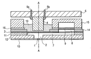
- FIG. 1 is a sectional view illustrating an example of the configuration of the nozzle portion of the ink jet head according to the invention.
- the reference numeral 1 indicates an orifice
- the reference numeral 2 indicates a pressurizing chamber
- the reference numeral 3 indicates a vibration plate
- the reference numeral 4 indicates a piezoelectric element
- the reference numerals 5 a and 5 b each indicate a signal input terminal
- the reference numeral 6 indicates a piezoelectric element fixing plate
- reference numeral 7 indicates a restrictor connecting between a common ink feed channel 8 and the pressurizing chamber 2 for controlling the flow of ink into the pressurizing chamber 2
- the reference numeral 9 indicates a filter
- the reference numeral 10 indicates an elastic adhesive such as silicon adhesive connecting between the vibration plate 3 and the piezoelectric element 4
- the reference numeral 11 indicates a restrictor plate forming the restrictor 7
- the reference numeral 12 indicates a pressurizing chamber plate forming the pressurizing chamber 2
- the reference numeral 13
- the vibration plate 3 , the restrictor plate 11 , the pressurizing chamber plate 12 and the supporting plate 14 each are made of, e.g., stainless steel.
- the orifice plate 13 is made of nickel or stainless steel.
- the piezoelectric element fixing plate 6 is made of an insulating material such as ceramics and polyimide. The ink flows downstream through the filter 9 in the common ink feed channel 8 , the restrictor 7 , the pressurizing chamber 2 and then the orifice 1 .
- the piezoelectric element 4 expands or contracts when a potential difference is applied across the signal input terminals 5 a and 5 b and returns to original state when no potential difference is applied across the signal input terminals 5 a and 5 b .
- the deformation of the piezoelectric element 4 causes the ink in the pressurizing chamber 2 to be pressurized and ejected through the orifice 1 .
- FIG. 2 is a sectional view taken along the line A-A of FIG. 1 .
- the ink jet head of the invention comprises pressurizing chambers 2 , orifices 1 and piezoelectric elements 4 each disposed at an equal interval.
- the piezoelectric element 4 contracts and the vibration plate 3 is pulled upward as viewed on the drawing (in the direction indicated by the arrow A).
- the vibration plate is deformed using a deflection mode piezoelectric element as represented by bimetal system, the effect on the adjacent ink chambers is little because the individual piezoelectric elements are separated from each other.
- the effect of deforming the ink chamber is great because the individual piezoelectric elements are connected to each other with the piezoelectric element fixing plate 6 .
- the individual piezoelectric elements are connected to each other with the piezoelectric element fixing plate 6 , vibration is transferred between the piezoelectric elements. Accordingly, the vibration plate which actually vibrates due to the deformation of the deflection mode piezoelectric element extends over the range of W as shown in FIG. 2 .
- the deformation of the line of pressurizing chambers depends not only on the thickness T of the vibration plate 3 but also on the height H of the pressurizing chamber 2 .
- FIG. 3 illustrates the results of studies of the effect of the thickness of the vibration plate 3 and the height of the pressurizing chamber 2 on the deformation of the pressurizing chamber 2 when the width of the pressurizing chamber 2 is constant.
- the deformation of the line of pressurizing chambers can be reduced by changing the height of the pressurizing chamber. However, when the height of the pressurizing chamber is changed, the volume of the pressurizing chamber is changed as well, causing the change of the weight of ink droplet to be ejected.
- the thickness T of the vibration plate 3 at which the ejection properties cannot be affected, i.e., the deformation of the pressurizing chamber is 15% or less is preferably 10 ⁇ m or less.
- the viscosity of the solution to be ejected was 10 mPa ⁇ s.
- the viscosity of the solution to be ejected was 25 mPa ⁇ s at maximum, the relationship between the thickness of the vibration plate and the height of the pressurizing chamber affecting the deformation of the pressurizing chamber remained the same.
- the vibration plate 3 is mostly made of a metal or resin. Taking into account corrosion resistance or precision of ink jet head assembly, the vibration plate 3 is preferably made of a metal.
- FIGS. 4 a - 4 d a process for the preparation of a vibration plate made of stainless steel is shown in FIGS. 4 a - 4 d.
- a thin stainless steel plate 17 having a predetermined thickness is prepared by rolling (step a).
- a resist 18 is patternwise spread over the plate 17 (step b).
- the plate 17 is wet-etched with an enchant such as ferric chloride to make a through-hole 19 (step c).
- the entire plate 17 is etched with a nitric acid solution having a concentration of from 1% to 5% for a short period of time (step d).
- the thickness of the vibration plate 3 needs to be at least 5 ⁇ m because it is likely that minute holes such as pinhole can be generated during etching with nitric acid at the step d.
- the thickness of the vibration plate 3 is preferably from 5 ⁇ m to 10 ⁇ m. While the present example has been described with reference to the case where the vibration plate 3 is made of stainless steel, the material of the vibration plate 3 is not limited so far as it is a metal. Referring to production method, electroforming, press-cutting or laser machining may be employed.
- FIG. 5 illustrates the relationship between the ratio of the thickness T of the vibration plate to the width W of the pressurizing chamber and the deformation of the line of pressurizing chambers in the case where the vibration plate is made of stainless steel.
- T/W ratio needs to be 0.03 or less to keep the deformation of the line of pressurizing chambers within a range giving no effect on the ejection properties, i.e., 15% or less.
- good properties can be maintained by selecting the optimum thickness of the vibration plate.
- a head base 31 is disposed on the top of a housing 30 .
- a head set 32 comprising one or a plurality of print heads mounted thereon is provided on the head base 31 .
- a solution to be ejected is supplied into the head set 32 through an ejection solution feed pipe 34 .
- An ejection substrate base 33 is provided opposed to the orifice 1 of the nozzle of the head set 32 ( FIG. 1 ).
- a droplet ejection substrate 35 is provided on the ejection substrate base 33 .
- the head set 32 is arranged to move in the direction X shown.
- the droplet ejection device is also arranged such that the ejection substrate base 33 can move in the direction Y. In this arrangement, an arbitrary pattern can be formed on the droplet ejection substrate 35 .
- the ink jet head according to the invention comprises a vibration plate having a thickness of from 5 ⁇ m to 10 ⁇ m, making it possible to efficiently transfer the vibration of the piezoelectric element to the ink chamber.
- a high performance ink jet head having a high ejection efficiency can be realized.
- the corrosion resistance of the ink jet head with respect to various kinds of inks can be enhanced. Further, efficient ink ejection can be realized.
Landscapes
- Particle Formation And Scattering Control In Inkjet Printers (AREA)
Abstract
Description
Claims (17)
Applications Claiming Priority (4)
| Application Number | Priority Date | Filing Date | Title |
|---|---|---|---|
| JPP.2003-114106 | 2003-04-18 | ||
| JP2003114106 | 2003-04-18 | ||
| JPP.2004-043257 | 2004-02-19 | ||
| JP2004043257A JP2004330772A (en) | 2003-04-18 | 2004-02-19 | Ink jet head and liquid droplet injection device equipped with it |
Publications (2)
| Publication Number | Publication Date |
|---|---|
| US20040207696A1 US20040207696A1 (en) | 2004-10-21 |
| US7222946B2 true US7222946B2 (en) | 2007-05-29 |
Family
ID=33161566
Family Applications (1)
| Application Number | Title | Priority Date | Filing Date |
|---|---|---|---|
| US10/824,588 Expired - Fee Related US7222946B2 (en) | 2003-04-18 | 2004-04-15 | Ink jet head and droplet ejection device having same mounted thereon |
Country Status (2)
| Country | Link |
|---|---|
| US (1) | US7222946B2 (en) |
| JP (1) | JP2004330772A (en) |
Families Citing this family (3)
| Publication number | Priority date | Publication date | Assignee | Title |
|---|---|---|---|---|
| GB0606685D0 (en) * | 2006-04-03 | 2006-05-10 | Xaar Technology Ltd | Droplet Deposition Apparatus |
| WO2010044406A1 (en) * | 2008-10-16 | 2010-04-22 | 株式会社アルバック | Print head, printer |
| CN102186603A (en) * | 2008-10-16 | 2011-09-14 | 株式会社爱发科 | Print head, printer |
Citations (5)
| Publication number | Priority date | Publication date | Assignee | Title |
|---|---|---|---|---|
| US20020174542A1 (en) * | 1999-05-24 | 2002-11-28 | Osamu Watanabe | Ink jet head and method for the manufacture thereof |
| US20020180843A1 (en) * | 2001-04-26 | 2002-12-05 | Yousuke Irie | Piezoelectric element, actuator, and inkjet head |
| JP2003039673A (en) | 2001-05-24 | 2003-02-13 | Fuji Xerox Co Ltd | Ink jet recording head, its manufacturing method, ink jet recorder, and method for driving ink jet recording head |
| US20030067525A1 (en) * | 2001-05-09 | 2003-04-10 | Canon Kabushiki Kaisha | Recording method, recording apparatus, recorded article and method for manufacturing recorded article |
| US6945632B2 (en) * | 2000-02-25 | 2005-09-20 | Matsushita Electric Industrial Co., Ltd. | Ink jet head and ink jet type recording apparatus |
-
2004
- 2004-02-19 JP JP2004043257A patent/JP2004330772A/en active Pending
- 2004-04-15 US US10/824,588 patent/US7222946B2/en not_active Expired - Fee Related
Patent Citations (5)
| Publication number | Priority date | Publication date | Assignee | Title |
|---|---|---|---|---|
| US20020174542A1 (en) * | 1999-05-24 | 2002-11-28 | Osamu Watanabe | Ink jet head and method for the manufacture thereof |
| US6945632B2 (en) * | 2000-02-25 | 2005-09-20 | Matsushita Electric Industrial Co., Ltd. | Ink jet head and ink jet type recording apparatus |
| US20020180843A1 (en) * | 2001-04-26 | 2002-12-05 | Yousuke Irie | Piezoelectric element, actuator, and inkjet head |
| US20030067525A1 (en) * | 2001-05-09 | 2003-04-10 | Canon Kabushiki Kaisha | Recording method, recording apparatus, recorded article and method for manufacturing recorded article |
| JP2003039673A (en) | 2001-05-24 | 2003-02-13 | Fuji Xerox Co Ltd | Ink jet recording head, its manufacturing method, ink jet recorder, and method for driving ink jet recording head |
Also Published As
| Publication number | Publication date |
|---|---|
| US20040207696A1 (en) | 2004-10-21 |
| JP2004330772A (en) | 2004-11-25 |
Similar Documents
| Publication | Publication Date | Title |
|---|---|---|
| US7789493B2 (en) | Method for manufacturing piezoelectric ink-jet printhead | |
| JP2998764B2 (en) | Ink jet print head, ink supply method, and air bubble removal method | |
| JP2002359981A (en) | Flextensional transducer and forming method therefor | |
| KR101322772B1 (en) | Method and apparatus for scalable droplet ejection manufacturing | |
| US4364070A (en) | Drop jet apparatus | |
| JPH09300613A (en) | Driving method of on-demand type multi-nozzle inkjet head | |
| JP5161986B2 (en) | Inkjet head and inkjet apparatus | |
| WO1998022288A1 (en) | Ink-jet recording head | |
| JP2002301433A (en) | Flexible tensional transducer assembly including the array, and ink-jet printing system | |
| US7222946B2 (en) | Ink jet head and droplet ejection device having same mounted thereon | |
| JP4548716B2 (en) | Liquid jet recording head and manufacturing method thereof | |
| JP3407514B2 (en) | Liquid ejection device | |
| US20020008740A1 (en) | Inkjet recording head and manufacturing method thereof, and inkjet recording apparatus | |
| EP1410911B1 (en) | Printer head using a radio frequency micro-electromechanical system (RF MEMS) sprayer | |
| JP5007813B2 (en) | Liquid ejecting head, manufacturing method thereof, and liquid ejecting apparatus | |
| KR100802497B1 (en) | Electrostatic mechanically actuated fluid precision measuring devices | |
| JP3228338B2 (en) | Ink jet head and vibrator unit suitable for the same | |
| JP4670205B2 (en) | Inkjet head | |
| JP3733224B2 (en) | Inkjet recording head | |
| JPH1067102A (en) | Ink jet head and ink jet recording apparatus | |
| JP2001010042A (en) | Inkjet head | |
| JP2001191517A (en) | Inkjet head | |
| JP2005014506A (en) | Inkjet head and inkjet recorder | |
| JPH1158749A (en) | Method of manufacturing inkjet head | |
| JP2004216605A (en) | Ink jet head and ink jet recorder |
Legal Events
| Date | Code | Title | Description |
|---|---|---|---|
| AS | Assignment |
Owner name: HITACHI PRINTING SOLUTIONS, LTD., JAPAN Free format text: ASSIGNMENT OF ASSIGNORS INTEREST;ASSIGNORS:MACHIDA, OSAMU;SATOU, KUNIO;SHIMIZU, KAZUO;AND OTHERS;REEL/FRAME:015221/0636 Effective date: 20040412 |
|
| AS | Assignment |
Owner name: RICOH PRINTING SYSTEMS,LTD., JAPAN Free format text: CHANGE OF NAME;ASSIGNOR:HITACHI PRINTING SOLUTIONS, LTD.;REEL/FRAME:016230/0046 Effective date: 20041001 |
|
| FEPP | Fee payment procedure |
Free format text: PAYOR NUMBER ASSIGNED (ORIGINAL EVENT CODE: ASPN); ENTITY STATUS OF PATENT OWNER: LARGE ENTITY |
|
| FPAY | Fee payment |
Year of fee payment: 4 |
|
| REMI | Maintenance fee reminder mailed | ||
| LAPS | Lapse for failure to pay maintenance fees | ||
| STCH | Information on status: patent discontinuation |
Free format text: PATENT EXPIRED DUE TO NONPAYMENT OF MAINTENANCE FEES UNDER 37 CFR 1.362 |
|
| STCH | Information on status: patent discontinuation |
Free format text: PATENT EXPIRED DUE TO NONPAYMENT OF MAINTENANCE FEES UNDER 37 CFR 1.362 |
|
| FP | Lapsed due to failure to pay maintenance fee |
Effective date: 20150529 |