US7222528B2 - Fluid level sensor - Google Patents
Fluid level sensor Download PDFInfo
- Publication number
- US7222528B2 US7222528B2 US11/071,820 US7182005A US7222528B2 US 7222528 B2 US7222528 B2 US 7222528B2 US 7182005 A US7182005 A US 7182005A US 7222528 B2 US7222528 B2 US 7222528B2
- Authority
- US
- United States
- Prior art keywords
- sleeve
- fluid
- conductors
- conductivity
- channel member
- Prior art date
- Legal status (The legal status is an assumption and is not a legal conclusion. Google has not performed a legal analysis and makes no representation as to the accuracy of the status listed.)
- Expired - Fee Related
Links
Images


Classifications
-
- G—PHYSICS
- G01—MEASURING; TESTING
- G01F—MEASURING VOLUME, VOLUME FLOW, MASS FLOW OR LIQUID LEVEL; METERING BY VOLUME
- G01F23/00—Indicating or measuring liquid level or level of fluent solid material, e.g. indicating in terms of volume or indicating by means of an alarm
- G01F23/22—Indicating or measuring liquid level or level of fluent solid material, e.g. indicating in terms of volume or indicating by means of an alarm by measuring physical variables, other than linear dimensions, pressure or weight, dependent on the level to be measured, e.g. by difference of heat transfer of steam or water
- G01F23/24—Indicating or measuring liquid level or level of fluent solid material, e.g. indicating in terms of volume or indicating by means of an alarm by measuring physical variables, other than linear dimensions, pressure or weight, dependent on the level to be measured, e.g. by difference of heat transfer of steam or water by measuring variations of resistance of resistors due to contact with conductor fluid
-
- G—PHYSICS
- G01—MEASURING; TESTING
- G01F—MEASURING VOLUME, VOLUME FLOW, MASS FLOW OR LIQUID LEVEL; METERING BY VOLUME
- G01F23/00—Indicating or measuring liquid level or level of fluent solid material, e.g. indicating in terms of volume or indicating by means of an alarm
- G01F23/22—Indicating or measuring liquid level or level of fluent solid material, e.g. indicating in terms of volume or indicating by means of an alarm by measuring physical variables, other than linear dimensions, pressure or weight, dependent on the level to be measured, e.g. by difference of heat transfer of steam or water
- G01F23/26—Indicating or measuring liquid level or level of fluent solid material, e.g. indicating in terms of volume or indicating by means of an alarm by measuring physical variables, other than linear dimensions, pressure or weight, dependent on the level to be measured, e.g. by difference of heat transfer of steam or water by measuring variations of capacity or inductance of capacitors or inductors arising from the presence of liquid or fluent solid material in the electric or electromagnetic fields
- G01F23/263—Indicating or measuring liquid level or level of fluent solid material, e.g. indicating in terms of volume or indicating by means of an alarm by measuring physical variables, other than linear dimensions, pressure or weight, dependent on the level to be measured, e.g. by difference of heat transfer of steam or water by measuring variations of capacity or inductance of capacitors or inductors arising from the presence of liquid or fluent solid material in the electric or electromagnetic fields by measuring variations in capacitance of capacitors
- G01F23/268—Indicating or measuring liquid level or level of fluent solid material, e.g. indicating in terms of volume or indicating by means of an alarm by measuring physical variables, other than linear dimensions, pressure or weight, dependent on the level to be measured, e.g. by difference of heat transfer of steam or water by measuring variations of capacity or inductance of capacitors or inductors arising from the presence of liquid or fluent solid material in the electric or electromagnetic fields by measuring variations in capacitance of capacitors mounting arrangements of probes
Definitions
- This invention generally relates to fluid sensors. More particularly, this invention relates to a sensor for detecting at least a level of fluid within a container.
- a variety of fluid sensors are known. Different sensors are designed for determining different characteristics of a selected fluid. For example, the fuel sensors that are known are capable of providing an indication of a concentration level of one or more fuel components. Many such sensors utilize a capacitor such that the fluid of interest acts as the dielectric of the capacitor. Electrical outputs from the capacitor provide a desired fuel characteristic measurement.
- Another known sensor provides an indication of a level of a fluid within a container.
- One such sensor is shown in the German patent document DE 10047594.
- One example includes a controller that determines a conductivity value of fluid within the sleeve from the portion of the conductivity field directed by the channel member. In one example, the controller uses the determined conductivity value to determine a level of fluid within the sleeve. In one example, the level of fluid within the sleeve has a determined relationship to a level of fluid within a container within which the sleeve is placed.
- FIG. 1 schematically shows a fluid sensor within a container.
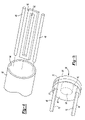
- FIG. 2 is a perspective, diagrammatic view of one example sensor embodiment.
- FIG. 3 is a cross-sectional illustration taken along the lines 3 — 3 in FIG. 2 .
- FIG. 4 is an exploded view of selected portions of the embodiment of FIGS. 2 and 3 .
- FIG. 5 schematically shows selected features of the example embodiment.
- FIG. 1 schematically shows a sensor arrangement 20 for determining one or more characteristics of a fluid 22 within a container 24 .
- the sensor 20 is at least capable of determining a fluid level within the container 24 .
- the illustrated example includes a sensor device 30 that is adapted to be placed within the container 24 . More specifically, a sleeve 32 is inserted into the container 24 and a housing portion 34 near one end of the sleeve 32 remains outside of the container 24 .
- the housing portion 34 includes electrical connections for communicating power, signals or both between appropriate portions of the sensor device 30 and a controller 36 .
- an example sensor device includes a sleeve 32 including a plurality of openings 38 that allow fluid 22 from within the container 24 to enter an interior, open central portion of the sleeve 32 .
- the openings 38 are strategically positioned to allow a level of fluid within the sleeve 32 to correspond in a determined or expected manner, to a level of fluid within the container 24 . That way, determinations regarding a level of fluid within the sleeve 32 provides an indication of a level of fluid 22 within the container 24 .
- the housing 34 includes a connection portion 40 for making appropriate electrically conductive connections with at least one device such as the controller 36 .
- An opposite end 42 of the sleeve 32 supports a capacitive sensor element that provides an indication regarding one or more characteristics of the fluid 22 .
- a capacitive arrangement provides an indication regarding a concentration level of one or more selected components within the fluid 22 .
- One example use for this example device is to determine a urea concentration level within a mixture used for a selective catalytic reaction converter for controlling vehicle exhaust emissions.
- the capacitive element operates according to the teachings of U.S. patent application Ser. No. 10/869,137. The teachings of that document are incorporated into this description by reference.
- the open central portion of the sleeve 32 has an interior opening 44 that extends along the length of the sleeve 32 .
- a plurality of conductors 46 and 48 extend along a selected length of the interior of the sleeve 32 .
- the conductors 46 and 48 in this example comprise hollow tubes that extend essentially along the entire length of the opening 44 .
- the tubes are made of stainless steel.
- Selectively powering one or both of the conductors 46 and 48 establishes a conductivity field carried by the conductive fluid within the sleeve 32 .
- the conductivity of the fluid between the two conductors 46 and 48 provides an indication of a level of fluid within the sleeve 32 . More fluid within the sleeve corresponds to a higher conductivity value, which can be determined by the controller 36 using known techniques.
- the conductors operate as electrodes of a capacitive sensing element.
- a voltage output provides an indication of the actual conductivity between the conductors 46 and 48 resulting from the presence of the fluid 22 within the sleeve 32 .
- the conductivity field within the sleeve 32 may be unmanageably large, in part depending on the fluid within the sleeve 32 .
- the illustrated example includes a channel member 50 within the sleeve 32 to control how much of the conductivity field is used for level measurements.
- the channel member 50 has an electrically isolating (i.e., non-conductive) body with a central channel or opening 52 extending through a central portion of the channel member 50 .
- the channel or opening 52 directs a portion 54 of the conductivity field between the conductors 46 and 48 as schematically shown in FIG. 3 , for example.
- the electrically isolating body of the channel member 50 blocks a remaining portion 56 of the conductivity field within the sleeve 32 .
- the channel member 50 effectively controls the amount of conductivity field used for making a conductivity measurement between the conductors 46 and 48 .
- the illustrated example provides a level sensing device that has excellent resolution for a variety of fluids. Even highly conductive fluids such as urea can be measured using the example device.
- the sleeve 32 and the channel member 50 each comprise one of polytetrafluoroethylene (e.g., TEFLON®) or a polyphthalamide material. Such materials are selected for an embodiment used for measuring urea levels, for example.
- TEFLON® polytetrafluoroethylene
- a polyphthalamide material such materials are selected for an embodiment used for measuring urea levels, for example.
- One example includes the channel member as a portion of the sleeve 32 integrally formed with the sleeve 32 .
- One example includes wall-like extensions projecting inward in the sleeve to establish an open channel that is smaller than an interior of the sleeve.
- the conductors 46 and 48 are diametrically opposed from each other within the sleeve 32 .
- the channel member 50 is aligned generally perpendicular to a line extending between the conductors 46 and 48 .
- the opening or channel 52 through the channel member 50 allows for taking conductivity measurements using the portion 54 of the conductivity field that is directed through the opening 52 of the channel member 50 .
- one of the conductors 46 is grounded and the other is powered using an oscillator.
- the controller 36 uses known measurement principles for determining a conductivity level between the conductors 46 and 48 . Depending on the measurement, a determination regarding a level of fluid within the sleeve 32 can be made. Calibration and empirical testing can be used in one example to determine a number of values for relating conductivity measurements to fluid levels. As more of each conductor is immersed in the fluid, greater conductivity between them exists and a different measurement occurs, depending on the level of fluid between them.
- one example arrangement for securing one end of the conductors 46 and 48 in a desired position relative to the sleeve 32 and the channel member 50 includes a non-conductive disk member 60 .
- the conductor 46 extends through an opening 62 in the disk member 60 .
- An end of the conductor 46 is electrically coupled to an electrode 64 of a capacitive sensing element 66 that includes another electrode 68 .
- the electrode 64 is grounded and the conductor 46 is welded to a portion of the electrode 64 . Accordingly, the conductor 46 is grounded, also.
- the capacitive sensor portion 66 including the electrodes 64 and 68 provides a conductivity measurement that is useful for making a concentration level determination regarding the fluid 22 .
- a conductivity measurement from the capacitive sensor portion 66 provides a base line conductivity measurement useful in making the level determination based upon the conductivity determination resulting from the portion 54 of the conductivity field that is directed by the channel member 50 between the conductors 46 and 48 .
- the non-conductive disk member 60 supports the electrode 68 in a desired position relative to the electrode 64 .
- the end of the conductor 48 in this example is embedded in the disk member 60 so that it is held in place and electrically isolated from the electrodes 64 and 68 and the conductor 46 .
- Opposite ends of the conductors 46 and 48 are secured in place near the housing portion 34 .
- maintaining a desired alignment of the conductors 46 and 48 and the channel member 50 ensures accurate measurements.
- the conductors 46 and 48 in this example comprise hollow tubes.
- the interior portions of the tubes accommodate conductive leads 70 that are used for coupling the electrodes 64 and 68 , respectively, to appropriate electronics within the housing 34 or selected portions of the controller 36 .
Abstract
Description
Claims (22)
Priority Applications (1)
| Application Number | Priority Date | Filing Date | Title |
|---|---|---|---|
| US11/071,820 US7222528B2 (en) | 2005-03-03 | 2005-03-03 | Fluid level sensor |
Applications Claiming Priority (1)
| Application Number | Priority Date | Filing Date | Title |
|---|---|---|---|
| US11/071,820 US7222528B2 (en) | 2005-03-03 | 2005-03-03 | Fluid level sensor |
Publications (2)
| Publication Number | Publication Date |
|---|---|
| US20060196263A1 US20060196263A1 (en) | 2006-09-07 |
| US7222528B2 true US7222528B2 (en) | 2007-05-29 |
Family
ID=36942814
Family Applications (1)
| Application Number | Title | Priority Date | Filing Date |
|---|---|---|---|
| US11/071,820 Expired - Fee Related US7222528B2 (en) | 2005-03-03 | 2005-03-03 | Fluid level sensor |
Country Status (1)
| Country | Link |
|---|---|
| US (1) | US7222528B2 (en) |
Cited By (9)
| Publication number | Priority date | Publication date | Assignee | Title |
|---|---|---|---|---|
| US20040251919A1 (en) * | 2003-06-16 | 2004-12-16 | Siemens Vdo Automotive Corporation | Method of measuring the concentration of a fluid component that has a variable dielectric characteristic |
| US20070056365A1 (en) * | 2005-08-08 | 2007-03-15 | Siemens Vdo Automotive Corporation | Fluid quality sensor |
| US20090064776A1 (en) * | 2007-09-12 | 2009-03-12 | Electrolab, Inc. | Floatless rain gauge |
| US20090148306A1 (en) * | 2007-12-07 | 2009-06-11 | Melissa Drechsel | Capacitive liquid level sensor |
| US20090182467A1 (en) * | 2008-01-10 | 2009-07-16 | Felix Nedorezov | Indicating a Low Volume of Fluid in a Transmission Sump |
| US20110056289A1 (en) * | 2009-09-07 | 2011-03-10 | Senghaas Karl A | Floatless Rain Gauge |
| WO2012034199A2 (en) | 2010-09-15 | 2012-03-22 | Robert Bosch Limitada | Fuel level sensor, method for measuring fuel level by electrical conductivity and method for identifying the type of ethanol/gasoline fuel blend |
| US8978450B2 (en) | 2010-07-22 | 2015-03-17 | Watlow Electric Manufacturing Company | Combination fluid sensor system |
| CN105021260A (en) * | 2015-08-06 | 2015-11-04 | 方冰熔 | Water level gauge |
Families Citing this family (7)
| Publication number | Priority date | Publication date | Assignee | Title |
|---|---|---|---|---|
| DE102005025576A1 (en) * | 2005-06-03 | 2006-12-07 | Gestra Ag | Capacitive level probe |
| US7814788B2 (en) * | 2006-10-20 | 2010-10-19 | Abbott Laboratories, Inc. | Liquid level sensor |
| DE102007037364A1 (en) * | 2007-08-08 | 2009-02-12 | Robert Bosch Gmbh | liquid sensor |
| DE102007056544A1 (en) * | 2007-11-23 | 2009-05-28 | Robert Bosch Gmbh | Sensor arrangement for determining a tank level and method for producing this |
| DE102008041723A1 (en) * | 2008-08-29 | 2010-03-04 | Robert Bosch Gmbh | Tank for storing a liquid agent |
| GB201205074D0 (en) * | 2012-03-22 | 2012-05-09 | Airbus Operations Ltd | Sensor device and method for communicating with sensor devices |
| ES2773181T3 (en) * | 2017-02-22 | 2020-07-09 | Zodiac Aerotechnics | Condenser fuel probe |
Citations (29)
| Publication number | Priority date | Publication date | Assignee | Title |
|---|---|---|---|---|
| US4426616A (en) | 1981-10-06 | 1984-01-17 | Simmonds Precision Products, Inc. | Capacitive measurement system |
| US4428026A (en) * | 1979-09-06 | 1984-01-24 | Drexelbrook Controls, Inc. | Two layer probe |
| US4555661A (en) | 1983-04-11 | 1985-11-26 | Forte Technology, Inc. | Method and apparatus for determining dielectric constant |
| GB2210459A (en) | 1987-09-30 | 1989-06-07 | Vaponics | In-line concentric conductivity cell |
| US4915084A (en) | 1988-11-08 | 1990-04-10 | General Motors Corporation | Combustion engine with multi-fuel capability |
| US4924702A (en) * | 1989-03-10 | 1990-05-15 | Kavlico Corporation | Liquid level sensor |
| US4945863A (en) | 1988-03-30 | 1990-08-07 | Fev Motorentechnik Gmbh & Co. Kg | Process for operating a fuel-burning engine |
| US4971015A (en) | 1988-11-08 | 1990-11-20 | General Motors Corporation | Combustion engine with multi-fuel capability |
| US5060619A (en) | 1989-11-10 | 1991-10-29 | Japan Electronic Control Systems Co., Ltd. | Electrostatic capacity type fuel concentration monitoring unit with temperature dependent fluctuation compensating feature |
| US5089703A (en) | 1991-05-16 | 1992-02-18 | Finnigan Corporation | Method and apparatus for mass analysis in a multipole mass spectrometer |
| US5103184A (en) | 1990-11-16 | 1992-04-07 | General Motors Corporation | Capacitive fuel composition sensor with ground isolation |
| US5119671A (en) | 1991-03-12 | 1992-06-09 | Chrysler Corporation | Method for flexible fuel control |
| US5134381A (en) | 1989-07-01 | 1992-07-28 | Fev Motorentechnik Gmbh & Co., Kg | Method of analyzing the alcohol content and/or the calorific value of fuels |
| US5216409A (en) | 1991-09-03 | 1993-06-01 | General Motors Corporation | Method and apparatus for detecting a contaminated alcohol-gasoline fuel mixture |
| US5231358A (en) | 1990-11-16 | 1993-07-27 | General Motors Corp. | Capacitive fuel composition sensor with slow oscillator and high speed switch |
| US5230322A (en) | 1992-11-06 | 1993-07-27 | Ford Motor Company | Method and apparatus for compensating for errors associated with a fuel type sensor |
| US5255656A (en) | 1991-06-27 | 1993-10-26 | Borg-Warner Automotive, Inc. | Alcohol concentration sensor for automotive fuels |
| US5301542A (en) | 1992-02-11 | 1994-04-12 | Ford Motor Company | Flexible fuel PI filter sensor |
| US5361035A (en) | 1992-02-11 | 1994-11-01 | Ford Motor Company | Resonant cavity flexible fuel sensor and system |
| US5367264A (en) | 1990-11-16 | 1994-11-22 | Siemens Ag | Measuring instrument and method for determining the alcohol content of a mixture |
| US5416425A (en) | 1991-11-19 | 1995-05-16 | Siemens Automotive S.A. | Sensor for determining electrical characteristics of a flowing liquid |
| US5503004A (en) | 1988-02-11 | 1996-04-02 | Agar Corporation Inc. | Apparatus for determining the percentage of a fluid in a mixture of fluids |
| US5594163A (en) | 1994-05-12 | 1997-01-14 | Mitsubishi Denki Kabushiki Kaisha | Fuel mixing ratio detecting device |
| US5661405A (en) * | 1995-11-06 | 1997-08-26 | Simon; Jay S. | Elongate sensor having polymeric electrodes filled with conductive particles and having braided sleeves |
| US5717339A (en) | 1996-08-28 | 1998-02-10 | He Holdings, Inc. | Dielectric mixture composition linear sensor with compensation for mixture electrical conductivity |
| US5945831A (en) | 1997-06-10 | 1999-08-31 | Sargent; John S. | Volume charge density measuring system |
| DE19938790A1 (en) | 1999-08-16 | 2001-02-22 | Siemens Ag | Determination of the fuel concentration in the electrolyte of fuel cells operated with liquid fuel |
| WO2002027280A2 (en) | 2000-09-26 | 2002-04-04 | Siemens Aktiengesellschaft | Method and device for determining the level of a liquid in a container |
| US20030000303A1 (en) * | 2001-06-25 | 2003-01-02 | Livingston Richard A. | Auto-compensating capacitive level sensor |
Family Cites Families (1)
| Publication number | Priority date | Publication date | Assignee | Title |
|---|---|---|---|---|
| US5134361A (en) * | 1991-02-19 | 1992-07-28 | The United States Of America As Represented By The Secretary Of The Navy | Opitcal system for linearizing non-linear electro-optic |
-
2005
- 2005-03-03 US US11/071,820 patent/US7222528B2/en not_active Expired - Fee Related
Patent Citations (30)
| Publication number | Priority date | Publication date | Assignee | Title |
|---|---|---|---|---|
| US4428026A (en) * | 1979-09-06 | 1984-01-24 | Drexelbrook Controls, Inc. | Two layer probe |
| US4426616A (en) | 1981-10-06 | 1984-01-17 | Simmonds Precision Products, Inc. | Capacitive measurement system |
| US4555661A (en) | 1983-04-11 | 1985-11-26 | Forte Technology, Inc. | Method and apparatus for determining dielectric constant |
| GB2210459A (en) | 1987-09-30 | 1989-06-07 | Vaponics | In-line concentric conductivity cell |
| US5503004B1 (en) | 1988-02-11 | 2000-11-07 | Agar Corp Inc | Apparatus for determining the percentage of a fluid in a mixture of fluids |
| US5503004A (en) | 1988-02-11 | 1996-04-02 | Agar Corporation Inc. | Apparatus for determining the percentage of a fluid in a mixture of fluids |
| US4945863A (en) | 1988-03-30 | 1990-08-07 | Fev Motorentechnik Gmbh & Co. Kg | Process for operating a fuel-burning engine |
| US4971015A (en) | 1988-11-08 | 1990-11-20 | General Motors Corporation | Combustion engine with multi-fuel capability |
| US4915084A (en) | 1988-11-08 | 1990-04-10 | General Motors Corporation | Combustion engine with multi-fuel capability |
| US4924702A (en) * | 1989-03-10 | 1990-05-15 | Kavlico Corporation | Liquid level sensor |
| US5134381A (en) | 1989-07-01 | 1992-07-28 | Fev Motorentechnik Gmbh & Co., Kg | Method of analyzing the alcohol content and/or the calorific value of fuels |
| US5060619A (en) | 1989-11-10 | 1991-10-29 | Japan Electronic Control Systems Co., Ltd. | Electrostatic capacity type fuel concentration monitoring unit with temperature dependent fluctuation compensating feature |
| US5103184A (en) | 1990-11-16 | 1992-04-07 | General Motors Corporation | Capacitive fuel composition sensor with ground isolation |
| US5231358A (en) | 1990-11-16 | 1993-07-27 | General Motors Corp. | Capacitive fuel composition sensor with slow oscillator and high speed switch |
| US5367264A (en) | 1990-11-16 | 1994-11-22 | Siemens Ag | Measuring instrument and method for determining the alcohol content of a mixture |
| US5119671A (en) | 1991-03-12 | 1992-06-09 | Chrysler Corporation | Method for flexible fuel control |
| US5089703A (en) | 1991-05-16 | 1992-02-18 | Finnigan Corporation | Method and apparatus for mass analysis in a multipole mass spectrometer |
| US5255656A (en) | 1991-06-27 | 1993-10-26 | Borg-Warner Automotive, Inc. | Alcohol concentration sensor for automotive fuels |
| US5216409A (en) | 1991-09-03 | 1993-06-01 | General Motors Corporation | Method and apparatus for detecting a contaminated alcohol-gasoline fuel mixture |
| US5416425A (en) | 1991-11-19 | 1995-05-16 | Siemens Automotive S.A. | Sensor for determining electrical characteristics of a flowing liquid |
| US5361035A (en) | 1992-02-11 | 1994-11-01 | Ford Motor Company | Resonant cavity flexible fuel sensor and system |
| US5301542A (en) | 1992-02-11 | 1994-04-12 | Ford Motor Company | Flexible fuel PI filter sensor |
| US5230322A (en) | 1992-11-06 | 1993-07-27 | Ford Motor Company | Method and apparatus for compensating for errors associated with a fuel type sensor |
| US5594163A (en) | 1994-05-12 | 1997-01-14 | Mitsubishi Denki Kabushiki Kaisha | Fuel mixing ratio detecting device |
| US5661405A (en) * | 1995-11-06 | 1997-08-26 | Simon; Jay S. | Elongate sensor having polymeric electrodes filled with conductive particles and having braided sleeves |
| US5717339A (en) | 1996-08-28 | 1998-02-10 | He Holdings, Inc. | Dielectric mixture composition linear sensor with compensation for mixture electrical conductivity |
| US5945831A (en) | 1997-06-10 | 1999-08-31 | Sargent; John S. | Volume charge density measuring system |
| DE19938790A1 (en) | 1999-08-16 | 2001-02-22 | Siemens Ag | Determination of the fuel concentration in the electrolyte of fuel cells operated with liquid fuel |
| WO2002027280A2 (en) | 2000-09-26 | 2002-04-04 | Siemens Aktiengesellschaft | Method and device for determining the level of a liquid in a container |
| US20030000303A1 (en) * | 2001-06-25 | 2003-01-02 | Livingston Richard A. | Auto-compensating capacitive level sensor |
Non-Patent Citations (7)
| Title |
|---|
| PCT International Search Report for PCT/US02/15931 mailed Aug. 26, 2002. |
| U.S. Appl. No. 10/150,903, filed May 17, 2002. |
| U.S. Appl. No. 10/284,433, filed Oct. 30, 2002. |
| U.S. Appl. No. 10/452,840, filed Jun. 2, 2003. |
| U.S. Appl. No. 10/991,245, filed Nov. 17, 2004. |
| U.S. Appl. No. 10/991,579, filed Nov. 18, 2004. |
| U.S. Appl. No. 11/071,853, filed Mar. 3, 2005. |
Cited By (13)
| Publication number | Priority date | Publication date | Assignee | Title |
|---|---|---|---|---|
| US20040251919A1 (en) * | 2003-06-16 | 2004-12-16 | Siemens Vdo Automotive Corporation | Method of measuring the concentration of a fluid component that has a variable dielectric characteristic |
| US20070056365A1 (en) * | 2005-08-08 | 2007-03-15 | Siemens Vdo Automotive Corporation | Fluid quality sensor |
| US7466147B2 (en) | 2005-08-08 | 2008-12-16 | Continental Automotive Systems Us, Inc. | Fluid quality sensor |
| US7584656B2 (en) * | 2007-09-12 | 2009-09-08 | Electrolab, Inc. | Floatless rain gauge |
| US20090064776A1 (en) * | 2007-09-12 | 2009-03-12 | Electrolab, Inc. | Floatless rain gauge |
| US20090148306A1 (en) * | 2007-12-07 | 2009-06-11 | Melissa Drechsel | Capacitive liquid level sensor |
| US8936444B2 (en) | 2007-12-07 | 2015-01-20 | Pentair Flow Technologies, Llc | Capacitive liquid level sensor |
| US20090182467A1 (en) * | 2008-01-10 | 2009-07-16 | Felix Nedorezov | Indicating a Low Volume of Fluid in a Transmission Sump |
| US7761202B2 (en) | 2008-01-10 | 2010-07-20 | Ford Global Technologies, Llc | Indicating a low volume of fluid in a transmission sump |
| US20110056289A1 (en) * | 2009-09-07 | 2011-03-10 | Senghaas Karl A | Floatless Rain Gauge |
| US8978450B2 (en) | 2010-07-22 | 2015-03-17 | Watlow Electric Manufacturing Company | Combination fluid sensor system |
| WO2012034199A2 (en) | 2010-09-15 | 2012-03-22 | Robert Bosch Limitada | Fuel level sensor, method for measuring fuel level by electrical conductivity and method for identifying the type of ethanol/gasoline fuel blend |
| CN105021260A (en) * | 2015-08-06 | 2015-11-04 | 方冰熔 | Water level gauge |
Also Published As
| Publication number | Publication date |
|---|---|
| US20060196263A1 (en) | 2006-09-07 |
Similar Documents
| Publication | Publication Date | Title |
|---|---|---|
| US7222528B2 (en) | Fluid level sensor | |
| US7030629B1 (en) | In line fluid quality sensor | |
| US7466147B2 (en) | Fluid quality sensor | |
| US7170303B2 (en) | Fuel sensor | |
| EP1906176B1 (en) | Liquid state sensor | |
| CA2324843C (en) | Monitoring fluid condition through an aperture | |
| US6722213B2 (en) | Temperature-adjusted sampler for fluids | |
| US6529017B2 (en) | Capacitance level measurement circuit and system | |
| US4814059A (en) | Electrochemical device having a heater and leak protection electrode | |
| US20090212779A1 (en) | Battery Sensor Unit | |
| CN115485528A (en) | Magnetic-inductive flow measuring device and method for determining a fill level | |
| US20080148810A1 (en) | Device For Determining the Level of a Fluid | |
| US11326925B2 (en) | Probe unit with a securement unit that releasably secures an electrode on the probe body | |
| US6781389B1 (en) | Conductivity sensor for detecting conductivity of a fluid | |
| JP4782506B2 (en) | Capacitive sensor | |
| US5012197A (en) | Apparatus and method for determining the relative percentages of components in a mixture | |
| JP2001289819A (en) | Electrochemical measuring sensor | |
| JP3544981B2 (en) | Oxygen measurement sensor | |
| JP2001004584A (en) | Gas sensor | |
| US11573197B2 (en) | Gas sensor with angled sealing element | |
| US4127463A (en) | Probe for an electrochemical oxygen measurement pickup | |
| JP4901535B2 (en) | Bio-related substance measuring device | |
| US20190072507A1 (en) | Probe for determining humidity | |
| US11371871B2 (en) | Sensor unit, fluid power unit with sensor unit and method for measuring parameters of a fluid | |
| US7972489B2 (en) | Sensor element |
Legal Events
| Date | Code | Title | Description |
|---|---|---|---|
| AS | Assignment |
Owner name: SIEMENS VDO AUTOMOTIVE CORPORATION, MICHIGAN Free format text: ASSIGNMENT OF ASSIGNORS INTEREST;ASSIGNORS:STAHLMANN, DANIEL;MCKENZIE, ISABELLE;WILDESON, RAY;REEL/FRAME:016352/0342;SIGNING DATES FROM 20050228 TO 20050301 |
|
| STCF | Information on status: patent grant |
Free format text: PATENTED CASE |
|
| FEPP | Fee payment procedure |
Free format text: PAYOR NUMBER ASSIGNED (ORIGINAL EVENT CODE: ASPN); ENTITY STATUS OF PATENT OWNER: LARGE ENTITY |
|
| FPAY | Fee payment |
Year of fee payment: 4 |
|
| FPAY | Fee payment |
Year of fee payment: 8 |
|
| AS | Assignment |
Owner name: CONTINENTAL AUTOMOTIVE SYSTEMS US, INC., MICHIGAN Free format text: CHANGE OF NAME;ASSIGNOR:SIEMENS VDO AUTOMOTIVE CORPORATION;REEL/FRAME:034979/0865 Effective date: 20071203 |
|
| AS | Assignment |
Owner name: CONTINENTAL AUTOMOTIVE SYSTEMS, INC., MICHIGAN Free format text: MERGER;ASSIGNOR:CONTINENTAL AUTOMOTIVE SYSTEMS US, INC.;REEL/FRAME:035091/0577 Effective date: 20121212 |
|
| FEPP | Fee payment procedure |
Free format text: MAINTENANCE FEE REMINDER MAILED (ORIGINAL EVENT CODE: REM.); ENTITY STATUS OF PATENT OWNER: LARGE ENTITY |
|
| LAPS | Lapse for failure to pay maintenance fees |
Free format text: PATENT EXPIRED FOR FAILURE TO PAY MAINTENANCE FEES (ORIGINAL EVENT CODE: EXP.); ENTITY STATUS OF PATENT OWNER: LARGE ENTITY |
|
| STCH | Information on status: patent discontinuation |
Free format text: PATENT EXPIRED DUE TO NONPAYMENT OF MAINTENANCE FEES UNDER 37 CFR 1.362 |
|
| FP | Lapsed due to failure to pay maintenance fee |
Effective date: 20190529 |