US721202A - Facsimile-telegraph. - Google Patents
Facsimile-telegraph. Download PDFInfo
- Publication number
- US721202A US721202A US436800A US1900004368A US721202A US 721202 A US721202 A US 721202A US 436800 A US436800 A US 436800A US 1900004368 A US1900004368 A US 1900004368A US 721202 A US721202 A US 721202A
- Authority
- US
- United States
- Prior art keywords
- stylus
- paper
- shaft
- armature
- platen
- Prior art date
- Legal status (The legal status is an assumption and is not a legal conclusion. Google has not performed a legal analysis and makes no representation as to the accuracy of the status listed.)
- Expired - Lifetime
Links
Images


Classifications
-
- H—ELECTRICITY
- H04—ELECTRIC COMMUNICATION TECHNIQUE
- H04N—PICTORIAL COMMUNICATION, e.g. TELEVISION
- H04N1/00—Scanning, transmission or reproduction of documents or the like, e.g. facsimile transmission; Details thereof
- H04N1/32—Circuits or arrangements for control or supervision between transmitter and receiver or between image input and image output device, e.g. between a still-image camera and its memory or between a still-image camera and a printer device
- H04N1/36—Circuits or arrangements for control or supervision between transmitter and receiver or between image input and image output device, e.g. between a still-image camera and its memory or between a still-image camera and a printer device for synchronising or phasing transmitter and receiver
Definitions
- This invention relates to that class of telegraphic mechanism or apparatus which is generally known by the term facsimile-telegraph and which is designed for the trans- I5 mission in facsimile of manuscript messages or pictures or other matter which is written ,or drawn upon a sending blank or sheet.
- My invention has particular relation to facv simile-telegraphs which embodyin the trans- 2o mitting machine or apparatus a stylus mechanism which contacts with ametal-foil sheet on which the mattergto' be transmitted is written or drawn with an insulating-ink, the contact of the Vstylus device with said insulated portions being arranged and adapted to send an impulse over the line aud'cause a corresponding actuation of an electromagnet i stylus device comprised inthe receiving machine vor apparatus, whereby the recording 5o stylus mechanism will operate to mark or record in facsimile the matter thus transmitted.
- the object of my invention is to produce an improved facsimile telegraph in which perfect synchronism between thesending and receiving machines Awill be continuouslyT maintained, which will operate continuously without occasion for frequent stoppageof the machines for the application or insertion of 4o new matter to be transmitted, which by continuous operation will rapidly transmit a large amount or area of matter, which will be exceedingly simple in construction and mechanism and rapid and effective/in operation, and which will attain a maximum degree of economy and convenience in use.
- Figure l is a general side elevation, partly in section and with parts of the inclosing casing broken away, illustrating the transmitting machine or apparatus embodied in my invention.
- Fig. 2 is a ⁇ vertical transverse sectional Viena-taken from front to rear, of the transmitting-machine.
- Fig. 3 is a top or plan View of the transmitting-machine, parts ofthe top of the casing being broken away.
- Fig. 4 is a horizontal sectional view taken through the 6o transmitting-machine on the line Al lof Fig. 2, parts'being broken away to better show the underlying structure.
- Fig. 1 is a general side elevation, partly in section and with parts of the inclosing casing broken away, illustrating the transmitting machine or apparatus embodied in my invention.
- Fig. 2 is a ⁇ vertical transverse sectional Viena-taken from front to rear, of the transmitting-machine.
- Fig. 3 is a top or plan View of the
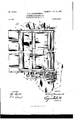
- FIG. 5 is a detail top or plan view illustrating the Inessage-paper-feed mechanism of the transmitting-machine'.
- Fig. 6 is a detail side view of the feed-,mechanism illustrated in Fig. 5.
- Fig. 'Z is a. detail top or plan, view of thestylus short-circuiter for the transmitting-machine.
- Fig. 8 is a detail side view V7o of said stylus short-circuiter.
- Fig. 9 is a detail top or plan View illustrating one of the polarized. receiving-relays which' are comprised in the line-circuitand arranged at the receiving or recording machine.
- Fig. 10 is 75 a detail side view of said polarized relay.
- Fig. 10 is 75 a detail side view of said polarized relay.
- 1l is a side elevation, partly in section and partly broken away, of the top portion of the receiving-machine embodied in my invention.
- Fig. 12 is a vertical transverse sec- 8o tional View taken from front. to rear of the top portion of the receiving-mac ine.
- Fig. 13 is a top or plan view of the receiving-machine, parts of the top of the casing being broken away.
- Fig. 14 is a detail plan view 85 illustrating one of the recording vstylus devices.
- Fig. 15 is a detail end elevation of one of the recording stylus devices looking toward thearmature.
- Fig. 16 is a detail vertical sectional view of one of the recording- 9o styluses.
- Fig. 12 is a vertical transverse sec- 8o tional View taken from front. to rear of the top portion of the receiving-mac ine.
- Fig. 13 is a top or plan view of the receiving-machine, parts of the top of the casing being broken away.'y
- Fig. 17 is adiagrammatic plan view illustrating the general theory of the circuits.
- Fig. 18 is a general diagrammatic plan'view illustrating the complete circuits of the transmitting-machine and the connection thereof with the single line-wire, and
- Fig. 19 is a correspondingdiagrammatic plan View illustrating the complete circuits of the receiving-machine and the connection thereof with the single line-wire.
- 11 designates a suitable framework which may be in Athe main ICO of any required or adapted construction, to which is suitably connected a casing 12, arranged to inolose the operative mechanism and of convenient or adapted construction for this purpose.
- a main vertical shaft 13 is centrally mounted within the framework and casing and carries at its top end in its revoluble movement the stylus-carrier 14, which may be a plate, as herein shown, or a webframe or othersuitable or adapted structure. r[he styluscarrier 14 is mounted in fixed relation upon the main shaft 13.
- the stylus-carrier 14 carries a series of transmitting stylus devices 15, which depend or project downwardly from the carrier and are arranged in a circular series at the peripheral portion of the latter.
- I may employ any suitable or desired number of suoli stylus devices; but in the present instance I have illustrated a set of ten, the relative construction and arrangement being such that two or a pair of the stylus devices will be simultaneously in operative position upon the metal-foil-paper sheet or blank at all times during the transmission of the matter upon said blank.
- the stylus devices are preferably equidistantly placed, and in the practical structure of the machine, as herein illustrated, three of said stylus devices may be simultaneously upon the foil-paper, (see Fig.
- the transmitting stylus devices 15 comprise a stylus contact-point 16 and may be in the main of any suitable or adapted construction. I prefer, however, to employa specific construction of stylus,which involves a yielding stylus-rod 17, carried within a cylindrical casing 18, having a broad-top disk 19, centrally secured by an adjustable screw 20 to the carrier-plate 14, and having a series of adjusting-screws 2l projecting from said member 14 and bearing against the disk 19 at points beyond the central screw 20, whereby said stylus device may be adjusted vertically, and is also subject to adjustment laterally or in a horizontal plane.
- a specific construction of stylus which involves a yielding stylus-rod 17, carried within a cylindrical casing 18, having a broad-top disk 19, centrally secured by an adjustable screw 20 to the carrier-plate 14, and having a series of adjusting-screws 2l projecting from said member 14 and bearing against the disk 19 at points beyond the central screw 20, whereby said stylus device may be adjusted vertically, and is also subject to adjustment laterally or in a
- the feed mechanism for effecting the carriage and continuous feed of the foil-paper message sheet or blank is arranged at the front and top portion of the framework and casing with relation to the line of travel of the transmittingstylus deviees15 and beneath the latter, so that the stylus-points 16 will describe an arc or segmental line of travel over the surface of the foil-paper and in contact with the same.
- This paper-feed mechanism comprises a suitable framework 22, which is preferably individual or separate with relation to the general framework of the machine and embodies vertical parallel sides 23 23, between which is sustained and carried the feeding mechanism.
- the framework 22 is mounted and secured upon the general framework 11, and between its sides 23 at the front extends ahorizontal table or platform 24, over which the foil-paper (represented at 25) initially passes to a platen 26, arranged in rear of the table 24 and extending in the plane of the are or line of travel of the styluses.
- a roller 27 Between the sides 23, above the table 24, is mounted a roller 27, and at the rear end of said framework 22 and between the sides thereof is mounted an idler or roller. 28, in front of which is mounted another roller 29, and beneath said roller 29 is mounted another roller 30.
- elastic bands or tapes 31 At each side of the feed mechanism are arranged elastic bands or tapes 31, the ofiice of which is to carry the messagepaper or blank 25 in a positive movement over the platen 26.
- rollers 29 and 30 have shaft extensions, as at 32 and 33, respectively, at one end, which respectively carry gears 34 and 35, which intermesh, whereby the revolution of the roller 30 (which is the main roller from which the feed mechanism derives its operation or movement) is communicated to the roller 29 for the purpose of insuring a more positive feed of the bands 31 and the foil-paper 25 by aetion of said roller 29.
- a brush contact device which is adapted to contact with or bear upon the foil surface of the message-paper 25, and while this contact device may be of any suitable or adapted construction I prefer to employ they brush device as comprised in my above-mentioned other application for patent and as herein illustrated, which comprises a fiexible metallic brush 36, extending transversely across and over the platen 26 and having its lower contact edge curved and provided with a series of parallel slits, as at 37, for the purpose of increasing its iieXibility, said brushplate 36 being carried upon a rod or shaft 38,
- the whole paper-feed-mechanism frame may be insulated from the main frame ll, as shown at 40, so that the whole of said framework 22 will be comprised in an electric circuit, the circuit connection being made by meansof a wire, as indicated at 4l; but under some circumstances only the foil-paper contact brush device need be comprised in circuit, in which case the wire connection 41 will bemade direct to saidbrush device and the latter will be properly insulated from the main framework of the paper-feed mechanism.
- the whole feed-mechanism framework 22 is comprisedin circuit, as herein illustrated, the insulation is completed by means of an insulated section, as at 42, upon the shaft of the roller 30, which shaft is in connection with the main operative mechanism of the machine.
- the platen 26 is adjustable vertically with relation to the degree of projection of the stylus-point 16, whereby the contact between the stylus and the foil surface of the message-paper' 25 may be suitably adjusted or governed as desired to insure a perfect degree of contact and perfect operation.
- This vertical adjustment of said platen is independent of the general paper-feed mechanism and is preferably accomplished by means of the following construction:
- the platen is mounted upon and carried by two transverse angular rockshafts 43 43, by the operation of which the platen can be adjusted upwardly and downwardly between the sides 23 of the paper-feedmechanism frame 22'in such'a manner that it will always maintain a uniform position on a horizontal plane.
- These shafts 43 are preferably respectively arranged at the front and rear portions of the platen, so that their straight main portions extend transversely beneath the latter and operate in bearings 44 at the under side of the same.
- Each outer end of the shafts 43 is provided with a crankarm 45, the outer end or pin 46 of which bears in the side 23 of the frame 22.
- the ends 46 of said shafts 43 are provided, outside the side 23, with supplementary crank-arms 47, the outer ends or pins 48 of which have bearings in the respective ends of a vertically-adjustable connecting-block or cross-piece 49, arranged on a plane parallel with relation to the platen 26.
- This block 49 is adapted to be moved or adjusted vertically by means of a screw 50,
- the portion of the screw 50 below the lower flange 53 is threaded, as at 55, which threaded portion operates in a block or portion, as at 56, comprised in the general framework 22, while above the upper ange 52 the stem of the screw is extended a suitable distance, as at 57, and provided with an operating yhead or knob 58, by which it may be conveniently turned.
- the inner crank-arms 45 of the shafts 43 extend in an inclined direction downwardly and rearwardly, while the outer crank-arms 47 of said shafts extend in an inclined direction upwardly and forwardly, whereby the platenwill be swung in an upward and rearward or downward and forward direction during its adjustment, but will be maintained in a proper horizontal plane at all periods of its adjustable movement.
- any suitable or adapted means for operating the block 49 in its vertical movement may be employed, if desired, in lieu of the screw 50.
- the platen By the simple turning of the screw 50 the platen will be correspondingly raised or lowered by theaction of the block 49 and the crank-shaft connections between the same and the platen.
- a particular function and advantage secured by the adjustability of the platen, as hereinabove described, is that the foil-paper message sheet or blank may be conveniently inserted initially into position beneath the styluses without danger of tearing or otherwise injuring the paper or injuring the stylus-points, it being simply necessary in this initial insertion of the paper to lower the platen, insert the paper over the same, and then raise the platen up to its normal position of vertical adjustment, in which the stylus-point will be in proper contact with the top surface of the paper.
- the platen may under some circumstances, if preferred, have the platen stationary and provide for the vertical adjustment of the stylus-carrier in the manner illustrated in my hereinbefore-mentioned other application for patent.
- the foil-paper is inserted beneath the initial roller 27 and beneath the elastic carrying and guide bands 31 and from thence passes inwardly and rearwardly and over the top surface of the platen and over and around the rear side of the roller 29 and between said latter roller and the bands 31, the positive contact and feed of said paper by means of said roller 29 and the bands 31 being insured by the direct-gear connection 34 between said roller 29 and the main operatingroller 30.
- the paper- 25 passes in a return movement forwardly between the sides 23 of the frame 22 and beneath the platen and out at the front o f the machine beneath the table 24, the continuous reverse movement of said paper inwardly and outwardly being thus attained.
- the direct operative connection between the main shaft 13 and the paper-feed mechanism is formed by means of a vertical shaft 61, having bearings in the general framework '11 and carrying a horizontal bevel-gear 62, meshing with the lower side of a bevel-gear 63, carried upon the end of the shaft of the roller 30, which is opposite from the end carrying the gear 35 and at a point beyond the insulation 42.
- This shaft 61 carries at its lower end a horizontal sprocket-wheel 64, connected by a sprocket-chain, as indicated at 65, with a sprocket-gear 66, carried by the main shaft 13.
- a direct-gear connection may be employed, if desired. The revolution of the shaft 13 is thus directly communicated to the paper-feed mechanism.
- I preferably provide for the independent operation of the paper-feed mechanism by hand, without operation of the main shaft 13, to enable the convenient initial insertion or adjustment of the foil message-paper when the stylnses are not revolving, and for this reason I employ a construction and mechanism approximately corresponding to that illustrated in my above-mentioned other application for patent, in which the shaft 61 is divided into an upper and lower section 67 and 68, respectively, said upper section carrying at its top end an operating knob or head 69 and carrying at its lower end, at a point beneath thegear62,a ratchet-disk 70,which is engaged by a pawl 71, carried by the lower portion'or section 68 of the shaft at a point above the gear 64.
- the paper-feed mechanism when the shaft 13 and the stylus mechanism are in operation the paper-feed mechanism will be operated in a corresponding relative movement by means of the paWl-andratchet coupling connection between the sections of the shaft 6l; but when said shaft 13 and the stylus mechanism are at rest the paper-feed mechanism may be independently operated by merely turning the upper shaftsection 67 in its independent movement with respect to the lower shaft-section 68.
- the circuit connections for the respective stylus devices 15 are made through the medium of a commutator which I term a styluscommutator 72, which is mounted upon the main shaft 13, preferably at the top portion thereof and adjacent to the plane of projection of the styluses.
- This commutator carries a continuous ring 73 and two separate ring sets of segments 74 and 75, respectively.
- I divide the set of stylus devices 15 into'two sets or series and also alternately arrange said stylus devices of the respective sets in relation to their successive line of travel.
- each segmental ring set 74 and 75 will comprise five segments, as at 76 and 77, respectively, and each stylus device 15 is individually or separately connected by a wire 78 with its respective commutator-segment.
- the relative arrangement of the segments of the two segmental commutator sets is such that the interval of insulation, as at 79, between the segments of one set will be on a plane intersecting the central portion of the segments of the other set, whereby when one stylus is just entering uponits operative contact with the foilpaper the other stylus of the simultaneouslyoperating pair will be in its operati-ve contact at approximately the middle of the foil-paper sheet or blank, and a pair of said styluses will thus be always maintained in operative position.
- this relative arrangement of the commutator-segments of the dierent sets is, with relation to the brushdcontacts which project into operative position with relation to the segments, all on the same plane of projection, as clearly shown in Fig. 1.
- a brush-contact is provided for the three ring-sets of the commutator 72, as shown at 80, 8l, and 82, the brush 80 serving the segmental set 74, while the brush 81 serves the segmental set 75 and the brush 82 serves the continuous ring 73.
- the intervals of insulation 79 between the segments 7G and 77 of the respective segmental sets 74 and 75 are provided short intermediate segments, there being thus five such intermediate segments in each segmental set 74 and 75, the intermediate segments of the set 74 being designated by the numerals 83 and the intermediate segments of the segmental set 75 being designated by the numerals 84.
- All of theseintermediate segments 83 and 84 are connected with the continuous commutator-ring 73, this being preferably eected by means of wires, as at 85, extending between the segments 83 and 84, and by means of similar wires or connect- ⁇ ing-pieces 86, extending between the segments 84 and the ring 73.
- These intermediate short segments are concerned in the sending of synchronizingimpulses, and also in the sending of transmitting and synchronizing impulses at the same time under certain conditions, as will be hereinafter described.
- the main shaft 13 is supported upon a suitable ballbearing, which may be formed by a disk 90, secured to the shaft and bearing against a set of balls 91, which operate in a ball retainer or socket-piece 92, supported upon the general machine framework 11, the preferred construction being such that said member 92 is supported upon a transverse horizontal web-plate 93, extending within and between the portion of the casing 94 which constitutes the top part of the machine and which incloses the stylus and paper-feed mechanism,
- the main shaft 13 is adapted to be locked against the action of the continuously-operating motor mechanism by which it is revolved, this locking being automatically and electrically accomplished by impulses over the line and serving to insure the simultaneous starting vof the transmitting and receiving machines comprised in the same line-circuit by means of the automatic simultaneous release of the stop mechanism.
- the motor mechanism which operates the machines may be run continuously, yet the machines may be independently stopped in unison and independently started in unison.
- the devices included in this stop mechanism comprise a unison-magnet 97, the armature 98 of which carries at its outer end a supplementary arm 99, which is pivotally connected to the armature, as at 100, so that it can turn or operate in a plane at right angles to the plane of movement of the armature.
- Said arm carries a projecting nger 101, which is adapted to be thrown into engagement with a worm 102 upon the shaft 13, which Worm leads to a stop-shoulder 103 upon the periphery of a disk 104, which is mounted upon the shaft 13.
- the relative construction and arrangement are such that when the armature 98 is released the finger 101 will be projected into engagement with .IOO
- I provide an air or spring cushion device 105, embodying a plunger o', which bears against the armature 98 in such a manner that it will retard the action of the armature when it is released by its magnet, (thus causing a slow movement in the operation of throwing the finger 101 into engagement with the worm,) but will quicken or accelerate the action or movement of the armature when itis attracted by its magnet, thus quickening or making instantaneous the release of said arm 99 and its finger 101 from any engagement. with the top devices upon the shaft.
- the unison-magnet 97 and its armature and the cushion-resistance device 105 suitably depending from and support-ed by the cross-plate 93, which is comprised inthe top framework or casing structure 94:, the worm 102 and disk 101 being relat-ively arranged upon the shaft 13 at a point just beneath said plate 93 and preferably just above the gear 66.
- the unison-magnet and stop mechanism is indicated in dotted lines in Fig. 3 and is shown in part in full lines in Fig. 1, it being unnecessary in the present application to specifically duplicate the full illustration of these particular parts, which will be found in my other application.
- the respective circuit-wires connected with the unison-magnet 97 are indicated at 107 and 108.
- I provide a synchronizer in direct connectionwith the main shaft 13.
- This synchronizer is preferably arranged within the base portion of the machine-casing 9-1 and just above a bottom plate 109,comprised in the general framework 11, the relative machine structure being preferably such that said bottom ⁇ plate supports the casing 94C and rests upon a suitable table or other supporting-platform, as indicated at 110.
- the synchronizer embodies the general structural features of an electric motor, and comprises a central armature 111, which is mounted upon the main shaft 13 preferably at a point just beneath the gear connection between said shaft and the paper-feed mechanism. This armature revolves within a circular field 112, comprised in said synchronizer.
- Said field preferably comprises a ring-shaped body 113, which rests Within a shouldered recess, as at 114, in an upwardlyprojecting flange 115, extending from the base-plate 109 and surrounding a circular opening in said base-plate, whereby the synchronizer-lield is conveniently mounted in position, which general arrangement forms a convenient, economic, and simple structure.
- Both the armature 111 and field 113 are provided with a corresponding number of poles 116 and 117, respectively, the number of said poles upon each member of the synchronizer preferably corresponding to the number of stylus devices, and vtherefore hobos in the present illustration ten in number.
- the synchronizer is best adapted for the sending of impulses at every tenth period in one complete revolution of the stylus-carrier, thusenabling the sending of a synchronizing impulse foreach stylus device and when the synchroniZer-poles are 0pposite each other.
- the arrangement is preferably such that these synchronizingimpulses are always sent when the respective stylus devices are at the center of the foil-paper sheet or blank 25.
- the sending of the synchronizingimpulses and the means by which such impulses are sent at said definite point with relation to the position of the stylus device will be hereinafter fully described. It will be noted that I may vary the number of poles comprised in the synchronizer with respect to the number of stylus devices comprised in the complete stylus set.
- said poles may be less in number than the stylus devices or greater in number or may be provided in any lesser or greater multiples of the pairs of stylus devices, so long as the poles of armature and field are opposite at the time of sending the synchronizing IOC l'IO
- the poles of the eld carry the separate windings or coils, as at 118, said coils being connected by wires, as at 119, in the usual manner.
- the wire 108 from the unison-magnet 97 extends to one terminal of the coils of the synchronizer-eld, while from the other terminal extends a wire, as at 120.
- the synchronizer is adapted to act either as a motor or as a brake, the full operation being hereinafter fully explained.
- the main shaft 13 is revolved by means of a direct-current motor, as shown in the accompanying drawings; but I may of course employ,if desired, any other suitable or adapted operating mechanism.
- the motor is, in the main, of the ordinary type, but is specially adapted to its position and arrangement relative to the machine parts.
- the motor preferably occupies the space i inmediately beneath the base-plate 109 and may be set within a supplementary framework 121, which projects beneath the table or support 110 and embodies a bottom plate 122, connected to the base-plate 109 by vertical posts or standards 123.
- the motor as shown, comprises field-magnets 124, arranged in a circular series and connected by bottom bars, as at 125, said field-magnets having at their top a concave pole-piece 126,
- the armature 128 of theY motor has a frictional engagement with the main shaft 13, as will be hereinafter fully described, and
- the disk 129 preferably carries at its peripheryaset of projecting lingers 131,which carry a core-ring 132, which is equidistantly divided by plates or disks 133, which plates or disks separate the respective coils 130, the latter being wound upon the core 132 and suitably insulated in the usual manner.
- armaturecoils 130 may be provided-say, for instance, fifty-and each of said coils is connected by a wire, as at 134, with a segment 135, comprised in a segmental set carried upon acommutator 136, which is in tu'rn carried by the motor-armature 128. loosely mounted upon the shaft 13, so that it can revolve thereon, and it is preferably provided with a'downwardly-extended hub 137, upon which the commutator 136 is carried.
- Said commutator in the preferred construction com prises a base-ring 138, having an annular bottom shoulder or projection 139,and said commutator also embodies an outer 'or bottom ring 140, having a similar annular top shoulder or projection 141.
- An intermediate ring or section 142 having top and bottom angular grooves 143 and 144, respectively, corresponding to the bottom and top angular shoulders or projections 139 and 141 of the base and bottom rings 138 and 140, is interposed between said base and bottom rings and is suitably insulated therefrom, as indicated at 145, and carries the set of segments 135, which set of segments, of course, corresponds in number to the armature-coils 130.
- This construction provides a secure connection between the intermediate segment-carrying ring 142 vand the top and bottom rings 138 and 140 of the commutator 136, said bottom ring 140 being threaded, as at 146, upon the lower portion of the hub 137 of the armature, whereby a secure but detachable assemblage of the described parts of said commutator is insured.
- the fric'tional connection between the motor-armature 128 and the shaft 13 is formed by a disk 147, secured to said shaft, preferably at a point beneath the synchronizer, which disk carries upon its bottom face a frictional contact-surface 148, formed of felt or other adapted material, which bears against the top surface of the armaturedisk 1 29.
- the necessary frictional contact between the armature-disk and the disk 147, whereby the shaft 13 will be normally revolved with said motor-armature, is maintained by means of a coiled spring 149, mounted upon the Shaft 13 and exerting its tension to force the motor-armature upwardly into engagement with the shaft-disk.
- the tension of this spring may be adjusted by means of a nut 150, op-
- the armature 128 is IOO IOS
Landscapes
- Engineering & Computer Science (AREA)
- Multimedia (AREA)
- Signal Processing (AREA)
- Handling Of Sheets (AREA)
Description
' .PATENTED FEB. 24, 1903..
r E.B .KLBINSGHM1DT.
FAGSIMILE TBLE'GRAPH.
APPLICATION FILE-D FEB. 7, 1900.
13 SHEETS-SHEET 3.
)I0 MODEL.
www
' NVE/won 'I g BY Arron/v5 rf -N0.721,2o2. y PATBNTED.PBB.24,1903.
. E. E. KLBINSGHMIDT.
" FACSIMILE TELBGRAPH.
\ APPLIouloN FILED FEB. 7, 1900.
1go MODEL. 13 sums-sum 4.
W/TNESSESv INVENTOR @d Vwww' v 'ffy/fm A BY Afro/MEMl y PATENTED PEB. 24, 1903. E. E( KLEINSHMIDT. FACSIMILE TBLEGRAPH;
APPLIoATIoN FILED PEB. '1, 1900.
13 SHEETS-SHEBT 5.
I0 MODEL.
ABY
AUOHNEYJ.
THE humus PETERS ou. PHmUTHo., wmmcrroy, nx;
PATBNTED FEB. 24,1903'. E. 5B. `KLMNSGHMIDTl FACSIMILE TELBGRAPH.
APPLIoATIoN FILED rms. 1, 1900. no MODEL. K
' PATENTED FEB.` l214.., 19u31.v
PHA
, `n.. a 0 2, m. m N
APPLICATION FILED PEB. 7, 1900.
F0 MODEL.
,4 ,A E SN/I w QR 24C Y ...u 4 .aww m we. ha.
`w/rNEssEs M 'AoNEmf- 10.721,202. l BATBNTED'FBB-24, 190s. E. E. KLEINSGHMIDT. FACSIMILE TELEGRAPH,
APPLICATION FILED FEB.. 7,'1900. N() MODEL.
Hinzu-snm 1o.
1a SEHEN-SHEET 12.
-IIIII Vl on smNnTcN. D. c.
nU 9 1 4, 2. R .E nr. D E T N E T A P .H MM T R um L mE NT. I, EE Lu KM RM ..0 EA n...
y APPLICATION FILED FEB. 7, 1900. N'O MODEL.
'we vonnis heraus co.. pnorcmmo., WA
...i Hs a flmw,
. 8 MM H .I N s u M M 0 T V. .n l.u m V w W N n 2 S T B E n@ 1 E. .n M ..r s D.. n J .T r. u M, H. m. W mm 7. M G H E F G .L D s E. E w N T u m I F w E E N I. o m KM m l I /f QW k"||J E P Q Til; -12..- u N5.. Kw una y g .a su 0 .W d 2 l. L 1 E M www 2 w \v 7. n
UNITED STATES PATENT OFFICE.
EDWARD E. KLEINSCHMIDT, or NEW YoRK, N. Y., AssIGNoR To FREDERICK KLEINsoHMIDT, or NEW YoRK, N. Y.
FACSIMILE-TELEGRAPH.
SPECIFICATION forming part of Letters Patent No. 721,202, dated February 24, 1903. Application and February 7, 1900. Seriana-1,368. (No man T @ZZ whom it may concern;
Be it known that I, EDWARD E. KLEIN- SCHMIDT, a citizen of the United States, residing at New York, in the county of New York and State of New York, have invented certain new and useful Improvements in Facsimile -Telegraphs, of which the following is a full and complete specification, such as will enable those skilled in the art to which it ap- Io pertains to make and use the same.
This invention relates to that class of telegraphic mechanism or apparatus which is generally known by the term facsimile-telegraph and which is designed for the trans- I5 mission in facsimile of manuscript messages or pictures or other matter which is written ,or drawn upon a sending blank or sheet.
My invention has particular relation to facv simile-telegraphs which embodyin the trans- 2o mitting machine or apparatus a stylus mechanism which contacts with ametal-foil sheet on which the mattergto' be transmitted is written or drawn with an insulating-ink, the contact of the Vstylus device with said insulated portions being arranged and adapted to send an impulse over the line aud'cause a corresponding actuation of an electromagnet i stylus device comprised inthe receiving machine vor apparatus, whereby the recording 5o stylus mechanism will operate to mark or record in facsimile the matter thus transmitted.
The object of my invention is to produce an improved facsimile telegraph in which perfect synchronism between thesending and receiving machines Awill be continuouslyT maintained, which will operate continuously without occasion for frequent stoppageof the machines for the application or insertion of 4o new matter to be transmitted, which by continuous operation will rapidly transmit a large amount or area of matter, which will be exceedingly simple in construction and mechanism and rapid and effective/in operation, and which will attain a maximum degree of economy and convenience in use.
In the accompanyingv drawings, forming a part of this specification, in which like numerals of reference denote corresponding 5o parts in the several views, Figure l is a general side elevation, partly in section and with parts of the inclosing casing broken away, illustrating the transmitting machine or apparatus embodied in my invention. Fig. 2 is a `vertical transverse sectional Viena-taken from front to rear, of the transmitting-machine. Fig. 3 is a top or plan View of the transmitting-machine, parts ofthe top of the casing being broken away. Fig. 4 is a horizontal sectional view taken through the 6o transmitting-machine on the line Al lof Fig. 2, parts'being broken away to better show the underlying structure. Fig. 5 is a detail top or plan view illustrating the Inessage-paper-feed mechanism of the transmitting-machine'. Fig. 6 is a detail side view of the feed-,mechanism illustrated in Fig. 5. Fig. 'Z is a. detail top or plan, view of thestylus short-circuiter for the transmitting-machine. Fig. 8 is a detail side view V7o of said stylus short-circuiter. Fig. 9 is a detail top or plan View illustrating one of the polarized. receiving-relays which' are comprised in the line-circuitand arranged at the receiving or recording machine. Fig. 10 is 75 a detail side view of said polarized relay. Fig. 1l is a side elevation, partly in section and partly broken away, of the top portion of the receiving-machine embodied in my invention.l Fig. 12 is a vertical transverse sec- 8o tional View taken from front. to rear of the top portion of the receiving-mac ine. Fig. 13 is a top or plan view of the receiving-machine, parts of the top of the casing being broken away.'y Fig. 14 is a detail plan view 85 illustrating one of the recording vstylus devices. Fig. 15 is a detail end elevation of one of the recording stylus devices looking toward thearmature. Fig. 16 is a detail vertical sectional view of one of the recording- 9o styluses. Fig. 17 is adiagrammatic plan view illustrating the general theory of the circuits. Fig. 18 is a general diagrammatic plan'view illustrating the complete circuits of the transmitting-machine and the connection thereof with the single line-wire, and Fig. 19 is a correspondingdiagrammatic plan View illustrating the complete circuits of the receiving-machine and the connection thereof with the single line-wire.
Referring to the drawings, 11 designates a suitable framework which may be in Athe main ICO of any required or adapted construction, to which is suitably connected a casing 12, arranged to inolose the operative mechanism and of convenient or adapted construction for this purpose. A main vertical shaft 13 is centrally mounted within the framework and casing and carries at its top end in its revoluble movement the stylus-carrier 14, which may be a plate, as herein shown, or a webframe or othersuitable or adapted structure. r[he styluscarrier 14 is mounted in fixed relation upon the main shaft 13.
I will now proceed to more specifically de'- scribe the features of construction which appertain particularly to the transmitting machine or apparatus.
In the transmitting-machine the stylus-carrier 14 carries a series of transmitting stylus devices 15, which depend or project downwardly from the carrier and are arranged in a circular series at the peripheral portion of the latter. I may employ any suitable or desired number of suoli stylus devices; but in the present instance I have illustrated a set of ten, the relative construction and arrangement being such that two or a pair of the stylus devices will be simultaneously in operative position upon the metal-foil-paper sheet or blank at all times during the transmission of the matter upon said blank. The stylus devices are preferably equidistantly placed, and in the practical structure of the machine, as herein illustrated, three of said stylus devices may be simultaneously upon the foil-paper, (see Fig. 3;) but only two or a pair of such devices are in operative conn-eetion. The arrangement of a plurality of styluses in a circular series upon a revolving plate or series carrier and the operative arrangement and connection whereby a plurality of such styluses are simultaneously in operative position enables a materially greater speed in the transmitting operation of the apparatus, as will be readily understood. I may by variation or modification, which will be perfectly manifest from the present specification, employ a greater or less number of styluses than is herein illustrated.
The transmitting stylus devices 15 comprise a stylus contact-point 16 and may be in the main of any suitable or adapted construction. I prefer, however, to employa specific construction of stylus,which involves a yielding stylus-rod 17, carried within a cylindrical casing 18, having a broad-top disk 19, centrally secured by an adjustable screw 20 to the carrier-plate 14, and having a series of adjusting-screws 2l projecting from said member 14 and bearing against the disk 19 at points beyond the central screw 20, whereby said stylus device may be adjusted vertically, and is also subject to adjustment laterally or in a horizontal plane.
The feed mechanism for effecting the carriage and continuous feed of the foil-paper message sheet or blank is arranged at the front and top portion of the framework and casing with relation to the line of travel of the transmittingstylus deviees15 and beneath the latter, so that the stylus-points 16 will describe an arc or segmental line of travel over the surface of the foil-paper and in contact with the same. This paper-feed mechanism comprises a suitable framework 22, which is preferably individual or separate with relation to the general framework of the machine and embodies vertical parallel sides 23 23, between which is sustained and carried the feeding mechanism. The framework 22 is mounted and secured upon the general framework 11, and between its sides 23 at the front extends ahorizontal table or platform 24, over which the foil-paper (represented at 25) initially passes to a platen 26, arranged in rear of the table 24 and extending in the plane of the are or line of travel of the styluses. Between the sides 23, above the table 24, is mounted a roller 27, and at the rear end of said framework 22 and between the sides thereof is mounted an idler or roller. 28, in front of which is mounted another roller 29, and beneath said roller 29 is mounted another roller 30. At each side of the feed mechanism are arranged elastic bands or tapes 31, the ofiice of which is to carry the messagepaper or blank 25 in a positive movement over the platen 26. These elastic bands pass around the front of the roller 27 and beneath the same and rearwardly above the table 24 and over the top of the platen 26, thence around the rear side of the roller29 and down` wardly between said roller 29 and the roller 30, thence in front of and under the roller 30 and rearwardly up to and around the rear side of the roller 28, and thence forwardly up and over the top of the roller 27 and around the front of the same. tinnous or endless and travel continuouslyin the line of movement just indicated. The rollers 29 and 30 have shaft extensions, as at 32 and 33, respectively, at one end, which respectively carry gears 34 and 35, which intermesh, whereby the revolution of the roller 30 (which is the main roller from which the feed mechanism derives its operation or movement) is communicated to the roller 29 for the purpose of insuring a more positive feed of the bands 31 and the foil-paper 25 by aetion of said roller 29.
I employ a brush contact device which is adapted to contact with or bear upon the foil surface of the message-paper 25, and while this contact device may be of any suitable or adapted construction I prefer to employ they brush device as comprised in my above-mentioned other application for patent and as herein illustrated, which comprises a fiexible metallic brush 36, extending transversely across and over the platen 26 and having its lower contact edge curved and provided with a series of parallel slits, as at 37, for the purpose of increasing its iieXibility, said brushplate 36 being carried upon a rod or shaft 38,
Said bands are con@ IOO IIO
bearing in the sides 23 of the feed-mechanism framework and adjustable by means of a thumb-nut, as at 39, whereby by operating said thumb-nut and turning the rod 38 the brush may be turned to adjust its contact edge iny a vertical plane to govern its pressure or contact with relation to the foil-paper. The whole paper-feed-mechanism frame may be insulated from the main frame ll, as shown at 40, so that the whole of said framework 22 will be comprised in an electric circuit, the circuit connection being made by meansof a wire, as indicated at 4l; but under some circumstances only the foil-paper contact brush device need be comprised in circuit, in which case the wire connection 41 will bemade direct to saidbrush device and the latter will be properly insulated from the main framework of the paper-feed mechanism. When the whole feed-mechanism framework 22 is comprisedin circuit, as herein illustrated, the insulation is completed by means of an insulated section, as at 42, upon the shaft of the roller 30, which shaft is in connection with the main operative mechanism of the machine.
The platen 26 is adjustable vertically with relation to the degree of projection of the stylus-point 16, whereby the contact between the stylus and the foil surface of the message-paper' 25 may be suitably adjusted or governed as desired to insure a perfect degree of contact and perfect operation. This vertical adjustment of said platen is independent of the general paper-feed mechanism and is preferably accomplished by means of the following construction: The platen is mounted upon and carried by two transverse angular rockshafts 43 43, by the operation of which the platen can be adjusted upwardly and downwardly between the sides 23 of the paper-feedmechanism frame 22'in such'a manner that it will always maintain a uniform position on a horizontal plane. These shafts 43 are preferably respectively arranged at the front and rear portions of the platen, so that their straight main portions extend transversely beneath the latter and operate in bearings 44 at the under side of the same. Each outer end of the shafts 43 is provided with a crankarm 45, the outer end or pin 46 of which bears in the side 23 of the frame 22. At one side of the feed mechanism the ends 46 of said shafts 43 are provided, outside the side 23, with supplementary crank-arms 47, the outer ends or pins 48 of which have bearings in the respective ends of a vertically-adjustable connecting-block or cross-piece 49, arranged on a plane parallel with relation to the platen 26. This block 49 is adapted to be moved or adjusted vertically by means of a screw 50,
` extending vertically and passing centrally through said block, the central opening 5l in said block through which the stem of the screw passes being elongated on` a longitudinal plane, as indicated in Fig. 5, to permit of the requisite sliding movementof said block 49 in a lateral plane with respect to the screw 50 during the operation of the crank-shaft connection extending between said adjusting-block and the platen. Said screw carries flanges 52 and 53, respectively, at a point above and below theblock 49, whichiianges bear against a convex central surface 54 at the top and bottom of the block and operate to raise or lower the latter during the adjustment of the screw in a vertical plane. The portion of the screw 50 below the lower flange 53 is threaded, as at 55, which threaded portion operates in a block or portion, as at 56, comprised in the general framework 22, while above the upper ange 52 the stem of the screw is extended a suitable distance, as at 57, and provided with an operating yhead or knob 58, by which it may be conveniently turned. In the practical construction of the platen-adjusting mechanism, as just described, the inner crank-arms 45 of the shafts 43 extend in an inclined direction downwardly and rearwardly, while the outer crank-arms 47 of said shafts extend in an inclined direction upwardly and forwardly, whereby the platenwill be swung in an upward and rearward or downward and forward direction during its adjustment, but will be maintained in a proper horizontal plane at all periods of its adjustable movement.
Any suitable or adapted means for operating the block 49 in its vertical movement may be employed, if desired, in lieu of the screw 50. I prefer to employ means for further guiding the platen in its adjustment and for maintaining the same in positive position at its points of adjustment, which means may consist of pins or studs 59, projecting laterally from the side edges of the platen (there being two at each side, respectively arranged near the front and rear) and entering slots 69 in the frame sides 23, which slots are segmental or curved, preferably enlarged or widened toward their lower ends, and. extend downwardlyy and forwardly, as clearly represented Ain Fig. 6. The particular office performed by these guide pins and slots is to provide a positive limitation at the termini of the upward and downward movement of the platen, it being understood that when the platen is raised to the limit of its normal adjusted position with respect to the degreeof projection of thestylus-point 16 the pins 59 will contact with the top ends of the slots, and thus automatically determine and indicate the normal limit of vertical adjustment, beyoud which point the screw 50 cannot be further turned, whereby necessity for closely watching the adjustment of the screw is entirely obviated.
The positive limitation of the `downward adjustment of the 4platen by contact of the pins with the bottom ends of the slots is not so important; but it is convenient to provide` for this limitation to avoid unnecessary operation of the adjusting-screw 50.
The operation of the mechanism for adjusting the platen will be readily understood.
lOO
. By the simple turning of the screw 50 the platen will be correspondingly raised or lowered by theaction of the block 49 and the crank-shaft connections between the same and the platen. A particular function and advantage secured by the adjustability of the platen, as hereinabove described, is that the foil-paper message sheet or blank may be conveniently inserted initially into position beneath the styluses without danger of tearing or otherwise injuring the paper or injuring the stylus-points, it being simply necessary in this initial insertion of the paper to lower the platen, insert the paper over the same, and then raise the platen up to its normal position of vertical adjustment, in which the stylus-point will be in proper contact with the top surface of the paper. In lieu of adjusting the platen I may under some circumstances, if preferred, have the platen stationary and provide for the vertical adjustment of the stylus-carrier in the manner illustrated in my hereinbefore-mentioned other application for patent.
In practice the foil-paper is inserted beneath the initial roller 27 and beneath the elastic carrying and guide bands 31 and from thence passes inwardly and rearwardly and over the top surface of the platen and over and around the rear side of the roller 29 and between said latter roller and the bands 31, the positive contact and feed of said paper by means of said roller 29 and the bands 31 being insured by the direct-gear connection 34 between said roller 29 and the main operatingroller 30. From the under side of the roller 29 the paper- 25 passes in a return movement forwardly between the sides 23 of the frame 22 and beneath the platen and out at the front o f the machine beneath the table 24, the continuous reverse movement of said paper inwardly and outwardly being thus attained.
The direct operative connection between the main shaft 13 and the paper-feed mechanism is formed by means of a vertical shaft 61, having bearings in the general framework '11 and carrying a horizontal bevel-gear 62, meshing with the lower side of a bevel-gear 63, carried upon the end of the shaft of the roller 30, which is opposite from the end carrying the gear 35 and at a point beyond the insulation 42. This shaft 61 carries at its lower end a horizontal sprocket-wheel 64, connected by a sprocket-chain, as indicated at 65, with a sprocket-gear 66, carried by the main shaft 13. In lieu of this sprocket-gear connection a direct-gear connection may be employed, if desired. The revolution of the shaft 13 is thus directly communicated to the paper-feed mechanism.
I preferably provide for the independent operation of the paper-feed mechanism by hand, without operation of the main shaft 13, to enable the convenient initial insertion or adjustment of the foil message-paper when the stylnses are not revolving, and for this reason I employ a construction and mechanism approximately corresponding to that illustrated in my above-mentioned other application for patent, in which the shaft 61 is divided into an upper and lower section 67 and 68, respectively, said upper section carrying at its top end an operating knob or head 69 and carrying at its lower end, at a point beneath thegear62,a ratchet-disk 70,which is engaged by a pawl 71, carried by the lower portion'or section 68 of the shaft at a point above the gear 64. By means of this construction when the shaft 13 and the stylus mechanism are in operation the paper-feed mechanism will be operated in a corresponding relative movement by means of the paWl-andratchet coupling connection between the sections of the shaft 6l; but when said shaft 13 and the stylus mechanism are at rest the paper-feed mechanism may be independently operated by merely turning the upper shaftsection 67 in its independent movement with respect to the lower shaft-section 68.
The circuit connections for the respective stylus devices 15 are made through the medium of a commutator which I term a styluscommutator 72, which is mounted upon the main shaft 13, preferably at the top portion thereof and adjacent to the plane of projection of the styluses. This commutator carries a continuous ring 73 and two separate ring sets of segments 74 and 75, respectively. By means of the separate segmental sets 74 and 75 of the commutator I divide the set of stylus devices 15 into'two sets or series and also alternately arrange said stylus devices of the respective sets in relation to their successive line of travel. Thus of the two stylus devices which are in operative position with relation to the message-paper 25 one of said styluses will belong to one set and the other or next succeeding sty-lus will belong to the other set. Therefore, inasmuch as I have herein illustrated a set of ten stylus devices, each segmental ring set 74 and 75 will comprise five segments, as at 76 and 77, respectively, and each stylus device 15 is individually or separately connected by a wire 78 with its respective commutator-segment.
In the practical arrangement of the commutator and styluses, as just hereinabove described, I thus employ a commutator-segment for each stylus device, there being ten stylus devices shown in the drawings and there being consequently ten segments, and the segments are divided into two separate sets of five each, so that the stylus devices are correspondingly divided into two separate sets of tive each, the stylus devices of one set being respectively connected to the segments 76 of one segmental set 74, and the stylus devices of the other set being respectively connected to the segments 77 of the other set 75. The stylus devices are alternately arranged with respect to their separate sets, in which construction one stylus device has its wire 78 extending to one of the segments 76 of the set 74, while the next or adjoining stylus device IOO IIC
(in respect to the successive operation of the styluses) has its wire 78 extending to one of the segments 77 of the set 75. The commutator and stylus connections, vas just described, are of course successive with relation to the revolution of the complete set of styluses. By reason of the alternate connection of the styluses with relation to the different sets of commutator rings the two styluses which are simultaneously-in operative position will respectively connect with the different segmental sets 74 and 75. The relative arrangement of the segments of the two segmental commutator sets is such that the interval of insulation, as at 79, between the segments of one set will be on a plane intersecting the central portion of the segments of the other set, whereby when one stylus is just entering uponits operative contact with the foilpaper the other stylus of the simultaneouslyoperating pair will be in its operati-ve contact at approximately the middle of the foil-paper sheet or blank, and a pair of said styluses will thus be always maintained in operative position. Itwill be understood that this relative arrangement of the commutator-segments of the dierent sets is, with relation to the brushdcontacts which project into operative position with relation to the segments, all on the same plane of projection, as clearly shown in Fig. 1. A brush-contact is provided for the three ring-sets of the commutator 72, as shown at 80, 8l, and 82, the brush 80 serving the segmental set 74, while the brush 81 serves the segmental set 75 and the brush 82 serves the continuous ring 73. In the intervals of insulation 79 between the segments 7G and 77 of the respective segmental sets 74 and 75 are provided short intermediate segments, there being thus five such intermediate segments in each segmental set 74 and 75, the intermediate segments of the set 74 being designated by the numerals 83 and the intermediate segments of the segmental set 75 being designated by the numerals 84. All of theseintermediate segments 83 and 84 are connected with the continuous commutator-ring 73, this being preferably eected by means of wires, as at 85, extending between the segments 83 and 84, and by means of similar wires or connect- `ing-pieces 86, extending between the segments 84 and the ring 73. These intermediate short segments are concerned in the sending of synchronizingimpulses, and also in the sending of transmitting and synchronizing impulses at the same time under certain conditions, as will be hereinafter described. `It will of course be understood that the length 'of the various segments of the commutator are proportioned to the required degree or extent of the operative connection of the respective stylus devices in their line of travel over the foil-paper message sheet or blank. The wire connection from the commutatorbrush 80 is indicated at 87, the wire from the brush 81 at 88, andthe wire from the brush 82 at 89.
Atits top portion, preferably at a point just beneath thel stylus commutator, the main shaft 13 is supported upon a suitable ballbearing, which may be formed by a disk 90, secured to the shaft and bearing against a set of balls 91, which operate in a ball retainer or socket-piece 92, supported upon the general machine framework 11, the preferred construction being such that said member 92 is supported upon a transverse horizontal web-plate 93, extending within and between the portion of the casing 94 which constitutes the top part of the machine and which incloses the stylus and paper-feed mechanism,
.the latter mechanism being also preferably supported upon this plate 93, as clearly indicated in Figs. 2 and 1, while the operatingshaft mechanism for the paper-feed mechanism is sustained upon suitable brackets, as at 95 and 96, extending above and below said plate 93, this arrangement providing a Very simple construction in which the necessary parts are reduced to a minimum.
It will be understood that the gear connection between the main shaft 1,3 andthe paperfeed mechanism is so adjusted or arranged, by means of the relative size of the gears, that ythe precise requisite speed of the advance movement of the foil-paper with relation to the operation of the stylus devices will be accomplished, and in this connection Ivmay provide any suitable adjustable means involved in the gear mechanism, whereby the relative speed of movement of the foil-paper and stylus devices may be convenientlyregulated, if desired.
In the operation of the machine the main shaft 13 is adapted to be locked against the action of the continuously-operating motor mechanism by which it is revolved, this locking being automatically and electrically accomplished by impulses over the line and serving to insure the simultaneous starting vof the transmitting and receiving machines comprised in the same line-circuit by means of the automatic simultaneous release of the stop mechanism. By reason of the arrangement just stated the motor mechanism which operates the machines may be run continuously, yet the machines may be independently stopped in unison and independently started in unison. The devices included in this stop mechanism comprise a unison-magnet 97, the armature 98 of which carries at its outer end a supplementary arm 99, which is pivotally connected to the armature, as at 100, so that it can turn or operate in a plane at right angles to the plane of movement of the armature. Said arm carries a projecting nger 101, which is adapted to be thrown into engagement with a worm 102 upon the shaft 13, which Worm leads to a stop-shoulder 103 upon the periphery of a disk 104, which is mounted upon the shaft 13. The relative construction and arrangement are such that when the armature 98 is released the finger 101 will be projected into engagement with .IOO
IIO
the worm 102 and will travel and be guided therein until the stop-shoulder 103 of the disk 104 is engaged by the end of the arm 99; but when the armature 98 is attracted by the magnet 97 the arm 99 will be instantly carried outward and its linger 101 withdrawn from engagement with the worm. It will therefore be understood that whenever the armature 9S is released and the end of the arm 99 is in contact with the shoulder 103 the main shaft 13 will belocked against revolution (though its operating motor or mechanism can continuein operation by reason of a frictional connection or engagement with said shaft) and that when said armature 98 is attracted the main shaft 13 will be free to revolve. Any period of release of the armature 98 which is shorter in duration than the time required for the `finger 101 to travel the full extent of the guide-worm will not result in stoppage of the shaft 13, because attraction of the armature 98 at any instant prior to the actual guiding of the arm 99 into engagement with the stop-shoulder 103 will instantly withdraw the arm 99 from engagement with the devices upon the shaft. Accordingly periods of short duration between impulses, though they may cause the magnet 97 to release its armature 98, will not cause stoppage of the shaft 13; but periods of relatively longer duration will cause the stopping of the shaft. To further augment the function of said electromagnet stop mechanism in respect to the postponement of stoppage of the main shaft 13 during the period between impulses, I provide an air or spring cushion device 105, embodying a plunger o', which bears against the armature 98 in such a manner that it will retard the action of the armature when it is released by its magnet, (thus causing a slow movement in the operation of throwing the finger 101 into engagement with the worm,) but will quicken or accelerate the action or movement of the armature when itis attracted by its magnet, thus quickening or making instantaneous the release of said arm 99 and its finger 101 from any engagement. with the top devices upon the shaft.
The unison-magnet ami stop mechanism, 5o as just above described, substantially the same in its various meritcrs and features of construction as the corres sending mechanism illustrated in my hereinabove mentioned other application for patent, to which reference may be had for a more specific description of the construction and operation of this particularpart of the mechanism herein illustrated. In the economic construction of the `machine as herein illustrated I prefer to 6o have the unison-magnet 97 and its armature and the cushion-resistance device 105 suitably depending from and support-ed by the cross-plate 93, which is comprised inthe top framework or casing structure 94:, the worm 102 and disk 101 being relat-ively arranged upon the shaft 13 at a point just beneath said plate 93 and preferably just above the gear 66. The unison-magnet and stop mechanism is indicated in dotted lines in Fig. 3 and is shown in part in full lines in Fig. 1, it being unnecessary in the present application to specifically duplicate the full illustration of these particular parts, which will be found in my other application. The respective circuit-wires connected with the unison-magnet 97 are indicated at 107 and 108.
I provide a synchronizer in direct connectionwith the main shaft 13. This synchronizer is preferably arranged within the base portion of the machine-casing 9-1 and just above a bottom plate 109,comprised in the general framework 11, the relative machine structure being preferably such that said bottom` plate supports the casing 94C and rests upon a suitable table or other supporting-platform, as indicated at 110. The synchronizer embodies the general structural features of an electric motor, and comprises a central armature 111, which is mounted upon the main shaft 13 preferably at a point just beneath the gear connection between said shaft and the paper-feed mechanism. This armature revolves within a circular field 112, comprised in said synchronizer. Said field preferably comprises a ring-shaped body 113, which rests Within a shouldered recess, as at 114, in an upwardlyprojecting flange 115, extending from the base-plate 109 and surrounding a circular opening in said base-plate, whereby the synchronizer-lield is conveniently mounted in position, which general arrangement forms a convenient, economic, and simple structure. Both the armature 111 and field 113 are provided with a corresponding number of poles 116 and 117, respectively, the number of said poles upon each member of the synchronizer preferably corresponding to the number of stylus devices, and vtherefore heilig in the present illustration ten in number. By this relative arrangement the synchronizer is best adapted for the sending of impulses at every tenth period in one complete revolution of the stylus-carrier, thusenabling the sending of a synchronizing impulse foreach stylus device and when the synchroniZer-poles are 0pposite each other. The arrangement is preferably such that these synchronizingimpulses are always sent when the respective stylus devices are at the center of the foil-paper sheet or blank 25. The sending of the synchronizingimpulses and the means by which such impulses are sent at said definite point with relation to the position of the stylus device will be hereinafter fully described. It will be noted that I may vary the number of poles comprised in the synchronizer with respect to the number of stylus devices comprised in the complete stylus set. For instance, said poles may be less in number than the stylus devices or greater in number or may be provided in any lesser or greater multiples of the pairs of stylus devices, so long as the poles of armature and field are opposite at the time of sending the synchronizing IOC l'IO
IZO
impulse; but I prefer to employ the saine corresponding number of poles and stylus devices as herein-illustrated and to send a synchronizing impulse for each stylus device-that is to say, in the present instance, at every tenth period in one revolution of the complete set of styluses-and to send said synchronizing impulse, at the definite point above mentioned. Therelativearrangement of the poles of the synchronizer-armature is preferably such that they occupy an intermediate position with respect to each pair of styluses, as is indicated in the diagram in Fig. 18, it being, of course, u nderstoodthat the armature and stylus-carrier are fixed to the main shaft, and consequently this relative po sition of the armature-poles and styluses is maintained during the revolution of the shaft. The relatively opposite arrangement of the synchronizer-poles and the relative arrangement of the armature-poles and styluses is concerned in the sending of the synchronizing impulse at the previously-mentioned de.- termined position of the stylus device in the center of the foil-paper sheet, the operation in this connection being hereinafter fully set forth. The poles 117 of the synchronizer-field project inwardly, while the poles 116 and the synchronizer armature project outwardly with relation thereto. The poles of the eld carry the separate windings or coils, as at 118, said coils being connected by wires, as at 119, in the usual manner. The wire 108 from the unison-magnet 97 extends to one terminal of the coils of the synchronizer-eld, while from the other terminal extends a wire, as at 120. In the operation of the machine the synchronizer is adapted to act either as a motor or as a brake, the full operation being hereinafter fully explained. y
The main shaft 13 is revolved by means of a direct-current motor, as shown in the accompanying drawings; but I may of course employ,if desired, any other suitable or adapted operating mechanism. In theV preferred construction the motor is, in the main, of the ordinary type, but is specially adapted to its position and arrangement relative to the machine parts. The motor preferably occupies the space i inmediately beneath the base-plate 109 and may be set within a supplementary framework 121, which projects beneath the table or support 110 and embodies a bottom plate 122, connected to the base-plate 109 by vertical posts or standards 123. The motor, as shown, comprises field-magnets 124, arranged in a circular series and connected by bottom bars, as at 125, said field-magnets having at their top a concave pole-piece 126,
which may be connected to the under side ofy the base-plate 109 by means of screws, as at 127, or in any other suitable or adapted manner, by which arrangement the field of the motor is suspended from said base-plate 109. The armature 128 of theY motor has a frictional engagement with the main shaft 13, as will be hereinafter fully described, and
it comprises a disk or plate 129, the periphery of which revolves within the circular series of pole-pieces of the field-magnets, the armature-coils 130 being carried upon said periphery. In the practical construction of said armature the disk 129 preferably carries at its peripheryaset of projecting lingers 131,which carry a core-ring 132, which is equidistantly divided by plates or disks 133, which plates or disks separate the respective coils 130, the latter being wound upon the core 132 and suitably insulated in the usual manner.
The general features of construction just above described are specifically illustrated in Fig. 4. Any suitable number of armaturecoils 130 may be provided-say, for instance, fifty-and each of said coils is connected by a wire, as at 134, with a segment 135, comprised in a segmental set carried upon acommutator 136, which is in tu'rn carried by the motor-armature 128. loosely mounted upon the shaft 13, so that it can revolve thereon, and it is preferably provided with a'downwardly-extended hub 137, upon which the commutator 136 is carried. Said commutator in the preferred construction com prises a base-ring 138, having an annular bottom shoulder or projection 139,and said commutator also embodies an outer 'or bottom ring 140, having a similar annular top shoulder or projection 141. An intermediate ring or section 142, having top and bottom angular grooves 143 and 144, respectively, corresponding to the bottom and top angular shoulders or projections 139 and 141 of the base and bottom rings 138 and 140, is interposed between said base and bottom rings and is suitably insulated therefrom, as indicated at 145, and carries the set of segments 135, which set of segments, of course, corresponds in number to the armature-coils 130. This construction provides a secure connection between the intermediate segment-carrying ring 142 vand the top and bottom rings 138 and 140 of the commutator 136, said bottom ring 140 being threaded, as at 146, upon the lower portion of the hub 137 of the armature, whereby a secure but detachable assemblage of the described parts of said commutator is insured. j
The fric'tional connection between the motor-armature 128 and the shaft 13 is formed by a disk 147, secured to said shaft, preferably at a point beneath the synchronizer, which disk carries upon its bottom face a frictional contact-surface 148, formed of felt or other adapted material, which bears against the top surface of the armaturedisk 1 29. The necessary frictional contact between the armature-disk and the disk 147, whereby the shaft 13 will be normally revolved with said motor-armature, is maintained by means of a coiled spring 149, mounted upon the Shaft 13 and exerting its tension to force the motor-armature upwardly into engagement with the shaft-disk. The tension of this spring may be adjusted by means of a nut 150, op-
The armature 128 is IOO IOS
IIO
Priority Applications (1)
| Application Number | Priority Date | Filing Date | Title |
|---|---|---|---|
| US436800A US721202A (en) | 1900-02-07 | 1900-02-07 | Facsimile-telegraph. |
Applications Claiming Priority (1)
| Application Number | Priority Date | Filing Date | Title |
|---|---|---|---|
| US436800A US721202A (en) | 1900-02-07 | 1900-02-07 | Facsimile-telegraph. |
Publications (1)
| Publication Number | Publication Date |
|---|---|
| US721202A true US721202A (en) | 1903-02-24 |
Family
ID=2789717
Family Applications (1)
| Application Number | Title | Priority Date | Filing Date |
|---|---|---|---|
| US436800A Expired - Lifetime US721202A (en) | 1900-02-07 | 1900-02-07 | Facsimile-telegraph. |
Country Status (1)
| Country | Link |
|---|---|
| US (1) | US721202A (en) |
-
1900
- 1900-02-07 US US436800A patent/US721202A/en not_active Expired - Lifetime
Similar Documents
| Publication | Publication Date | Title |
|---|---|---|
| US2248522A (en) | Automatic telegraphy | |
| US721202A (en) | Facsimile-telegraph. | |
| US1356488A (en) | Radiotelegraph system | |
| US555626A (en) | storm | |
| US1881757A (en) | Telegraph transmitting apparatus | |
| US1060939A (en) | Automatic telegraph-transmitter. | |
| US316754A (en) | delany | |
| US812142A (en) | Facsimile-telegraph. | |
| US2049705A (en) | Translating system | |
| US894142A (en) | Telegraph transmitting instrument. | |
| US487227A (en) | eaton | |
| US664761A (en) | Printing-telegraph. | |
| US744165A (en) | Automatic printing-telegraph system. | |
| US450630A (en) | Printing-telegraph | |
| US780664A (en) | Printing-telegraph receiver. | |
| US386646A (en) | Electrical type-writer | |
| US631421A (en) | Facsimile telegraph. | |
| US650381A (en) | Facsimile telegraph. | |
| US177661A (en) | Improvement in printing-telegraphs | |
| US315392A (en) | denison | |
| US689754A (en) | Page-printing machine. | |
| US1187035A (en) | Telegraphy. | |
| US562004A (en) | Telegraphy | |
| US374444A (en) | bixby | |
| US506275A (en) | Ments |