US7199722B2 - Two wire alarm - Google Patents
Two wire alarm Download PDFInfo
- Publication number
- US7199722B2 US7199722B2 US10/973,510 US97351004A US7199722B2 US 7199722 B2 US7199722 B2 US 7199722B2 US 97351004 A US97351004 A US 97351004A US 7199722 B2 US7199722 B2 US 7199722B2
- Authority
- US
- United States
- Prior art keywords
- alarm
- alarm device
- circuit
- recited
- indicator
- Prior art date
- Legal status (The legal status is an assumption and is not a legal conclusion. Google has not performed a legal analysis and makes no representation as to the accuracy of the status listed.)
- Expired - Fee Related, expires
Links
Images

Classifications
-
- G—PHYSICS
- G08—SIGNALLING
- G08B—SIGNALLING SYSTEMS, e.g. PERSONAL CALLING SYSTEMS; ORDER TELEGRAPHS; ALARM SYSTEMS
- G08B3/00—Audible signalling systems, e.g. audible personal calling systems
- G08B3/10—Audible signalling systems, e.g. audible personal calling systems using electric transmission; using electromagnetic transmission
-
- F—MECHANICAL ENGINEERING; LIGHTING; HEATING; WEAPONS; BLASTING
- F24—HEATING; RANGES; VENTILATING
- F24F—AIR-CONDITIONING; AIR-HUMIDIFICATION; VENTILATION; USE OF AIR CURRENTS FOR SCREENING
- F24F11/00—Control or safety arrangements
- F24F11/30—Control or safety arrangements for purposes related to the operation of the system, e.g. for safety or monitoring
- F24F11/32—Responding to malfunctions or emergencies
-
- F—MECHANICAL ENGINEERING; LIGHTING; HEATING; WEAPONS; BLASTING
- F24—HEATING; RANGES; VENTILATING
- F24F—AIR-CONDITIONING; AIR-HUMIDIFICATION; VENTILATION; USE OF AIR CURRENTS FOR SCREENING
- F24F11/00—Control or safety arrangements
- F24F11/50—Control or safety arrangements characterised by user interfaces or communication
- F24F11/52—Indication arrangements, e.g. displays
- F24F11/526—Indication arrangements, e.g. displays giving audible indications
-
- F—MECHANICAL ENGINEERING; LIGHTING; HEATING; WEAPONS; BLASTING
- F24—HEATING; RANGES; VENTILATING
- F24F—AIR-CONDITIONING; AIR-HUMIDIFICATION; VENTILATION; USE OF AIR CURRENTS FOR SCREENING
- F24F11/00—Control or safety arrangements
- F24F11/88—Electrical aspects, e.g. circuits
-
- G—PHYSICS
- G08—SIGNALLING
- G08B—SIGNALLING SYSTEMS, e.g. PERSONAL CALLING SYSTEMS; ORDER TELEGRAPHS; ALARM SYSTEMS
- G08B1/00—Systems for signalling characterised solely by the form of transmission of the signal
- G08B1/08—Systems for signalling characterised solely by the form of transmission of the signal using electric transmission ; transformation of alarm signals to electrical signals from a different medium, e.g. transmission of an electric alarm signal upon detection of an audible alarm signal
-
- G—PHYSICS
- G08—SIGNALLING
- G08B—SIGNALLING SYSTEMS, e.g. PERSONAL CALLING SYSTEMS; ORDER TELEGRAPHS; ALARM SYSTEMS
- G08B7/00—Signalling systems according to two or more of groups G08B3/00 - G08B6/00
- G08B7/06—Signalling systems according to two or more of groups G08B3/00 - G08B6/00 using electric transmission, e.g. involving audible and visible signalling through the use of sound and light sources
-
- F—MECHANICAL ENGINEERING; LIGHTING; HEATING; WEAPONS; BLASTING
- F24—HEATING; RANGES; VENTILATING
- F24F—AIR-CONDITIONING; AIR-HUMIDIFICATION; VENTILATION; USE OF AIR CURRENTS FOR SCREENING
- F24F11/00—Control or safety arrangements
- F24F11/50—Control or safety arrangements characterised by user interfaces or communication
- F24F11/52—Indication arrangements, e.g. displays
Definitions
- This invention relates to an alarm device for use in an electric circuit having a normally closed switch and, more particularly, to a self-contained electronic, audible and/or visual alarm device which uses only two wires to connect to the circuit.
- Alarm devices of various types are used in circuits to indicate an abnormal condition or change in circuit status.
- the alarm device is wired to a normally open switch in a manner that causes the alarm to actuate when the switch closes.
- the present invention is directed to an alarm device for use in an electric circuit to indicate by visual electronic and/or audible signal that the circuit has changed from a normally closed state to an open circuit condition.
- the alarm device includes a PC board that carries an electronic buzzer, an electronic signal generator and/or a visual indicator, such as a flashing LED, all of which may be enclosed within a single case.
- the alarm device uses two wires to connect to either terminal of the circuit. More specifically, the circuitry of the alarm device is non-polarized so that either one of the connecting wires of the alarm device can be connected to the positive terminal in the circuit with the other wire being connected to the negative terminal.
- the alarm When the circuit opens, as a result of operation of a switch, the alarm is actuated to send an electronic signal, and/or provide an audible and visual indication of the open circuit condition.
- the alarm device may be packaged with a separate water sensitive switch and a circuit.
- the PC board may be encased with an AC power transformer or battery compartment so that the device can be used anywhere there is available 120 volt AC power or batteries.
- the water sensitive switch connected to the circuit would clip onto an HVAC or water heater overflow pan, or be installed in the areas around plumbing fixtures.
- the separate alarm device, connected to the circuit by wires, wireless signal or other means, could be installed remote from the switch in a location more likely to be observed and/or heard by dwelling occupants.
- the alarm device With the AC power transformer or battery compartment, the alarm device can plug into any household electrical outlet or use batteries for a power source.
- the alarm device is actuated when the switch opens the circuit in response to a sensed condition.
- the circuit when opened in such manner, may be installed so as to disable operation of connected components or equipment in addition to activating the alarm.
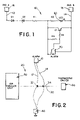
- FIG. 1 is a schematic diagram of the two wire alarm device of the present invention that senses an open circuit condition
- FIG. 2 is a basic wiring diagram illustrating an example installation of the alarm device to the thermostat circuit of an HVAC system in conjunction with a water sensitive float switch.
- the alarm device of the present invention is shown connected to the control circuit of an HVAC system 20 , wherein the alarm device is generally indicated as 10 .
- the alarm device 10 is shown connected to the control circuit of an HVAC system in FIG. 2 for purposes of example. It is recognized that use of the alarm device 10 is not limited to an HVAC system but, rather, the alarm device 10 may be used in any circuit for the purpose of providing an audible and/or visual alert to the change in status of the circuit from a normally closed circuit condition to an open circuit condition.
- the alarm device can be used in an HVAC system circuit, such as in FIG. 2 , for providing an audible and/or visual alert to the existence of a problem, such as a drain occlusion or clog, which is causing a high liquid level condition, overflow or flood.
- the alarm device 10 provides an electronic signal and/or an audible and/or visual alert to the homeowner or building occupant that power to the system (e.g. HVAC system) has been interrupted due to a high level liquid condition resulting from an occlusion or other abnormality in the drainage assembly.
- the system e.g. HVAC system
- the alarm device 10 uses two connecting wires 12 , 14 for connecting the alarm device 10 to the circuit 30 .
- the wires 12 , 14 connect in series with float switch 40 along the single conductor connecting between the thermostat switch 50 and the air handler unit 60 of the HVAC system 20 .
- the non-polarized circuitry of the alarm device 10 allows for reverse connection of the wires 12 , 14 .
- the wires 12 , 14 of the alarm device are each connected to a different one of the terminal connection points 32 , 34 where the float switch connects to the thermostat circuit.
- the connection of wires 12 , 14 to points 32 , 34 may be reversed while still allowing full function of the alarm device 10 . This allows for ease of connection of the wires 12 , 14 to the circuit without the possibility of error, as long as both wires 12 , 14 are not connected to the same point.
- the alarm device In the event the circuit changes from a closed condition to an open condition (e.g. due to operation of a switch in the circuit), the alarm device is energized to send an electronic signal and/or actuate either or both an audible and visual alarm indicator.
- the audible alarm indicator is a piezo electric buzzer 70 and the visual alarm indicator is a flashing LED 80 .
- the circuitry of the alarm device 10 includes a piezo electric buzzer 70 and flashing red LED 80 .
- the circuitry of the alarm may also contain an electronic signal transmitter or generator. These components, along with resisters R 1 –R 5 and diodes D 1 and D 2 are housed on a PC board that may be enclosed within a case.
- the wires 12 , 14 are connected to the circuitry and extend from the PC board. The terminal ends of the wires 12 , 14 may be provided with connecter elements 16 , 18 for ease of connection to the terminal connection points 32 , 34 along the circuit.
Landscapes
- Engineering & Computer Science (AREA)
- Chemical & Material Sciences (AREA)
- Combustion & Propulsion (AREA)
- Mechanical Engineering (AREA)
- General Engineering & Computer Science (AREA)
- Physics & Mathematics (AREA)
- General Physics & Mathematics (AREA)
- Human Computer Interaction (AREA)
- Electromagnetism (AREA)
- Alarm Systems (AREA)
Abstract
Description
Claims (13)
Priority Applications (1)
| Application Number | Priority Date | Filing Date | Title |
|---|---|---|---|
| US10/973,510 US7199722B2 (en) | 2004-06-19 | 2004-10-26 | Two wire alarm |
Applications Claiming Priority (2)
| Application Number | Priority Date | Filing Date | Title |
|---|---|---|---|
| US58133804P | 2004-06-19 | 2004-06-19 | |
| US10/973,510 US7199722B2 (en) | 2004-06-19 | 2004-10-26 | Two wire alarm |
Publications (2)
| Publication Number | Publication Date |
|---|---|
| US20050280548A1 US20050280548A1 (en) | 2005-12-22 |
| US7199722B2 true US7199722B2 (en) | 2007-04-03 |
Family
ID=35480048
Family Applications (1)
| Application Number | Title | Priority Date | Filing Date |
|---|---|---|---|
| US10/973,510 Expired - Fee Related US7199722B2 (en) | 2004-06-19 | 2004-10-26 | Two wire alarm |
Country Status (1)
| Country | Link |
|---|---|
| US (1) | US7199722B2 (en) |
Families Citing this family (1)
| Publication number | Priority date | Publication date | Assignee | Title |
|---|---|---|---|---|
| TWM368834U (en) * | 2009-05-06 | 2009-11-11 | Inventec Appliances Corp | Keyboard module and electronic device with the same |
Citations (2)
| Publication number | Priority date | Publication date | Assignee | Title |
|---|---|---|---|---|
| US4740861A (en) * | 1986-12-05 | 1988-04-26 | Advance Transformer Company | Thermal protection device for a dual input voltage lamp transformer/ballast apparatus |
| US5655561A (en) * | 1995-11-27 | 1997-08-12 | Wendel; A. Christopher | Wireless system for detecting and stopping water leaks |
-
2004
- 2004-10-26 US US10/973,510 patent/US7199722B2/en not_active Expired - Fee Related
Patent Citations (2)
| Publication number | Priority date | Publication date | Assignee | Title |
|---|---|---|---|---|
| US4740861A (en) * | 1986-12-05 | 1988-04-26 | Advance Transformer Company | Thermal protection device for a dual input voltage lamp transformer/ballast apparatus |
| US5655561A (en) * | 1995-11-27 | 1997-08-12 | Wendel; A. Christopher | Wireless system for detecting and stopping water leaks |
Also Published As
| Publication number | Publication date |
|---|---|
| US20050280548A1 (en) | 2005-12-22 |
Similar Documents
| Publication | Publication Date | Title |
|---|---|---|
| CA2484960C (en) | Status indicator | |
| US10323857B2 (en) | Coupling harness for HVAC mini-split system | |
| US4969179A (en) | Telephone line monitoring circuit for providing a visual and auditory signal if the telephone line becomes inoperative | |
| US7199722B2 (en) | Two wire alarm | |
| US20170201085A1 (en) | Smart output protector | |
| CN101666843B (en) | Wireless detection device and system for grounding mechanism of workstation operators | |
| US7032325B2 (en) | Electronic control device for gas dryer | |
| US6992579B2 (en) | Burglar alarm system having reduced wiring | |
| JP2003041633A (en) | Antifreeze device | |
| JPS6142121Y2 (en) | ||
| US7423544B2 (en) | Method of selecting operation in a line-powered module | |
| US7986226B2 (en) | Remote output system and method | |
| JP2002365116A (en) | Gas meter control device | |
| JP2555503Y2 (en) | Interface for disaster prevention sensor | |
| JPS5981793A (en) | Receiving responder for security facilities | |
| KR970019262A (en) | Method and system of automatic control of apartments | |
| WO2006016830A1 (en) | Address micromodule (variants) | |
| GB2175722A (en) | Security systems | |
| JPH10208180A (en) | Signal transmitting method | |
| JPS6017596A (en) | Alarm display for gas breaking safety device | |
| KR20020014492A (en) | Apparatus for information display | |
| JPS58211298A (en) | Gas leakage alarm system | |
| JPS62181066A (en) | Apparatus for confirming gas blocking mode | |
| GB2349255A (en) | Alarm apparatus | |
| JPH08235998A (en) | Vibration response breaker |
Legal Events
| Date | Code | Title | Description |
|---|---|---|---|
| AS | Assignment |
Owner name: MSD RESEARCH, INC., FLORIDA Free format text: ASSIGNMENT OF ASSIGNORS INTEREST;ASSIGNORS:OAKNER, STUART;BRANNICK, MARK T.;BRANNICK, DONNA ELLEN OAKNER;REEL/FRAME:020762/0360 Effective date: 20080328 |
|
| FPAY | Fee payment |
Year of fee payment: 4 |
|
| AS | Assignment |
Owner name: THE RECTORSEAL CORPORATION, TEXAS Free format text: ASSIGNMENT OF ASSIGNORS INTEREST;ASSIGNOR:MSD RESEARCH, INC.;REEL/FRAME:028081/0885 Effective date: 20080403 |
|
| FEPP | Fee payment procedure |
Free format text: PAT HOLDER NO LONGER CLAIMS SMALL ENTITY STATUS, ENTITY STATUS SET TO UNDISCOUNTED (ORIGINAL EVENT CODE: STOL); ENTITY STATUS OF PATENT OWNER: LARGE ENTITY |
|
| REMI | Maintenance fee reminder mailed | ||
| LAPS | Lapse for failure to pay maintenance fees | ||
| STCH | Information on status: patent discontinuation |
Free format text: PATENT EXPIRED DUE TO NONPAYMENT OF MAINTENANCE FEES UNDER 37 CFR 1.362 |
|
| STCH | Information on status: patent discontinuation |
Free format text: PATENT EXPIRED DUE TO NONPAYMENT OF MAINTENANCE FEES UNDER 37 CFR 1.362 |
|
| FP | Lapsed due to failure to pay maintenance fee |
Effective date: 20150403 |