US7191663B2 - Testing apparatus and method of deriving Young's modulus from tensile stress/strain relationships - Google Patents
Testing apparatus and method of deriving Young's modulus from tensile stress/strain relationships Download PDFInfo
- Publication number
- US7191663B2 US7191663B2 US10/734,873 US73487303A US7191663B2 US 7191663 B2 US7191663 B2 US 7191663B2 US 73487303 A US73487303 A US 73487303A US 7191663 B2 US7191663 B2 US 7191663B2
- Authority
- US
- United States
- Prior art keywords
- specimen
- tester
- cement
- mold
- stress
- Prior art date
- Legal status (The legal status is an assumption and is not a legal conclusion. Google has not performed a legal analysis and makes no representation as to the accuracy of the status listed.)
- Expired - Lifetime, expires
Links
- 238000012360 testing method Methods 0.000 title abstract description 63
- 238000000034 method Methods 0.000 title description 14
- 239000004568 cement Substances 0.000 claims abstract description 73
- 238000006073 displacement reaction Methods 0.000 claims description 7
- 241001274660 Modulus Species 0.000 claims 1
- 239000000203 mixture Substances 0.000 abstract description 10
- 239000000463 material Substances 0.000 abstract description 7
- 238000005259 measurement Methods 0.000 abstract description 7
- 230000003068 static effect Effects 0.000 abstract description 4
- 238000010998 test method Methods 0.000 abstract description 4
- 230000003466 anti-cipated effect Effects 0.000 description 12
- 230000006835 compression Effects 0.000 description 8
- 238000007906 compression Methods 0.000 description 8
- 239000013013 elastic material Substances 0.000 description 7
- 238000002474 experimental method Methods 0.000 description 7
- 230000015572 biosynthetic process Effects 0.000 description 6
- 238000005755 formation reaction Methods 0.000 description 6
- 238000010586 diagram Methods 0.000 description 5
- 238000002955 isolation Methods 0.000 description 5
- 230000007774 longterm Effects 0.000 description 4
- 239000002002 slurry Substances 0.000 description 4
- 239000011398 Portland cement Substances 0.000 description 3
- 239000012530 fluid Substances 0.000 description 3
- 238000004519 manufacturing process Methods 0.000 description 3
- 230000008569 process Effects 0.000 description 3
- 238000007789 sealing Methods 0.000 description 3
- 238000007655 standard test method Methods 0.000 description 3
- 238000004458 analytical method Methods 0.000 description 2
- 238000004364 calculation method Methods 0.000 description 2
- 238000013461 design Methods 0.000 description 2
- 230000001066 destructive effect Effects 0.000 description 2
- 238000011161 development Methods 0.000 description 2
- 239000011396 hydraulic cement Substances 0.000 description 2
- 238000002347 injection Methods 0.000 description 2
- 239000007924 injection Substances 0.000 description 2
- 239000007788 liquid Substances 0.000 description 2
- 239000003921 oil Substances 0.000 description 2
- 238000009864 tensile test Methods 0.000 description 2
- 239000011399 Portland cement blend Substances 0.000 description 1
- 239000008186 active pharmaceutical agent Substances 0.000 description 1
- 230000008859 change Effects 0.000 description 1
- 230000008602 contraction Effects 0.000 description 1
- 230000001351 cycling effect Effects 0.000 description 1
- 230000009977 dual effect Effects 0.000 description 1
- 230000008030 elimination Effects 0.000 description 1
- 238000003379 elimination reaction Methods 0.000 description 1
- 239000013505 freshwater Substances 0.000 description 1
- 238000011065 in-situ storage Methods 0.000 description 1
- 230000001788 irregular Effects 0.000 description 1
- 230000007246 mechanism Effects 0.000 description 1
- 239000002480 mineral oil Substances 0.000 description 1
- 235000010446 mineral oil Nutrition 0.000 description 1
- 238000012986 modification Methods 0.000 description 1
- 230000004048 modification Effects 0.000 description 1
- 239000004570 mortar (masonry) Substances 0.000 description 1
- 239000002245 particle Substances 0.000 description 1
- 230000008439 repair process Effects 0.000 description 1
- 230000004044 response Effects 0.000 description 1
- 238000004088 simulation Methods 0.000 description 1
- 239000002893 slag Substances 0.000 description 1
- 239000007787 solid Substances 0.000 description 1
- 230000000638 stimulation Effects 0.000 description 1
- 229920002994 synthetic fiber Polymers 0.000 description 1
Images


Classifications
-
- G—PHYSICS
- G01—MEASURING; TESTING
- G01N—INVESTIGATING OR ANALYSING MATERIALS BY DETERMINING THEIR CHEMICAL OR PHYSICAL PROPERTIES
- G01N3/00—Investigating strength properties of solid materials by application of mechanical stress
- G01N3/08—Investigating strength properties of solid materials by application of mechanical stress by applying steady tensile or compressive forces
-
- G—PHYSICS
- G01—MEASURING; TESTING
- G01N—INVESTIGATING OR ANALYSING MATERIALS BY DETERMINING THEIR CHEMICAL OR PHYSICAL PROPERTIES
- G01N2203/00—Investigating strength properties of solid materials by application of mechanical stress
- G01N2203/0014—Type of force applied
- G01N2203/0016—Tensile or compressive
- G01N2203/0017—Tensile
-
- G—PHYSICS
- G01—MEASURING; TESTING
- G01N—INVESTIGATING OR ANALYSING MATERIALS BY DETERMINING THEIR CHEMICAL OR PHYSICAL PROPERTIES
- G01N2203/00—Investigating strength properties of solid materials by application of mechanical stress
- G01N2203/0058—Kind of property studied
- G01N2203/0069—Fatigue, creep, strain-stress relations or elastic constants
- G01N2203/0075—Strain-stress relations or elastic constants
-
- G—PHYSICS
- G01—MEASURING; TESTING
- G01N—INVESTIGATING OR ANALYSING MATERIALS BY DETERMINING THEIR CHEMICAL OR PHYSICAL PROPERTIES
- G01N2203/00—Investigating strength properties of solid materials by application of mechanical stress
- G01N2203/02—Details not specific for a particular testing method
- G01N2203/022—Environment of the test
- G01N2203/0222—Temperature
-
- G—PHYSICS
- G01—MEASURING; TESTING
- G01N—INVESTIGATING OR ANALYSING MATERIALS BY DETERMINING THEIR CHEMICAL OR PHYSICAL PROPERTIES
- G01N2203/00—Investigating strength properties of solid materials by application of mechanical stress
- G01N2203/02—Details not specific for a particular testing method
- G01N2203/022—Environment of the test
- G01N2203/023—Pressure
-
- G—PHYSICS
- G01—MEASURING; TESTING
- G01N—INVESTIGATING OR ANALYSING MATERIALS BY DETERMINING THEIR CHEMICAL OR PHYSICAL PROPERTIES
- G01N2203/00—Investigating strength properties of solid materials by application of mechanical stress
- G01N2203/02—Details not specific for a particular testing method
- G01N2203/022—Environment of the test
- G01N2203/0244—Tests performed "in situ" or after "in situ" use
- G01N2203/0246—Special simulation of "in situ" conditions, scale models or dummies
-
- G—PHYSICS
- G01—MEASURING; TESTING
- G01N—INVESTIGATING OR ANALYSING MATERIALS BY DETERMINING THEIR CHEMICAL OR PHYSICAL PROPERTIES
- G01N2203/00—Investigating strength properties of solid materials by application of mechanical stress
- G01N2203/02—Details not specific for a particular testing method
- G01N2203/025—Geometry of the test
- G01N2203/0252—Monoaxial, i.e. the forces being applied along a single axis of the specimen
-
- G—PHYSICS
- G01—MEASURING; TESTING
- G01N—INVESTIGATING OR ANALYSING MATERIALS BY DETERMINING THEIR CHEMICAL OR PHYSICAL PROPERTIES
- G01N2203/00—Investigating strength properties of solid materials by application of mechanical stress
- G01N2203/02—Details not specific for a particular testing method
- G01N2203/026—Specifications of the specimen
- G01N2203/0262—Shape of the specimen
- G01N2203/0268—Dumb-bell specimens
-
- G—PHYSICS
- G01—MEASURING; TESTING
- G01N—INVESTIGATING OR ANALYSING MATERIALS BY DETERMINING THEIR CHEMICAL OR PHYSICAL PROPERTIES
- G01N2203/00—Investigating strength properties of solid materials by application of mechanical stress
- G01N2203/02—Details not specific for a particular testing method
- G01N2203/026—Specifications of the specimen
- G01N2203/0298—Manufacturing or preparing specimens
-
- G—PHYSICS
- G01—MEASURING; TESTING
- G01N—INVESTIGATING OR ANALYSING MATERIALS BY DETERMINING THEIR CHEMICAL OR PHYSICAL PROPERTIES
- G01N2203/00—Investigating strength properties of solid materials by application of mechanical stress
- G01N2203/02—Details not specific for a particular testing method
- G01N2203/04—Chucks, fixtures, jaws, holders or anvils
- G01N2203/0464—Chucks, fixtures, jaws, holders or anvils with provisions for testing more than one specimen at the time
- G01N2203/047—Chucks, fixtures, jaws, holders or anvils with provisions for testing more than one specimen at the time in series
-
- G—PHYSICS
- G01—MEASURING; TESTING
- G01N—INVESTIGATING OR ANALYSING MATERIALS BY DETERMINING THEIR CHEMICAL OR PHYSICAL PROPERTIES
- G01N33/00—Investigating or analysing materials by specific methods not covered by groups G01N1/00 - G01N31/00
- G01N33/38—Concrete; Lime; Mortar; Gypsum; Bricks; Ceramics; Glass
- G01N33/383—Concrete or cement
Definitions
- the invention relates to testing methods and devices used for testing of the mechanical properties of cement including cement formed in wellbore environments.
- Cement is used in the casing and liners of a wellbore.
- the annular space between the casing/lining and the wellbore is filled with a predetermined quantity of a cement mixture, which after hardening retains the casing/liner in place in the wellbore.
- the cement mixture is pumped in at the top end of the casing or liner, down to the lower end thereof and out into and up the annular space on the outside of the casing/liner.
- cementing is employed during many phases of wellbore operations. For example, cement may be employed to cement or secure various casing strings and/or liners in a well. Cementing may also be used to repair casing and/or to achieve formation isolation. Additionally, cementing may be employed during well abandonment. Cement operations performed in wellbores under these high stress conditions present problems including difficulty in obtaining wellbore isolation and maintaining the mechanical integrity of the wellbore.
- cement is placed in the annulus created between the outside surface of a pipe string and the inside formation surface or wall of a wellbore in order to form a sheath to seal off fluid and/or solid production from formations penetrated by the wellbore.
- Cementing allows a wellbore to be selectively completed to allow production from, or injection into, one or more productive formations penetrated by the wellbore.
- Cement may be used for purposes including sealing off perforations, repairing casing leaks, plugging back or sealing off the lower section of a wellbore, or sealing the interior of a wellbore during abandonment operations.
- this isolation may be impacted by the particular stresses associated with the environment found in the wellbore during operations.
- the cement sheath may be exposed to stresses imposed by well operations such as perforating, hydraulic fracturing, or high temperature-pressure differentials.
- well cement compositions may be brittle when cured. These cement compositions may fail due to tensional and compressional stresses that are exerted on the set cement. These wellbore cements may be subjected to axial, shear, and compressional stresses. Relatively high temperatures may induce stress conditions and/or relatively high fluid pressures encountered inside cemented wellbore pipe strings during operations such as perforating, stimulation, injection, testing, or production. Moreover, stress conditions may be induced or aggravated by fluctuations or cycling in temperature or fluid pressures during similar operations.
- ASTM International has established the Standard Test Method for Flexural Strength of Concrete (Using Simple Beam With Center-Point Loading), Designation No. C 293-02.
- This test method purports to cover the determination of the flexural strength of concrete specimens by the use of a simple beam with center-point loading.
- R Modulus of rupture, psi, or MPa
- L span length, in., or mm
- b average width of the specimen at the fracture, in., or mm
- d average depth of the specimen a the fracture, in., or mm.
- This testing method only provides a modulus of rupture based on a perpendicular force being applied in surface ambient conditions. This testing method therefore fails to simulate the stresses encountered in the higher temperature and pressure conditions of the wellbore environment.
- This testing method only provides a flexural strength based on a vertical force being applied in surface ambient conditions to cause a total maximum load. This testing method therefore also fails to simulate the stresses encountered in the higher temperature and pressure conditions of the wellbore environment.
- the standards also include a testing method to measure splitting tensile strength.
- ASTM International Standard Test Method for Splitting Tensile Strength of Cylindrical Concrete Specimens, Designation No. C 496-96 provides for applying a diametrical compressive force along the length of a cylindrical concrete specimen until failure of the specimen.
- the loading induces tensile stresses on the plane containing the applied load and relatively high compressive stresses in the area around the applied load.
- Tensile failure occurs rather than compressive failure because the areas of load application are in a state of triaxial compression.
- this testing method only provides a tensile splitting strength based on a diametrical compressive force applied in surface ambient conditions. This testing method therefore fails to simulate the stresses encountered in the higher temperature and pressure conditions of the wellbore environment.
- each of these standards specifically instructs the creation of the specimens at a temperature and pressure that is similar to ambient surface conditions. None of these testing methods provides for the creation of samples under the temperature and pressure conditions found in a wellbore environment.
- the present invention offers a method of testing and a tester designed to test the stress and strain of cements under the temperature and pressures encountered by cement during use in wellbore environments. Using these stress and strain measurements, the Young's Modulus may be established for a material at the encountered temperature and pressure of the wellbore. Using this information, it is possible to derive a baseline for materials to be used in the wellbore environment.
- the present invention overcomes the problems associated with a conventional static Young's Modulus test, which is a time-consuming operation and is almost always done with the axial stress applied in a compressive mode-even though by most definitions, the Young's Modulus is a mechanical property pertaining to a materials response under tension.
- the following provides a means to combine static flexural/tensile strength testing and elasticity measurements of cements. Since most cements fail in the annulus of a well while under tension, or a combination of tension and compression, the ratio of axial stress to axial strain is an important factor when the axial stress was in tension, or a combination of tension and compression instead of just testing in compression.
- the present invention can generate Young's Modulus values for different cement compositions under stresses that are similar to the conditions occurring in an actual wellbore. The present invention allows the user to calculate the induced stresses that would occur if the different systems were used in a well, and thus develop better fit for purpose designs.
- the present invention includes the development of a testing apparatus that enables the user to first cure from a liquid state, and then determine the mechanical properties such as tensile strength of various cement slurry systems through non-ultrasonic, destructive methods, while maintaining confining pressure and temperature on the cement specimens for the duration of the curing and testing process. It is within the scope of the invention that the present apparatus allows for a more accurate testing of mechanical properties of oil and gas well cements to ensure the long term integrity of the cement sheath in a well bore for the entire operation life of a given well.
- this invention provides for an alternative means to accurately measure tensile strength of various cement systems under more realistic field conditions.
- the invention discloses an apparatus that allows for the elimination of data influenced by factors such as cooldown and depressurization of cured cement samples.
- Devices employing the testing techniques of the present invention may be fully automated in such a way that real-time stress versus strain plots can be generated prior to the determination of ultimate mechanical failure values. This would allow for an increase in both the quantity and the quality of data presented to the clients.
- the present invention provides for data consistency and reliability because a more uniform testing method for all cement systems can be employed and all test conditions and data recording may be microprocessor controlled.
- the multi-functionality of this apparatus allows the user to measure cement shear bond strength while maintaining confining pressure and temperature.
- FIG. 1 is a representative diagram of an embodiment of a modified ASTM testing device that can test tensile strength, or with a different fixture, can test flexural strength;
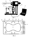
- FIG. 2 is a diagram showing a component of the present invention
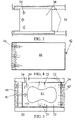
- FIG. 3 is a diagram showing a component of the present invention.
- FIG. 4 is a diagram showing a component of the present invention.
- FIG. 5 is top assembly view of an embodiment of the present invention showing the mold body and components
- FIG. 6 is a side assembly view of an embodiment of the present invention showing the mold body and components
- FIG. 7 is top assembly view of another embodiment of the present invention showing a plurality of mold bodies and components
- FIG. 8 is a front view of a view of an embodiment of the present invention showing the mold and components in a pressure cylinder;
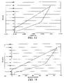
- FIG. 9 is a representative graph showing deflection versus time
- FIG. 10 is a representative graph showing stress versus deflection
- FIG. 11 is a representative graph showing Young's Modulus versus deflection
- FIG. 12 is a representative graph showing deflection versus time
- FIG. 13 is a representative graph showing stress versus deflection
- FIG. 14 is a representative graph showing stress versus microstrain
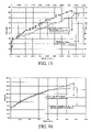
- FIG. 15 is a representative graph showing stress versus deflection
- FIG. 16 is a representative graph showing stress versus deflection.
- FIG. 17 is a representative graph showing stress versus deflection
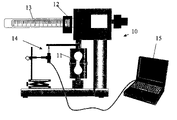
- FIG. 1 shows an embodiment of a flexural/tensile tester 10 , which provides a means to combine static flexural/tensile strength testing and elasticity measurements of cements. As configured in the Figure, the tester 10 is configured for testing tensile strength, but can be modified to test flexural strength.
- the tester 10 may utilize a beam loading system for automatic testing of cement specimens 11 in flexure and for tensile tests.
- This tester 10 has a traveling weight 12 , which is driven by electric motor across the beam 13 of the tester 10 to produce a constant rate of loading on the specimen 11 .
- the beam 13 has dual scales.
- the tester 10 is a flexural/tensile tester made by Gilson Company. Those skilled in the art will recognize that any tester capable of flexural and tensile testing is with the scope of the invention.
- the traveling weight 12 automatically stops upon specimen 11 failure and load is read directly from the applicable scale on the beam 13 .
- a sensor 14 is positioned in contact with the tester 10 such that the displacement may be measured and recorded.
- a computer 15 records the displacement measurements. This allows for calculations based not only of the force exerted at the time of failure of the specimen 11 , but the displacement at the time of failure.
- the tester 10 provides a constant rate of loading, so the computer 15 may also plot the displacement versus time and/or calculate the loading versus displacement for a variety of calculations.
- a tester 10 can be used to generate Young's Modulus values for different cement compositions under stresses that are similar to the conditions occurring in an actual wellbore in a pressurized configuration.
- the present invention includes the development of a testing apparatus that enables the user to first cure specimens 11 from a liquid state, and then determine the mechanical properties such as tensile strength and stress/strain relationships of various cement slurry systems through non-ultrasonic, destructive methods, while maintaining confining pressure and temperature on the cement specimens for the duration of the curing and testing process. It is within the scope of the invention that the present apparatus allows for a more accurate testing of mechanical properties of oil and gas well cements to ensure the long term integrity of the cement sheath in a well bore for the entire operation life of a given well.
- the cement specimen 11 is poured into a mold 19 having three sections: a mold stationary section 20 , a mold floating section 21 , and a mold follower section 22 .
- the mold 19 can be inserted into a pressure chamber capable of simulating the temperature and pressure found in the wellbore environment. Pressures up to 3,000 psi and temperatures up to 500° F. can be encountered in this environment. Those skilled in the art will recognize that the current invention is capable of being used at any pressure greater than atmospheric pressure and with a temperature range of about 32° F. to about 500° F.
- specimen 11 is poured or formed in a shape similar to the one depicted in FIG. 2 .
- the follower portion 22 of the mold 19 is bolted or otherwise attached to the follower 23 at bolt locations 24 .
- alignment pins 25 align the mold stationary section 20 , a mold floating section 21 , and a mold follower section 22 .
- the mold stationary section 20 is bolted to the mold base 30 , shown in FIG. 3 by base bolts 26 .
- follower 23 pulls the mold follower section 22 away from the mold stationary section 20 and the mold floating section 21 .
- the mold floating section 21 is designed to not exert any force of the specimen during testing.
- the mold stationary section 20 bolted to the mold base 30 , remains stationary during testing.
- the mold base 30 is shown in greater detail.
- the base bolts 26 which connect the mold base 30 to the stationary section 20 of the mold 19 , are shown.
- the mold base 30 is anchored to railings 31 . As shown in greater detail below, these railings 31 are anchored to the testing vessel and do not allow any movement.
- FIG. 4 shows the cam 40 .
- Cam assembly bolt 41 secures the top and bottom plate of cam 40 .
- the cam 40 pushes against the follower 23 at a front edge 42 of the cam 40 .
- the cam 40 provides an equal force of pressure against the follower 23 , which is imparted on the specimen 11 via the follower section 22 of the mold 19 .
- the fully assembled mold is shown in FIG. 5 .
- the cement specimen 11 is in the mold stationary section 20 , the mold floating section 21 , and the mold follower section 22 .
- the follower portion 22 is bolted or otherwise attached to the follower 23 at bolt locations 24 .
- Alignment pins 25 align the mold stationary section 20 , the mold floating section 21 , and the mold follower section 22 .
- the mold stationary section 20 is bolted to the mold base 30 , shown in FIG. 3 by base bolts 26 .
- This assembly view shows how the follower 23 can pulls the mold follower section 22 away from the mold stationary section 20 and the mold floating section 21 during testing.
- the base bolts 26 hold the stationary portion 20 in place as the follower 23 is pushed at the front edge 40 of the cam 40 .
- Cam assembly bolts 41 bolt the cam 40 .
- the mold stationary section 20 , the mold floating section 21 , and the mold follower section 22 are shown such that the mold follower section 22 is attached to the follower 23 by bolt 24 .
- the mold stationary section 20 is bolted to the mold base 30 base bolt 26 .
- Cam 40 pushes follower 23 , which in turn pulls the mold follower section 22 .
- FIG. 7 a plurality of testers are shown connected to the railing 31 within a pressure chamber 80 , which is used to simulate the temperature and pressure encountered in the wellbore.
- Piston 70 is disposed through cover 75 of the pressure chamber 80 .
- the piston 70 is moved by a short stroke hydraulic ram 74 or similar device.
- Precision linear transducers 71 , 72 are positioned on opposite sides of the piston 70 to ensure even travel of the piston 70 in to the pressure chamber 80 and to measure the displacement of the cam.
- a load cell 73 is disposed therein to measure to the amount of force applied by the ram 74 .
- thermocouple 76 and a pressure transducer 77 are connected to the pressure chamber 80 .
- Data from the precision linear transducers 71 , 72 , the thermocouple 76 , and the pressure transducer 77 are provided to a data acquisition unit 78 .
- Cement specimens 11 are placed in molds 30 within the pressure chamber 80 .
- a pressure medium 79 such as fresh water or mineral oil, is introduced to pressurize the system to the temperature and pressure levels that would be encountered in a wellbore environment.
- the cement specimens 11 are allowed to cure at these temperatures and pressures, as each would under wellbore conditions. Once cured, each specimen 11 is tested using the ram 74 to push the piston 70 such that each specimen 11 is sequentially stressed until failure.
- the piston pushes the first cam until the cement specimen 11 fails.
- the data acquisition unit 78 constantly monitors the precision linear transducers 71 , 72 , the thermocouple 76 , and the pressure transducer 77 , collecting data throughout the process. It is important to arrange each mold with enough axial distance such that the failure of each cement specimen will not cause the next follower to be bumped with a breaking force. By axially spacing the cams such that the first specimen fails, the piston ushers the cam forward to smoothly interface with the next cam. The next sample may be stretched in a sequential fashion.
- FIG. 8 shows a cross-sectional view of the pressure chamber 80 .
- the pressurizing medium 79 surrounds the testing apparatus.
- the rails 31 are connected the mold base 30 , wherein the pulled portion of the mold 22 is shown on top of the mold base 30 .
- the cam 40 is shown above and below the mold base 30 . This arrangement shows how the cam 40 urges the pulled portion of the mold 22 toward the viewer, thus stressing the cement specimen in the mold until failure.
- the deflection versus time graph in FIG. 9 shows the consistency of the deflection of the samples prior to failure.
- the peaks of the graphs are very similar and the time to failure of the three samples has a similar width on the X-axis.
- FIG. 10 shows the flexural stress (psi) versus the deflection (inches) for one of these samples.
- the linear increase of deflection as the stress increased shows the consistency of the results.
- the graph shows the flattening the Young's modulus as the sample's deflection nears the failure point.
- FIG. 11 Two additional samples are shown in FIG. 11 in a tensile strength test. Using the same slurry, a maximum cycle load of 3900 N (878 psi) with an actual failure load of 4725 N (1064 psi) was applied. Again, the consistency of the shape of the peaks and width of the results on the X-axis show the preciseness of the tester in this analysis.
- the graph in FIG. 12 shows the tensile stress versus the deflection of the sample under tension only. This is in comparison with FIG. 13 that shows the tensile strength test of the stress versus the microstrain.
- Calport H cement was mixed at 16.5 ppg and cured for about 48 hours at atmospheric temperature and pressure.
- the following table depicts the three specimens as stress using the above-disclosed tester was applied on each specimen. The deflection was measured using the precision linear transducers listed above.
- the first and third specimens bear similar results, namely 155.927 psi with 0.0033 inches deflection and 0.0047 inches deflection, respectively while the second specimen bears 167.478 psi and 0.0042 inches deflection.
- the data for the second and third specimens have been graphed in FIG. 15 . The closeness of this data indicates the consistency of the testing technique. It is envisioned that this consistency will be seen in pressurized experiments.
- the first specimen bore 381.276 psi and 0.0146 inches deflection while the second specimen boar 435.745 psi and 0.0136 inches deflection.
- the data for the first and second specimens have been graphed in FIG. 16 .
- the closeness of this data indicates the consistency of the testing technique. It is envisioned that this consistency will be seen in pressurized experiments.
- Calport G cement was mixed at 15.8 ppg and cured for about 48 hours at 130° F. and atmospheric pressure. Two specimens were tested.
- the first specimen bore 397.62 psi and 0.0187 inches deflection while the second specimen boar 446.638 psi 0.018 inches deflection.
- the data for the first and second specimens have been graphed in FIG. 17 . Again, the closeness of this data indicates the consistency of the testing technique. It is envisioned that this consistency will be seen in pressurized experiments.
- suitable hydraulic cement types that may be employed, alone or in mixtures, for wellbore cementing include Portland cements, and more particularly ASTM Type I, II, III, IV and/or V Portland cements, and API Class A, B, C, G and/or H Portland cements, pozzolan cements, Portland cement blends, commercial lightweight cements, slag cements, and microfine cements.
- Any natural or synthetic material that is substantially elastic, and more particularly that is selected to be substantially elastic under in situ cementing conditions may be employed.
- Such materials may be employed in particulate form, and may have individual particles of material may have shapes such as beaded, regular, or irregular shapes, or mixtures thereof.
- substantially elastic materials include, but are not limited to, those elastic materials having a Young's modulus of elasticity between about 500 psi and about 2,600,000 psi at anticipated cementing conditions, alternatively between about 500 psi and about 2,000,000 psi at anticipated cementing conditions, alternatively between about 5,000 psi and about 2,000,000 psi at anticipated cementing conditions, alternatively between about 5,000 psi and about 500,000 psi at anticipated cementing conditions, alternatively between about 5,000 psi and 200,000 psi at anticipated cementing conditions, and further alternatively between about 7,000 and 150,000 psi at anticipated cementing conditions.
- substantially elastic materials include, but are not limited to, those elastic materials having a Young's modulus of elasticity between about 500 psi and about 30,000,000 psi at anticipated cementing conditions, alternatively between about 2,000,000 psi and about 30,000,000 psi at anticipated cementing conditions, alternatively between about 2,000,000 psi and about 10,000,000 psi at anticipated cementing conditions, alternatively between about 5,000 psi and about 5,000,000 psi at anticipated cementing conditions, and alternatively between about 7,000 psi and about 1,500,000 psi at anticipated cementing conditions.
- substantially elastic materials include, but are not limited to, those elastic materials having a Young's modulus of elasticity between about 500 psi and about 150,000 psi at anticipated cementing conditions.
- substantially elastic materials may also have values of Young's modulus of elasticity that are greater than or lesser than those values given in the ranges above.
Landscapes
- Physics & Mathematics (AREA)
- Health & Medical Sciences (AREA)
- Life Sciences & Earth Sciences (AREA)
- Chemical & Material Sciences (AREA)
- Analytical Chemistry (AREA)
- Biochemistry (AREA)
- General Health & Medical Sciences (AREA)
- General Physics & Mathematics (AREA)
- Immunology (AREA)
- Pathology (AREA)
- Investigating Strength Of Materials By Application Of Mechanical Stress (AREA)
Abstract
Description
R=3 PL/2bd 2 (1)
where:
S f=0.0028 P (2)
where
T=2P/(Πld) (3)
where:
| TABLE 1 |
| Calport H Stress v. Deflection Testing |
| Time | Deflect 1 | Stress 1 | Deflect 2 | Stress 2 | Deflect 3 | Stress 3 |
| (sec) | (inches) | (psi) | (inches) | (psi) | (inches) | (psi) |
| 0 | 0 | 0 | 0 | 0 | 0 | 0 |
| 1.002 | 0 | 0 | 0 | 0 | 0 | 0 |
| 1.998 | 0 | 0 | 0 | 0 | 0 | −5.775096 |
| 3.000 | 0 | 0 | 0 | 0 | 0 | 0 |
| 4.002 | 0 | 0 | 0 | 0 | 0 | 0 |
| 4.998 | 0 | 0 | 0 | 0 | 0 | 0 |
| 6.000 | 0 | 0 | 0 | 0 | 0 | 5.775096 |
| 7.000 | 0 | 5.775096 | 0 | 11.550184 | 0 | 5.775096 |
| 8.000 | 0 | 5.775096 | 0 | 11.550184 | 0 | 11.550184 |
| 9.000 | 0 | 11.550192 | 0 | 11.550184 | 0 | 11.550184 |
| 10.000 | 0 | 17.32528 | 0 | 17.32528 | 0 | 17.32528 |
| 11.000 | 0 | 17.32528 | 0 | 17.32528 | 0 | 17.32528 |
| 12.000 | 0 | 23.100376 | 0 | 23.100376 | 0 | 23.100376 |
| 13.000 | 0 | 23.100376 | 0 | 28.875464 | 0.0001 | 28.875472 |
| 14.000 | 0 | 28.875472 | 0 | 28.875464 | 0 | 28.875472 |
| 15.000 | 0 | 28.875472 | 0 | 28.875464 | 0.0001 | 28.875472 |
| 16.000 | 0 | 28.875472 | 0 | 34.6505616 | 0.0001 | 34.65056 |
| 17.000 | 0 | 34.650568 | 0 | 34.6505616 | 0.0001 | 34.65056 |
| 18.000 | 0 | 34.650568 | 0 | 40.425656 | 0.0001 | 34.65056 |
| 19.000 | 0 | 34.650568 | 0 | 40.425656 | 0.0001 | 34.65056 |
| 20.000 | 0 | 40.425656 | 0 | 40.425656 | 0.0001 | 40.4256576 |
| 21.000 | 0 | 40.425656 | 0 | 46.2007504 | 0.0001 | 46.200752 |
| 22.000 | 0 | 40.425656 | 0 | 46.2007504 | 0.0001 | 46.200752 |
| 23.000 | 0 | 46.2007536 | 0.0001 | 51.975848 | 0.0001 | 51.9758464 |
| 24.000 | 0.0001 | 46.2007536 | 0.0001 | 51.975848 | 0.0001 | 57.750944 |
| 25.000 | 0.0001 | 51.975848 | 0.0001 | 57.750936 | 0.0001 | 57.750944 |
| 26.000 | 0.0001 | 51.975848 | 0.0001 | 57.750936 | 0.0005 | 63.526032 |
| 27.000 | 0.0001 | 57.7509424 | 0.0001 | 63.526032 | 0.0006 | 69.301128 |
| 28.000 | 0.0001 | 57.7509424 | 0.0001 | 63.526032 | 0.0008 | 69.301128 |
| 29.000 | 0.0001 | 63.52604 | 0.0004 | 63.526032 | 0.0009 | 69.301128 |
| 30.000 | 0.0001 | 63.52604 | 0.0004 | 69.301128 | 0.001 | 75.076224 |
| 31.000 | 0.0001 | 69.301128 | 0.0005 | 69.301128 | 0.0012 | 75.076224 |
| 32.000 | 0.0001 | 75.076224 | 0.0006 | 75.076224 | 0.0013 | 80.85132 |
| 33.000 | 0.0001 | 75.076224 | 0.0007 | 75.076224 | 0.0014 | 80.85132 |
| 34.000 | 0.0004 | 75.076224 | 0.0008 | 80.851312 | 0.0016 | 86.626408 |
| 35.000 | 0.0004 | 75.076224 | 0.0009 | 86.626408 | 0.0017 | 92.401504 |
| 36.000 | 0.0005 | 80.85132 | 0.001 | 92.401504 | 0.0018 | 92.401504 |
| 37.000 | 0.0006 | 80.85132 | 0.0011 | 92.401504 | 0.002 | 98.1766 |
| 38.000 | 0.0007 | 86.626416 | 0.0013 | 92.401504 | 0.0021 | 98.1766 |
| 39.000 | 0.0008 | 92.401504 | 0.0013 | 98.1766 | 0.0023 | 103.951696 |
| 40.000 | 0.001 | 92.401504 | 0.0015 | 98.1766 | 0.0024 | 103.951696 |
| 41.000 | 0.001 | 98.1766 | 0.0015 | 103.951696 | 0.0025 | 103.951696 |
| 42.000 | 0.0012 | 103.951696 | 0.0017 | 103.951696 | 0.0026 | 109.726792 |
| 43.000 | 0.0013 | 103.951696 | 0.0017 | 109.726784 | 0.0027 | 115.50188 |
| 44.000 | 0.0013 | 103.951696 | 0.0019 | 109.726784 | 0.0029 | 115.50188 |
| 45.000 | 0.0015 | 109.726792 | 0.0019 | 115.50188 | 0.003 | 121.276976 |
| 46.000 | 0.0016 | 109.726792 | 0.0021 | 115.50188 | 0.0031 | 121.276976 |
| 47.000 | 0.0017 | 115.501888 | 0.0021 | 121.276984 | 0.0033 | 121.276976 |
| 48.000 | 0.0019 | 121.276976 | 0.0022 | 121.276984 | 0.0034 | 127.05208 |
| 49.000 | 0.002 | 121.276976 | 0.0024 | 127.052104 | 0.0035 | 127.05208 |
| 50.000 | 0.0021 | 127.052072 | 0.0024 | 132.827144 | 0.0037 | 138.60224 |
| 51.000 | 0.0022 | 127.052072 | 0.0026 | 132.827144 | 0.0038 | 138.60224 |
| 52.000 | 0.0023 | 127.052072 | 0.0027 | 132.827144 | 0.004 | 138.60224 |
| 53.000 | 0.0025 | 132.827176 | 0.0028 | 138.602264 | 0.0041 | 138.60224 |
| 54.000 | 0.0025 | 132.827176 | 0.0029 | 138.602264 | 0.0042 | 144.37736 |
| 55.000 | 0.0027 | 144.377336 | 0.0031 | 144.377384 | 0.0043 | 150.15248 |
| 56.000 | 0.0028 | 144.377336 | 0.0031 | 150.152424 | 0.0044 | 155.92752 |
| 57.000 | 0.003 | 144.377336 | 0.0033 | 150.152424 | 0.0045 | 155.92752 |
| 58.000 | 0.0031 | 144.377336 | 0.0034 | 150.152424 | 0.0047 | 155.92752 |
| 59.000 | 0.0031 | 150.152456 | 0.0036 | 155.927544 | ||
| 60.000 | 0.0033 | 155.927576 | 0.0036 | 155.927544 | ||
| 61.000 | 0.0038 | 161.702664 | ||||
| 62.000 | 0.0039 | 161.702664 | ||||
| 63.000 | 0.0041 | 167.477704 | ||||
| 64.000 | 0.0042 | 167.477704 | ||||
| TABLE 2 |
| Calport G Stress v. Deflection Testing |
| Time | Deflect 2 | Stress 2 | Stress 1 | |
| (sec) | (inches) | (psi) | Deflect 1 | (psi) |
| 1 | 0 | 21.787232 | 0 | 21.787232 |
| 2 | 0 | 21.787232 | 0 | 21.787232 |
| 3 | 0 | 21.787232 | 0 | 21.787232 |
| 4 | 0 | 21.787232 | 0 | 21.787232 |
| 5 | 0 | 21.787232 | 0 | 21.787232 |
| 6 | 0 | 21.787232 | 0 | 21.787232 |
| 7 | 0 | 21.787232 | 0 | 21.787232 |
| 8 | 0 | 21.787232 | 0 | 21.787232 |
| 9 | 0 | 21.787232 | 0 | 21.787232 |
| 10 | 0 | 27.23404 | 0 | 21.787232 |
| 11 | 0 | 32.680856 | 0 | 27.23404 |
| 12 | 0 | 32.680856 | 0 | 27.23404 |
| 13 | 0 | 38.127664 | 0 | 32.680856 |
| 14 | 0 | 43.574472 | 0 | 38.127664 |
| 15 | 0 | 43.574472 | 0 | 38.127664 |
| 16 | 0 | 43.574472 | 0 | 43.574472 |
| 17 | 0 | 49.02128 | 0 | 43.574472 |
| 18 | 0 | 49.02128 | 0 | 43.574472 |
| 19 | 0 | 49.02128 | 0 | 43.574472 |
| 20 | 0 | 54.468088 | 0 | 49.02128 |
| 21 | 0 | 59.914896 | 0 | 54.468088 |
| 22 | 0 | 59.914896 | 0 | 54.468088 |
| 23 | 0 | 59.914896 | 0 | 59.914896 |
| 24 | 0 | 65.361704 | 0 | 59.914896 |
| 25 | 0 | 65.361704 | 0 | 59.914896 |
| 26 | 0 | 70.808512 | 0 | 65.361704 |
| 27 | 0 | 70.808512 | 0 | 65.361704 |
| 28 | 0 | 76.25532 | 0 | 70.808512 |
| 29 | 0 | 76.25532 | 0 | 70.808512 |
| 30 | 0 | 81.70216 | 0 | 76.25532 |
| 31 | 0 | 81.70216 | 0 | 76.25532 |
| 32 | 0 | 81.70216 | 0 | 81.70216 |
| 33 | 0 | 87.14896 | 0 | 81.70216 |
| 34 | 0 | 87.14896 | 0 | 87.14896 |
| 35 | 0 | 92.59576 | 0 | 87.14896 |
| 36 | 0 | 98.04256 | 0 | 92.59576 |
| 37 | 0 | 98.04256 | 0 | 92.59576 |
| 38 | 0 | 98.04256 | 0 | 98.04256 |
| 39 | 0 | 103.48936 | 0 | 98.04256 |
| 40 | 0 | 103.48936 | 0 | 98.04256 |
| 41 | 0 | 108.93616 | 0 | 98.04256 |
| 42 | 0.0001 | 108.93616 | 0 | 103.48936 |
| 43 | 0.0001 | 114.38296 | 0 | 103.48936 |
| 44 | 0.0001 | 114.38296 | 0 | 108.93616 |
| 45 | 0.0001 | 119.82976 | 0 | 108.93616 |
| 46 | 0.0001 | 119.82976 | 0 | 114.38296 |
| 47 | 0.0001 | 125.27656 | 0 | 114.38296 |
| 48 | 0.0001 | 125.27656 | 0 | 119.82976 |
| 49 | 0.0004 | 130.72344 | 0 | 119.82976 |
| 50 | 0.0005 | 136.17024 | 0 | 119.82976 |
| 51 | 0.0005 | 136.17024 | 0 | 125.27656 |
| 52 | 0.0005 | 136.17024 | 0 | 125.27656 |
| 53 | 0.0006 | 141.61704 | 0.0001 | 130.72344 |
| 54 | 0.0007 | 147.06384 | 0.0001 | 136.17024 |
| 55 | 0.0007 | 147.06384 | 0.0001 | 136.17024 |
| 56 | 0.0008 | 152.51064 | 0.0001 | 141.61704 |
| 57 | 0.0009 | 152.51064 | 0.0009 | 147.06384 |
| 58 | 0.0009 | 157.95744 | 0.001 | 147.06384 |
| 59 | 0.001 | 157.95744 | 0.001 | 152.51064 |
| 60 | 0.001 | 163.40424 | 0.001 | 152.51064 |
| 61 | 0.0011 | 163.40424 | 0.001 | 152.51064 |
| 62 | 0.0011 | 168.85104 | 0.001 | 157.95744 |
| 63 | 0.0012 | 168.85104 | 0.001 | 157.95744 |
| 64 | 0.0013 | 174.29784 | 0.001 | 163.40424 |
| 65 | 0.0013 | 174.29784 | 0.0013 | 163.40424 |
| 66 | 0.0014 | 179.74472 | 0.0013 | 168.85104 |
| 67 | 0.0015 | 179.74472 | 0.0013 | 174.29784 |
| 68 | 0.0016 | 185.19152 | 0.0013 | 174.29784 |
| 69 | 0.0017 | 185.19152 | 0.0014 | 174.29784 |
| 70 | 0.0017 | 185.19152 | 0.0014 | 179.74472 |
| 71 | 0.0018 | 185.19152 | 0.0015 | 185.19152 |
| 72 | 0.0019 | 190.63832 | 0.0015 | 185.19152 |
| 73 | 0.0019 | 190.63832 | 0.0016 | 185.19152 |
| 74 | 0.002 | 196.08512 | 0.0016 | 185.19152 |
| 75 | 0.0021 | 196.08512 | 0.0017 | 185.19152 |
| 76 | 0.0022 | 201.53192 | 0.0017 | 190.63832 |
| 77 | 0.0023 | 201.53192 | 0.0018 | 196.08512 |
| 78 | 0.0023 | 206.97872 | 0.0019 | 196.08512 |
| 79 | 0.0024 | 206.97872 | 0.002 | 201.53192 |
| 80 | 0.0025 | 212.42552 | 0.002 | 201.53192 |
| 81 | 0.0026 | 212.42552 | 0.0021 | 201.53192 |
| 82 | 0.0027 | 212.42552 | 0.0022 | 206.97872 |
| 83 | 0.0028 | 217.87232 | 0.0022 | 212.42552 |
| 84 | 0.0028 | 217.87232 | 0.0023 | 212.42552 |
| 85 | 0.0029 | 223.3192 | 0.0023 | 212.42552 |
| 86 | 0.003 | 223.3192 | 0.0025 | 217.87232 |
| 87 | 0.0031 | 228.766 | 0.0025 | 217.87232 |
| 88 | 0.0032 | 228.766 | 0.0026 | 223.3192 |
| 89 | 0.0032 | 228.766 | 0.0027 | 223.3192 |
| 90 | 0.0033 | 234.2128 | 0.0027 | 223.3192 |
| 91 | 0.0034 | 234.2128 | 0.0028 | 228.766 |
| 92 | 0.0035 | 239.6596 | 0.0029 | 228.766 |
| 93 | 0.0036 | 239.6596 | 0.003 | 234.2128 |
| 94 | 0.0037 | 239.6596 | 0.0031 | 234.2128 |
| 95 | 0.0038 | 245.1064 | 0.0032 | 239.6596 |
| 96 | 0.0039 | 250.5532 | 0.0032 | 239.6596 |
| 97 | 0.0039 | 250.5532 | 0.0033 | 239.6596 |
| 98 | 0.0041 | 250.5532 | 0.0034 | 245.1064 |
| 99 | 0.0041 | 256 | 0.0035 | 250.5532 |
| 100 | 0.0042 | 256 | 0.0036 | 250.5532 |
| 101 | 0.0043 | 256 | 0.0037 | 250.5532 |
| 102 | 0.0044 | 261.4468 | 0.0038 | 256 |
| 103 | 0.0045 | 261.4468 | 0.0039 | 256 |
| 104 | 0.0046 | 266.8936 | 0.004 | 261.4468 |
| 105 | 0.0047 | 266.8936 | 0.004 | 261.4468 |
| 106 | 0.0048 | 266.8936 | 0.0042 | 266.8936 |
| 107 | 0.0049 | 272.3404 | 0.0042 | 266.8936 |
| 108 | 0.005 | 272.3404 | 0.0044 | 266.8936 |
| 109 | 0.0051 | 277.7872 | 0.0044 | 272.3404 |
| 110 | 0.0052 | 277.7872 | 0.0046 | 272.3404 |
| 111 | 0.0053 | 277.7872 | 0.0046 | 272.3404 |
| 112 | 0.0054 | 283.23408 | 0.0047 | 277.7872 |
| 113 | 0.0055 | 283.23408 | 0.0048 | 277.7872 |
| 114 | 0.0056 | 288.68088 | 0.0049 | 283.23408 |
| 115 | 0.0057 | 288.68088 | 0.005 | 283.23408 |
| 116 | 0.0058 | 294.12768 | 0.0051 | 288.68088 |
| 117 | 0.0059 | 294.12768 | 0.0052 | 288.68088 |
| 118 | 0.006 | 294.12768 | 0.0053 | 294.12768 |
| 119 | 0.0061 | 294.12768 | 0.0054 | 294.12768 |
| 120 | 0.0062 | 299.57448 | 0.0055 | 294.12768 |
| 121 | 0.0063 | 305.02128 | 0.0056 | 299.57448 |
| 122 | 0.0064 | 305.02128 | 0.0058 | 299.57448 |
| 123 | 0.0065 | 305.02128 | 0.0058 | 305.02128 |
| 124 | 0.0066 | 310.46808 | 0.006 | 305.02128 |
| 125 | 0.0067 | 310.46808 | 0.006 | 305.02128 |
| 126 | 0.0068 | 315.91488 | 0.0062 | 310.46808 |
| 127 | 0.0069 | 315.91488 | 0.0062 | 310.46808 |
| 128 | 0.007 | 315.91488 | 0.0064 | 315.91488 |
| 129 | 0.0071 | 321.36168 | 0.0064 | 315.91488 |
| 130 | 0.0072 | 326.80856 | 0.0067 | 315.91488 |
| 131 | 0.0073 | 326.80856 | 0.0067 | 321.36168 |
| 132 | 0.0074 | 326.80856 | 0.0069 | 326.80856 |
| 133 | 0.0075 | 326.80856 | 0.007 | 326.80856 |
| 134 | 0.0076 | 332.25536 | 0.0072 | 326.80856 |
| 135 | 0.0077 | 332.25536 | 0.0073 | 332.25536 |
| 136 | 0.0078 | 332.25536 | 0.0074 | 332.25536 |
| 137 | 0.0079 | 337.70216 | 0.0075 | 332.25536 |
| 138 | 0.008 | 343.14896 | 0.0076 | 337.70216 |
| 139 | 0.0081 | 343.14896 | 0.0078 | 337.70216 |
| 140 | 0.0082 | 348.59576 | 0.0079 | 343.14896 |
| 141 | 0.0083 | 348.59576 | 0.0081 | 348.59576 |
| 142 | 0.0084 | 348.59576 | 0.0083 | 348.59576 |
| 143 | 0.0086 | 348.59576 | 0.0085 | 348.59576 |
| 144 | 0.0087 | 348.59576 | 0.0086 | 348.59576 |
| 145 | 0.0088 | 348.59576 | 0.0088 | 348.59576 |
| 146 | 0.0089 | 348.59576 | 0.0093 | 348.59576 |
| 147 | 0.0091 | 354.04256 | 0.0093 | 348.59576 |
| 148 | 0.0092 | 359.48936 | 0.0097 | 354.04256 |
| 149 | 0.0093 | 359.48936 | 0.0098 | 354.04256 |
| 150 | 0.0094 | 364.93616 | 0.0102 | 359.48936 |
| 151 | 0.0096 | 364.93616 | 0.0104 | 359.48936 |
| 152 | 0.0097 | 364.93616 | 0.0107 | 364.93616 |
| 153 | 0.0098 | 370.38296 | 0.0111 | 364.93616 |
| 154 | 0.0099 | 370.38296 | 0.0114 | 364.93616 |
| 155 | 0.0101 | 370.38296 | 0.0119 | 364.93616 |
| 156 | 0.0102 | 375.82976 | 0.0125 | 370.38296 |
| 157 | 0.0103 | 375.82976 | 0.0126 | 370.38296 |
| 158 | 0.0104 | 381.27664 | 0.0134 | 370.38296 |
| 159 | 0.0106 | 381.27664 | 0.0136 | 375.82976 |
| 160 | 0.0107 | 386.72344 | 0.0142 | 381.27664 |
| 161 | 0.0109 | 386.72344 | 0.0146 | 381.27664 |
| 162 | 0.011 | 386.72344 | ||
| 163 | 0.0111 | 392.17024 | ||
| 164 | 0.0113 | 392.17024 | ||
| 165 | 0.0114 | 392.17024 | ||
| 166 | 0.0115 | 397.61704 | ||
| 167 | 0.0116 | 397.61704 | ||
| 168 | 0.0118 | 397.61704 | ||
| 169 | 0.0119 | 403.06384 | ||
| 170 | 0.012 | 403.06384 | ||
| 171 | 0.0121 | 408.51064 | ||
| 172 | 0.0122 | 408.51064 | ||
| 173 | 0.0124 | 408.51064 | ||
| 174 | 0.0125 | 413.95744 | ||
| 175 | 0.0126 | 413.95744 | ||
| 176 | 0.0126 | 419.40424 | ||
| 177 | 0.0128 | 419.40424 | ||
| 178 | 0.0129 | 419.40424 | ||
| 179 | 0.013 | 424.85104 | ||
| 180 | 0.0131 | 424.85104 | ||
| 181 | 0.0132 | 430.29792 | ||
| 182 | 0.0133 | 430.29792 | ||
| 183 | 0.0134 | 430.29792 | ||
| 184 | 0.0135 | 430.29792 | ||
| 185 | 0.0136 | 435.74464 | ||
| TABLE 3 |
| Second Calport G Stress v. Deflection Testing |
| Time | Deflection 2 | Stress 2 | Deflection 1 | Stress 1 |
| (sec) | (inches) | (psi) | (inches) | (psi) |
| 0 | 0.000 | 10.894 | 0.0000 | 21.79 |
| 1.000 | 0.000 | 10.894 | 0.0000 | 21.79 |
| 2.000 | 0.000 | 10.894 | 0.0000 | 21.79 |
| 3.000 | 0.000 | 16.340 | 0.0000 | 21.79 |
| 4.000 | 0.000 | 16.340 | 0.0000 | 21.79 |
| 5.000 | 0.000 | 16.340 | 0.0000 | 21.79 |
| 6.000 | 0.000 | 16.340 | 0.0000 | 21.79 |
| 7.000 | 0.000 | 21.787 | 0.0000 | 27.23 |
| 8.000 | 0.000 | 21.787 | 0.0000 | 27.23 |
| 9.000 | 0.000 | 21.787 | 0.0000 | 32.68 |
| 10.000 | 0.000 | 21.787 | 0.0000 | 38.13 |
| 11.000 | 0.000 | 27.234 | 0.0000 | 38.13 |
| 12.000 | 0.000 | 27.234 | 0.0000 | 43.57 |
| 13.000 | 0.000 | 27.234 | 0.0000 | 49.02 |
| 14.000 | 0.000 | 32.681 | 0.0000 | 49.02 |
| 15.000 | 0.000 | 38.128 | 0.0000 | 49.02 |
| 16.000 | 0.000 | 38.128 | 0.0000 | 54.47 |
| 17.000 | 0.001 | 43.574 | 0.0000 | 54.47 |
| 18.000 | 0.001 | 43.574 | 0.0000 | 59.91 |
| 19.000 | 0.001 | 49.021 | 0.0000 | 59.91 |
| 20.000 | 0.001 | 54.468 | 0.0000 | 59.91 |
| 21.000 | 0.001 | 59.915 | 0.0000 | 59.91 |
| 22.000 | 0.001 | 59.915 | 0.0000 | 65.36 |
| 23.000 | 0.001 | 65.362 | 0.0000 | 70.81 |
| 24.000 | 0.001 | 70.809 | 0.0000 | 76.26 |
| 25.000 | 0.001 | 70.809 | 0.0000 | 76.26 |
| 26.000 | 0.001 | 76.255 | 0.0000 | 76.26 |
| 27.000 | 0.001 | 81.702 | 0.0001 | 76.26 |
| 28.000 | 0.001 | 81.702 | 0.0001 | 81.70 |
| 29.000 | 0.001 | 81.702 | 0.0001 | 87.15 |
| 30.000 | 0.001 | 87.149 | 0.0001 | 87.15 |
| 31.000 | 0.001 | 87.149 | 0.0001 | 87.15 |
| 32.000 | 0.001 | 92.596 | 0.0001 | 92.60 |
| 33.000 | 0.001 | 98.043 | 0.0001 | 98.04 |
| 34.000 | 0.002 | 98.043 | 0.0001 | 98.04 |
| 35.000 | 0.002 | 103.489 | 0.0001 | 98.04 |
| 36.000 | 0.002 | 103.489 | 0.0001 | 98.04 |
| 37.000 | 0.002 | 108.936 | 0.0001 | 103.49 |
| 38.000 | 0.002 | 114.383 | 0.0001 | 108.94 |
| 39.000 | 0.002 | 114.383 | 0.0003 | 114.38 |
| 40.000 | 0.002 | 119.830 | 0.0004 | 114.38 |
| 41.000 | 0.002 | 119.830 | 0.0005 | 114.38 |
| 42.000 | 0.002 | 119.830 | 0.0006 | 119.83 |
| 43.000 | 0.002 | 119.830 | 0.0006 | 119.83 |
| 44.000 | 0.002 | 125.277 | 0.0007 | 125.28 |
| 45.000 | 0.002 | 130.723 | 0.0007 | 125.28 |
| 46.000 | 0.002 | 130.723 | 0.0008 | 136.17 |
| 47.000 | 0.002 | 136.170 | 0.0008 | 136.17 |
| 48.000 | 0.002 | 136.170 | 0.0009 | 136.17 |
| 49.000 | 0.002 | 141.617 | 0.0010 | 136.17 |
| 50.000 | 0.003 | 141.617 | 0.0011 | 136.17 |
| 51.000 | 0.003 | 147.064 | 0.0012 | 136.17 |
| 52.000 | 0.003 | 147.064 | 0.0013 | 147.06 |
| 53.000 | 0.003 | 152.511 | 0.0014 | 147.06 |
| 54.000 | 0.003 | 152.511 | 0.0015 | 152.51 |
| 55.000 | 0.003 | 152.511 | 0.0016 | 152.51 |
| 56.000 | 0.003 | 157.957 | 0.0017 | 157.96 |
| 57.000 | 0.003 | 157.957 | 0.0018 | 157.96 |
| 58.000 | 0.003 | 163.404 | 0.0019 | 163.40 |
| 59.000 | 0.003 | 163.404 | 0.0020 | 163.40 |
| 60.000 | 0.003 | 168.851 | 0.0021 | 168.85 |
| 61.000 | 0.003 | 168.851 | 0.0022 | 168.85 |
| 62.000 | 0.003 | 174.298 | 0.0023 | 174.30 |
| 63.000 | 0.003 | 174.298 | 0.0025 | 174.30 |
| 64.000 | 0.004 | 179.745 | 0.0026 | 179.74 |
| 65.000 | 0.004 | 179.745 | 0.0027 | 179.74 |
| 66.000 | 0.004 | 185.192 | 0.0028 | 179.74 |
| 67.000 | 0.004 | 185.192 | 0.0029 | 185.19 |
| 68.000 | 0.004 | 190.638 | 0.0031 | 190.64 |
| 69.000 | 0.004 | 190.638 | 0.0032 | 190.64 |
| 70.000 | 0.004 | 190.638 | 0.0033 | 190.64 |
| 71.000 | 0.004 | 196.085 | 0.0035 | 196.09 |
| 72.000 | 0.004 | 196.085 | 0.0035 | 196.09 |
| 73.000 | 0.004 | 196.085 | 0.0037 | 201.53 |
| 74.000 | 0.004 | 201.532 | 0.0038 | 201.53 |
| 75.000 | 0.004 | 201.532 | 0.0038 | 201.53 |
| 76.000 | 0.004 | 206.979 | 0.0041 | 206.98 |
| 77.000 | 0.004 | 206.979 | 0.0041 | 206.98 |
| 78.000 | 0.005 | 212.426 | 0.0043 | 212.43 |
| 79.000 | 0.005 | 212.426 | 0.0043 | 212.43 |
| 80.000 | 0.005 | 212.426 | 0.0045 | 212.43 |
| 81.000 | 0.005 | 217.872 | 0.0045 | 217.87 |
| 82.000 | 0.005 | 217.872 | 0.0047 | 217.87 |
| 83.000 | 0.005 | 223.319 | 0.0048 | 223.32 |
| 84.000 | 0.005 | 223.319 | 0.0049 | 223.32 |
| 85.000 | 0.005 | 223.319 | 0.0050 | 223.32 |
| 86.000 | 0.005 | 228.766 | 0.0052 | 228.77 |
| 87.000 | 0.005 | 228.766 | 0.0052 | 228.77 |
| 88.000 | 0.005 | 234.213 | 0.0054 | 234.21 |
| 89.000 | 0.005 | 234.213 | 0.0055 | 234.21 |
| 90.000 | 0.006 | 234.213 | 0.0056 | 234.21 |
| 91.000 | 0.006 | 239.660 | 0.0057 | 239.66 |
| 92.000 | 0.006 | 239.660 | 0.0058 | 239.66 |
| 93.000 | 0.006 | 245.106 | 0.0059 | 245.11 |
| 94.000 | 0.006 | 245.106 | 0.0060 | 250.55 |
| 95.000 | 0.006 | 250.553 | 0.0062 | 250.55 |
| 96.000 | 0.006 | 250.553 | 0.0063 | 250.55 |
| 97.000 | 0.006 | 250.553 | 0.0063 | 250.55 |
| 98.000 | 0.006 | 256.000 | 0.0065 | 256.00 |
| 99.000 | 0.006 | 256.000 | 0.0066 | 256.00 |
| 100.000 | 0.006 | 261.447 | 0.0068 | 261.45 |
| 101.000 | 0.006 | 261.447 | 0.0069 | 261.45 |
| 102.000 | 0.007 | 261.447 | 0.0071 | 266.89 |
| 103.000 | 0.007 | 266.894 | 0.0071 | 266.89 |
| 104.000 | 0.007 | 272.340 | 0.0074 | 266.89 |
| 105.000 | 0.007 | 272.340 | 0.0075 | 272.34 |
| 106.000 | 0.007 | 272.340 | 0.0077 | 272.34 |
| 107.000 | 0.007 | 277.787 | 0.0079 | 272.34 |
| 108.000 | 0.007 | 283.234 | 0.0080 | 277.79 |
| 109.000 | 0.007 | 283.234 | 0.0084 | 277.79 |
| 110.000 | 0.007 | 283.234 | 0.0086 | 277.79 |
| 111.000 | 0.007 | 283.234 | 0.0090 | 283.23 |
| 112.000 | 0.008 | 283.234 | 0.0092 | 283.23 |
| 113.000 | 0.008 | 283.234 | 0.0097 | 288.68 |
| 114.000 | 0.008 | 288.681 | 0.0099 | 288.68 |
| 115.000 | 0.008 | 288.681 | 0.0103 | 288.68 |
| 116.000 | 0.008 | 294.128 | 0.0106 | 294.13 |
| 117.000 | 0.008 | 294.128 | 0.0110 | 294.13 |
| 118.000 | 0.008 | 294.128 | 0.0112 | 294.13 |
| 119.000 | 0.008 | 299.574 | 0.0116 | 299.57 |
| 120.000 | 0.009 | 299.574 | 0.0117 | 305.02 |
| 121.000 | 0.009 | 299.574 | 0.0122 | 305.02 |
| 122.000 | 0.009 | 305.021 | 0.0123 | 305.02 |
| 123.000 | 0.009 | 305.021 | 0.0125 | 305.02 |
| 124.000 | 0.009 | 310.468 | 0.0127 | 305.02 |
| 125.000 | 0.009 | 310.468 | 0.0130 | 310.47 |
| 126.000 | 0.010 | 310.468 | 0.0131 | 310.47 |
| 127.000 | 0.010 | 315.915 | 0.0135 | 315.91 |
| 128.000 | 0.010 | 315.915 | 0.0136 | 315.91 |
| 129.000 | 0.010 | 315.915 | 0.0138 | 315.91 |
| 130.000 | 0.010 | 321.362 | 0.0139 | 321.36 |
| 131.000 | 0.011 | 321.362 | 0.0141 | 326.81 |
| 132.000 | 0.011 | 326.809 | 0.0142 | 326.81 |
| 133.000 | 0.011 | 326.809 | 0.0144 | 326.81 |
| 134.000 | 0.011 | 332.255 | 0.0145 | 332.26 |
| 135.000 | 0.011 | 332.255 | 0.0147 | 332.26 |
| 136.000 | 0.012 | 332.255 | 0.0149 | 332.26 |
| 137.000 | 0.012 | 337.702 | 0.0149 | 332.26 |
| 138.000 | 0.012 | 337.702 | 0.0152 | 337.70 |
| 139.000 | 0.012 | 337.702 | 0.0153 | 337.70 |
| 140.000 | 0.012 | 343.149 | 0.0155 | 343.15 |
| 141.000 | 0.012 | 348.596 | 0.0156 | 343.15 |
| 142.000 | 0.013 | 348.596 | 0.0157 | 348.60 |
| 143.000 | 0.013 | 348.596 | 0.0158 | 348.60 |
| 144.000 | 0.013 | 348.596 | 0.0160 | 348.60 |
| 145.000 | 0.013 | 354.043 | 0.0161 | 348.60 |
| 146.000 | 0.013 | 354.043 | 0.0163 | 354.04 |
| 147.000 | 0.013 | 359.489 | 0.0164 | 359.49 |
| 148.000 | 0.013 | 359.489 | 0.0166 | 359.49 |
| 149.000 | 0.014 | 364.936 | 0.0167 | 359.49 |
| 150.000 | 0.014 | 364.936 | 0.0168 | 364.94 |
| 151.000 | 0.014 | 364.936 | 0.0169 | 364.94 |
| 152.000 | 0.014 | 370.383 | 0.0171 | 370.38 |
| 153.000 | 0.014 | 370.383 | 0.0172 | 370.38 |
| 154.000 | 0.014 | 370.383 | 0.0173 | 370.38 |
| 155.000 | 0.014 | 375.830 | 0.0175 | 370.38 |
| 156.000 | 0.014 | 375.830 | 0.0176 | 370.38 |
| 157.000 | 0.015 | 381.277 | 0.0177 | 375.83 |
| 158.000 | 0.015 | 381.277 | 0.0178 | 375.83 |
| 159.000 | 0.015 | 381.277 | 0.0179 | 381.28 |
| 160.000 | 0.015 | 386.723 | 0.0180 | 381.28 |
| 161.000 | 0.015 | 386.723 | 0.0181 | 386.72 |
| 162.000 | 0.015 | 386.723 | 0.0182 | 386.72 |
| 163.000 | 0.015 | 392.170 | 0.0183 | 386.72 |
| 164.000 | 0.015 | 392.170 | 0.0185 | 392.17 |
| 165.000 | 0.015 | 397.617 | 0.0185 | 392.17 |
| 166.000 | 0.016 | 397.617 | 0.0187 | 392.17 |
| 167.000 | 0.016 | 397.617 | 0.0187 | 397.62 |
| 168.000 | 0.016 | 403.064 | ||
| 169.000 | 0.016 | 403.064 | ||
| 170.000 | 0.016 | 403.064 | ||
| 171.000 | 0.016 | 408.511 | ||
| 172.000 | 0.016 | 408.511 | ||
| 173.000 | 0.016 | 408.511 | ||
| 174.000 | 0.016 | 413.957 | ||
| 175.000 | 0.016 | 413.957 | ||
| 176.000 | 0.016 | 413.957 | ||
| 177.000 | 0.017 | 419.404 | ||
| 178.000 | 0.017 | 419.404 | ||
| 179.000 | 0.017 | 419.404 | ||
| 180.000 | 0.017 | 424.851 | ||
| 181.000 | 0.017 | 424.851 | ||
| 182.000 | 0.017 | 430.298 | ||
| 183.000 | 0.017 | 430.298 | ||
| 184.000 | 0.017 | 430.298 | ||
| 185.000 | 0.017 | 435.745 | ||
| 186.000 | 0.017 | 435.745 | ||
| 187.000 | 0.018 | 441.192 | ||
| 188.000 | 0.018 | 441.192 | ||
| 189.000 | 0.018 | 441.192 | ||
| 190.000 | 0.018 | 446.638 | ||
| 191.000 | 0.018 | 446.638 | ||
Claims (8)
Priority Applications (4)
| Application Number | Priority Date | Filing Date | Title |
|---|---|---|---|
| US10/734,873 US7191663B2 (en) | 2003-12-12 | 2003-12-12 | Testing apparatus and method of deriving Young's modulus from tensile stress/strain relationships |
| EP04029039A EP1541987A3 (en) | 2003-12-12 | 2004-12-08 | Testing apparatus and method of deriving Young's modulus from tensile stress/strain relationships |
| NO20045416A NO20045416L (en) | 2003-12-12 | 2004-12-10 | Test apparatus and method for deriving Young's modulus from line load / voltage ratio |
| US11/473,491 US20060278024A1 (en) | 2003-12-12 | 2006-06-23 | Testing apparatus and method of deriving young's modulus from tensile stress/strain relationships |
Applications Claiming Priority (1)
| Application Number | Priority Date | Filing Date | Title |
|---|---|---|---|
| US10/734,873 US7191663B2 (en) | 2003-12-12 | 2003-12-12 | Testing apparatus and method of deriving Young's modulus from tensile stress/strain relationships |
Related Child Applications (1)
| Application Number | Title | Priority Date | Filing Date |
|---|---|---|---|
| US11/473,491 Continuation US20060278024A1 (en) | 2003-12-12 | 2006-06-23 | Testing apparatus and method of deriving young's modulus from tensile stress/strain relationships |
Publications (2)
| Publication Number | Publication Date |
|---|---|
| US20050126300A1 US20050126300A1 (en) | 2005-06-16 |
| US7191663B2 true US7191663B2 (en) | 2007-03-20 |
Family
ID=34523090
Family Applications (2)
| Application Number | Title | Priority Date | Filing Date |
|---|---|---|---|
| US10/734,873 Expired - Lifetime US7191663B2 (en) | 2003-12-12 | 2003-12-12 | Testing apparatus and method of deriving Young's modulus from tensile stress/strain relationships |
| US11/473,491 Abandoned US20060278024A1 (en) | 2003-12-12 | 2006-06-23 | Testing apparatus and method of deriving young's modulus from tensile stress/strain relationships |
Family Applications After (1)
| Application Number | Title | Priority Date | Filing Date |
|---|---|---|---|
| US11/473,491 Abandoned US20060278024A1 (en) | 2003-12-12 | 2006-06-23 | Testing apparatus and method of deriving young's modulus from tensile stress/strain relationships |
Country Status (3)
| Country | Link |
|---|---|
| US (2) | US7191663B2 (en) |
| EP (1) | EP1541987A3 (en) |
| NO (1) | NO20045416L (en) |
Cited By (13)
| Publication number | Priority date | Publication date | Assignee | Title |
|---|---|---|---|---|
| US20070056383A1 (en) * | 2005-08-18 | 2007-03-15 | Deeg Wolfgang F | Apparatus and method for determining mechanical properties of cement for a well bore |
| US20090084189A1 (en) * | 2007-09-28 | 2009-04-02 | Halliburton Energy Services, Inc. | Measuring mechanical properties |
| US20100042342A1 (en) * | 2008-08-14 | 2010-02-18 | Maki Jr Voldi E | Method and Apparatus for Measurement of Mechanical Characteristics of a Cement Sample |
| US20110061525A1 (en) * | 2009-02-20 | 2011-03-17 | Dennis Gray | In Situ Testing of Mechanical Properties of Cementitious Materials |
| US20110094295A1 (en) * | 2009-10-28 | 2011-04-28 | Halliburton Energy Services, Inc. | Cement testing |
| US20120152022A1 (en) * | 2010-12-20 | 2012-06-21 | Robert Bosch Gmbh | Ultrasound-Based Measuring Device and Method |
| CN102854064A (en) * | 2012-09-29 | 2013-01-02 | 山东大学 | Numerically-controlled tension test system for soil body and test method for same |
| US20130192382A1 (en) * | 2010-10-12 | 2013-08-01 | Total S.A. | Measurement of properties of sample of curing compositions under high pressure |
| US8794078B2 (en) | 2012-07-05 | 2014-08-05 | Halliburton Energy Services, Inc. | Cement testing |
| US8960013B2 (en) | 2012-03-01 | 2015-02-24 | Halliburton Energy Services, Inc. | Cement testing |
| US9429558B2 (en) | 2012-06-26 | 2016-08-30 | Baker Hughes Incorporated | Multi-function testing apparatus for cement and methods of using the same |
| RU2628032C2 (en) * | 2012-02-22 | 2017-08-14 | Тоталь Са | Method for determining mechanical properties of cement |
| US11112398B2 (en) * | 2018-04-02 | 2021-09-07 | Petrochina Company Limited | Apparatus and method for determining volume stability of well cement |
Families Citing this family (17)
| Publication number | Priority date | Publication date | Assignee | Title |
|---|---|---|---|---|
| US7296927B2 (en) * | 2005-04-07 | 2007-11-20 | Halliburton Energy Services, Inc. | Laboratory apparatus and method for evaluating cement performance for a wellbore |
| US7549320B2 (en) * | 2007-01-11 | 2009-06-23 | Halliburton Energy Services, Inc. | Measuring cement properties |
| US7621186B2 (en) * | 2007-01-31 | 2009-11-24 | Halliburton Energy Services, Inc. | Testing mechanical properties |
| GB201203719D0 (en) * | 2012-03-02 | 2012-04-18 | Speir Hunter Ltd | Fault detection for pipelines |
| CN103234828A (en) * | 2013-05-09 | 2013-08-07 | 江南大学 | Combined young modulus instrument |
| CN103940669B (en) * | 2014-04-14 | 2016-09-28 | 中国矿业大学 | A kind of solid filling characteristic of material mechanics method of testing |
| CN105679152B (en) * | 2016-01-18 | 2018-02-23 | 滨州医学院 | A kind of modulus measurer and its measuring method |
| CN107620585B (en) * | 2017-08-15 | 2020-04-28 | 中国石油大学(北京) | Physical simulation experiment device and method for horizontal well spiral perforation layer-by-layer fracturing |
| CN110441170B (en) * | 2019-07-17 | 2023-12-22 | 深圳大学 | Single-axis bidirectional synchronously controlled electromagnetic loading dynamic shear test device and test method |
| JP2021021571A (en) * | 2019-07-24 | 2021-02-18 | 鹿島建設株式会社 | Stress measurement device and stress measurement method |
| CN110608954B (en) * | 2019-10-22 | 2024-05-14 | 中国工程物理研究院化工材料研究所 | Series stretching loading device for dumbbell-shaped test sample |
| CN111044382B (en) * | 2019-12-30 | 2024-03-22 | 西南石油大学 | Experimental device for hydraulic type simulation of non-uniform confining pressure of sleeve and use method |
| CN114323967A (en) * | 2020-10-12 | 2022-04-12 | 中国石油天然气股份有限公司 | Cement stone mechanical parameter measuring system and measuring method |
| CN114060006B (en) * | 2021-11-26 | 2023-11-03 | 西南石油大学 | Device for testing strength and sealing performance of cement sheath after perforation and application method thereof |
| CN114608963B (en) * | 2022-03-25 | 2023-11-28 | 电子科技大学 | A metal wire Young's modulus measurement device and measurement method based on the exhaust method |
| CN114778302B (en) * | 2022-06-17 | 2022-09-02 | 煤炭科学研究总院有限公司 | Rock mass stability determination method and device and electronic equipment |
| CN116223226B (en) * | 2022-12-21 | 2025-08-01 | 重庆大学 | Device for measuring long-term tensile strength of beam column of recombined bamboo structure |
Citations (10)
| Publication number | Priority date | Publication date | Assignee | Title |
|---|---|---|---|---|
| US3577610A (en) * | 1968-04-16 | 1971-05-04 | Little Inc A | Apparatus for manufacturing prestressed concrete members |
| US3742757A (en) * | 1972-10-18 | 1973-07-03 | Atomic Energy Commission | Cell for measuring stresses in prestressed concrete |
| US4376463A (en) | 1978-11-30 | 1983-03-15 | Standard Oil Company (Indiana) | Method of applying tensile stress to a casing |
| US4389896A (en) * | 1981-05-27 | 1983-06-28 | The United States Of America As Represented By The Secretary Of The Interior | Borehole gauge for in-situ measurement of stress and other physical properties |
| US4999959A (en) * | 1987-05-05 | 1991-03-19 | Kautar Oy | Prestressed construction element of composite structure and method for element fabrication |
| EP0583977A2 (en) | 1992-08-19 | 1994-02-23 | Ctc International Corporation | Cementing systems for oil wells |
| US5741971A (en) * | 1996-01-17 | 1998-04-21 | Bj Services Company | Method for analyzing physical properties of materials |
| US6112599A (en) * | 1998-03-26 | 2000-09-05 | Cement Test Equipment, Inc. | Method and apparatus for measuring a cement sample using a single transducer assembly |
| FR2799458A1 (en) | 1999-10-07 | 2001-04-13 | Dowell Schlumberger Services | CEMENT COMPOSITIONS AND APPLICATION OF THESE COMPOSITIONS FOR CEMENTATION OF OIL OR SIMILAR WELLS |
| US6591690B1 (en) * | 2000-11-17 | 2003-07-15 | William Crockford | Material testing machine with dual test space and integral axisymmetric triaxial measurement system |
Family Cites Families (3)
| Publication number | Priority date | Publication date | Assignee | Title |
|---|---|---|---|---|
| US5614670A (en) * | 1993-10-29 | 1997-03-25 | Board Of Regents, The University Of Texas System | Movable seismic pavement analyzer |
| US6941819B1 (en) * | 2001-09-28 | 2005-09-13 | Chandler Instruments Company L.L.C. | Apparatus and method for determining the dynamic mechanical properties of a cement sample |
| US20040055748A1 (en) * | 2002-09-19 | 2004-03-25 | Reddy B. Raghava | Elastomeric admixtures for improving cement elasticity |
-
2003
- 2003-12-12 US US10/734,873 patent/US7191663B2/en not_active Expired - Lifetime
-
2004
- 2004-12-08 EP EP04029039A patent/EP1541987A3/en not_active Withdrawn
- 2004-12-10 NO NO20045416A patent/NO20045416L/en not_active Application Discontinuation
-
2006
- 2006-06-23 US US11/473,491 patent/US20060278024A1/en not_active Abandoned
Patent Citations (10)
| Publication number | Priority date | Publication date | Assignee | Title |
|---|---|---|---|---|
| US3577610A (en) * | 1968-04-16 | 1971-05-04 | Little Inc A | Apparatus for manufacturing prestressed concrete members |
| US3742757A (en) * | 1972-10-18 | 1973-07-03 | Atomic Energy Commission | Cell for measuring stresses in prestressed concrete |
| US4376463A (en) | 1978-11-30 | 1983-03-15 | Standard Oil Company (Indiana) | Method of applying tensile stress to a casing |
| US4389896A (en) * | 1981-05-27 | 1983-06-28 | The United States Of America As Represented By The Secretary Of The Interior | Borehole gauge for in-situ measurement of stress and other physical properties |
| US4999959A (en) * | 1987-05-05 | 1991-03-19 | Kautar Oy | Prestressed construction element of composite structure and method for element fabrication |
| EP0583977A2 (en) | 1992-08-19 | 1994-02-23 | Ctc International Corporation | Cementing systems for oil wells |
| US5741971A (en) * | 1996-01-17 | 1998-04-21 | Bj Services Company | Method for analyzing physical properties of materials |
| US6112599A (en) * | 1998-03-26 | 2000-09-05 | Cement Test Equipment, Inc. | Method and apparatus for measuring a cement sample using a single transducer assembly |
| FR2799458A1 (en) | 1999-10-07 | 2001-04-13 | Dowell Schlumberger Services | CEMENT COMPOSITIONS AND APPLICATION OF THESE COMPOSITIONS FOR CEMENTATION OF OIL OR SIMILAR WELLS |
| US6591690B1 (en) * | 2000-11-17 | 2003-07-15 | William Crockford | Material testing machine with dual test space and integral axisymmetric triaxial measurement system |
Non-Patent Citations (11)
| Title |
|---|
| Altuna, Gustavo; Centurion, Sergio; Ipina, Juan E. Perez; "Variation of the Mechanical Properties for Cementing Slurries with Different Compositions"; SPE Latin American and Caribbean Petroleum Engineering Conference; Mar. 25-28, 2001; pp. 1-13; Society of Petroleum Engineers; Buenos Aires, Argentina. |
| American Society for Testing and Materials; ATSM Standard C 293-02: Standard Test Method for Flexural Strength of Concrete (Using Simple Beam With Center-Point Loading); 2002; pp. 1-3; ATSM; West Conshohocken, Pennsylvania, USA. |
| American Society for Testing and Materials; ATSM Standard C 348-02: Standard Test Method for Flexural Strength of Hydraulic-Cement Mortars; 2002; pp. 1-6; ATSM; West Conshohocken, Pennsylvania, USA. |
| American Society for Testing and Materials; ATSM Standard C 496-96: Standard Test Method for Splitting Tensile Strength of Cylindrical Concrete Specimens; 1996; pp. 1-4; ATSM; West Conshohocken, Pennsylvania, USA. |
| Babasheikh, Amjad; Hun, Christian; Cunningham, Erick; Helou, Husam; "New Shock Resistant Cement Reduces the Required Time for Side-Tracking from Kick-Off Cement Plugs"; SPE/IADC Drilling Conference; Feb. 19-21, 2003; pp. 1-6; Society of Petroleum Engineers; Amsterdam, Netherlands. |
| Bosma, Martin; Ravi, Kris; Van Driel, Willem; Schreppers, Gerd Jan; "Design Approach to Sealant Selection for the Life of the Well"; 1999 SPE Annual Technical Conference and Exhibition; Oct. 3-6, 1999; pp. 1-14; Society of Petroleum Engineers; Houston, Texas, USA. |
| Heinold, Thomas; Dillenbeck, Robert L.; Rogers, Murray J.; "The Effect of Key Cement Additives on the Mechanical Properties of Normal Density Oil and Gas Well Cement Systems"; SPE Asia Pacific Oil and Gas Conference and Exhibition; Oct. 8-10, 2002; pp. 1-12; Society of Petroleum Engineers; Melbourne, Australia. |
| Philippacopoulos, A.J.; Berndt, M. L.; "Mechanical Response and Characterization of Well Cements"; SPE Annual Techical Conference and Exhibition; Sep. 29-Oct. 2, 2002; pp. 1-8; Society of Petroleum Engineers; San Antonio, Texas, USA. |
| Ravi, K.; Bosma, M.; "Improve the Economics of Oil and Gas Wells by Reducing Cement Failure"; IADC/SPE Drilling Conference; Feb. 26-28, 2002; pp. 1-13; Society of Petroleum Engineers; Dallas, Texas, USA. |
| Stiles, David; Hollies, Doug; "Implementation of Advanced Cementing Techniques to Improve Long Term Zonal Isolation in Steam Assisted Gravity Drainage Wells"; 200 SPE International Thermal Operations and Heavy Oil Symposium and International Horizontal Well Technology Conference: Nov. 4-7, 2002; pp. 1-8; Society of Petroleum Engineers; Calgary. Canada. |
| Thiercelin, M. J.; Dargaud, B.; Baret, J. F.; Rodriguez, W. J.; "Cement Design Based on Cement Mechanical Response"; 1997 Annual Technical Conference and Exhibition; Oct. 5-7, 1997; pp. 337-348; Society of Petroleum Engineers; San Antonio, Texas, USA. |
Cited By (21)
| Publication number | Priority date | Publication date | Assignee | Title |
|---|---|---|---|---|
| US7380466B2 (en) * | 2005-08-18 | 2008-06-03 | Halliburton Energy Services, Inc. | Apparatus and method for determining mechanical properties of cement for a well bore |
| US20070056383A1 (en) * | 2005-08-18 | 2007-03-15 | Deeg Wolfgang F | Apparatus and method for determining mechanical properties of cement for a well bore |
| US20090084189A1 (en) * | 2007-09-28 | 2009-04-02 | Halliburton Energy Services, Inc. | Measuring mechanical properties |
| US20100042342A1 (en) * | 2008-08-14 | 2010-02-18 | Maki Jr Voldi E | Method and Apparatus for Measurement of Mechanical Characteristics of a Cement Sample |
| US7942064B2 (en) | 2008-08-14 | 2011-05-17 | Maki Jr Voldi E | Method and apparatus for measurement of mechanical characteristics of a cement sample |
| US8601882B2 (en) | 2009-02-20 | 2013-12-10 | Halliburton Energy Sevices, Inc. | In situ testing of mechanical properties of cementitious materials |
| US20110061525A1 (en) * | 2009-02-20 | 2011-03-17 | Dennis Gray | In Situ Testing of Mechanical Properties of Cementitious Materials |
| US20110094295A1 (en) * | 2009-10-28 | 2011-04-28 | Halliburton Energy Services, Inc. | Cement testing |
| US9594009B2 (en) | 2009-10-28 | 2017-03-14 | Halliburton Energy Services, Inc. | Cement testing |
| US8783091B2 (en) | 2009-10-28 | 2014-07-22 | Halliburton Energy Services, Inc. | Cement testing |
| US9459245B2 (en) * | 2010-10-12 | 2016-10-04 | Total S.A. | Measurement of properties of sample of curing compositions under high pressure |
| US20130192382A1 (en) * | 2010-10-12 | 2013-08-01 | Total S.A. | Measurement of properties of sample of curing compositions under high pressure |
| US9021882B2 (en) * | 2010-12-20 | 2015-05-05 | Robert Bosch Gmbh | Ultrasound-based measuring device and method |
| US20120152022A1 (en) * | 2010-12-20 | 2012-06-21 | Robert Bosch Gmbh | Ultrasound-Based Measuring Device and Method |
| RU2628032C2 (en) * | 2012-02-22 | 2017-08-14 | Тоталь Са | Method for determining mechanical properties of cement |
| US8960013B2 (en) | 2012-03-01 | 2015-02-24 | Halliburton Energy Services, Inc. | Cement testing |
| US9500573B2 (en) | 2012-03-01 | 2016-11-22 | Halliburton Energy Services, Inc. | Cement testing |
| US9429558B2 (en) | 2012-06-26 | 2016-08-30 | Baker Hughes Incorporated | Multi-function testing apparatus for cement and methods of using the same |
| US8794078B2 (en) | 2012-07-05 | 2014-08-05 | Halliburton Energy Services, Inc. | Cement testing |
| CN102854064A (en) * | 2012-09-29 | 2013-01-02 | 山东大学 | Numerically-controlled tension test system for soil body and test method for same |
| US11112398B2 (en) * | 2018-04-02 | 2021-09-07 | Petrochina Company Limited | Apparatus and method for determining volume stability of well cement |
Also Published As
| Publication number | Publication date |
|---|---|
| EP1541987A2 (en) | 2005-06-15 |
| NO20045416L (en) | 2005-06-13 |
| EP1541987A3 (en) | 2006-12-27 |
| US20060278024A1 (en) | 2006-12-14 |
| US20050126300A1 (en) | 2005-06-16 |
Similar Documents
| Publication | Publication Date | Title |
|---|---|---|
| US7191663B2 (en) | Testing apparatus and method of deriving Young's modulus from tensile stress/strain relationships | |
| US10989639B1 (en) | Experimental test method for subcritical propagation rate of rock fractures based on triaxial stress—strain curve | |
| AU2015207883B2 (en) | Testing compressive and tensile strength of cement in a single device | |
| US6595068B2 (en) | Compact hollow cylinder tensile tester | |
| CN101769916A (en) | Method for testing expansion/contraction stress of cement-based material | |
| Ghazvinian et al. | Formalized approaches to defining damage thresholds in brittle rock: granite and limestone | |
| Vu et al. | Strain measurements on porous concrete samples for triaxial compression and extension tests under very high confinement | |
| Hegemier et al. | On deformation and failure of brittle solids: some outstanding issues | |
| Omar et al. | Measurement and simulation of diametrical and axial indirect tensile tests for weak rocks | |
| Iverson et al. | Evaluation of mechanical properties of cements | |
| Faella et al. | Stress-strain relationships for tuff masonry: experimental results and analytical formulations | |
| Indraratna et al. | Triaxial equipment for measuring the permeability and strength of intact and fractured rocks | |
| Yang et al. | New local compression test to estimate in situ compressive strength of masonry mortar | |
| Haied et al. | Strain localization in Fontainebleau sandstone | |
| Al-Khateeb et al. | Hollow-Cylinder Tensile Tester for asphaltic paving mixtures | |
| Roberts | Progress in the application of photoelastic techniques to rock mechanics | |
| Malhotra | In-place evaluation of concrete | |
| Fuenkajorn et al. | Borehole stability in densely welded tuffs | |
| Hu et al. | Experiment study of stress and pore pressure in setting cement paste | |
| Nishimura et al. | Simple shear testing of London Clay in hollow cylinder apparatus | |
| Kaloush et al. | Specimen instrumentation techniques for permanent deformation testing of asphalt mixtures | |
| Atkinson et al. | Application of NDE to masonry structures; current technology and future needs | |
| AL et al. | Development and evaluation of test system to induce and monitor moisture damage to asphalt concrete mixtures | |
| Ross et al. | The Interaction of Kinetic Energy Penetrators With Geomaterials and Concrete. | |
| Moghaddam et al. | Modulus of Elasticity Impact on Equivalent Top-Loading Curves from Bi-Directional Static Load Tests |
Legal Events
| Date | Code | Title | Description |
|---|---|---|---|
| AS | Assignment |
Owner name: BJ SERVICES COMPANY, TEXAS Free format text: ASSIGNMENT OF ASSIGNORS INTEREST;ASSIGNORS:BONCAN, VIRGILIO GO;ROGERS, MURRAY J.;HEINOLD, THOMAS;AND OTHERS;REEL/FRAME:015477/0015;SIGNING DATES FROM 20040402 TO 20040522 |
|
| STCF | Information on status: patent grant |
Free format text: PATENTED CASE |
|
| FPAY | Fee payment |
Year of fee payment: 4 |
|
| AS | Assignment |
Owner name: BSA ACQUISITION LLC, TEXAS Free format text: MERGER;ASSIGNOR:BJ SERVICES COMPANY;REEL/FRAME:025402/0253 Effective date: 20100428 |
|
| AS | Assignment |
Owner name: BJ SERVICES COMPANY LLC, TEXAS Free format text: CHANGE OF NAME;ASSIGNOR:BSA ACQUISITION LLC;REEL/FRAME:025571/0765 Effective date: 20100429 |
|
| AS | Assignment |
Owner name: BAKER HUGHES INCORPORATED, TEXAS Free format text: ASSIGNMENT OF ASSIGNORS INTEREST;ASSIGNOR:BJ SERVICES COMPANY LLC;REEL/FRAME:026523/0383 Effective date: 20110629 |
|
| FPAY | Fee payment |
Year of fee payment: 8 |
|
| AS | Assignment |
Owner name: BAKER HUGHES, A GE COMPANY, LLC, TEXAS Free format text: CHANGE OF NAME;ASSIGNOR:BAKER HUGHES INCORPORATED;REEL/FRAME:044069/0955 Effective date: 20170703 |
|
| MAFP | Maintenance fee payment |
Free format text: PAYMENT OF MAINTENANCE FEE, 12TH YEAR, LARGE ENTITY (ORIGINAL EVENT CODE: M1553); ENTITY STATUS OF PATENT OWNER: LARGE ENTITY Year of fee payment: 12 |
|
| AS | Assignment |
Owner name: BAKER HUGHES HOLDINGS LLC, TEXAS Free format text: CHANGE OF NAME;ASSIGNOR:BAKER HUGHES, A GE COMPANY, LLC;REEL/FRAME:059141/0762 Effective date: 20200413 |