US7190549B2 - Slim spindle motor and micro-drive apparatus comprising the same - Google Patents
Slim spindle motor and micro-drive apparatus comprising the same Download PDFInfo
- Publication number
- US7190549B2 US7190549B2 US10/444,960 US44496003A US7190549B2 US 7190549 B2 US7190549 B2 US 7190549B2 US 44496003 A US44496003 A US 44496003A US 7190549 B2 US7190549 B2 US 7190549B2
- Authority
- US
- United States
- Prior art keywords
- yokes
- hub
- spindle motor
- cores
- magnet
- Prior art date
- Legal status (The legal status is an assumption and is not a legal conclusion. Google has not performed a legal analysis and makes no representation as to the accuracy of the status listed.)
- Expired - Fee Related, expires
Links
Images


Classifications
-
- G—PHYSICS
- G11—INFORMATION STORAGE
- G11B—INFORMATION STORAGE BASED ON RELATIVE MOVEMENT BETWEEN RECORD CARRIER AND TRANSDUCER
- G11B19/00—Driving, starting, stopping record carriers not specifically of filamentary or web form, or of supports therefor; Control thereof; Control of operating function ; Driving both disc and head
- G11B19/20—Driving; Starting; Stopping; Control thereof
-
- G—PHYSICS
- G11—INFORMATION STORAGE
- G11B—INFORMATION STORAGE BASED ON RELATIVE MOVEMENT BETWEEN RECORD CARRIER AND TRANSDUCER
- G11B25/00—Apparatus characterised by the shape of record carrier employed but not specific to the method of recording or reproducing, e.g. dictating apparatus; Combinations of such apparatus
- G11B25/04—Apparatus characterised by the shape of record carrier employed but not specific to the method of recording or reproducing, e.g. dictating apparatus; Combinations of such apparatus using flat record carriers, e.g. disc, card
- G11B25/043—Apparatus characterised by the shape of record carrier employed but not specific to the method of recording or reproducing, e.g. dictating apparatus; Combinations of such apparatus using flat record carriers, e.g. disc, card using rotating discs
-
- G—PHYSICS
- G11—INFORMATION STORAGE
- G11B—INFORMATION STORAGE BASED ON RELATIVE MOVEMENT BETWEEN RECORD CARRIER AND TRANSDUCER
- G11B19/00—Driving, starting, stopping record carriers not specifically of filamentary or web form, or of supports therefor; Control thereof; Control of operating function ; Driving both disc and head
- G11B19/20—Driving; Starting; Stopping; Control thereof
- G11B19/2009—Turntables, hubs and motors for disk drives; Mounting of motors in the drive
-
- H—ELECTRICITY
- H02—GENERATION; CONVERSION OR DISTRIBUTION OF ELECTRIC POWER
- H02K—DYNAMO-ELECTRIC MACHINES
- H02K1/00—Details of the magnetic circuit
- H02K1/06—Details of the magnetic circuit characterised by the shape, form or construction
- H02K1/12—Stationary parts of the magnetic circuit
- H02K1/14—Stator cores with salient poles
- H02K1/146—Stator cores with salient poles consisting of a generally annular yoke with salient poles
-
- H—ELECTRICITY
- H02—GENERATION; CONVERSION OR DISTRIBUTION OF ELECTRIC POWER
- H02K—DYNAMO-ELECTRIC MACHINES
- H02K21/00—Synchronous motors having permanent magnets; Synchronous generators having permanent magnets
- H02K21/12—Synchronous motors having permanent magnets; Synchronous generators having permanent magnets with stationary armatures and rotating magnets
- H02K21/14—Synchronous motors having permanent magnets; Synchronous generators having permanent magnets with stationary armatures and rotating magnets with magnets rotating within the armatures
- H02K21/16—Synchronous motors having permanent magnets; Synchronous generators having permanent magnets with stationary armatures and rotating magnets with magnets rotating within the armatures having annular armature cores with salient poles
Definitions
- the present invention relates to a spindle motor and a micro-drive apparatus including the spindle motor, and more particularly, to a spindle motor having a slim stator improved for use in mobile micro-drive apparatuses and a slim micro-drive apparatus comprising the slim spindle motor.
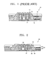
- FIG. 1 is a side cross-section of a spindle motor 10 in a conventional IBM micro-drive apparatus.
- the conventional spindle motor 10 includes a hub 11 , a magnet 13 , and yokes 15 .
- the hub 11 has ball bearings 17 in the space defined by the hub 11 and is rotatably supported by a base plate 19 .
- the magnet 13 is fastened to the hub 11 to provide a magnetic force.
- the yokes 15 are arranged around the outer boundary of the magnet 13 and wound with coils and generate turning forces to the spindle motor 10 by interaction between current flowing in the coils and the magnetic force of the magnet 13 .
- the yokes 15 are fixedly installed at the base plate 19 .
- the conventional IBM micro-drive apparatus of FIG. 1 is excellent in terms of capacity, unit cost per storage capacity, and future competitiveness but adopts a CF-II form which provides a thickness of 5.0 mm because of the difficulties of making slim.
- the conventional CF-II IBM micro-drive apparatus has the spindle motor 10 in which the magnet 13 and the yokes 15 are arranged to have the same central axis, thereby maximizing the rotation efficiency of the spindle motor 10 .
- such an arrangement is not suitable for the CF-I form having a great demand.
- there is not enough space in which to install stator yokes because of the thickness of an actuator installed in the space where the stator yokes are to be located.
- the present invention provides a slim spindle motor having an improved stator and a slim micro-drive apparatus using the slim spindle motor.
- a spindle motor including: a hub seating a disk thereon and rotatably mounted on a base plate by ball bearings; a ring-shaped magnet engaged to the outer boundary of the hub; and a stator formed by arranging a plurality of yokes in a round shape around the outer boundary of the ring-shaped magnet.
- the yokes include cores having ends curved to reduce the central axis offset between each of the yokes and the ring-shaped magnet and most of the yokes include coils that cover the cores.
- the curved ends are curved either upward or downward so as to be perpendicular to the central axis of the stator.
- a spindle motor including: a hub seating a disk thereon and rotatably mounted on a base plate by ball bearings; a ring-shaped magnet engaged to the outer boundary of the hub and having an increased diameter; and a stator formed by arranging a plurality of yokes in a round shape around the outer boundary of the ring-shaped magnet.
- the yokes include cores with increased diameters arranged such as to reduce the central axis offset between each of the yokes and the ring-shaped magnet and most of the yokes include coils that cover the cores.
- a spindle motor including: a hub seating a disk thereon and rotatably mounted on a base plate by ball bearings; a slim ring-shaped magnet engaged to the outer boundary of the hub; and a stator formed by arranging a plurality of slim yokes in a round shape around the outer boundary of the ring-shaped magnet.
- the slim yokes include cores arranged such as to reduce the central axis offset between each of the yokes and the ring-shaped magnet and most of the yokes include coils that cover the cores.
- a micro-drive apparatus including a base plate, a spindle motor, and an actuator.
- the spindle motor includes a hub seating a disk thereon and rotatably mounted on a base plate by ball bearings, a ring-shaped magnet engaged to the outer boundary of the hub, and a stator formed by arranging a plurality of yokes in a round shape around the outer boundary of the ring-shaped magnet.
- the yokes include cores having curved ends to reduce the central axis offset between the yokes and the ring-shaped magnet and most of the yokes include coils that cover the cores.
- the actuator includes a head, which moves over the disk to write/read data to/from the disk, and a suspension positioned at an end of the head.
- another micro-drive apparatus including a base plate, a spindle motor, and an actuator.
- the spindle motor includes a hub seating a disk thereon and rotatably mounted on a base plate by ball bearings, a ring-shaped magnet engaged to the outer boundary of the hub and having an increased diameter, and a stator formed by arranging a plurality of yokes in a round shape around the outer boundary of the ring-shaped magnet.
- the yokes include cores with increased diameters arranged such as to reduce the central axis offset between the yokes and the ring-shaped magnet and most of the yokes include coils that cover the cores.
- the actuator includes a head, which moves over the disk to write/read data to/from the disk, and a suspension positioned at an end of the head.
- the spindle motor includes a hub seating a disk thereon and rotatably mounted on a base plate by ball bearings, a slim ring-shaped magnet engaged to the outer boundary of the hub, and a stator formed by arranging a plurality of slim yokes in a round shape around the outer boundary of the ring-shaped magnet.
- the slim yokes include cores arranged such as to reduce the central axis offset between the yokes and the ring-shaped magnet and most of the yokes include coils that cover the cores.
- the actuator includes a head, which moves over the disk to write/read data to/from the disk, and a suspension positioned at an end of the head.
- the curved ends are curved either upward or downward so as to be perpendicular to the central axis of the stator.
- the magnet has a thickness of 1 mm or less.
- the cores have thicknesses of 0.5 mm or less.
- the number of cores is less than the number of poles of the magnet.
- the micro-drive apparatus further includes a damper installed on the hub to firmly clamp the disk to the hub and a screw locked in the hub to fix the clamper to the hub.
- FIG. 1 is a side cross-section of a spindle motor in a conventional IBM micro-drive apparatus
- FIG. 2 is a side cross-section of a slim spindle motor according to an embodiment of the present invention
- FIG. 3A is a cross-section of a first embodiment of a stator that can be installed in the slim spindle motor of FIG. 2 ;
- FIG. 3B is a perspective view of the stator of FIG. 3A ;
- FIG. 4 is a cross-section of a second embodiment of a stator that can be installed in the slim spindle motor of FIG. 2 ;
- FIG. 5 is a graph showing variations in the torque of a slim spindle motor according to an embodiment of the present invention with respect to the angle of the torque;
- FIG. 6 is a graph showing variations in an axial electromagnetic force with respect to its angle.
- FIG. 7 is an exploded perspective view of a disk drive apparatus in which the slim spindle motor of FIG. 2 is installed.
- a slim spindle motor 30 includes a hub 31 , a ring-shaped magnet 33 , and yokes 35 .
- the hub 31 is rotatably fixed to a base plate 39 by ball bearings 37 .
- the circular magnet 33 is fastened to the outer boundary of the hub 31 to provide a magnetic force.
- the yokes 35 are arranged in a round shape along the outer boundary of the magnet 33 .
- the magnet 33 functions as a rotor, and the yokes 35 function as a stator.
- the yokes 35 are wound with coils and generate electromagnetic forces that interact with the magnetic force of the magnet 33 so as to rotate the spindle motor 30 in a predetermined direction, which depends on the direction of current received from a flexible printed circuit (FPC, not shown).
- a screw 38 is locked in the central axis of the hub 31 to fix a damper (not shown), which seat a disk and fix the seated disk.
- the spindle motor 30 includes the circular magnet 33 smaller than the magnet 13 of the conventional spindle motor 10 of FIG. 1 and the yokes 35 installed along the outer boundary of the magnet 33 , thereby simply achieving slimming of a micro-drive apparatus.
- the yokes 35 are fixed onto the base plate 39 and rotate the spindle motor 30 by rotating the hub 31 to which the magnet 33 is fastened using an electromagnetic force.
- Making the central axes of the magnet 33 and each of the yokes 35 collinear can maximize a torque created by the electromagnetic force generated by interaction between the magnetic field of the magnet 33 and the electric field created by current flowing in coils 34 wound around the yokes 35 and can remove a force in an unnecessary Z-axis direction, that is, in the direction of the height of a drive apparatus.
- the spindle motor 30 of FIG. 2 includes a first embodiment of a stator whose central axes offset is removed, though the magnet 33 and the yoke 35 become slimmer.
- the magnet 33 having a high magnetic flux must be employed.
- first and second embodiments of a stator that can have the magnet 33 whose thickness is not slimmed are shown in FIGS. 3A and 4 .
- FIGS. 3A and 4 show first and second embodiments of a stator that can be installed in the slim spindle motor of FIG. 2 .
- FIG. 3B is a perspective view of the stator of FIG. 3A .
- yokes 35 a have ends 34 a curved upwardly such that the central axes of the yokes 35 a are collinear with that of a magnet 33 a and are arranged around the outer boundary of the magnet 33 a .
- the yokes 35 a are each comprised of a core 34 a and a coil 36 a which covers the core 34 a .
- the magnet 33 a is engaged to the hub 31 , and the yokes 35 a are fixed onto the base plate 39 .
- the yokes 35 a may have downwardly curved ends instead of the upwardly curved ends 34 a so as to make the central axis of each of the cores 34 a collinear with that of the magnet 33 a.
- the ring-shaped magnet 33 a is comprised of 12 poles, and 9 yokes 35 a are arranged in a round shape around the outer boundary of the magnet 33 a .
- a stator 32 is comprised of the yokes 35 a symmetrically arranged around the outer boundary of the magnet 33 a land an outer ring which supports the yokes 35 a .
- the yokes 35 a are each comprised of the core 34 a and the coil 36 a wound around the core 34 a.
- the hub 31 is installed at a high location and the diameter of the magnet 33 b is increased, thereby obtaining sufficient outer space.
- the yokes 35 b are positioned in the obtained space at a higher location than the location where the yokes 35 a in the first embodiment are positioned, such that the central axis of each of the yokes 35 b is made collinear with that of the magnet 33 b .
- the stator according to the second embodiment needs a space in which to install the yokes 35 b , the locations of other component elements must be adjusted.
- a spindle motor adopting the stator according to the first embodiment shown in FIGS. 3A and 3B is suitable for use in conventional CF-I disk drives.
- FIG. 5 is a graph showing variations in the torque of a slim spindle motor according to an embodiment of the present invention with respect to the angle of the torque.
- Reference numeral f 1 indicates an ideal case where an offset is 0, reference numeral f 2 indicates a case where an offset is 0.2 mm, reference numeral f 3 indicates a case where an offset has been removed by curving an end of a yoke upward by 0.2 mm, and reference numeral f 4 indicates a case where an offset is reduced from 0.12 mm to 0.08 mm by curving the end of the yoke upward by 0.2 mm.
- cases f 1 , f 3 , and f 4 have similar torque variations, while the torque of case f 2 is reduced from those of the other three cases.
- Such a reduction in torque denotes a reduction in the turning force of a spindle motor, and then if the turning force is reduced, the spindle motor operates unstably. Unstable operation of the spindle motor causes a disk seated on the spindle motor to rotate irregularly, making it difficult to accurately write data to an area on the disk and accurately read data.
- a spindle motor according to the present invention can have a stable torque characteristic by adopting a structure in which an offset between the central axes of a magnet and a yoke is reduced or removed.
- FIG. 6 is a graph showing variations in an axial electromagnetic force with respect to its angle.
- reference numeral g 1 indicates a force in a Z-axial direction, Fz, that represents 0 in an ideal case where an offset is zero.
- Reference numeral g 2 indicates Fz of about 0.2 N in the case f 2 of FIG. 4
- reference numeral g 4 indicates Fz of about 0.14 N in the case f 4 of FIG. 4 .
- a Z-axial offset generates the Z-axial force (Fz), and Fz increases as the Z-axial offset increases.
- Fz increases, the rotation of the spindle motor becomes unstable.
- FIG. 7 is an exploded perspective view of a disk drive apparatus 40 in which the slim spindle motor of FIG. 2 is installed.
- the disk drive apparatus 40 includes a disk 50 which stores information, a locking area 52 on which the disk 50 is seated, the spindle motor 30 which rotates the seated disk 50 , an actuator 43 having a head 47 capable of recording/reproducing data to/from the disk 50 , and a voice coil motor (not shown) comprised of a magnet assembly 46 and a voice coil 45 which drives the actuator 43 .
- the spindle motor 30 of FIG. 2 is positioned under the locking area 52 .
- a stator installed in the spindle motor 30 can be any of the stators shown in FIGS. 2 through 4 .
- an offset is removed by making the central axis of the magnet 33 , 33 a , or 33 b collinear with that of the yoke 35 , 35 a , or 35 b , respectively, so that a force in the Z-axial direction is removed.
- the actuator 43 receives an electrical signal from a printed circuit board (PCB; not shown) via a flexible printed circuit (FPC; not shown).
- PCB printed circuit board
- FPC flexible printed circuit
- the disk 50 is comprised of a parking zone minutely formed by laser at the inner area of the disk 50 and is fitted onto the spindle motor 30 so that the head 47 can be parked in the parking zone upon power-off.
- a data zone can be formed at the outside of the parking zone to record a magnetic signal on the data zone.
- the data zone has several tens of thousands of tracks on which a servo signal indicating locations where data is to be recorded has already been recorded along the circular shape of the disk 50 .
- the actuator 43 includes the voice coil motor (not shown) which drives the actuator 43 , a pivot bearing 48 around which the actuator 43 rotates, and the head 47 which has a write head to write data to the disk 50 and a read head to read data from the disk 50 .
- the actuator 43 is made very slim by attaching the voice coil 45 to a fantail molding portion, which is formed by extending a uni-mounting portion of a head gimbal assembly 41 .
- the PCB sends an electrical signal to the FPC, and the FPC transmits the received electrical signal to the actuator 43 .
- the electrical signal received by the actuator 43 is transmitted to the voice coil 45 .
- An electromagnetic force created by interaction between current flowing in the voice coil 45 and the magnetic force of the magnet assembly 46 rotates, the actuator 43 around the pivot bearing 48 to move the actuator 43 from the parking zone to the data zone.
- the present invention provides a stator whose central axes offsets between the magnet and yokes are reduced or removed, thereby obtaining a slim spindle motor and a slim micro-drive apparatus.
- stator in which the central axes of yokes are collinear with that of a magnet makes it possible to manufacture a slimmer and lighter spindle motor and a slimmer and lighter micro-drive apparatus that can maintain a stable driving performance and also be utilized as a mobile micro-drive apparatus.
Abstract
Description
Claims (10)
Priority Applications (1)
| Application Number | Priority Date | Filing Date | Title |
|---|---|---|---|
| US11/700,033 US20070127156A1 (en) | 2002-11-12 | 2007-01-31 | Slim spindle motor and micro-drive apparatus comprising the same |
Applications Claiming Priority (2)
| Application Number | Priority Date | Filing Date | Title |
|---|---|---|---|
| KR10-2002-0070063A KR100480788B1 (en) | 2002-11-12 | 2002-11-12 | Slim type spindle motor and micro drive apparatus comprising the same |
| KR2002-70063 | 2002-11-12 |
Related Child Applications (1)
| Application Number | Title | Priority Date | Filing Date |
|---|---|---|---|
| US11/700,033 Division US20070127156A1 (en) | 2002-11-12 | 2007-01-31 | Slim spindle motor and micro-drive apparatus comprising the same |
Publications (2)
| Publication Number | Publication Date |
|---|---|
| US20040090701A1 US20040090701A1 (en) | 2004-05-13 |
| US7190549B2 true US7190549B2 (en) | 2007-03-13 |
Family
ID=32226295
Family Applications (2)
| Application Number | Title | Priority Date | Filing Date |
|---|---|---|---|
| US10/444,960 Expired - Fee Related US7190549B2 (en) | 2002-11-12 | 2003-05-27 | Slim spindle motor and micro-drive apparatus comprising the same |
| US11/700,033 Abandoned US20070127156A1 (en) | 2002-11-12 | 2007-01-31 | Slim spindle motor and micro-drive apparatus comprising the same |
Family Applications After (1)
| Application Number | Title | Priority Date | Filing Date |
|---|---|---|---|
| US11/700,033 Abandoned US20070127156A1 (en) | 2002-11-12 | 2007-01-31 | Slim spindle motor and micro-drive apparatus comprising the same |
Country Status (3)
| Country | Link |
|---|---|
| US (2) | US7190549B2 (en) |
| JP (1) | JP2004166497A (en) |
| KR (1) | KR100480788B1 (en) |
Cited By (11)
| Publication number | Priority date | Publication date | Assignee | Title |
|---|---|---|---|---|
| US20060197395A1 (en) * | 2005-03-03 | 2006-09-07 | Takuro Iguchi | Spindle motor |
| US20060227455A1 (en) * | 2005-04-08 | 2006-10-12 | Nidec Corporation | Spindle motor with flexible circuit board and disk drive including the same |
| US20070127156A1 (en) * | 2002-11-12 | 2007-06-07 | Samsung Electronics Co., Ltd. | Slim spindle motor and micro-drive apparatus comprising the same |
| US20070170805A1 (en) * | 2006-01-25 | 2007-07-26 | Nidec Corporation | Armature, motor using the armature, and disk drive device using the motor |
| US20070210657A1 (en) * | 2006-03-07 | 2007-09-13 | Jian-Yeu Chen | Brushless DC motors and systems using the same |
| US20080129139A1 (en) * | 2004-12-08 | 2008-06-05 | Akihiko Wakitani | Spindle motor |
| US8259408B2 (en) | 2010-08-31 | 2012-09-04 | Nidec Corporation | Spindle motor having magnetic circuit for stator and rotor magnet, and storage disk drive having the same |
| US20130194907A1 (en) * | 2012-02-01 | 2013-08-01 | Alphana Technology Co., Ltd. | Rotating device |
| US8599517B1 (en) | 2012-11-19 | 2013-12-03 | Nidec Corporation | Spindle motor and disk drive apparatus |
| US8737017B1 (en) | 2012-11-19 | 2014-05-27 | Nidec Corporation | Spindle motor and disk drive apparatus |
| WO2016004078A1 (en) * | 2014-06-30 | 2016-01-07 | Nidec Motor Corporation | Large diameter fan having low profile radial air gap motor |
Families Citing this family (5)
| Publication number | Priority date | Publication date | Assignee | Title |
|---|---|---|---|---|
| JP2006077922A (en) * | 2004-09-10 | 2006-03-23 | Matsushita Electric Ind Co Ltd | Fluid bearing device and motor |
| JP4661211B2 (en) * | 2004-12-27 | 2011-03-30 | 日本電産株式会社 | Spindle motor |
| KR101320212B1 (en) * | 2012-08-17 | 2013-10-21 | 삼성전기주식회사 | Spindle motor and driving device of disc |
| EP4084291A4 (en) * | 2019-12-26 | 2024-01-10 | Amotech Co Ltd | Stator for electric motor, and electric motor comprising same |
| JP2023032622A (en) * | 2021-08-27 | 2023-03-09 | ミネベアミツミ株式会社 | Spindle motor and hard disk drive device |
Citations (21)
| Publication number | Priority date | Publication date | Assignee | Title |
|---|---|---|---|---|
| JPS5863067A (en) * | 1981-10-06 | 1983-04-14 | Pioneer Electronic Corp | Coreless motor |
| JPS5961460A (en) | 1982-09-30 | 1984-04-07 | Matsushita Electric Works Ltd | Brushless motor |
| JPS62214508A (en) * | 1986-03-14 | 1987-09-21 | Canon Electronics Inc | Cylinder unit |
| US4745312A (en) * | 1986-01-09 | 1988-05-17 | Kabushiki Kaisha Yaskawa Denki Seisakusho | Stepping motor |
| US4949000A (en) * | 1988-07-18 | 1990-08-14 | Mueller And Smith, Lpa | D.C. motor |
| JPH0538115A (en) | 1991-07-30 | 1993-02-12 | Nippon Densan Corp | Spindle motor |
| JPH06319246A (en) * | 1993-03-03 | 1994-11-15 | Synektron Corp | Thin motor for disk driving |
| KR960033073A (en) | 1995-02-13 | 1996-09-17 | 김광호 | How to clear by channel list |
| JPH1132466A (en) | 1997-07-10 | 1999-02-02 | Nippon Densan Corp | Motor |
| JPH1141891A (en) | 1997-07-11 | 1999-02-12 | Nippon Densan Corp | Stator for spindle motor and spindle motor provided with the same |
| JPH11275782A (en) | 1998-03-25 | 1999-10-08 | Nippon Densan Corp | Motor |
| JP2000041349A (en) * | 1998-07-17 | 2000-02-08 | Nippon Densan Corp | Thin type motor |
| JP2000083354A (en) * | 1998-09-03 | 2000-03-21 | Nippon Densan Corp | Manufacture of drive motor for recording disc |
| JP2000270504A (en) * | 1999-03-17 | 2000-09-29 | Nippon Densan Corp | Motor |
| US6344946B1 (en) * | 1997-04-01 | 2002-02-05 | Papst Licensing Gmbh | Disk storage device with improved spindle torque and acceleration |
| US20020074895A1 (en) * | 1999-12-14 | 2002-06-20 | Delphi Technologies, Inc. | Brushless motor with reduced rotor inertia |
| DE10064245A1 (en) * | 2000-12-22 | 2002-07-11 | Deutsch Zentr Luft & Raumfahrt | Stator for electrical machine has grooves accommodating coils, in which groove end is curved to match end curvature of coil. |
| JP2002233101A (en) | 2001-02-01 | 2002-08-16 | Sony Corp | Spindle motor and information record regenerator |
| US6437939B1 (en) * | 2000-01-19 | 2002-08-20 | International Business Machines Corporation | Ergonomic safety assist mechanism for handling micro-sized computer hard disk drives |
| US20020185929A1 (en) * | 2001-03-30 | 2002-12-12 | Gunhee Jang | Brushless DC motor with armature windings compensated by auxiliary windings |
| US6594111B1 (en) * | 2001-07-31 | 2003-07-15 | Western Digital Technologies, Inc. | Spindle motor having stator rim formed of curved arc segments |
Family Cites Families (6)
| Publication number | Priority date | Publication date | Assignee | Title |
|---|---|---|---|---|
| US4745132A (en) * | 1986-07-31 | 1988-05-17 | Betz Laboratories, Inc. | Biocidal compositions and use thereof employing a synergistic mixture of n-alkyldimethyl benzyl ammonium halide and n-dodecylguanidine |
| US5528436A (en) * | 1994-06-03 | 1996-06-18 | Hewlett-Packard Company | Low profile motor powered disk assembly for a recording/reproducing device |
| JPH0946938A (en) * | 1995-07-26 | 1997-02-14 | Toshiba Corp | Spindle motor, and its manufacture, and magnetic disc device equipped with spindle motor |
| KR100223629B1 (en) * | 1996-08-08 | 1999-10-15 | 윤종용 | Hard disk drive suspension using dynamic head loading method |
| WO2000062404A1 (en) * | 1999-04-07 | 2000-10-19 | International Business Machines Corporation | Spindle motor and disk device |
| KR100480788B1 (en) * | 2002-11-12 | 2005-04-07 | 삼성전자주식회사 | Slim type spindle motor and micro drive apparatus comprising the same |
-
2002
- 2002-11-12 KR KR10-2002-0070063A patent/KR100480788B1/en not_active IP Right Cessation
-
2003
- 2003-05-27 US US10/444,960 patent/US7190549B2/en not_active Expired - Fee Related
- 2003-11-12 JP JP2003382456A patent/JP2004166497A/en active Pending
-
2007
- 2007-01-31 US US11/700,033 patent/US20070127156A1/en not_active Abandoned
Patent Citations (21)
| Publication number | Priority date | Publication date | Assignee | Title |
|---|---|---|---|---|
| JPS5863067A (en) * | 1981-10-06 | 1983-04-14 | Pioneer Electronic Corp | Coreless motor |
| JPS5961460A (en) | 1982-09-30 | 1984-04-07 | Matsushita Electric Works Ltd | Brushless motor |
| US4745312A (en) * | 1986-01-09 | 1988-05-17 | Kabushiki Kaisha Yaskawa Denki Seisakusho | Stepping motor |
| JPS62214508A (en) * | 1986-03-14 | 1987-09-21 | Canon Electronics Inc | Cylinder unit |
| US4949000A (en) * | 1988-07-18 | 1990-08-14 | Mueller And Smith, Lpa | D.C. motor |
| JPH0538115A (en) | 1991-07-30 | 1993-02-12 | Nippon Densan Corp | Spindle motor |
| JPH06319246A (en) * | 1993-03-03 | 1994-11-15 | Synektron Corp | Thin motor for disk driving |
| KR960033073A (en) | 1995-02-13 | 1996-09-17 | 김광호 | How to clear by channel list |
| US6344946B1 (en) * | 1997-04-01 | 2002-02-05 | Papst Licensing Gmbh | Disk storage device with improved spindle torque and acceleration |
| JPH1132466A (en) | 1997-07-10 | 1999-02-02 | Nippon Densan Corp | Motor |
| JPH1141891A (en) | 1997-07-11 | 1999-02-12 | Nippon Densan Corp | Stator for spindle motor and spindle motor provided with the same |
| JPH11275782A (en) | 1998-03-25 | 1999-10-08 | Nippon Densan Corp | Motor |
| JP2000041349A (en) * | 1998-07-17 | 2000-02-08 | Nippon Densan Corp | Thin type motor |
| JP2000083354A (en) * | 1998-09-03 | 2000-03-21 | Nippon Densan Corp | Manufacture of drive motor for recording disc |
| JP2000270504A (en) * | 1999-03-17 | 2000-09-29 | Nippon Densan Corp | Motor |
| US20020074895A1 (en) * | 1999-12-14 | 2002-06-20 | Delphi Technologies, Inc. | Brushless motor with reduced rotor inertia |
| US6437939B1 (en) * | 2000-01-19 | 2002-08-20 | International Business Machines Corporation | Ergonomic safety assist mechanism for handling micro-sized computer hard disk drives |
| DE10064245A1 (en) * | 2000-12-22 | 2002-07-11 | Deutsch Zentr Luft & Raumfahrt | Stator for electrical machine has grooves accommodating coils, in which groove end is curved to match end curvature of coil. |
| JP2002233101A (en) | 2001-02-01 | 2002-08-16 | Sony Corp | Spindle motor and information record regenerator |
| US20020185929A1 (en) * | 2001-03-30 | 2002-12-12 | Gunhee Jang | Brushless DC motor with armature windings compensated by auxiliary windings |
| US6594111B1 (en) * | 2001-07-31 | 2003-07-15 | Western Digital Technologies, Inc. | Spindle motor having stator rim formed of curved arc segments |
Non-Patent Citations (3)
| Title |
|---|
| Dickert, "Development of High Bandwidth Torque Sensor for Control of High Performance Manipulators," Jan. 2, 1999, Thesis. Internet publication. * |
| English Translation of Korean Patent Office Action in corresponding application. |
| Hartmann, "Stator for electrical machine has grooves accommodating coils, in which groove end is curved to match end curvature of coil," Jul. 11, 2002, Derwent Information Ltd, Publication No. DE 10064245 A1, Derwent-ACC-No. 2002-584644, Abstract. * |
Cited By (15)
| Publication number | Priority date | Publication date | Assignee | Title |
|---|---|---|---|---|
| US20070127156A1 (en) * | 2002-11-12 | 2007-06-07 | Samsung Electronics Co., Ltd. | Slim spindle motor and micro-drive apparatus comprising the same |
| US7420309B2 (en) * | 2004-12-08 | 2008-09-02 | Matsushita Electric Industrial Co., Ltd. | Spindle motor |
| US20080129139A1 (en) * | 2004-12-08 | 2008-06-05 | Akihiko Wakitani | Spindle motor |
| US20060197395A1 (en) * | 2005-03-03 | 2006-09-07 | Takuro Iguchi | Spindle motor |
| US7443068B2 (en) * | 2005-03-03 | 2008-10-28 | Nidec Corporation | Spindle motor |
| US20060227455A1 (en) * | 2005-04-08 | 2006-10-12 | Nidec Corporation | Spindle motor with flexible circuit board and disk drive including the same |
| US20070170805A1 (en) * | 2006-01-25 | 2007-07-26 | Nidec Corporation | Armature, motor using the armature, and disk drive device using the motor |
| US7626305B2 (en) * | 2006-01-25 | 2009-12-01 | Nidec Corporation | Armature, motor using the armature, and disk drive device using the motor |
| US20070210657A1 (en) * | 2006-03-07 | 2007-09-13 | Jian-Yeu Chen | Brushless DC motors and systems using the same |
| US8259408B2 (en) | 2010-08-31 | 2012-09-04 | Nidec Corporation | Spindle motor having magnetic circuit for stator and rotor magnet, and storage disk drive having the same |
| US20130194907A1 (en) * | 2012-02-01 | 2013-08-01 | Alphana Technology Co., Ltd. | Rotating device |
| US8922944B2 (en) * | 2012-02-01 | 2014-12-30 | Samsung Electro-Mechanics Japan Advanced Technology Co., Ltd. | Rotating device |
| US8599517B1 (en) | 2012-11-19 | 2013-12-03 | Nidec Corporation | Spindle motor and disk drive apparatus |
| US8737017B1 (en) | 2012-11-19 | 2014-05-27 | Nidec Corporation | Spindle motor and disk drive apparatus |
| WO2016004078A1 (en) * | 2014-06-30 | 2016-01-07 | Nidec Motor Corporation | Large diameter fan having low profile radial air gap motor |
Also Published As
| Publication number | Publication date |
|---|---|
| KR100480788B1 (en) | 2005-04-07 |
| KR20040041953A (en) | 2004-05-20 |
| US20040090701A1 (en) | 2004-05-13 |
| US20070127156A1 (en) | 2007-06-07 |
| JP2004166497A (en) | 2004-06-10 |
Similar Documents
| Publication | Publication Date | Title |
|---|---|---|
| US20070127156A1 (en) | Slim spindle motor and micro-drive apparatus comprising the same | |
| US8416522B1 (en) | Disk drive with stepped motor hub | |
| EP0425312B1 (en) | Spindle motor assembly for a disk drive | |
| US6982513B2 (en) | Recording disk drive motor, recording disk drive employing the motor, a method of manufacturing a stator used in the recording disk drive motor, and core plate that is used in the manufacture of the stator | |
| EP3704695A2 (en) | Low-profile ball screw cam elevator mechanism for cold storage data storage device | |
| US11037590B2 (en) | In-pivot hybrid stepper motor for ball screw cam elevator mechanism for reduced-head hard disk drive | |
| US11410694B2 (en) | Axial flux permanent magnet motor for ball screw cam elevator mechanism for reduced-head hard disk drive | |
| EP0535018B1 (en) | Low noise spin motor for use in disk drive | |
| US20080012443A1 (en) | Motor and disk drive including the same | |
| US8476793B2 (en) | Stiffener tab for a spindle motor base plate | |
| US6921993B2 (en) | Geometrically aligning a stator and a base plate for a spindle motor | |
| US6744606B2 (en) | Dual plane actuator | |
| US6801388B2 (en) | Spindle motor and data recording/reproducing apparatus with dynamic-pressure fluid bearing supporting shaft and ball bearing support rotor | |
| US7486483B2 (en) | Rotating disk storage device with improved actuator arm | |
| US7904918B2 (en) | Disk device for recording and reading information | |
| KR100699887B1 (en) | Hard disk drive | |
| US7885041B2 (en) | Rotational disc type storage device | |
| JP4371117B2 (en) | Disk unit | |
| US8106560B2 (en) | Stiffness of brushless motor including stator core and disk drive | |
| US20070064341A1 (en) | Hard disk drive | |
| JP2002260350A (en) | Disk recording and reproducing apparatus | |
| JP2006127682A (en) | Disk unit | |
| JP2003051167A (en) | Magnetic disk device | |
| JP2004335107A (en) | Magnetic disk device |
Legal Events
| Date | Code | Title | Description |
|---|---|---|---|
| AS | Assignment |
Owner name: SAMSUNG ELECTRONICS CO., LTD., KOREA, REPUBLIC OF Free format text: ASSIGNMENT OF ASSIGNORS INTEREST;ASSIGNORS:BYUN, YONG-KYU;HONG, MIN-PYO;HAN, WOO-SUP;REEL/FRAME:014114/0818 Effective date: 20030519 |
|
| STCF | Information on status: patent grant |
Free format text: PATENTED CASE |
|
| FEPP | Fee payment procedure |
Free format text: PAYOR NUMBER ASSIGNED (ORIGINAL EVENT CODE: ASPN); ENTITY STATUS OF PATENT OWNER: LARGE ENTITY |
|
| FEPP | Fee payment procedure |
Free format text: PAYOR NUMBER ASSIGNED (ORIGINAL EVENT CODE: ASPN); ENTITY STATUS OF PATENT OWNER: LARGE ENTITY Free format text: PAYER NUMBER DE-ASSIGNED (ORIGINAL EVENT CODE: RMPN); ENTITY STATUS OF PATENT OWNER: LARGE ENTITY |
|
| FPAY | Fee payment |
Year of fee payment: 4 |
|
| AS | Assignment |
Owner name: SEAGATE TECHNOLOGY INTERNATIONAL, CAYMAN ISLANDS Free format text: ASSIGNMENT OF ASSIGNORS INTEREST;ASSIGNOR:SAMSUNG ELECTRONICS CO., LTD.;REEL/FRAME:028153/0689 Effective date: 20111219 |
|
| FPAY | Fee payment |
Year of fee payment: 8 |
|
| AS | Assignment |
Owner name: SAMSUNG ELECTRONICS CO., LTD., KOREA, REPUBLIC OF Free format text: CORRECTIVE ASSIGNMENT TO CORRECT THE REMOVE ERRONEOUSLY FILED NO. 7255478 FROM SCHEDULE PREVIOUSLY RECORDED AT REEL: 028153 FRAME: 0689. ASSIGNOR(S) HEREBY CONFIRMS THE ASSIGNMENT;ASSIGNOR:SAMSUNG ELECTRONICS CO., LTD.;REEL/FRAME:040001/0920 Effective date: 20160720 |
|
| FEPP | Fee payment procedure |
Free format text: MAINTENANCE FEE REMINDER MAILED (ORIGINAL EVENT CODE: REM.); ENTITY STATUS OF PATENT OWNER: LARGE ENTITY |
|
| LAPS | Lapse for failure to pay maintenance fees |
Free format text: PATENT EXPIRED FOR FAILURE TO PAY MAINTENANCE FEES (ORIGINAL EVENT CODE: EXP.); ENTITY STATUS OF PATENT OWNER: LARGE ENTITY |
|
| STCH | Information on status: patent discontinuation |
Free format text: PATENT EXPIRED DUE TO NONPAYMENT OF MAINTENANCE FEES UNDER 37 CFR 1.362 |
|
| FP | Lapsed due to failure to pay maintenance fee |
Effective date: 20190313 |